EP2420664A1 - Verfahren zur Steuerung eines Verbrennungsmotors - Google Patents
Verfahren zur Steuerung eines Verbrennungsmotors Download PDFInfo
- Publication number
- EP2420664A1 EP2420664A1 EP10173579A EP10173579A EP2420664A1 EP 2420664 A1 EP2420664 A1 EP 2420664A1 EP 10173579 A EP10173579 A EP 10173579A EP 10173579 A EP10173579 A EP 10173579A EP 2420664 A1 EP2420664 A1 EP 2420664A1
- Authority
- EP
- European Patent Office
- Prior art keywords
- fuel
- injector
- combustion
- engine
- flow curve
- Prior art date
- Legal status (The legal status is an assumption and is not a legal conclusion. Google has not performed a legal analysis and makes no representation as to the accuracy of the status listed.)
- Withdrawn
Links
- 238000002485 combustion reaction Methods 0.000 title claims abstract description 54
- 238000000034 method Methods 0.000 title claims abstract description 26
- 239000000446 fuel Substances 0.000 claims abstract description 149
- 238000001595 flow curve Methods 0.000 claims abstract description 36
- 238000002347 injection Methods 0.000 claims abstract description 33
- 239000007924 injection Substances 0.000 claims abstract description 33
- 238000012544 monitoring process Methods 0.000 claims abstract description 14
- 230000000593 degrading effect Effects 0.000 claims abstract description 8
- QVGXLLKOCUKJST-UHFFFAOYSA-N atomic oxygen Chemical compound [O] QVGXLLKOCUKJST-UHFFFAOYSA-N 0.000 claims description 16
- 239000001301 oxygen Substances 0.000 claims description 16
- 229910052760 oxygen Inorganic materials 0.000 claims description 16
- 238000012937 correction Methods 0.000 description 8
- 230000015556 catabolic process Effects 0.000 description 3
- 238000006731 degradation reaction Methods 0.000 description 3
- 238000013461 design Methods 0.000 description 3
- 230000006870 function Effects 0.000 description 3
- 239000007789 gas Substances 0.000 description 3
- 230000004044 response Effects 0.000 description 3
- 239000007921 spray Substances 0.000 description 3
- 238000007792 addition Methods 0.000 description 2
- 230000032683 aging Effects 0.000 description 2
- 238000013459 approach Methods 0.000 description 2
- 230000008901 benefit Effects 0.000 description 2
- 239000003344 environmental pollutant Substances 0.000 description 2
- 238000005259 measurement Methods 0.000 description 2
- 238000012986 modification Methods 0.000 description 2
- 230000004048 modification Effects 0.000 description 2
- 231100000719 pollutant Toxicity 0.000 description 2
- 101100276976 Drosophila melanogaster Drak gene Proteins 0.000 description 1
- 230000006399 behavior Effects 0.000 description 1
- 230000003197 catalytic effect Effects 0.000 description 1
- 230000008859 change Effects 0.000 description 1
- 238000011217 control strategy Methods 0.000 description 1
- 230000001419 dependent effect Effects 0.000 description 1
- 238000010586 diagram Methods 0.000 description 1
- 238000009434 installation Methods 0.000 description 1
- 230000007257 malfunction Effects 0.000 description 1
- 238000004519 manufacturing process Methods 0.000 description 1
- 230000002085 persistent effect Effects 0.000 description 1
- 230000011218 segmentation Effects 0.000 description 1
Images

Classifications
-
- F—MECHANICAL ENGINEERING; LIGHTING; HEATING; WEAPONS; BLASTING
- F02—COMBUSTION ENGINES; HOT-GAS OR COMBUSTION-PRODUCT ENGINE PLANTS
- F02D—CONTROLLING COMBUSTION ENGINES
- F02D41/00—Electrical control of supply of combustible mixture or its constituents
- F02D41/24—Electrical control of supply of combustible mixture or its constituents characterised by the use of digital means
- F02D41/2406—Electrical control of supply of combustible mixture or its constituents characterised by the use of digital means using essentially read only memories
- F02D41/2409—Addressing techniques specially adapted therefor
- F02D41/2412—One-parameter addressing technique
-
- F—MECHANICAL ENGINEERING; LIGHTING; HEATING; WEAPONS; BLASTING
- F02—COMBUSTION ENGINES; HOT-GAS OR COMBUSTION-PRODUCT ENGINE PLANTS
- F02D—CONTROLLING COMBUSTION ENGINES
- F02D41/00—Electrical control of supply of combustible mixture or its constituents
- F02D41/24—Electrical control of supply of combustible mixture or its constituents characterised by the use of digital means
- F02D41/2406—Electrical control of supply of combustible mixture or its constituents characterised by the use of digital means using essentially read only memories
- F02D41/2425—Particular ways of programming the data
- F02D41/2429—Methods of calibrating or learning
- F02D41/2438—Active learning methods
-
- F—MECHANICAL ENGINEERING; LIGHTING; HEATING; WEAPONS; BLASTING
- F02—COMBUSTION ENGINES; HOT-GAS OR COMBUSTION-PRODUCT ENGINE PLANTS
- F02D—CONTROLLING COMBUSTION ENGINES
- F02D41/00—Electrical control of supply of combustible mixture or its constituents
- F02D41/24—Electrical control of supply of combustible mixture or its constituents characterised by the use of digital means
- F02D41/2406—Electrical control of supply of combustible mixture or its constituents characterised by the use of digital means using essentially read only memories
- F02D41/2425—Particular ways of programming the data
- F02D41/2429—Methods of calibrating or learning
- F02D41/2441—Methods of calibrating or learning characterised by the learning conditions
-
- F—MECHANICAL ENGINEERING; LIGHTING; HEATING; WEAPONS; BLASTING
- F02—COMBUSTION ENGINES; HOT-GAS OR COMBUSTION-PRODUCT ENGINE PLANTS
- F02D—CONTROLLING COMBUSTION ENGINES
- F02D41/00—Electrical control of supply of combustible mixture or its constituents
- F02D41/24—Electrical control of supply of combustible mixture or its constituents characterised by the use of digital means
- F02D41/2406—Electrical control of supply of combustible mixture or its constituents characterised by the use of digital means using essentially read only memories
- F02D41/2425—Particular ways of programming the data
- F02D41/2429—Methods of calibrating or learning
- F02D41/2451—Methods of calibrating or learning characterised by what is learned or calibrated
- F02D41/2464—Characteristics of actuators
- F02D41/2467—Characteristics of actuators for injectors
-
- F—MECHANICAL ENGINEERING; LIGHTING; HEATING; WEAPONS; BLASTING
- F02—COMBUSTION ENGINES; HOT-GAS OR COMBUSTION-PRODUCT ENGINE PLANTS
- F02D—CONTROLLING COMBUSTION ENGINES
- F02D41/00—Electrical control of supply of combustible mixture or its constituents
- F02D41/20—Output circuits, e.g. for controlling currents in command coils
- F02D2041/202—Output circuits, e.g. for controlling currents in command coils characterised by the control of the circuit
- F02D2041/2055—Output circuits, e.g. for controlling currents in command coils characterised by the control of the circuit with means for determining actual opening or closing time
-
- F—MECHANICAL ENGINEERING; LIGHTING; HEATING; WEAPONS; BLASTING
- F02—COMBUSTION ENGINES; HOT-GAS OR COMBUSTION-PRODUCT ENGINE PLANTS
- F02D—CONTROLLING COMBUSTION ENGINES
- F02D2200/00—Input parameters for engine control
- F02D2200/02—Input parameters for engine control the parameters being related to the engine
- F02D2200/06—Fuel or fuel supply system parameters
- F02D2200/0614—Actual fuel mass or fuel injection amount
-
- F—MECHANICAL ENGINEERING; LIGHTING; HEATING; WEAPONS; BLASTING
- F02—COMBUSTION ENGINES; HOT-GAS OR COMBUSTION-PRODUCT ENGINE PLANTS
- F02D—CONTROLLING COMBUSTION ENGINES
- F02D2200/00—Input parameters for engine control
- F02D2200/02—Input parameters for engine control the parameters being related to the engine
- F02D2200/06—Fuel or fuel supply system parameters
- F02D2200/0614—Actual fuel mass or fuel injection amount
- F02D2200/0616—Actual fuel mass or fuel injection amount determined by estimation
-
- F—MECHANICAL ENGINEERING; LIGHTING; HEATING; WEAPONS; BLASTING
- F02—COMBUSTION ENGINES; HOT-GAS OR COMBUSTION-PRODUCT ENGINE PLANTS
- F02D—CONTROLLING COMBUSTION ENGINES
- F02D41/00—Electrical control of supply of combustible mixture or its constituents
- F02D41/30—Controlling fuel injection
- F02D41/38—Controlling fuel injection of the high pressure type
- F02D41/40—Controlling fuel injection of the high pressure type with means for controlling injection timing or duration
- F02D41/402—Multiple injections
Definitions
- the present invention generally relates to the control of internal combustion engines and more specifically to the control of fuel injection in IC engines for automotive vehicles.
- One requirement to reduce emissions from a spark ignited internal combustion engine is an accurate control of the combustion air/fuel ratio. This is usually done by metering a precisely controlled amount of fuel based on a measured or inferred air charge mass inducted into the engine; many control schemes are known in the art to control the air/fuel ratio. It is e.g. customary to install an oxygen sensor in the engine exhaust line pipe and to use the sensor output as a feedback signal for closed loop fuel control.
- the Engine Control Module is capable of determining the actual air/fuel ratio corresponding to each individual cylinder from the combined flow of exhaust gases; this function is known as ICFC (Individual Cylinder Fuel Control).
- ICFC Intelligent Cylinder Fuel Control
- the ECM develops a fuel command pulse width for each of the injectors that corresponds to the driver's requested torque.
- a lookup table is used that stores fuel amounts in function of e.g. engine speed, manifold air pressure, and other parameters.
- the ECM also uses a table storing closed-loop fuelling corrections, which is known as block learning memory (BLM).
- BBM block learning memory
- the BLM table entries are determined based on the oxygen sensor response, which when adequately filtered, provides a measure of the deviation of the average engine air/fuel ratio from stoichiometry (average here means for a bank, i.e. a set cylinders connected to the same exhaust manifold).
- the values from the base table and BLM are used to determine a global fuel amount.
- the ICFC module determines, also based on the oxygen sensor response, a cylinder specific fuel error that is used to develop individual cylinder correction factors applied to the global fuel amount. This final fuel amount is then converted into a pulse width command, which typically involves a lookup table storing fuel amounts vs. pulse widths.
- the present inventors have developed a non-intrusive method of assessing fuel errors that is particularly adapted for spray guided engines and allows learning actual fuelling data that may serve for subsequent corrective actions.
- the injection parameters are particularly critical in such engines that require precisely timed and measured injection pulses; otherwise the fuel does not burn, or only partially. And this is particularly critical with recent fuel injectors developed for spray guided/stratified charge engines that suffer from a sensible variability of flow performance.
- the present method may however be used with any GDI engine operable in homogeneous combustion.
- an injector learning event for an engine with a direct injection system, during which actual fuelling data related to a fuel injector are determined, wherein this injector learning event may only be enabled during an idle or deceleration condition of the engine.
- the injector learning event comprises the steps of:
- the degradation of combustion and split injection are performed at constant torque; operating at a constant operating point improves the reliability of the method and makes it transparent to the driver.
- These learned fuel data may then be stored, and used to take corrective actions regarding the pulse width command.
- the so-determined learned fuel data are used to update the flow curve table(s) that is/are stored in the Engine Control Unit and that store data indicative of fuel quantities (e.g. in mg) vs. injector pulse widths (i.e. injector opening time, e.g. in ms).
- the determined learned fuel data which hence typically correspond to learned fuel errors or amounts, are first stored and will subsequently be filtered to ensure that a general trend is observed in the learned values and/or that they are statistically relevant, before they are actually used for corrective actions on the pulse width commands, in particular for correcting the flow curve tables.
- the learned fuelling data may be the actually injected fuel amount or a deviation from the set value, referred to as fuel error.
- Any appropriate way of monitoring combustion allowing determining such values may be used; typically the combustion monitoring may be based on an oxygen sensor.
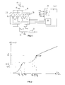
- reference sign 10 generally designates an automotive four-cylinder internal combustion engine.
- the engine receives intake air through an intake passage 12 that is variably restricted by a moveable throttle valve 14. Downstream of the throttle valve 14, intake air flows through an airflow meter 15 an enters an intake manifold 16 for distribution to the individual engine cylinders 18 in bank 20, via a plurality of intake runners.
- a fuel injector 22 is associated with each cylinder 18 and arranged for direct fuel injection so as to deliver a predetermined, metered quantity of fuel directly into the individual cylinders 18.
- the combustion products from each cylinder 18 are exhausted into the exhaust line 24 via a manifold continuing into an exhaust pipe 2 that comprises a catalytic converter 28 for emission control purposes.
- Reference sign 31 indicates an oxygen sensor providing an oxygen sensor signal to the ECU, the oxygen sensor signal being used for combustion performance monitoring, namely through the control of air/fuel ratio.
- the fuel control module of the ECU comprises a flow curve table 34 storing fuel amounts vs. pulse widths.
- the fuel amounts are determined in response to a number of inputs including: driver torque demand, manifold absolute pressure signal (MAP), intake air flow rate (MAF), engine speed (RPM) signal, and oxygen sensor signal.
- MAP manifold absolute pressure signal
- MAF intake air flow rate
- RPM engine speed
- oxygen sensor signal oxygen sensor signal
- the ECU determines an operational fuel amount required to reach the required and/or desired torque, typically depending on driver torque request, engine speed, manifold air pressure etc. This operational fuel amount, for each cylinder, is converted into a corresponding injector pulse width using the flow curve table 34. And the injectors 22 are operated by the fuel control module 30 to activate them for an on-time corresponding to the supplied injector pulse width command.
- the ECU may use various functionalities to control the performance of the combustion.
- the ECU may e.g. include a block learning memory BLM, which is a table that stores closed-loop fuelling corrections.
- BLM table entries are determined based on the oxygen sensor input, which when adequately filtered provides a measure of the deviation of the average (whole bank) engine air/fuel ratio from stoichiometry.
- the operational fuel amount can then be computed as the sum of a base fuel amount (determined from a base fuel table in function of torque demand, RPM, MAP and other signals) and the learned corrections from the BLM.
- a further possible ECU functionality for determining fuel errors is the ICFC scheme that is responsive to O 2 , MAP and RPM input signals and develops correction factors per cylinder so that the operational fuel amount may correspond to the sum of the base fuel scheduled plus the BLM correction, to which the ICFC correction factor is applied.
- an injector learning scheme is implemented in the ECU, which can be enabled during an idle condition or a deceleration condition of the engine.
- the learning scheme implies operating the engine into a homogeneous combustion mode (i.e. fuel injection takes place during the intake stroke) and concurrently degrading the combustion efficiency and/or splitting the injection pulses. While doing this, combustion performance (individual Imep via ICIE) & the exhaust individual airfuel (ICFC) are monitored to determine learned fuel data.
- These learned fuel data are representative of the actually injected fuel amount and may thus be expressed as fuel errors per cylinder, i.e. a deviation of a desired fuel amount from an actual fuel amount, or directly as the actually injected fuel amount.
- the learned fuel data can be used to take corrective actions on the fuel injection, in particular to correct injector pulse width commands.
- this learning scheme is to explore the actual flow performance (i.e. flow vs. pulse width) of the fuel injector at a time where it does not affect the car's driveability. This is done by varying the injection scheme and playing on the number of injection pulses within a cycle, the amount of injected fuel, and thus the spark timing. This is only possible in a homogeneous combustion mode, which is barely sensible to such actions.
- the degrading of the combustion and split mode are carried out as compared to the otherwise normal combustion control.
- the injected fuel quantity will not be as optimal as the conventionally determined operational fuel amount (as explained above) since the combustion will normally first be degraded (addition of fuel and retarded ignition) and the degradation will even increase.
- the engine When the engine is idling, it has the advantage of being at a stable operating point. There is no change of operating point and modifications of the injection scheme are not directly felt by the driver. In addition, the engine operation is not influenced by the powertrain. Also, the degradation of combustion and split injection performed during the learning mode are advantageously controlled to maintain a constant torque.
- Fig.2 shows a typical injector flow curve (the flow or fuel quantity delivered by the injector being plotted vs. pulse width).
- a flow curve is stored in the ECU for injector control, however it is discretized in the flow curve table 34, as it is known by those skilled in the art.
- This flow curve indicates the pulse width PW required to inject a fuel quantity Q F .
- the fuel quantity to be injected when running at idle is Q F I and requires according to the flow curve an injector on-time PW I .
- the exploration of the injector-specific flow performance is carried out as follows. Starting from the IDLE point (PW I , Q F I ), the combustion is first degraded, i.e. a greater fuel amount is injected and the spark timing is retarded; this is shown in Fig.3a) .
- the combustion is preferably progressively degraded, i.e. the fuel amount is e.g. successively increased by 20, 40 and 60%. Since combustion performance is permanently monitored during the learning scheme, a cylinder specific fuel error information is available which allows determining the actually injected fuel amount that corresponds to the pulse width command.
- Exploration of the flow curve below the IDLE point is then carried out by splitting the injection pulses, first into two pulses of same width to deliver a fuel amount equal to that of idle. Accordingly, the two pluses of Fig. 3b) have a width PW B (corresponding to 1 ⁇ 2 Q F
- the fuel injection is split into three pulses ( Fig.3c ) to deliver a fuel amount Q F
- Monitoring of the fuel combustion efficiency can be carried out by any appropriate method, and preferably based on oxygen sensing, e.g. using the oxygen sensor indicated 31 in Fig.1 .
- the fuel error of a given cylinder is determined based on three parameters available in the ECU:
- the determined fuel errors are then stored in a table vs. the corresponding pulse width, and can be used to correct fuel pulse commands.
- a table of correcting pulse width factors can e.g. be built.
- the pulse width command sent to the injection control module 30 may correspond to the sum of the pulse width looked-up from the flow curve table 34 and a correcting PW factor read from such table.
- the flow curve table 34 is updated based on the learned fuel data.
- the ECU stores one flow curve table per cylinder/injector.
- This fuel curve table is preferably specific to the fuel injector.
- injector specific fuel parameters can be installed at the moment of mounting the fuel injectors in the engine.
- it is known to store a characteristic equation (e.g. a polynomial) fitting a master flow curve representative of a population of injectors, and to install injector specific coefficients or terms at the time of mounting of the fuel injector.
- the ECU advantageously stores a set of characteristic equations for each injector, each characteristic equation within the set fitting a respective segment of such master flow curve representative of a general population of fuel injectors.
- the segmentation of the master flow curve means that the master flow curve is divided into distinct portions each described by a respective fitting equation over a distinct, non overlapping, pulse width range.
- injector specific parameters are loaded into the ECU and the flow curve tables are recalculated using the stored characteristic equations with the injector specific parameters.
- the equations may be polynomials and the injector specific parameters are coefficients for the polynomials.
Landscapes
- Engineering & Computer Science (AREA)
- Chemical & Material Sciences (AREA)
- Combustion & Propulsion (AREA)
- Mechanical Engineering (AREA)
- General Engineering & Computer Science (AREA)
- Combined Controls Of Internal Combustion Engines (AREA)
Priority Applications (1)
| Application Number | Priority Date | Filing Date | Title |
|---|---|---|---|
| EP10173579A EP2420664A1 (de) | 2010-08-20 | 2010-08-20 | Verfahren zur Steuerung eines Verbrennungsmotors |
Applications Claiming Priority (1)
| Application Number | Priority Date | Filing Date | Title |
|---|---|---|---|
| EP10173579A EP2420664A1 (de) | 2010-08-20 | 2010-08-20 | Verfahren zur Steuerung eines Verbrennungsmotors |
Publications (1)
| Publication Number | Publication Date |
|---|---|
| EP2420664A1 true EP2420664A1 (de) | 2012-02-22 |
Family
ID=43447743
Family Applications (1)
| Application Number | Title | Priority Date | Filing Date |
|---|---|---|---|
| EP10173579A Withdrawn EP2420664A1 (de) | 2010-08-20 | 2010-08-20 | Verfahren zur Steuerung eines Verbrennungsmotors |
Country Status (1)
| Country | Link |
|---|---|
| EP (1) | EP2420664A1 (de) |
Cited By (2)
| Publication number | Priority date | Publication date | Assignee | Title |
|---|---|---|---|---|
| GB2611759A (en) * | 2021-10-12 | 2023-04-19 | Delphi Tech Ip Ltd | Method of operating a fuel injection system |
| CN116255267A (zh) * | 2023-04-12 | 2023-06-13 | 东风汽车集团股份有限公司 | 一种喷油控制方法、控制装置、车辆、存储器及处理器 |
Citations (6)
| Publication number | Priority date | Publication date | Assignee | Title |
|---|---|---|---|---|
| DE19700711A1 (de) * | 1997-01-10 | 1998-09-17 | Siemens Ag | Verfahren zum Ausgleich des systematischen Fehlers an Einspritzvorrichtungen für eine Brennkraftmaschine |
| EP0947684A2 (de) * | 1998-03-31 | 1999-10-06 | Mazda Motor Corporation | Steuerungssystem für eine funkgezündete Brennkraftmaschine mit Direkt-Einspritzung |
| WO2001083972A1 (en) * | 2000-05-04 | 2001-11-08 | Bombardier Motor Corporation Of America | Method and system for fuel injector coefficient installation |
| US6382198B1 (en) | 2000-02-04 | 2002-05-07 | Delphi Technologies, Inc. | Individual cylinder air/fuel ratio control based on a single exhaust gas sensor |
| US20060107936A1 (en) * | 2003-07-16 | 2006-05-25 | Henri Mazet | Method of determining in real time the flow rate characteristic of a fuel injector |
| EP2108804A1 (de) * | 2008-04-08 | 2009-10-14 | Magneti Marelli Powertrain S.p.A. | Verfahren zur Bestimmung des tatsächlichen Versatzwerts einer Einspritzdüse eines Verbrennungsmotors |
-
2010
- 2010-08-20 EP EP10173579A patent/EP2420664A1/de not_active Withdrawn
Patent Citations (6)
| Publication number | Priority date | Publication date | Assignee | Title |
|---|---|---|---|---|
| DE19700711A1 (de) * | 1997-01-10 | 1998-09-17 | Siemens Ag | Verfahren zum Ausgleich des systematischen Fehlers an Einspritzvorrichtungen für eine Brennkraftmaschine |
| EP0947684A2 (de) * | 1998-03-31 | 1999-10-06 | Mazda Motor Corporation | Steuerungssystem für eine funkgezündete Brennkraftmaschine mit Direkt-Einspritzung |
| US6382198B1 (en) | 2000-02-04 | 2002-05-07 | Delphi Technologies, Inc. | Individual cylinder air/fuel ratio control based on a single exhaust gas sensor |
| WO2001083972A1 (en) * | 2000-05-04 | 2001-11-08 | Bombardier Motor Corporation Of America | Method and system for fuel injector coefficient installation |
| US20060107936A1 (en) * | 2003-07-16 | 2006-05-25 | Henri Mazet | Method of determining in real time the flow rate characteristic of a fuel injector |
| EP2108804A1 (de) * | 2008-04-08 | 2009-10-14 | Magneti Marelli Powertrain S.p.A. | Verfahren zur Bestimmung des tatsächlichen Versatzwerts einer Einspritzdüse eines Verbrennungsmotors |
Cited By (5)
| Publication number | Priority date | Publication date | Assignee | Title |
|---|---|---|---|---|
| GB2611759A (en) * | 2021-10-12 | 2023-04-19 | Delphi Tech Ip Ltd | Method of operating a fuel injection system |
| WO2023062041A1 (en) * | 2021-10-12 | 2023-04-20 | Delphi Technologies Ip Limited | Method of operating a fuel injection system |
| GB2611759B (en) * | 2021-10-12 | 2024-03-20 | Delphi Tech Ip Ltd | Method of operating a fuel injection system |
| US12338778B2 (en) | 2021-10-12 | 2025-06-24 | Phinia Delphi Luxembourg Sarl | Method of operating a fuel injection system |
| CN116255267A (zh) * | 2023-04-12 | 2023-06-13 | 东风汽车集团股份有限公司 | 一种喷油控制方法、控制装置、车辆、存储器及处理器 |
Similar Documents
| Publication | Publication Date | Title |
|---|---|---|
| US9650983B2 (en) | Method of controlling fuel injection in an internal combustion engine | |
| US7933710B2 (en) | Abnormality diagnosis device of internal combustion engine | |
| US6739310B2 (en) | Method and electronic control device for diagnosing the mixture production in an internal combustion engine | |
| CN104696086A (zh) | 诊断多喷射器系统中的喷射器变化性的方法 | |
| JPS6060019B2 (ja) | エンジンの制御方法 | |
| US11112333B2 (en) | Sensor failure diagnostic apparatus | |
| US20110125389A1 (en) | Method for the determination of the actual quantity of fuel injected in an internal combustion engine | |
| KR101443227B1 (ko) | 내연 기관의 연료 분사기에 대한 제어 파라미터를 결정하는 방법 및 장치 | |
| US7392789B2 (en) | Method for synchronizing cylinders in terms of quantities of fuel injected in an internal combustion engine | |
| JP2011252418A (ja) | 内燃機関の燃料噴射システム | |
| US20080121213A1 (en) | Engine control system including means for learning characteristics of individual fuel injectors | |
| US6947826B2 (en) | Method for compensating injection quality in each individual cylinder in internal combustion engines | |
| US7721707B2 (en) | Abnormality determination apparatus and abnormality determination method for valve | |
| US6805091B2 (en) | Method for determining the fuel content of the regeneration gas in an internal combustion engine comprising direct fuel-injection with shift operation | |
| GB2366004A (en) | A method for diagnosing cylinder bank dependant or cylinder bank independent faults in an internal combustion engine | |
| US7134429B2 (en) | Method and device for controlling an internal combustion engine | |
| US20240410325A1 (en) | Method of operating a fuel injection system | |
| JP4238043B2 (ja) | 内燃機関の燃料噴射制御装置 | |
| US8851052B2 (en) | Method and control device for operating an internal combustion engine | |
| JP5083228B2 (ja) | 燃料噴射制御装置 | |
| JP2018145817A (ja) | 内燃機関の異常診断装置 | |
| JP2009097453A (ja) | 内燃機関の制御装置 | |
| KR101262185B1 (ko) | 오토엔진들에서 밸브 양정 변경을 최적화하기 위한 방법 | |
| KR102703066B1 (ko) | 브레이크 부스터 유입 유량을 반영한 공연비 제어 방법 | |
| US6298839B1 (en) | Air-fuel ratio control apparatus and method for internal combustion engine |
Legal Events
| Date | Code | Title | Description |
|---|---|---|---|
| AK | Designated contracting states |
Kind code of ref document: A1 Designated state(s): AL AT BE BG CH CY CZ DE DK EE ES FI FR GB GR HR HU IE IS IT LI LT LU LV MC MK MT NL NO PL PT RO SE SI SK SM TR |
|
| AX | Request for extension of the european patent |
Extension state: BA ME RS |
|
| PUAI | Public reference made under article 153(3) epc to a published international application that has entered the european phase |
Free format text: ORIGINAL CODE: 0009012 |
|
| STAA | Information on the status of an ep patent application or granted ep patent |
Free format text: STATUS: THE APPLICATION IS DEEMED TO BE WITHDRAWN |
|
| 18D | Application deemed to be withdrawn |
Effective date: 20120823 |