EP2420672A2 - Windturbine - Google Patents
Windturbine Download PDFInfo
- Publication number
- EP2420672A2 EP2420672A2 EP11177566A EP11177566A EP2420672A2 EP 2420672 A2 EP2420672 A2 EP 2420672A2 EP 11177566 A EP11177566 A EP 11177566A EP 11177566 A EP11177566 A EP 11177566A EP 2420672 A2 EP2420672 A2 EP 2420672A2
- Authority
- EP
- European Patent Office
- Prior art keywords
- wind turbine
- rotor
- turbine according
- flow
- strömungsumlenkfläche
- Prior art date
- Legal status (The legal status is an assumption and is not a legal conclusion. Google has not performed a legal analysis and makes no representation as to the accuracy of the status listed.)
- Granted
Links
Images

Classifications
-
- F—MECHANICAL ENGINEERING; LIGHTING; HEATING; WEAPONS; BLASTING
- F03—MACHINES OR ENGINES FOR LIQUIDS; WIND, SPRING, OR WEIGHT MOTORS; PRODUCING MECHANICAL POWER OR A REACTIVE PROPULSIVE THRUST, NOT OTHERWISE PROVIDED FOR
- F03D—WIND MOTORS
- F03D3/00—Wind motors with rotation axis substantially perpendicular to the air flow entering the rotor
- F03D3/04—Wind motors with rotation axis substantially perpendicular to the air flow entering the rotor having stationary wind-guiding means, e.g. with shrouds or channels
- F03D3/0409—Wind motors with rotation axis substantially perpendicular to the air flow entering the rotor having stationary wind-guiding means, e.g. with shrouds or channels surrounding the rotor
-
- F—MECHANICAL ENGINEERING; LIGHTING; HEATING; WEAPONS; BLASTING
- F03—MACHINES OR ENGINES FOR LIQUIDS; WIND, SPRING, OR WEIGHT MOTORS; PRODUCING MECHANICAL POWER OR A REACTIVE PROPULSIVE THRUST, NOT OTHERWISE PROVIDED FOR
- F03D—WIND MOTORS
- F03D3/00—Wind motors with rotation axis substantially perpendicular to the air flow entering the rotor
- F03D3/005—Wind motors with rotation axis substantially perpendicular to the air flow entering the rotor the axis being vertical
-
- F—MECHANICAL ENGINEERING; LIGHTING; HEATING; WEAPONS; BLASTING
- F03—MACHINES OR ENGINES FOR LIQUIDS; WIND, SPRING, OR WEIGHT MOTORS; PRODUCING MECHANICAL POWER OR A REACTIVE PROPULSIVE THRUST, NOT OTHERWISE PROVIDED FOR
- F03D—WIND MOTORS
- F03D9/00—Adaptations of wind motors for special use; Combinations of wind motors with apparatus driven thereby; Wind motors specially adapted for installation in particular locations
- F03D9/20—Wind motors characterised by the driven apparatus
- F03D9/25—Wind motors characterised by the driven apparatus the apparatus being an electrical generator
-
- F—MECHANICAL ENGINEERING; LIGHTING; HEATING; WEAPONS; BLASTING
- F05—INDEXING SCHEMES RELATING TO ENGINES OR PUMPS IN VARIOUS SUBCLASSES OF CLASSES F01-F04
- F05B—INDEXING SCHEME RELATING TO WIND, SPRING, WEIGHT, INERTIA OR LIKE MOTORS, TO MACHINES OR ENGINES FOR LIQUIDS COVERED BY SUBCLASSES F03B, F03D AND F03G
- F05B2240/00—Components
- F05B2240/10—Stators
- F05B2240/13—Stators to collect or cause flow towards or away from turbines
-
- F—MECHANICAL ENGINEERING; LIGHTING; HEATING; WEAPONS; BLASTING
- F05—INDEXING SCHEMES RELATING TO ENGINES OR PUMPS IN VARIOUS SUBCLASSES OF CLASSES F01-F04
- F05B—INDEXING SCHEME RELATING TO WIND, SPRING, WEIGHT, INERTIA OR LIKE MOTORS, TO MACHINES OR ENGINES FOR LIQUIDS COVERED BY SUBCLASSES F03B, F03D AND F03G
- F05B2240/00—Components
- F05B2240/10—Stators
- F05B2240/13—Stators to collect or cause flow towards or away from turbines
- F05B2240/131—Stators to collect or cause flow towards or away from turbines by means of vertical structures, i.e. chimneys
-
- F—MECHANICAL ENGINEERING; LIGHTING; HEATING; WEAPONS; BLASTING
- F05—INDEXING SCHEMES RELATING TO ENGINES OR PUMPS IN VARIOUS SUBCLASSES OF CLASSES F01-F04
- F05B—INDEXING SCHEME RELATING TO WIND, SPRING, WEIGHT, INERTIA OR LIKE MOTORS, TO MACHINES OR ENGINES FOR LIQUIDS COVERED BY SUBCLASSES F03B, F03D AND F03G
- F05B2240/00—Components
- F05B2240/10—Stators
- F05B2240/13—Stators to collect or cause flow towards or away from turbines
- F05B2240/133—Stators to collect or cause flow towards or away from turbines with a convergent-divergent guiding structure, e.g. a Venturi conduit
-
- F—MECHANICAL ENGINEERING; LIGHTING; HEATING; WEAPONS; BLASTING
- F05—INDEXING SCHEMES RELATING TO ENGINES OR PUMPS IN VARIOUS SUBCLASSES OF CLASSES F01-F04
- F05B—INDEXING SCHEME RELATING TO WIND, SPRING, WEIGHT, INERTIA OR LIKE MOTORS, TO MACHINES OR ENGINES FOR LIQUIDS COVERED BY SUBCLASSES F03B, F03D AND F03G
- F05B2260/00—Function
- F05B2260/60—Fluid transfer
- F05B2260/601—Fluid transfer using an ejector or a jet pump
-
- Y—GENERAL TAGGING OF NEW TECHNOLOGICAL DEVELOPMENTS; GENERAL TAGGING OF CROSS-SECTIONAL TECHNOLOGIES SPANNING OVER SEVERAL SECTIONS OF THE IPC; TECHNICAL SUBJECTS COVERED BY FORMER USPC CROSS-REFERENCE ART COLLECTIONS [XRACs] AND DIGESTS
- Y02—TECHNOLOGIES OR APPLICATIONS FOR MITIGATION OR ADAPTATION AGAINST CLIMATE CHANGE
- Y02B—CLIMATE CHANGE MITIGATION TECHNOLOGIES RELATED TO BUILDINGS, e.g. HOUSING, HOUSE APPLIANCES OR RELATED END-USER APPLICATIONS
- Y02B10/00—Integration of renewable energy sources in buildings
- Y02B10/30—Wind power
-
- Y—GENERAL TAGGING OF NEW TECHNOLOGICAL DEVELOPMENTS; GENERAL TAGGING OF CROSS-SECTIONAL TECHNOLOGIES SPANNING OVER SEVERAL SECTIONS OF THE IPC; TECHNICAL SUBJECTS COVERED BY FORMER USPC CROSS-REFERENCE ART COLLECTIONS [XRACs] AND DIGESTS
- Y02—TECHNOLOGIES OR APPLICATIONS FOR MITIGATION OR ADAPTATION AGAINST CLIMATE CHANGE
- Y02E—REDUCTION OF GREENHOUSE GAS [GHG] EMISSIONS, RELATED TO ENERGY GENERATION, TRANSMISSION OR DISTRIBUTION
- Y02E10/00—Energy generation through renewable energy sources
- Y02E10/70—Wind energy
- Y02E10/74—Wind turbines with rotation axis perpendicular to the wind direction
Definitions
- the invention relates to a wind turbine, with a rotatable about a vertical axis under the action of an air flow rotor, the rotor on the outside surrounding air guide elements and coupled to a generator or coupled rotor shaft.
- Wind turbines are used to convert kinetic energy of an air stream into electrical energy by rotating blades through the kinetic energy, thereby driving a generator.
- Wind turbines with a vertical axis of rotation are suitable for power generation in places where turbulent air flows or strongly changing thermals occur.
- suitable installation sites are buildings with flat roofs in inner cities, steep slopes or mountain peaks.
- a wind turbine which has a rotor with a vertical rotor shaft having vertical drive blades.
- the drive blades are arranged so that a flow channel with decreasing cross-section is formed between two adjacent drive blades.
- the air flows through the rotor and leaves it on the side facing away from the wind.
- the rotor is surrounded by stationary vanes, which is intended to increase the wind catchment area.
- a wind turbine in which a rotor having blades is arranged in the interior of a stator having blades.
- the stator surrounds the rotor like a housing.
- the blades of the rotor and the stator are arranged so that the air flowing through the wind turbine is set in rotation and the wind turbine at the leaves the windward side.
- this wind turbine also has the disadvantage of creating a high back pressure in its interior.
- the invention is therefore based on the object of specifying a wind turbine, which can be flowed through by an air flow, without building up an undesirable high back pressure.
- the rotor surrounds a flow channel which has a flow deflection surface for deflecting the air flow to an outlet opening.
- the invention is based on the finding that the formation of the undesired dynamic pressure in the interior of the wind turbine can be prevented if the rotor surrounds a flow channel which has a flow deflection surface for deflecting the air flow to an outlet opening. Since the air flow is not stowed inside the wind turbine unlike conventional wind turbines, no undesirable high back pressure can arise.
- the flow deflection surface surrounds the rotor, that is to say it is arranged in the interior of the rotor.
- the Strömungsumsch design can be formed at least approximately conical in the wind turbine according to the invention. Due to the rotationally symmetrical conical configuration of the Strömungsumschuring materials is ensured that the air flow which flows horizontally sprialförmig through the air guide elements and the rotor is deflected after passing the rotor to the outlet opening.
- the preferably designed as a cone Strömungsumsch textures thereby causes the forced air flow direction change is continuous, so that no turbulence.
- the flow deflection surface has a hyperbolic shape.
- the means for generating negative pressure may include a Venturi nozzle into which the flow channel opens.
- a venturi is a flow channel that has a reduced diameter section which increases the velocity of the fluid flowing through it. If the flow channel of the wind turbine according to the invention opens in the region of the Venturi nozzle with a reduced diameter, a suction occurs due to the negative pressure in the Venturi nozzle, so that the air flow flowing through the wind turbine is sucked from the outlet opening. Since the flow channel in the interior of the wind turbine has a steady course, the flow remains laminar and thus low in resistance.
- the means for generating negative pressure in particular the venturi, is rotatably mounted and comprises a wind vane.
- the wind vane is designed so that it faces the wind, that is, under the influence of Windanströmung it turns so parallel to the wind that the resistance generated by them is minimal. In this state, the Venturi nozzle is flowed through in the longitudinal direction, so that the generated negative pressure is maximum.
- the flow channel may have a cross section which reduces at least in sections in the flow direction. Due to the decreasing cross-section is an at least low compression of the flowing air flow causes, which has an advantageous effect on the drive of the rotor and the generator.
- the flow deflection surface has a rounded foot region and the rotor and the flow deflection surface preferably merge into one another continuously.
- the continuous bends cause the desired laminar flow to be maintained inside the wind turbine.
- the flow diverting surface is shaped to deflect the airflow approximately 90 degrees upward from where it exits the wind turbine through the exhaust port.
- the air guide elements surrounding the rotor are formed as profiled guide vanes and the channels delimited by adjacent guide vanes have a cross-section which tapers in the direction of flow.
- the vanes are configured and arranged such that the airflow is guided along a helical path to the center of the rotor.
- the openings formed between adjacent air guide elements can be completely or partially closed.
- the openings can be selectively opened or closed, for example, by controllable lids, flaps or blinds.
- a control device can be provided, which can also be used to protect against strong wind gusts.
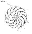
- a wind turbine 1 shown in a sectional view comprises a rotor 2 which is rotatable about a vertical axis.
- the rotor 2 comprises circumferentially spaced apart rotor blades 3, which are perpendicular in the rotor 2, wherein adjacent rotor blades 3 define flow channels 4, whose cross-section tapers in the flow direction.
- the rotor blades 3 are formed profiled.
- the rotor 2 is surrounded on the outside by air guide elements 5, which are formed as guide vanes.
- the number of rotor blades 3 corresponds to the number of air guide elements 5, but other embodiments are conceivable in which the number of rotor blades differs from the number of air guide elements. As in Fig. 1 is shown, go the rotor blades 3 and the air guide elements 5 at least approximately continuously into each other.
- the rotor 2 is closed at the top and at the bottom, the same applies to the stationary air guide elements 5, which form a ring which is closed on the top and bottom sides.
- a free space 6 which in the sectional view of Fig. 1 appears annular and in the center of a conical
- Flow deflection 7 is arranged.
- the Strömungsumsch materials may have a hyperbolic shape.
- An air stream flowing into the wind turbine 1 first flows through the air guide elements 5, then the flow channel 4 of the rotor 2 and passes through the free space 6 to a in Fig. 1 invisible outlet opening, from where the air flow leaves the wind turbine 1.
- the coupled to a generator for generating electrical energy rotor 2 is set in rotation. Since the air flow is deflected when flowing from a horizontal flow direction in a vertical flow direction, no excessive back pressure is built up inside the wind turbine 1, which would otherwise adversely affect the efficiency and the output power.
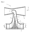
- Fig. 2 shows the wind turbine 1 in a sectional side view.
- the Strömungsumschting Structure 7 is at least approximately conical and has an upwardly pointing tip 8.
- a bottom 9 is provided, which rises in the flow direction, whereby the flow cross section is reduced and the air flow is at least slightly compressed.
- the rotor 2 which also has an inclined lower surface 10, adjoins the spoiler elements 5 continuously. In the flow direction adjoins the lower surface 10 of the rotor 2, an inclined rising foot portion 11 of the conical Strömungsumschuring the 7, wherein the lower surface 10 and the foot portion 11 merge into each other.
- the air flow is deflected by the flow deflection surface 7 from a horizontal flow direction by approximately 90 ° upwards in a vertical flow direction.
- a flow channel 12 is provided, whose cross-section tapers in the flow direction and which is flush with the inside of the rotor 2.
- the flow channel 12 has an outlet opening 13, which in the illustrated embodiment by approximately 90 ° is angled so that the air flow leaves the outlet opening 13 approximately horizontally.
- the outlet opening 13 of the flow channel 12 opens into a Venturi nozzle 14, which is flowed through in the direction of the arrow 15.
- the Venturi nozzle 14 has a conically tapering inlet region and a conically expanding outlet region, in the vicinity of the smallest diameter of the Venturi nozzle 14, the air flowing through is accelerated, so that a negative pressure is created which sucks the air flowing out of the outlet opening 13.
- the Venturi nozzle 14 supports the flow of air through the wind turbine 1.
- the negative pressure generated in the region of the outlet opening 13 is accelerated by the rotor 2 into the free space 6, whereby the air flow rate is increased.
- the venturi 14 is rotatably formed via a bearing, not shown, a wind vane causes the venturi always "turns" into the wind.
- the in the Fig. 1 to 4 The wind turbine shown is particularly suitable for installation on buildings, it can also be placed on mountain peaks or other places where strongly changing thermals or turbulent air currents are to be expected.
- a rotor shaft not shown in the drawings is connected to a generator to convert the kinetic energy of the rotor into electrical energy.
- the generator is coupled to an inverter to generate the AC voltage required for grid injection.
- the rotor 2 has at least one rotational speed sensor in order to monitor the rotational speed and to be able to decelerate when the maximum rotational speed is exceeded.
- a pressure sensor, a flow sensor, a vibration sensor or a temperature sensor may be present.
- the openings formed between adjacent air guide elements can be completely or partially closed.
- blinds can be provided on the outside of the air guide elements 5, alternatively, the openings can also be opened or closed by means of flaps or the like controlled by a control device.
- a heating device for example in the form of an electric heater, may be provided in the area of the stationary air guiding elements 5, whereby the transition between the air guiding elements 5 and the rotor 2 is protected against icing.
- the wind turbine 1 may have a steel construction as a substructure, in addition, at least one vibration damper may be provided in order to avoid the transmission of rotor frequencies to the ground, in particular to a building.
Landscapes
- Engineering & Computer Science (AREA)
- Life Sciences & Earth Sciences (AREA)
- Sustainable Development (AREA)
- Sustainable Energy (AREA)
- Chemical & Material Sciences (AREA)
- Combustion & Propulsion (AREA)
- Mechanical Engineering (AREA)
- General Engineering & Computer Science (AREA)
- Power Engineering (AREA)
- Wind Motors (AREA)
Abstract
Description
- Die Erfindung betrifft eine Windturbine, mit einem unter der Wirkung eines Luftstroms um eine vertikale Achse drehbaren Rotor, den Rotor außenseitig umgebenden Luftleitelementen und einer mit einem Generator koppelbaren oder gekoppelten Rotorwelle.
- Windkraftanlagen dienen zur Umwandlung von kinetischer Energie eines Luftstroms in elektrische Energie, indem Rotorblätter durch die kinetische Energie in Drehung versetzt werden, wodurch ein Generator angetrieben wird.
- Windturbinen mit vertikaler Drehachse eignen sich zur Stromerzeugung an Stellen, an denen turbulente Luftströmungen oder stark wechselnde Thermik auftritt. Beispiele für geeignete Aufstellorte sind Gebäude mit Flachdächern in Innenstädten, Steilabbruchkanten oder Berggipfel.
- In der
DE 10 2009 004 016 A1 wird eine Windturbine beschrieben, die einen Rotor mit vertikaler Rotorwelle aufweist, der senkrecht stehende Treibschaufeln besitzt. Die Treibschaufeln sind so angeordnet, dass zwischen zwei benachbarten Treibschaufeln ein Strömungskanal mit sich verringerndem Querschnitt gebildet ist. Die Luft durchströmt den Rotor und verlässt diesen an der dem Wind abgewandten Seite. Der Rotor ist von stationären Leitschaufeln umgeben, wodurch die Windauffangfläche vergrößert werden soll. - Derartige Windturbinen weisen allerdings den Nachteil auf, dass im Inneren ein hoher Staudruck entsteht, der die Leistung und den Wirkungsgrad der Windturbine beeinträchtigt.
- In der
DE 697 16 743 T2 wird eine Windturbine vorgeschlagen, bei der ein Schaufeln aufweisender Rotor im Inneren eines Schaufeln aufweisenden Stators angeordnet ist. Der Stator umgibt den Rotor dabei wie ein Gehäuse. Die Schaufeln des Rotors und des Stators sind so angeordnet, dass die durch die Windturbine strömende Luft in Rotation versetzt wird und die Windturbine an der dem Wind abgewandten Seite verlässt. Allerdings weist auch diese Windturbine den Nachteil der Entstehung eines hohen Staudrucks in ihrem Inneren auf. - Der Erfindung liegt daher die Aufgabe zugrunde, eine Windturbine anzugeben, die von einer Luftströmung durchströmt werden kann, ohne dass sich ein unerwünschter hoher Staudruck aufbaut.
- Zur Lösung dieser Aufgabe ist bei einer Windturbine der eingangs genannten Art erfindungsgemäß vorgesehen, dass der Rotor einen Strömungskanal umgibt, der eine Strömungsumlenkfläche zum Umlenken des Luftstroms zu einer Auslassöffnung aufweist.
- Der Erfindung liegt die Erkenntnis zugrunde, dass die Entstehung des unerwünschten Staudrucks im Inneren der Windturbine verhindert werden kann, sofern der Rotor einen Strömungskanal umgibt, der eine Strömungsumlenkfläche zum Umlenken des Luftstroms zu einer Auslassöffnung aufweist. Da der Luftstrom anders als bei herkömmlichen Windturbinen nicht im Inneren der Windturbine gestaut wird, kann kein unerwünscht hoher Staudruck entstehen. Die Strömungsumlenkfläche umgibt erfindungsgemäß den Rotor, das heißt sie ist im Inneren des Rotors angeordnet.
- Gemäß einer Weiterbildung der Erfindung kann die Strömungsumlenkfläche bei der erfindungsgemäßen Windturbine zumindest näherungsweise kegelförmig ausgebildet sein. Durch die rotationssymmetrische, kegelförmige Ausgestaltung der Strömungsumlenkfläche wird sicher gestellt, dass der Luftstrom, der horizontal sprialförmig durch die Luftleitelemente und den Rotor einströmt, nach dem Passieren des Rotors zu der Auslassöffnung umgelenkt wird. Die vorzugsweise als Kegel ausgebildete Strömungsumlenkfläche bewirkt dabei, dass die der Luftströmung aufgezwungene Richtungsänderung stetig ist, sodass keine Turbulenzen entstehen.
- Es wird besonders bevorzugt, dass die Strömungsumlenkfläche eine hyperbolische Form aufweist.
- Ein noch höherer Wirkungsgrad ergibt sich bei der erfindungsgemäßen Windturbine, wenn sie ein Mittel zum Erzeugen von Unterdruck im Bereich der Auslassöffnung aufweist. Durch das optional vorgesehene Unterdruckerzeugungsmittel wird ein Sog erzeugt, der sich über die Auslassöffnung entgegengesetzt zur Strömungsrichtung fortpflanzt und die Durchströmung fördert, ohne dass unzulässig hohe Strömungswiderstände entstehen.
- Bei der erfindungsgemäßen Windturbine kann das Mittel zum Erzeugen von Unterdruck eine Venturidüse umfassen, in die der Strömungskanal mündet. Eine Venturidüse ist ein Strömungskanal, der einen Abschnitt mit verringertem Durchmesser aufweist, wodurch sich die Geschwindigkeit des durchströmenden Mediums erhöht. Wenn der Strömungskanal der erfindungsgemäßen Windturbine in dem Bereich der Venturidüse mit verringertem Durchmesser mündet, entsteht durch den Unterdruck in der Venturidüse ein Sog, sodass der die Windturbine durchströmende Luftstrom von der Auslassöffnung her abgesaugt wird. Da der Strömungskanal im Inneren der Windturbine einen stetigen Verlauf aufweist, bleibt die Strömung laminar und damit widerstandsarm.
- Eine noch bessere Wirkung, auch bei beliebigen Windrichtungen, ergibt sich, wenn das Mittel zum Erzeugen von Unterdruck, insbesondere die Venturidüse, drehbar gelagert ist und eine Windfahne umfasst. Die Windfahne ist dazu so ausgebildet, dass sie sich in den Wind stellt, das heißt unter dem Einfluss der Windanströmung dreht sie sich so parallel zum Wind, dass der durch sie erzeugte Widerstand minimal ist. In diesem Zustand wird die Venturidüse in Längsrichtung durchströmt, sodass der erzeugte Unterdruck maximal ist.
- Bei der erfindungsgemäßen Windturbine kann es vorgesehen sein, dass der Strömungskanal einen sich zumindest abschnittsweise in Strömungsrichtung verringernden Querschnitt aufweist. Durch den sich verringernden Querschnitt wird eine zumindest geringe Kompression der durchströmenden Luftströmung bewirkt, die sich vorteilhaft auf den Antrieb des Rotors und des Generators auswirkt.
- Gemäß einer Weiterbildung der erfindungsgemäßen Windturbine kann es vorgesehen sein, dass die Strömungsumlenkfläche einen abgerundeten Fußbereich aufweist und der Rotor und die Strömungsumlenkfläche vorzugsweise stetig ineinander übergehen. Die stetigen Krümmungen bewirken, dass die gewünschte laminare Strömung im Inneren der Windturbine aufrechterhalten wird. Die Strömungsumlenkfläche ist so geformt, dass die Luftströmung näherungsweise um 90° nach oben abgelenkt wird, von wo aus sie die Windturbine durch die Auslassöffnung verlässt.
- Es liegt auch im Rahmen der Erfindung, dass die den Rotor umgebenden Luftleitelemente als profilierte Leitschaufeln ausgebildet sind und die von benachbarten Leitschaufeln begrenzten Kanäle einen sich in Strömungsrichtung verjüngenden Querschnitt aufweisen.
- Die Leitschaufeln sind so ausgebildet und angeordnet, dass die Luftströmung entlang einer spiralförmigen Bahn zum Zentrum des Rotors geführt wird.
- Um die einströmende Luftmenge zu steuern, kann es bei der erfindungsgemäßen Windturbine vorgesehen sein, dass die zwischen benachbarten Luftleitelementen gebildeten Öffnungen ganz oder teilweise verschließbar sind. Die Öffnungen können beispielsweise durch steuerbare Deckel, Klappen oder Jalousien selektiv geöffnet oder geschlossen werden. Dazu kann vorzugsweise eine Steuerungseinrichtung vorgesehen sein, die auch zur Absicherung gegenüber Starkwindböen eingesetzt werden kann.
- Weitere Vorteile und Einzelheiten der Erfindung werden anhand eines Ausführungsbeispiels unter Bezugnahme auf die Zeichnungen erläutert. Die Zeichnungen sind schematische Darstellungen und zeigen:
- Fig. 1
- eine entlang der Linie I-I von
Fig. 2 geschnittene Ansicht einer erfindungsgemäßen Windturbine; - Fig. 2
- eine geschnittene Seitenansicht der erfindungsgemäßen Windturbine von
Fig. 1 ; - Fig. 3
- eine Seitenansicht der Luftleitelemente der erfindungsgemäßen Windturbine; und
- Fig. 4
- eine perspektivische Ansicht der Luftleitelemente von
Fig. 3 . - Die in
Fig. 1 in einer geschnittenen Ansicht gezeigte Windturbine 1 umfasst einen Rotor 2, der um eine vertikale Achse drehbar ist. Der Rotor 2 umfasst in Umfangsrichtung voneinander beabstandet angeordnete Rotorschaufeln 3, die in dem Rotor 2 senkrecht stehen, wobei benachbarte Rotorschaufeln 3 Strömungskanäle 4 begrenzen, deren Querschnitt sich in Strömungsrichtung verjüngt. Die Rotorschaufeln 3 sind profiliert ausgebildet. - Der Rotor 2 ist außenseitig von Luftleitelementen 5 umgeben, die als Leitschaufeln ausgebildet sind. In dem dargestellten Ausführungsbeispiel entspricht die Anzahl der Rotorschaufeln 3 der Anzahl der Luftleitelemente 5, es sind jedoch auch andere Ausführungen denkbar, bei denen die Anzahl der Rotorschaufeln sich von der Anzahl der Luftleitelemente unterscheidet. Wie in
Fig. 1 gezeigt ist, gehen die Rotorschaufeln 3 und die Luftleitelemente 5 zumindest näherungsweise stetig ineinander über. - Der Rotor 2 ist an der Oberseite und an der Unterseite geschlossen, dasselbe gilt für die stationären Luftleitelemente 5, die einen Ring bilden, der oberseitig und unterseitig geschlossen ist.
- Im Inneren des Rotors 2 befindet sich ein Freiraum 6, der in der Schnittdarstellung von
Fig. 1 ringförmig erscheint und in dessen Zentrum eine kegelförmige - Strömungsumlenkfläche 7 angeordnet ist. Bei anderen Ausführungen kann die Strömungsumlenkfläche eine hyperbolische Form aufweisen.
- Ein in die Windturbine 1 einströmender Luftstrom durchströmt zunächst die Luftleitelemente 5, anschließend den Strömungskanal 4 des Rotors 2 und gelangt über den Freiraum 6 zu einer in
Fig. 1 nicht sichtbaren Auslassöffnung, von wo aus die Luftströmung in die Windturbine 1 verlässt. Beim Durchströmen der Windturbine 1 wird der mit einem Generator zur Erzeugung von elektrischer Energie gekoppelte Rotor 2 in Drehung versetzt. Da der Luftstrom beim Durchströmen von einer horizontalen Strömungsrichtung in eine vertikale Strömungsrichtung umgelenkt wird, wird im Inneren der Windturbine 1 kein übermäßiger Staudruck aufgebaut, der sich ansonsten nachteilig auf den Wirkungsgrad und die abgegebene Leistung auswirken würde. -
Fig. 2 zeigt die Windturbine 1 in einer geschnittenen Seitenansicht. InFig. 2 erkennt man, dass die Strömungsumlenkfläche 7 zumindest näherungsweise kegelförmig ausgebildet ist und eine nach oben weisende Spitze 8 aufweist. Ebenso ist ersichtlich, dass im Bereich der stationären Luftleitelemente 5 ein Boden 9 vorgesehen ist, der in Strömungsrichtung ansteigt, wodurch der Strömungsquerschnitt verringert und die Luftströmung zumindest geringfügig verdichtet wird. An die Luftleitelemente 5 schließt sich stetig der Rotor 2 an, der ebenfalls eine geneigte untere Fläche 10 aufweist. In Strömungsrichtung grenzt an die untere Fläche 10 des Rotors 2 ein geneigter ansteigender Fußbereich 11 der kegelförmigen Strömungsumlenkfläche 7 an, wobei die untere Fläche 10 und der Fußbereich 11 stetig ineinander übergehen. Beim Durchströmen der Windturbine 1 wird der Luftstrom durch die Strömungsumlenkfläche 7 von einer horizontalen Strömungsrichtung um näherungsweise 90° nach oben in eine vertikale Strömungsrichtung umgelenkt. - Oberhalb des Rotors 2 ist ein Strömungskanal 12 vorgesehen, dessen Querschnitt sich in Strömungsrichtung verjüngt und der flächenbündig mit der Innenseite des Rotors 2 abschließt. In seinem oberen Bereich weist der Strömungskanal 12 eine Auslassöffnung 13 auf, die in dem dargestellten Ausführungsbeispiel um ca. 90° abgewinkelt ist, sodass die Luftströmung die Auslassöffnung 13 näherungsweise waagerecht verlässt. Die Auslassöffnung 13 des Strömungskanals 12 mündet in eine Venturidüse 14, die in Richtung des Pfeils 15 durchströmt wird. Die Venturidüse 14 weist einen sich konisch verjüngenden Einlassbereich und einen sich konisch erweiternden Auslassbereich auf, in der Nähe des kleinsten Durchmessers der Venturidüse 14 wird die durchströmende Luft beschleunigt, sodass ein Unterdruck entsteht, der die aus der Auslassöffnung 13 ausströmende Luft ansaugt. Somit unterstützt die Venturidüse 14 das Durchströmen der Luftströmung durch die Windturbine 1. Durch den im Bereich der Auslassöffnung 13 erzeugten Unterdruck wird vom Rotor 2 in den Freiraum 6 geförderte Luft beschleunigt, wodurch der Luftdurchsatz erhöht wird. Die Venturidüse 14 ist über eine nicht dargestellte Lagerung drehbar ausgebildet, eine Windfahne bewirkt, dass die Venturidüse sich immer "in den Wind" dreht.
- In der Seitenansicht von
Fig. 3 und der perspektivischen Ansicht vonFig. 4 sind die Luftleitelemente 5 sowie der in Strömungsrichtung ansteigende Boden 9 gezeigt. Durch die Position der Luftleitelemente 5 ist gewährleistet, dass unabhängig von der Anströmrichtung und somit unabhängig von der aktuellen Windrichtung stets Luft in die Windturbine 1 einströmt, die entlang eines spiralförmigen Strömungswegs durch den Rotor 2 strömt, diesen dabei in Drehung versetzt und im Bereich der zentralen kegelförmigen Strömungsumlenkfläche 7 vertikal nach oben abgelenkt wird und die Windturbine 1 über die Auslassöffnung 13 verlässt. - Die in den
Fig. 1 bis 4 gezeigte Windturbine eignet sich besonders für die Aufstellung auf Gebäuden, daneben kann sie auch auf Berggipfeln oder an anderen Orten platziert werden, wo stark wechselnde Thermik oder turbulente Luftströmungen zu erwarten sind. - Eine in den Zeichnungen nicht dargestellte Rotorwelle ist mit einem Generator verbunden, um die Bewegungsenergie des Rotors in elektrische Energie umzuwandeln. Der Generator ist mit einem Wechselrichter gekoppelt, um die zur Netzeinspeisung erforderliche Wechselspannung zu erzeugen.
- Aus Sicherheitsgründen weist der Rotor 2 wenigstens einen Drehzahlsensor auf, um die Drehzahl zu überwachen und bei einer Überschreitung der höchstzulässigen Drehzahl einen Abbremsvorgang vornehmen zu können. Daneben kann ein Drucksensor, ein Strömungssensor, ein Vibrationssensor oder ein Temperatursensor vorhanden sein.
- Um eine Überlastung bei sehr hohen Windgeschwindigkeiten zu vermeiden, können die zwischen benachbarten Luftleitelementen gebildeten Öffnungen ganz oder teilweise verschlossen werden. Dazu können Jalousien an der Außenseite der Luftleitelemente 5 vorgesehen sein, alternativ können die Öffnungen auch mittels Klappen oder dergleichen durch eine Steuerungseinrichtung gesteuert geöffnet oder geschlossen werden. Um eine Vereisung zu vermeiden, kann eine Heizeinrichtung, beispielsweise in Form einer Elektroheizung, im Bereich der stationären Luftleitelemente 5 vorgesehen sein, wodurch der Übergang zwischen den Luftleitelementen 5 und dem Rotor 2 vor Vereisung geschützt wird. Die Windturbine 1 kann eine Stahlkonstruktion als Unterbau aufweisen, zusätzlich kann wenigstens ein Vibrationsdämpfer vorgesehen sein, um die Übertragung von Rotorfrequenzen auf den Untergrund, insbesondere auf ein Gebäude, zu vermeiden.
Claims (11)
- Windturbine (1), mit einem unter der Wirkung eines Luftstroms um eine vertikale Achse drehbaren Rotor (2), den Rotor (2) außenseitig umgebenden Luftleitelementen (5) und einer mit einem Generator koppelbaren oder gekoppelten Rotorwelle, dadurch gekennzeichnet, dass der Rotor (2) einen Strömungskanal (4) umgibt, der eine Strömungsumlenkfläche (7) zum Umlenken des Luftstroms zu einer Auslassöffnung (13) aufweist.
- Windturbine nach Anspruch 1, dadurch gekennzeichnet, dass die Strömungsumlenkfläche (7) zumindest näherungsweise kegelförmig ausgebildet ist.
- Windturbine nach Anspruch 1 oder 2, dadurch gekennzeichnet, dass sie ein Mittel zum Erzeugen von Unterdruck im Bereich der Auslassöffnung (13) aufweist.
- Windturbine nach Anspruch 3, dadurch gekennzeichnet, dass das Mittel zum Erzeugen von Unterdruck eine Venturidüse (14) umfasst, in die der Strömungskanal mündet.
- Windturbine nach Anspruch 4, dadurch gekennzeichnet, dass das Mittel zum Erzeugen von Unterdruck, insbesondere die Venturidüse (14), drehbar gelagert ist und vorzugsweise eine Windfahne umfasst.
- Windturbine nach einem der vorangehenden Ansprüche, dadurch gekennzeichnet, dass der Strömungskanal einen sich zumindest abschnittsweise in Strömungsrichtung verringernden Querschnitt aufweist.
- Windturbine nach einem der vorangehenden Ansprüche, dadurch gekennzeichnet, dass die Strömungsumlenkfläche (7) einen abgerundeten Fußbereich (11) aufweist und der Rotor (2) und die Strömungsumlenkfläche (7) vorzugsweise stetig ineinander übergehen.
- Windturbine nach einem der vorangehenden Ansprüche, dadurch gekennzeichnet, dass die den Rotor (2) umgebenden Luftleitelemente (5) als profilierte Leitschaufeln ausgebildet sind und die von benachbarten Leitschaufeln begrenzten Kanäle einen sich in Strömungsrichtung verjüngenden Querschnitt aufweisen.
- Windturbine nach einem der vorangehenden Ansprüche, dadurch gekennzeichnet, dass die zwischen benachbarten Luftleitelementen (5) gebildeten Öffnungen ganz oder teilweise verschließbar sind.
- Windturbine nach einem der vorangehenden Ansprüche, dadurch gekennzeichnet, dass eine Steuerungseinrichtung zum Öffnen und Schließen der Öffnungen vorgesehen ist.
- Windturbine nach einem der vorangehenden Ansprüche, dadurch gekennzeichnet, dass die Strömungsumlenkfläche zumindest näherungsweise hyperbolisch ausgebildet ist.
Applications Claiming Priority (2)
| Application Number | Priority Date | Filing Date | Title |
|---|---|---|---|
| DE202010011596 | 2010-08-17 | ||
| DE102010048815.1A DE102010048815B4 (de) | 2010-08-17 | 2010-10-20 | Windturbine |
Publications (3)
| Publication Number | Publication Date |
|---|---|
| EP2420672A2 true EP2420672A2 (de) | 2012-02-22 |
| EP2420672A3 EP2420672A3 (de) | 2014-05-28 |
| EP2420672B1 EP2420672B1 (de) | 2017-01-25 |
Family
ID=44532664
Family Applications (1)
| Application Number | Title | Priority Date | Filing Date |
|---|---|---|---|
| EP11177566.4A Active EP2420672B1 (de) | 2010-08-17 | 2011-08-15 | Windturbine |
Country Status (3)
| Country | Link |
|---|---|
| EP (1) | EP2420672B1 (de) |
| DE (1) | DE102010048815B4 (de) |
| ES (1) | ES2622436T3 (de) |
Cited By (2)
| Publication number | Priority date | Publication date | Assignee | Title |
|---|---|---|---|---|
| CN107269469A (zh) * | 2017-08-11 | 2017-10-20 | 周东宁 | 低压引流式风力发电机 |
| CN117267046A (zh) * | 2023-10-13 | 2023-12-22 | 厦门晶欣电子股份有限公司 | 一种新型发电机 |
Families Citing this family (2)
| Publication number | Priority date | Publication date | Assignee | Title |
|---|---|---|---|---|
| DE202017004836U1 (de) | 2017-09-16 | 2018-11-05 | Alfred M.H. Lienkamp | VEK-Windturbine aus vertikal-ellipsoiden-konvex-Flügeln mit horizontal und vertikal winkelverstellbarer Vorrichtung bei gleichzeitig windströmungsabhängig manuell und programmiert steuerbaren Teleskop-Armen |
| DE102023120931A1 (de) * | 2023-08-07 | 2025-02-13 | Jakob Schumacher | Wind- oder Wasserkraftanlage mit zwei ineinandergreifenden, gegenläufigen Rotoren |
Citations (2)
| Publication number | Priority date | Publication date | Assignee | Title |
|---|---|---|---|---|
| DE69716743T2 (de) | 1996-08-23 | 2003-06-12 | Georges Gual | Windturbine mit senkrechter drehachse und niedriger bauhöhe |
| DE102009004016A1 (de) | 2008-02-25 | 2009-12-10 | Reinhard Fuchs | Windkraftanlage |
Family Cites Families (12)
| Publication number | Priority date | Publication date | Assignee | Title |
|---|---|---|---|---|
| US4018543A (en) * | 1975-09-19 | 1977-04-19 | The Raymond Lee Organization, Inc. | Whirlwind power system |
| US4433544A (en) * | 1982-05-19 | 1984-02-28 | The United States Of America As Represented By The Administrator Of The National Aeronautics And Space Administration | Wind and solar powered turbine |
| DE3301885A1 (de) * | 1983-01-21 | 1984-07-26 | Heinrich 4350 Recklinghausen Quante | Windgenerator |
| FI894745L (fi) * | 1989-10-06 | 1991-04-07 | Ahti Kalervo Heikkinen | Vindkraftverk. |
| US5300817A (en) * | 1993-04-16 | 1994-04-05 | Baird William R | Solar venturi turbine |
| US6626636B2 (en) * | 2001-08-06 | 2003-09-30 | Awa Research, Llc | Column airflow power apparatus |
| US6655907B2 (en) * | 2002-03-18 | 2003-12-02 | Future Energy Solutions Inc | Fluid driven vacuum enhanced generator |
| RU2251022C1 (ru) * | 2003-11-13 | 2005-04-27 | Зазимко Вадим Николаевич | Ветроэнергетическая установка |
| FR2874240B1 (fr) * | 2004-08-11 | 2006-11-24 | Michel Alain Coustou | Tour aerogeneratrice (combinant effet cheminee, effet de serre, force de coriolis et effet venturi) |
| ITBO20050745A1 (it) * | 2005-12-06 | 2007-06-07 | Conte Carlo | Macchina per la generazione d'energia eletrtica da fonti rinnovabili complementari |
| FR2913071A1 (fr) * | 2007-02-22 | 2008-08-29 | Pierre Lecanu | Eolienne d'axe vertical |
| RU2369772C2 (ru) * | 2007-07-12 | 2009-10-10 | Владимир Владимирович Тебуев | Выработка электроэнергии с размещением ветрогенератора в вертикальном вытяжном воздушном канале в конструкции жилого здания |
-
2010
- 2010-10-20 DE DE102010048815.1A patent/DE102010048815B4/de not_active Expired - Fee Related
-
2011
- 2011-08-15 ES ES11177566.4T patent/ES2622436T3/es active Active
- 2011-08-15 EP EP11177566.4A patent/EP2420672B1/de active Active
Patent Citations (2)
| Publication number | Priority date | Publication date | Assignee | Title |
|---|---|---|---|---|
| DE69716743T2 (de) | 1996-08-23 | 2003-06-12 | Georges Gual | Windturbine mit senkrechter drehachse und niedriger bauhöhe |
| DE102009004016A1 (de) | 2008-02-25 | 2009-12-10 | Reinhard Fuchs | Windkraftanlage |
Cited By (2)
| Publication number | Priority date | Publication date | Assignee | Title |
|---|---|---|---|---|
| CN107269469A (zh) * | 2017-08-11 | 2017-10-20 | 周东宁 | 低压引流式风力发电机 |
| CN117267046A (zh) * | 2023-10-13 | 2023-12-22 | 厦门晶欣电子股份有限公司 | 一种新型发电机 |
Also Published As
| Publication number | Publication date |
|---|---|
| DE102010048815B4 (de) | 2014-07-17 |
| EP2420672B1 (de) | 2017-01-25 |
| DE102010048815A1 (de) | 2012-02-23 |
| EP2420672A3 (de) | 2014-05-28 |
| ES2622436T3 (es) | 2017-07-06 |
Similar Documents
| Publication | Publication Date | Title |
|---|---|---|
| EP1859164B1 (de) | Verfahren und vorrichtung zur nutzung der windenergie | |
| DE102011014476B4 (de) | Windturbine | |
| HUT66089A (en) | Process and installation for producing useable energy from parallel flows | |
| EP2420672B1 (de) | Windturbine | |
| WO2013041632A2 (de) | Windkraftkonverter | |
| DE102012010576B4 (de) | Windkraftmaschine mit Drehachse im Wesentlichen rechtwinklig zur Windrichtung | |
| DE102013101725A1 (de) | Kombinierte Windanlage "AeroGreen" | |
| DE112017004377B4 (de) | Windturbinenanlage | |
| EP2236816A2 (de) | Kleinwindkraftanlage | |
| EP2699797B1 (de) | Windkraftanlage | |
| EP2636892A2 (de) | Windkraftanlage und Verfahren zum Erzeugen von rotatorischer Energie durch Wind | |
| CH714302B1 (de) | Aerodynamisch optimiertes Rotorblatt. | |
| DE102007062483A1 (de) | Strömungskraftanlage mit einem mehrere Flügel tragenden Rotor, der etwa radial zur Rotorachse angeströmt wird, und mit einer Mehrzahl von feststehenden Strömungsleitblechen, sowie Verfahren zum Betrieb dieser Strömungskraftanlage | |
| DE29907940U1 (de) | Windkraftanlage mit Vertikalrotor | |
| DE102010035178B4 (de) | Windkraftanlage | |
| EP2728174A1 (de) | Windkraftanlage zur Energiegewinnung | |
| DE102008058030A1 (de) | Windkraftanlage für ein Dach | |
| DE10157821A1 (de) | Windkraftanlage | |
| DE102024121235A1 (de) | Wind- oder Wasserkraftanlage | |
| DE202024104364U1 (de) | Wind- oder Wasserkraftanlage | |
| DE102013004277A1 (de) | Druckerzeugungseinrichtung für eine Anlage zur Erzeugung von Energie aus Solar- und/oder Windenergie | |
| EP2971759B1 (de) | Druckerzeugungseinrichtung zur erzeugung von energie aus solar- und/oder windenergie | |
| DE102008019276A1 (de) | Vorrichtung zum Konzentrieren der Strömungsenergie eines auf einen Rotor wirkenden Gas- oder Flüssigkeitsstroms, Windkraftanlage sowie Verfahren zum Betreiben einer Windkraftanlage | |
| CH704383A2 (de) | Windkraftvorrichtung. | |
| WO2017144038A1 (de) | Windturbine und verfahren zur erzeugung von elektrischer energie |
Legal Events
| Date | Code | Title | Description |
|---|---|---|---|
| AK | Designated contracting states |
Kind code of ref document: A2 Designated state(s): AL AT BE BG CH CY CZ DE DK EE ES FI FR GB GR HR HU IE IS IT LI LT LU LV MC MK MT NL NO PL PT RO RS SE SI SK SM TR |
|
| AX | Request for extension of the european patent |
Extension state: BA ME |
|
| PUAI | Public reference made under article 153(3) epc to a published international application that has entered the european phase |
Free format text: ORIGINAL CODE: 0009012 |
|
| PUAL | Search report despatched |
Free format text: ORIGINAL CODE: 0009013 |
|
| AK | Designated contracting states |
Kind code of ref document: A3 Designated state(s): AL AT BE BG CH CY CZ DE DK EE ES FI FR GB GR HR HU IE IS IT LI LT LU LV MC MK MT NL NO PL PT RO RS SE SI SK SM TR |
|
| AX | Request for extension of the european patent |
Extension state: BA ME |
|
| RIC1 | Information provided on ipc code assigned before grant |
Ipc: F03D 3/00 20060101ALI20140422BHEP Ipc: F03D 3/04 20060101AFI20140422BHEP |
|
| 17P | Request for examination filed |
Effective date: 20141009 |
|
| RBV | Designated contracting states (corrected) |
Designated state(s): AL AT BE BG CH CY CZ DE DK EE ES FI FR GB GR HR HU IE IS IT LI LT LU LV MC MK MT NL NO PL PT RO RS SE SI SK SM TR |
|
| 17Q | First examination report despatched |
Effective date: 20151013 |
|
| GRAP | Despatch of communication of intention to grant a patent |
Free format text: ORIGINAL CODE: EPIDOSNIGR1 |
|
| INTG | Intention to grant announced |
Effective date: 20161026 |
|
| GRAS | Grant fee paid |
Free format text: ORIGINAL CODE: EPIDOSNIGR3 |
|
| GRAA | (expected) grant |
Free format text: ORIGINAL CODE: 0009210 |
|
| RAP1 | Party data changed (applicant data changed or rights of an application transferred) |
Owner name: HELM, THOMAS Owner name: LEISCH, NORBERT Owner name: SCHEID, RALF |
|
| RIN1 | Information on inventor provided before grant (corrected) |
Inventor name: SCHEID, RALF Inventor name: HELM, THOMAS Inventor name: LEISCH, NORBERT |
|
| AK | Designated contracting states |
Kind code of ref document: B1 Designated state(s): AL AT BE BG CH CY CZ DE DK EE ES FI FR GB GR HR HU IE IS IT LI LT LU LV MC MK MT NL NO PL PT RO RS SE SI SK SM TR |
|
| REG | Reference to a national code |
Ref country code: GB Ref legal event code: FG4D Free format text: NOT ENGLISH |
|
| REG | Reference to a national code |
Ref country code: CH Ref legal event code: EP |
|
| REG | Reference to a national code |
Ref country code: AT Ref legal event code: REF Ref document number: 864313 Country of ref document: AT Kind code of ref document: T Effective date: 20170215 |
|
| REG | Reference to a national code |
Ref country code: IE Ref legal event code: FG4D Free format text: LANGUAGE OF EP DOCUMENT: GERMAN |
|
| REG | Reference to a national code |
Ref country code: DE Ref legal event code: R096 Ref document number: 502011011582 Country of ref document: DE |
|
| REG | Reference to a national code |
Ref country code: NL Ref legal event code: FP |
|
| REG | Reference to a national code |
Ref country code: LT Ref legal event code: MG4D |
|
| REG | Reference to a national code |
Ref country code: ES Ref legal event code: FG2A Ref document number: 2622436 Country of ref document: ES Kind code of ref document: T3 Effective date: 20170706 |
|
| PG25 | Lapsed in a contracting state [announced via postgrant information from national office to epo] |
Ref country code: GR Free format text: LAPSE BECAUSE OF FAILURE TO SUBMIT A TRANSLATION OF THE DESCRIPTION OR TO PAY THE FEE WITHIN THE PRESCRIBED TIME-LIMIT Effective date: 20170426 Ref country code: HR Free format text: LAPSE BECAUSE OF FAILURE TO SUBMIT A TRANSLATION OF THE DESCRIPTION OR TO PAY THE FEE WITHIN THE PRESCRIBED TIME-LIMIT Effective date: 20170125 Ref country code: FI Free format text: LAPSE BECAUSE OF FAILURE TO SUBMIT A TRANSLATION OF THE DESCRIPTION OR TO PAY THE FEE WITHIN THE PRESCRIBED TIME-LIMIT Effective date: 20170125 Ref country code: LT Free format text: LAPSE BECAUSE OF FAILURE TO SUBMIT A TRANSLATION OF THE DESCRIPTION OR TO PAY THE FEE WITHIN THE PRESCRIBED TIME-LIMIT Effective date: 20170125 Ref country code: NO Free format text: LAPSE BECAUSE OF FAILURE TO SUBMIT A TRANSLATION OF THE DESCRIPTION OR TO PAY THE FEE WITHIN THE PRESCRIBED TIME-LIMIT Effective date: 20170425 Ref country code: IS Free format text: LAPSE BECAUSE OF FAILURE TO SUBMIT A TRANSLATION OF THE DESCRIPTION OR TO PAY THE FEE WITHIN THE PRESCRIBED TIME-LIMIT Effective date: 20170525 |
|
| REG | Reference to a national code |
Ref country code: FR Ref legal event code: PLFP Year of fee payment: 7 |
|
| PG25 | Lapsed in a contracting state [announced via postgrant information from national office to epo] |
Ref country code: RS Free format text: LAPSE BECAUSE OF FAILURE TO SUBMIT A TRANSLATION OF THE DESCRIPTION OR TO PAY THE FEE WITHIN THE PRESCRIBED TIME-LIMIT Effective date: 20170125 Ref country code: PL Free format text: LAPSE BECAUSE OF FAILURE TO SUBMIT A TRANSLATION OF THE DESCRIPTION OR TO PAY THE FEE WITHIN THE PRESCRIBED TIME-LIMIT Effective date: 20170125 Ref country code: LV Free format text: LAPSE BECAUSE OF FAILURE TO SUBMIT A TRANSLATION OF THE DESCRIPTION OR TO PAY THE FEE WITHIN THE PRESCRIBED TIME-LIMIT Effective date: 20170125 Ref country code: SE Free format text: LAPSE BECAUSE OF FAILURE TO SUBMIT A TRANSLATION OF THE DESCRIPTION OR TO PAY THE FEE WITHIN THE PRESCRIBED TIME-LIMIT Effective date: 20170125 Ref country code: BG Free format text: LAPSE BECAUSE OF FAILURE TO SUBMIT A TRANSLATION OF THE DESCRIPTION OR TO PAY THE FEE WITHIN THE PRESCRIBED TIME-LIMIT Effective date: 20170425 Ref country code: PT Free format text: LAPSE BECAUSE OF FAILURE TO SUBMIT A TRANSLATION OF THE DESCRIPTION OR TO PAY THE FEE WITHIN THE PRESCRIBED TIME-LIMIT Effective date: 20170525 |
|
| REG | Reference to a national code |
Ref country code: DE Ref legal event code: R097 Ref document number: 502011011582 Country of ref document: DE |
|
| PG25 | Lapsed in a contracting state [announced via postgrant information from national office to epo] |
Ref country code: CZ Free format text: LAPSE BECAUSE OF FAILURE TO SUBMIT A TRANSLATION OF THE DESCRIPTION OR TO PAY THE FEE WITHIN THE PRESCRIBED TIME-LIMIT Effective date: 20170125 Ref country code: EE Free format text: LAPSE BECAUSE OF FAILURE TO SUBMIT A TRANSLATION OF THE DESCRIPTION OR TO PAY THE FEE WITHIN THE PRESCRIBED TIME-LIMIT Effective date: 20170125 Ref country code: RO Free format text: LAPSE BECAUSE OF FAILURE TO SUBMIT A TRANSLATION OF THE DESCRIPTION OR TO PAY THE FEE WITHIN THE PRESCRIBED TIME-LIMIT Effective date: 20170125 Ref country code: IT Free format text: LAPSE BECAUSE OF FAILURE TO SUBMIT A TRANSLATION OF THE DESCRIPTION OR TO PAY THE FEE WITHIN THE PRESCRIBED TIME-LIMIT Effective date: 20170125 Ref country code: SK Free format text: LAPSE BECAUSE OF FAILURE TO SUBMIT A TRANSLATION OF THE DESCRIPTION OR TO PAY THE FEE WITHIN THE PRESCRIBED TIME-LIMIT Effective date: 20170125 |
|
| PG25 | Lapsed in a contracting state [announced via postgrant information from national office to epo] |
Ref country code: SM Free format text: LAPSE BECAUSE OF FAILURE TO SUBMIT A TRANSLATION OF THE DESCRIPTION OR TO PAY THE FEE WITHIN THE PRESCRIBED TIME-LIMIT Effective date: 20170125 Ref country code: DK Free format text: LAPSE BECAUSE OF FAILURE TO SUBMIT A TRANSLATION OF THE DESCRIPTION OR TO PAY THE FEE WITHIN THE PRESCRIBED TIME-LIMIT Effective date: 20170125 |
|
| PLBE | No opposition filed within time limit |
Free format text: ORIGINAL CODE: 0009261 |
|
| STAA | Information on the status of an ep patent application or granted ep patent |
Free format text: STATUS: NO OPPOSITION FILED WITHIN TIME LIMIT |
|
| 26N | No opposition filed |
Effective date: 20171026 |
|
| PG25 | Lapsed in a contracting state [announced via postgrant information from national office to epo] |
Ref country code: SI Free format text: LAPSE BECAUSE OF FAILURE TO SUBMIT A TRANSLATION OF THE DESCRIPTION OR TO PAY THE FEE WITHIN THE PRESCRIBED TIME-LIMIT Effective date: 20170125 |
|
| PG25 | Lapsed in a contracting state [announced via postgrant information from national office to epo] |
Ref country code: MC Free format text: LAPSE BECAUSE OF FAILURE TO SUBMIT A TRANSLATION OF THE DESCRIPTION OR TO PAY THE FEE WITHIN THE PRESCRIBED TIME-LIMIT Effective date: 20170125 |
|
| REG | Reference to a national code |
Ref country code: IE Ref legal event code: MM4A |
|
| REG | Reference to a national code |
Ref country code: BE Ref legal event code: MM Effective date: 20170831 |
|
| PG25 | Lapsed in a contracting state [announced via postgrant information from national office to epo] |
Ref country code: LU Free format text: LAPSE BECAUSE OF NON-PAYMENT OF DUE FEES Effective date: 20170815 |
|
| PG25 | Lapsed in a contracting state [announced via postgrant information from national office to epo] |
Ref country code: IE Free format text: LAPSE BECAUSE OF NON-PAYMENT OF DUE FEES Effective date: 20170815 |
|
| REG | Reference to a national code |
Ref country code: FR Ref legal event code: PLFP Year of fee payment: 8 |
|
| PG25 | Lapsed in a contracting state [announced via postgrant information from national office to epo] |
Ref country code: BE Free format text: LAPSE BECAUSE OF NON-PAYMENT OF DUE FEES Effective date: 20170831 |
|
| PG25 | Lapsed in a contracting state [announced via postgrant information from national office to epo] |
Ref country code: MT Free format text: LAPSE BECAUSE OF FAILURE TO SUBMIT A TRANSLATION OF THE DESCRIPTION OR TO PAY THE FEE WITHIN THE PRESCRIBED TIME-LIMIT Effective date: 20170125 |
|
| PG25 | Lapsed in a contracting state [announced via postgrant information from national office to epo] |
Ref country code: HU Free format text: LAPSE BECAUSE OF FAILURE TO SUBMIT A TRANSLATION OF THE DESCRIPTION OR TO PAY THE FEE WITHIN THE PRESCRIBED TIME-LIMIT; INVALID AB INITIO Effective date: 20110815 |
|
| PG25 | Lapsed in a contracting state [announced via postgrant information from national office to epo] |
Ref country code: CY Free format text: LAPSE BECAUSE OF NON-PAYMENT OF DUE FEES Effective date: 20170125 |
|
| PG25 | Lapsed in a contracting state [announced via postgrant information from national office to epo] |
Ref country code: MK Free format text: LAPSE BECAUSE OF FAILURE TO SUBMIT A TRANSLATION OF THE DESCRIPTION OR TO PAY THE FEE WITHIN THE PRESCRIBED TIME-LIMIT Effective date: 20170125 |
|
| PG25 | Lapsed in a contracting state [announced via postgrant information from national office to epo] |
Ref country code: TR Free format text: LAPSE BECAUSE OF FAILURE TO SUBMIT A TRANSLATION OF THE DESCRIPTION OR TO PAY THE FEE WITHIN THE PRESCRIBED TIME-LIMIT Effective date: 20170125 |
|
| PG25 | Lapsed in a contracting state [announced via postgrant information from national office to epo] |
Ref country code: AL Free format text: LAPSE BECAUSE OF FAILURE TO SUBMIT A TRANSLATION OF THE DESCRIPTION OR TO PAY THE FEE WITHIN THE PRESCRIBED TIME-LIMIT Effective date: 20170125 |
|
| PGFP | Annual fee paid to national office [announced via postgrant information from national office to epo] |
Ref country code: NL Payment date: 20200827 Year of fee payment: 10 |
|
| PGFP | Annual fee paid to national office [announced via postgrant information from national office to epo] |
Ref country code: GB Payment date: 20200828 Year of fee payment: 10 Ref country code: FR Payment date: 20200827 Year of fee payment: 10 Ref country code: ES Payment date: 20200917 Year of fee payment: 10 |
|
| PGFP | Annual fee paid to national office [announced via postgrant information from national office to epo] |
Ref country code: AT Payment date: 20200826 Year of fee payment: 10 Ref country code: CH Payment date: 20200828 Year of fee payment: 10 |
|
| REG | Reference to a national code |
Ref country code: CH Ref legal event code: PL |
|
| REG | Reference to a national code |
Ref country code: NL Ref legal event code: MM Effective date: 20210901 |
|
| REG | Reference to a national code |
Ref country code: AT Ref legal event code: MM01 Ref document number: 864313 Country of ref document: AT Kind code of ref document: T Effective date: 20210815 |
|
| GBPC | Gb: european patent ceased through non-payment of renewal fee |
Effective date: 20210815 |
|
| PG25 | Lapsed in a contracting state [announced via postgrant information from national office to epo] |
Ref country code: LI Free format text: LAPSE BECAUSE OF NON-PAYMENT OF DUE FEES Effective date: 20210831 Ref country code: CH Free format text: LAPSE BECAUSE OF NON-PAYMENT OF DUE FEES Effective date: 20210831 Ref country code: AT Free format text: LAPSE BECAUSE OF NON-PAYMENT OF DUE FEES Effective date: 20210815 |
|
| PG25 | Lapsed in a contracting state [announced via postgrant information from national office to epo] |
Ref country code: NL Free format text: LAPSE BECAUSE OF NON-PAYMENT OF DUE FEES Effective date: 20210901 |
|
| PG25 | Lapsed in a contracting state [announced via postgrant information from national office to epo] |
Ref country code: GB Free format text: LAPSE BECAUSE OF NON-PAYMENT OF DUE FEES Effective date: 20210815 Ref country code: FR Free format text: LAPSE BECAUSE OF NON-PAYMENT OF DUE FEES Effective date: 20210831 |
|
| REG | Reference to a national code |
Ref country code: ES Ref legal event code: FD2A Effective date: 20221031 |
|
| PG25 | Lapsed in a contracting state [announced via postgrant information from national office to epo] |
Ref country code: ES Free format text: LAPSE BECAUSE OF NON-PAYMENT OF DUE FEES Effective date: 20210816 |
|
| PGFP | Annual fee paid to national office [announced via postgrant information from national office to epo] |
Ref country code: DE Payment date: 20260204 Year of fee payment: 15 |