EP2420741A2 - Système de contrôle pour hotte de cuisine dotée d'un dispositif de détection automatique de fumée et procédé de contrôle - Google Patents
Système de contrôle pour hotte de cuisine dotée d'un dispositif de détection automatique de fumée et procédé de contrôle Download PDFInfo
- Publication number
- EP2420741A2 EP2420741A2 EP11177257A EP11177257A EP2420741A2 EP 2420741 A2 EP2420741 A2 EP 2420741A2 EP 11177257 A EP11177257 A EP 11177257A EP 11177257 A EP11177257 A EP 11177257A EP 2420741 A2 EP2420741 A2 EP 2420741A2
- Authority
- EP
- European Patent Office
- Prior art keywords
- switch
- ultrasonic
- module
- amplifier
- control system
- Prior art date
- Legal status (The legal status is an assumption and is not a legal conclusion. Google has not performed a legal analysis and makes no representation as to the accuracy of the status listed.)
- Granted
Links
- 239000003517 fume Substances 0.000 title claims abstract description 65
- 238000001514 detection method Methods 0.000 title claims abstract description 25
- 238000000034 method Methods 0.000 title claims description 25
- 230000003321 amplification Effects 0.000 claims description 21
- 238000003199 nucleic acid amplification method Methods 0.000 claims description 21
- 238000005070 sampling Methods 0.000 claims description 9
- 230000008569 process Effects 0.000 claims description 8
- 230000005284 excitation Effects 0.000 claims description 7
- 230000003247 decreasing effect Effects 0.000 claims description 6
- 238000007493 shaping process Methods 0.000 claims description 5
- 238000004891 communication Methods 0.000 claims description 4
- 230000007613 environmental effect Effects 0.000 description 16
- 238000013461 design Methods 0.000 description 6
- 230000006872 improvement Effects 0.000 description 6
- 230000008859 change Effects 0.000 description 5
- 238000005516 engineering process Methods 0.000 description 5
- 239000002184 metal Substances 0.000 description 3
- OKTJSMMVPCPJKN-UHFFFAOYSA-N Carbon Chemical compound [C] OKTJSMMVPCPJKN-UHFFFAOYSA-N 0.000 description 2
- 229910052799 carbon Inorganic materials 0.000 description 2
- 238000011161 development Methods 0.000 description 2
- 239000004519 grease Substances 0.000 description 2
- 239000012535 impurity Substances 0.000 description 2
- 238000009434 installation Methods 0.000 description 2
- 238000012986 modification Methods 0.000 description 2
- 230000004048 modification Effects 0.000 description 2
- 230000010355 oscillation Effects 0.000 description 2
- 230000003044 adaptive effect Effects 0.000 description 1
- 238000013459 approach Methods 0.000 description 1
- 230000009286 beneficial effect Effects 0.000 description 1
- 230000008901 benefit Effects 0.000 description 1
- 230000007423 decrease Effects 0.000 description 1
- 230000000694 effects Effects 0.000 description 1
- 230000003203 everyday effect Effects 0.000 description 1
- 239000000284 extract Substances 0.000 description 1
- 238000000605 extraction Methods 0.000 description 1
- 238000001914 filtration Methods 0.000 description 1
- 239000000463 material Substances 0.000 description 1
- 230000035945 sensitivity Effects 0.000 description 1
- 238000009423 ventilation Methods 0.000 description 1
Images


Classifications
-
- F—MECHANICAL ENGINEERING; LIGHTING; HEATING; WEAPONS; BLASTING
- F24—HEATING; RANGES; VENTILATING
- F24C—DOMESTIC STOVES OR RANGES ; DETAILS OF DOMESTIC STOVES OR RANGES, OF GENERAL APPLICATION
- F24C15/00—Details
- F24C15/20—Removing cooking fumes
- F24C15/2021—Arrangement or mounting of control or safety systems
Definitions
- the present invention relates to a range hood, and more particularly to a control system for a range hood implementing an automatic fume detection through an ultrasonic technology, and a control method for the range hood.
- a range hood is a widely used every-day household kitchen appliance. Through the development of science and technology, intelligent devices have become an inevitable development trend in the field of household appliances. Conventionally, when a range hood is operated, a user selects a corresponding operational state according to a using habit, for example, he selects a tap configuration or a position of a control element for a fan speed such as 1, 2 or 3. For such a range hood, the user needs to manually operate the range hood according to a fume state. Another disadvantage of such a range hood is that the fan is often in a state corresponding to a fixed pre-set tap position, and the tap position may be either too low for realizing a good fume extraction effect, or too high such that energy may be wasted. Therefore, it is desirable to design a range hood capable of intelligently changing a tap position of the range hood according to a fume situation.
- Chinese Utility Model Patent Application 200920000606.X discloses a range hood that automatically regulates a ventilation speed according to a fume density.
- a device for detecting the fume density is a photoelectric detection unit installed at the range hood.
- the photoelectric detection unit includes a light emitter and a photoelectric detector, and a space exists between the light emitter and the photoelectric detector. The fume from the surrounding environment may enter the space and can be detected by the photoelectric detection unit.
- a disadvantage of such a design is that an emission source of the light emitter and a receiving source of the photoelectric detector must be kept clean enough; otherwise, the sensitivity and feedback accuracy of the detection may be severely affected. It is inevitable that a large amount of fume is generated in an environment where the range hood is used. After long periods of use, it is hard to keep the range hood sufficiently clean.
- Ultrasonic technology has advanced rapidly in recent years. An acoustic signal of the ultrasonic wave responds well to fume. Therefore, the application of ultrasonic technology to fume detection may improve the efficiency of range hoods and improve the user friendliness substantially.
- U.S. Patent Applications US 5,074,281 and US 6,324,889 B 1 technical solutions for detecting a fume density by using ultrasonic waves are disclosed.
- a signal received by the ultrasonic sensor may become too great or too small. It is then hard to determine an influence of the fume on the ultrasonic signal, which can affect the accuracy of the ultrasonic fume detection.
- the present invention is directed to a control system for a range hood, in particular for an automatic fume detection device of a range hood, which is easy to install.
- the present invention is further directed to a control method for a range hood having an automatic fume detection device, so as to improve an accuracy of a fume detection.
- a control system for a range hood having an automatic fume detection device includes a main control module for controlling an operation of the range hood, a key display module, and an ultrasonic module for controlling the automatic fume detection device.
- the ultrasonic module is structurally independent or independent in structure from the main control module.
- the ultrasonic module is connected to the main control module through a power line and a data line.
- the ultrasonic module is structurally independent or independent in structure from the key display module.
- the ultrasonic module is connected to the key display module through a data line.
- the key display module is structurally independent or independent in structure from the main control module, and the key display module is connected to the main control module through a power line and a data line.
- the main control module, the ultrasonic module, and the key display module are connected through the data lines and exchange information through a D-BUS II communication protocol.
- the ultrasonic module includes a Micro Control Unit (MCU), an oscillator, a first amplifier, a shaping circuit, an ultrasonic sensor, a first switch, a second amplifier, a band-pass filter, a peak detection circuit, and a second switch connected in sequence.
- MCU Micro Control Unit
- the ultrasonic module includes a Micro Control Unit (MCU), an oscillator, a first amplifier, a shaping circuit, an ultrasonic sensor, a first switch, a second amplifier, a band-pass filter, a peak detection circuit, and a second switch connected in sequence.
- MCU Micro Control Unit
- the second amplifier is an amplifier having an adjustable amplification factor.
- the MCU is capable or adapted to send or transmit an Enable instruction to the oscillator, an ON/OFF instruction to the first switch and/or the second switch, and to send an amplification factor adjustment instruction to the second amplifier.
- a control process of the ultrasonic module includes the following steps:
- the control method for the control system of the range hood having the automatic fume detection device may further include the following step: calculating a fan speed according to AD sampling data, and maintaining both the first switch and the second switch in the OFF state.
- a control process of the ultrasonic module includes the following steps:
- the step of adjusting the amplification factor of the second amplifier includes the following steps:
- the ultrasonic module is, for example, implemented to execute a control method described above.
- the ultrasonic module is independent of the main control module, so that the ultrasonic module may be freely installed on any proper position at or on the range hood, which not only makes full use of space but also makes it convenient for the design of the entire system.
- a range hood 1 includes a hood body 10 and a volute 11 installed in the hood body 10.
- a fan driven by an electric motor is installed in the volute 11. When the fan rotates, the fan carries the fume away.
- the structure and working principle of the range hood 1 are the same as range hoods commonly used in the market, the detailed description of which is omitted here.
- a first filter device 12 is disposed at an opening of the hood body 10 towards a fume source.
- the first filter device 12 is a grid-shaped metal filter mesh. Through a gap arrangement of the metal filter mesh, a part of the grease in the outside fume is filtered when the fume passes through the filter mesh.
- the ultrasonic sensor arrangement is installed in an internal space of the hood body 10, and is located behind the first filter device 12.
- “behind” means that the outside fume has to pass through the first filter device 12 before reaching the ultrasonic sensor.
- the ultrasonic sensor arrangement includes a signal generator 14 and a signal feedback device 15.
- the signal generator 14 and the signal feedback device 15 are installed at two opposite side walls in the inner space of the hood body 10. In this manner, a space passage for the fume is formed for passing between the signal generator 14 and the signal feedback device 15.
- a second filter device 13 is disposed between the volute 11 and the ultrasonic sensor arrangement.
- the second filter device 13 is a fine filter mesh comprising a carbon (such as active carbon) material. Since the grid-shaped gap of the first filter device 12 is larger and does not completely filter the impurities in the fume, the arrangement of the second filter device 13 may further filter the fume to make the fume sufficiently clean to be discharged to an external environment.
- the second filter device 13 can be mandatory.
- the ultrasonic sensor arrangement of the present embodiment should not be installed behind the second filter device 13, so as to avoid that the density of the fume passing through the ultrasonic sensor arrangement is too low to be detected.
- a control system for a range hood includes a main control module 2, an ultrasonic module 3, a key display module 4, a fan motor 5, a light 6, and an external power line 7.
- the main control module 2 acts as a control center of the range hood, and includes a circuit board having a control chip.
- An installation position of the main control module 2 may be any proper position in or at the hood body 10 such as the position behind the key display module 4.
- the main control module 2 receives instruction signals from the ultrasonic module 3 and the key display module 4, and correspondingly sends instruction signals to the ultrasonic module 3, the key display module 4, the fan motor 5 and the light 6.
- the ultrasonic module 3 is an independent module, and a specific architecture thereof is shown in FIG. 3 , which will be described in detail in the following.
- the ultrasonic module 3 and the main control module 2 may be connected through a power line and a data line, and exchange information through a D-BUS II communication protocol.
- Such a design enables the ultrasonic module 3 to be independent of the main control module 2 and capable of being freely installed at any proper position of the range hood.
- the ultrasonic module 3 may be installed close to the ultrasonic sensor arrangement, which allows for an efficient use of the space, and also facilitates the design of the entire system (if the ultrasonic module 3 is integrated in the main control module 2, the size of an entire control unit may be too large to be placed at a proper position for installation).
- the key display module 4 may be connected to the main control module 2 through a power line and a data line, and can be connected to the ultrasonic module 3 through a data line, and exchange information through the D-BUS II communication protocol.
- the key display module 4 receives a key instruction input from an operator and sends information to the main control module 2 according to the key instruction, so as to control the operation of the range hood.
- the key display module 4 may also send information to the ultrasonic module 3 to control the operation of the ultrasonic module.
- the key display module 4 may also display control instructions sent by the main control module 2 and the ultrasonic module 3 or display working state information of the range hood, so that the operator obtains information on a working state of the range hood.
- the fan motor 5 and the light 6, respectively, receive the instructions from the main control module 2 in a unidirectional fashion for implementing a start/stop/speed-shift of the motor 5, or on/off of the light 6.
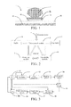
- control system for or the method for controlling the range hood of the present invention may include seven steps comprising Step S 1 to Step S7 in total. After the seven steps, the ultrasonic module of the range hood stays in a normal working state.
- the ultrasonic module 3 includes an MCU 30, an oscillator 31, a first amplifier 32, a shaping circuit 33, an ultrasonic sensor arrangement 34, a first switch 35, a second amplifier 36, a band-pass filter 37, a peak detection circuit 38, and a second switch 39.
- a working principle of the ultrasonic module 3 is that the MCU 30 controls and enables an oscillation frequency of the oscillator 31, a state of the first switch 35 and the second switch 39, and an amplification factor of the second amplifier 36.
- the oscillator 31 is capable of generating a signal of a certain frequency.
- the first amplifier 32 amplifies an output signal of the oscillator 31 to a certain amplitude.
- the shaping circuit 33 shapes the output signal of the first amplifier 32 and outputs the shaped signal to the ultrasonic sensor arrangement 34.
- the ultrasonic sensor arrangement 34 receives an excitation signal output by the shaping circuit 33, sends an acoustic signal and receives a feedback signal.
- the second amplifier 39 amplifies the feedback signal.
- the band-pass filter 37 filters the amplified feedback signal.
- the peak detection circuit 38 extracts a peak voltage from an alternating current (AC) feedback signal and outputs the voltage peak to the MCU 30 for AD sampling.
- AC alternating current
- a device implementing and/or a method for operating the ultrasonic module 3 of the present invention may have the following features.
- two switches are disposed, namely the first switch 35 and the second switch 39.
- the two switches are turned ON/OFF in sequence, therefore effectively reducing an OFF noise input during an amplification process of a small signal. The detailed operation is described as follows.
- Step S30 the oscillator 31 is enabled; the first switch 35 and the second switch 39 are both maintained in an OFF state.
- Step S31 an excitation signal is sent by the oscillator 31; the first amplifier 32 amplifies and sends the excitation signal; and the first switch 35; and the second switch 39 are both maintained in their OFF state.
- Step S32 it is waited for an ultrasonic feedback signal, and the first switch 35 and the second switch 39 are both maintained in the OFF state.
- Step S33 the first switch 35 is turned on; a feedback signal is received; the second amplifier 36 amplifies the feedback signal; and the second switch 39 is maintained in the OFF state.
- Step S34 the second switch 39 is turned on to start AD sampling, and the first switch 35 and the second switch 39 are both maintained in an ON state.
- Step S35 during an idle time, a fan speed is calculated as a function of the sampled data, and the first switch 35 and the second switch 39 are both maintained in the OFF state.
- An ultrasonic system is affected by many factors such as environmental temperature, environmental humidity and fume. These factors may affect the circuit board, the ultrasonic sensors and the ultrasonic signal, so that the received ultrasonic feedback signal changes. For example, when the environmental temperature and the environmental humidity change rapidly, the ultrasonic signal may become too great or too small. As an example, rapid changes of the environmental temperature and the environmental humidity can result in a great value of the ultrasonic signal in a fumeless situation, which may cause a problem, i.e. the amplitude of the ultrasonic signal is too great, and when the fume exists, many sampled ultrasonic signals are saturation values.
- a mean value of the ultrasonic signals is great and a fluctuation interval of the mean value is small, and therefore, it is difficult for the system to determine whether fume exists.
- the rapid changes of the environmental temperature and the environmental humidity can result in a small value of the ultrasonic signal in a fumeless situation, which may cause another problem, i.e. the amplitude of the ultrasonic signal is too small, and the ultrasonic signal fluctuates in a small range no matter fume exists or not. Therefore, it is also difficult for the system to determine whether fume exists.
- the second amplifier 36 is an amplifier having an adjustable amplification factor.
- the amplification factor can be controlled through the MCU 30.
- Such structure in combination with an appropriate system software is capable of solving the problem that the rapid or violent changes of the environmental temperature and the environmental humidity affect the ultrasonic signal.
- Ultrasonic signal threshold values V MAX and V MIN are preset in the MCU 30, and the amplification factor of the second amplifier 36 is adjusted as a function of the sampled actual ultrasonic signals.
- the mean sampled value V MeanValue falls in a reasonable interval, thereby ensuring that the ultrasonic signal is capable of accurately reflecting an influence of the fume.
- FIG. 6a shows a distribution state of sampled values of an ultrasonic signal at a certain fan speed. It can be seen from FIG. 6a that the distribution of the sampled values of the ultrasonic signal is relatively uniform.
- the fan speed also influences the sampled values. Generally speaking, the greater the fan speed is, the greater is the discreteness of the sampled values.
- FIG. 6b shows the influence of the fume on the sampled signals at the same fan speed.
- the sampled values of the ultrasonic signal are relatively concentrated, and the values are relatively great.
- the sampled values of the ultrasonic signal fluctuate in a relatively great range, and the sampled values tend to be low.
- the sampled values of the ultrasonic signal return to the relatively great values and fluctuate in a small range.
- Mean values of the sampled signals are calculated in a certain period, and graphs of the mean values shown in FIG. 7a and FIG. 7b are obtained according to the signals of FIG. 6a and FIG. 6b respectively. Comparing FIG. 7a and FIG. 7b , it can be seen that the influence of the fume on the mean values of the sampled ultrasonic signal leads to a change in the distribution, that is, when no fume exists, the signal curve is relatively smooth and stable; after the fume is generated, since the fume weakens the ultrasonic signal, the amplitude of the curve decreases. Moreover, due to an inhomogeneity of the fume, the signal jumps rapidly, which is reflected by an up-and-down oscillation in the signal curve. Therefore, embodiments of the present invention comprise two approaches for determining the density of the fume as a function of a change of amplitude of the mean value.
- threshold mean values are set for different fan speeds.
- the mean value of the sampled ultrasonic signal is lower than a pre-set threshold value, it is determined that the fan speed needs to be increased.
- the mean value of the sampled ultrasonic signal is higher than a pre-set threshold value, it is determined that the fan speed needs to be decreased.
- threshold values Vspeed1 and Vspeed2 are respectively set for fan speeds Speed1 and Speed2.
- V MeanValue is a mean value of sampled signals in a period between T1 and T2.
- the sampled value V MeanValue ⁇ Vspeed1 the fan speed is increased from tap position 1 to tap position 2.
- the sampled value V MeanValue > Vspeed2 the fan speed is decreased from tap position 2 to tap position 1.
- different mean value fluctuation ranges are pre-set for different fan speeds, and the mean values that exceed the pre-set range are counted over a certain period.
- a pre-set count threshold value is changed for different fan speeds, so as to determine a change of the fan speed.
- different fluctuation range criteria are set for different fan speeds: Speed1 corresponds to an interval (V speed1min , V speed1max ), and Speed2 corresponds to an interval (V speed2min , V speed2max ).
- V MeanValue is a mean value of the sampled signals in a period between T1 and T2.
- V MeanValue of the sampled ultrasonic signals in the period between T1 and T2 exceeds (V speedmin , V speedmax ) by a number of counted values larger than a pre-set criterion C max , it is regarded that the fume is relatively thick, and the fan speed is increased from tap position 1 to tap position 2.
- V MeanValue of the sampled ultrasonic signals in the period between T1 and T2 exceeds (V speedmin , V speedmax ) by a number of counted values smaller than a pre-set criterion C min , it is regarded that the fume is relatively thin, and the fan speed is decreased from tap position 2 to tap position 1.
- An advantage of the first aspect and the second aspect is that valid information of the influence of the fume on the ultrasonic signal is fully extracted using a smart algorithm.
- the two methods may be embodied independently or may be combined according to the specific design of the range hood, thereby allowing an automatic change of the fan speed of the range hood according to the fume state.
Landscapes
- Engineering & Computer Science (AREA)
- Chemical & Material Sciences (AREA)
- Combustion & Propulsion (AREA)
- Mechanical Engineering (AREA)
- General Engineering & Computer Science (AREA)
- Ventilation (AREA)
Applications Claiming Priority (1)
| Application Number | Priority Date | Filing Date | Title |
|---|---|---|---|
| CN201010259003.9A CN102374563B (zh) | 2010-08-17 | 2010-08-17 | 具有烟气自动检测装置的吸油烟机及其控制方法 |
Publications (3)
| Publication Number | Publication Date |
|---|---|
| EP2420741A2 true EP2420741A2 (fr) | 2012-02-22 |
| EP2420741A3 EP2420741A3 (fr) | 2012-07-18 |
| EP2420741B1 EP2420741B1 (fr) | 2014-03-19 |
Family
ID=44654003
Family Applications (1)
| Application Number | Title | Priority Date | Filing Date |
|---|---|---|---|
| EP20110177257 Not-in-force EP2420741B1 (fr) | 2010-08-17 | 2011-08-11 | Système de contrôle pour hotte de cuisine dotée d'un dispositif de détection automatique de fumée |
Country Status (3)
| Country | Link |
|---|---|
| EP (1) | EP2420741B1 (fr) |
| CN (1) | CN102374563B (fr) |
| ES (1) | ES2456499T3 (fr) |
Cited By (5)
| Publication number | Priority date | Publication date | Assignee | Title |
|---|---|---|---|---|
| CN103697517A (zh) * | 2013-12-20 | 2014-04-02 | 广西柳州浚业科技有限公司 | 一种智能变频抽油烟机 |
| CN106861910A (zh) * | 2017-03-31 | 2017-06-20 | 广东美的厨房电器制造有限公司 | 静电装置、油烟机和静电装置的清洗方法 |
| CN107908144A (zh) * | 2017-11-24 | 2018-04-13 | 北京小米移动软件有限公司 | 一种控制抽烟机的方法、装置及存储介质 |
| CN109100276A (zh) * | 2018-10-11 | 2018-12-28 | 四川尚吕家居科技有限公司 | 一种油烟检测系统 |
| CN114526505A (zh) * | 2022-02-24 | 2022-05-24 | 杭州老板电器股份有限公司 | 一种智能按键操控系统、方法及智能家用电器 |
Families Citing this family (2)
| Publication number | Priority date | Publication date | Assignee | Title |
|---|---|---|---|---|
| CN104279598A (zh) * | 2014-11-04 | 2015-01-14 | 成都博盛信息技术有限公司 | 一种智能油烟机 |
| NL2016214B1 (en) * | 2016-02-03 | 2017-08-11 | Intell Properties B V | Cooker hood and power supply arrangement thereof. |
Citations (2)
| Publication number | Priority date | Publication date | Assignee | Title |
|---|---|---|---|---|
| US5074281A (en) | 1990-02-21 | 1991-12-24 | Diehl Gmbh & Co. | Circuit arrangement for the control of a ventilator |
| US6324889B1 (en) | 1998-11-11 | 2001-12-04 | Diehl Stiftung & Co. | Ultrasound sensor for a fumes extractor hood |
Family Cites Families (7)
| Publication number | Priority date | Publication date | Assignee | Title |
|---|---|---|---|---|
| DE4105807A1 (de) * | 1991-02-23 | 1992-08-27 | Diehl Gmbh & Co | Schaltungsanordnung zum ein- und abschalten eines luefters |
| DE19940123A1 (de) * | 1999-08-24 | 2001-03-01 | Bsh Bosch Siemens Hausgeraete | Steuer- oder Regeleinrichtung eines Kochherdes |
| DE20017525U1 (de) * | 2000-10-12 | 2001-01-11 | Taiwan Sakura Corp., Shen Kang, Taichung | Selbststeuernder Schaltkreis eines Rauchabzuges zum Kochen |
| DE10203679A1 (de) * | 2002-01-31 | 2003-08-07 | Diehl Ako Stiftung Gmbh & Co | Steuerung eines elektrischen Lüftermotors einer Dunstabzugshaube |
| DE102004039549A1 (de) * | 2004-08-13 | 2005-11-03 | Miele & Cie. Kg | Dunstabzugshaube zur Absaugung von Kochdunst |
| DE102005015754A1 (de) * | 2004-10-20 | 2006-04-27 | E.G.O. Elektro-Gerätebau GmbH | Lüftungsgerät |
| GB2450967B (en) * | 2007-07-04 | 2009-09-02 | Food Industry Technical Ltd | Air control system and method |
-
2010
- 2010-08-17 CN CN201010259003.9A patent/CN102374563B/zh not_active Expired - Fee Related
-
2011
- 2011-08-11 ES ES11177257.0T patent/ES2456499T3/es active Active
- 2011-08-11 EP EP20110177257 patent/EP2420741B1/fr not_active Not-in-force
Patent Citations (2)
| Publication number | Priority date | Publication date | Assignee | Title |
|---|---|---|---|---|
| US5074281A (en) | 1990-02-21 | 1991-12-24 | Diehl Gmbh & Co. | Circuit arrangement for the control of a ventilator |
| US6324889B1 (en) | 1998-11-11 | 2001-12-04 | Diehl Stiftung & Co. | Ultrasound sensor for a fumes extractor hood |
Cited By (8)
| Publication number | Priority date | Publication date | Assignee | Title |
|---|---|---|---|---|
| CN103697517A (zh) * | 2013-12-20 | 2014-04-02 | 广西柳州浚业科技有限公司 | 一种智能变频抽油烟机 |
| CN106861910A (zh) * | 2017-03-31 | 2017-06-20 | 广东美的厨房电器制造有限公司 | 静电装置、油烟机和静电装置的清洗方法 |
| CN107908144A (zh) * | 2017-11-24 | 2018-04-13 | 北京小米移动软件有限公司 | 一种控制抽烟机的方法、装置及存储介质 |
| EP3489586A1 (fr) * | 2017-11-24 | 2019-05-29 | Beijing Xiaomi Mobile Software Co., Ltd. | Procédé et dispositif de commande de hotte aspirante et support de stockage |
| RU2709445C1 (ru) * | 2017-11-24 | 2019-12-17 | Бейдзин Сяоми Мобайл Софтвэр Ко., Лтд. | Способ и устройство для управления кухонной вытяжкой, а также носитель данных |
| CN107908144B (zh) * | 2017-11-24 | 2020-09-18 | 北京小米移动软件有限公司 | 一种控制抽烟机的方法、装置及存储介质 |
| CN109100276A (zh) * | 2018-10-11 | 2018-12-28 | 四川尚吕家居科技有限公司 | 一种油烟检测系统 |
| CN114526505A (zh) * | 2022-02-24 | 2022-05-24 | 杭州老板电器股份有限公司 | 一种智能按键操控系统、方法及智能家用电器 |
Also Published As
| Publication number | Publication date |
|---|---|
| CN102374563B (zh) | 2015-11-25 |
| EP2420741A3 (fr) | 2012-07-18 |
| ES2456499T3 (es) | 2014-04-22 |
| EP2420741B1 (fr) | 2014-03-19 |
| CN102374563A (zh) | 2012-03-14 |
Similar Documents
| Publication | Publication Date | Title |
|---|---|---|
| EP2420743A1 (fr) | Hotte de cuisine dotée d'un dispositif de détection ultrasonique de fumée et son procédé de contrôle | |
| EP2420741A2 (fr) | Système de contrôle pour hotte de cuisine dotée d'un dispositif de détection automatique de fumée et procédé de contrôle | |
| EP2420742B1 (fr) | Hotte de cuisine dotée d'un dispositif de détection automatique de fumée | |
| CN201340001Y (zh) | 根据油烟浓度自动调节抽风速度的抽油烟机 | |
| CN104329708B (zh) | 近吸式吸油烟机 | |
| CN102589025B (zh) | 一种油烟机的风机转速自适应调节装置的控制方法 | |
| CN113554998B (zh) | 主动降噪装置、室内电器系统及主动降噪方法 | |
| CN106705170A (zh) | 一种控制方法和控制装置 | |
| CN106152218B (zh) | 一种带流量调节的吸油烟机及其流量控制方法 | |
| CN112361415B (zh) | 吸油烟机清洗提醒方法、装置和吸油烟机 | |
| CN202941024U (zh) | 带有语音识别的声控灯 | |
| CN106057189A (zh) | 室内主动降噪装置 | |
| CN110793085A (zh) | 自动检测油烟浓度来控制烟机风量的集成灶及方法 | |
| CN111380097A (zh) | 一种吸油烟机、烟机灶具联动系统及其控制方法 | |
| CN112233673A (zh) | 厨房系统的控制方法、厨房系统和计算机可读存储介质 | |
| CN114440281B (zh) | 一种吸油烟机的控制方法、控制装置及吸油烟机 | |
| CN106839031A (zh) | 一种油烟机的控制方法和控制装置 | |
| CN111156558B (zh) | 具有引流功能油烟机控制方法及油烟机 | |
| CN102518856A (zh) | 利用音频控制开合的开水器节水开关及其方法 | |
| CN211146629U (zh) | 自动检测油烟浓度来控制烟机风量的集成灶 | |
| CN211260932U (zh) | 一种烟灶联动系统 | |
| CN120122535A (zh) | 基于双模检测的嵌入式智能开关控制系统 | |
| CN210091715U (zh) | 一种用于吸油烟机的音量调节系统及其吸油烟机 | |
| CN206593180U (zh) | 节能型抽油烟机 | |
| CN110594174A (zh) | 手持风扇及其控制方法 |
Legal Events
| Date | Code | Title | Description |
|---|---|---|---|
| AK | Designated contracting states |
Kind code of ref document: A2 Designated state(s): AL AT BE BG CH CY CZ DE DK EE ES FI FR GB GR HR HU IE IS IT LI LT LU LV MC MK MT NL NO PL PT RO RS SE SI SK SM TR |
|
| AX | Request for extension of the european patent |
Extension state: BA ME |
|
| PUAI | Public reference made under article 153(3) epc to a published international application that has entered the european phase |
Free format text: ORIGINAL CODE: 0009012 |
|
| PUAL | Search report despatched |
Free format text: ORIGINAL CODE: 0009013 |
|
| AK | Designated contracting states |
Kind code of ref document: A3 Designated state(s): AL AT BE BG CH CY CZ DE DK EE ES FI FR GB GR HR HU IE IS IT LI LT LU LV MC MK MT NL NO PL PT RO RS SE SI SK SM TR |
|
| AX | Request for extension of the european patent |
Extension state: BA ME |
|
| RIC1 | Information provided on ipc code assigned before grant |
Ipc: F24C 15/20 20060101AFI20120611BHEP |
|
| 17P | Request for examination filed |
Effective date: 20130118 |
|
| GRAP | Despatch of communication of intention to grant a patent |
Free format text: ORIGINAL CODE: EPIDOSNIGR1 |
|
| INTG | Intention to grant announced |
Effective date: 20131008 |
|
| GRAS | Grant fee paid |
Free format text: ORIGINAL CODE: EPIDOSNIGR3 |
|
| GRAA | (expected) grant |
Free format text: ORIGINAL CODE: 0009210 |
|
| AK | Designated contracting states |
Kind code of ref document: B1 Designated state(s): AL AT BE BG CH CY CZ DE DK EE ES FI FR GB GR HR HU IE IS IT LI LT LU LV MC MK MT NL NO PL PT RO RS SE SI SK SM TR |
|
| REG | Reference to a national code |
Ref country code: GB Ref legal event code: FG4D |
|
| REG | Reference to a national code |
Ref country code: CH Ref legal event code: EP |
|
| REG | Reference to a national code |
Ref country code: IE Ref legal event code: FG4D |
|
| REG | Reference to a national code |
Ref country code: AT Ref legal event code: REF Ref document number: 657924 Country of ref document: AT Kind code of ref document: T Effective date: 20140415 |
|
| REG | Reference to a national code |
Ref country code: ES Ref legal event code: FG2A Ref document number: 2456499 Country of ref document: ES Kind code of ref document: T3 Effective date: 20140422 |
|
| REG | Reference to a national code |
Ref country code: DE Ref legal event code: R096 Ref document number: 602011005430 Country of ref document: DE Effective date: 20140430 |
|
| PG25 | Lapsed in a contracting state [announced via postgrant information from national office to epo] |
Ref country code: LT Free format text: LAPSE BECAUSE OF FAILURE TO SUBMIT A TRANSLATION OF THE DESCRIPTION OR TO PAY THE FEE WITHIN THE PRESCRIBED TIME-LIMIT Effective date: 20140319 Ref country code: NO Free format text: LAPSE BECAUSE OF FAILURE TO SUBMIT A TRANSLATION OF THE DESCRIPTION OR TO PAY THE FEE WITHIN THE PRESCRIBED TIME-LIMIT Effective date: 20140619 |
|
| REG | Reference to a national code |
Ref country code: NL Ref legal event code: VDEP Effective date: 20140319 |
|
| REG | Reference to a national code |
Ref country code: AT Ref legal event code: MK05 Ref document number: 657924 Country of ref document: AT Kind code of ref document: T Effective date: 20140319 |
|
| REG | Reference to a national code |
Ref country code: LT Ref legal event code: MG4D |
|
| PG25 | Lapsed in a contracting state [announced via postgrant information from national office to epo] |
Ref country code: CY Free format text: LAPSE BECAUSE OF FAILURE TO SUBMIT A TRANSLATION OF THE DESCRIPTION OR TO PAY THE FEE WITHIN THE PRESCRIBED TIME-LIMIT Effective date: 20140319 Ref country code: FI Free format text: LAPSE BECAUSE OF FAILURE TO SUBMIT A TRANSLATION OF THE DESCRIPTION OR TO PAY THE FEE WITHIN THE PRESCRIBED TIME-LIMIT Effective date: 20140319 Ref country code: SE Free format text: LAPSE BECAUSE OF FAILURE TO SUBMIT A TRANSLATION OF THE DESCRIPTION OR TO PAY THE FEE WITHIN THE PRESCRIBED TIME-LIMIT Effective date: 20140319 |
|
| PG25 | Lapsed in a contracting state [announced via postgrant information from national office to epo] |
Ref country code: RS Free format text: LAPSE BECAUSE OF FAILURE TO SUBMIT A TRANSLATION OF THE DESCRIPTION OR TO PAY THE FEE WITHIN THE PRESCRIBED TIME-LIMIT Effective date: 20140319 Ref country code: LV Free format text: LAPSE BECAUSE OF FAILURE TO SUBMIT A TRANSLATION OF THE DESCRIPTION OR TO PAY THE FEE WITHIN THE PRESCRIBED TIME-LIMIT Effective date: 20140319 Ref country code: HR Free format text: LAPSE BECAUSE OF FAILURE TO SUBMIT A TRANSLATION OF THE DESCRIPTION OR TO PAY THE FEE WITHIN THE PRESCRIBED TIME-LIMIT Effective date: 20140319 |
|
| PG25 | Lapsed in a contracting state [announced via postgrant information from national office to epo] |
Ref country code: NL Free format text: LAPSE BECAUSE OF FAILURE TO SUBMIT A TRANSLATION OF THE DESCRIPTION OR TO PAY THE FEE WITHIN THE PRESCRIBED TIME-LIMIT Effective date: 20140319 Ref country code: IS Free format text: LAPSE BECAUSE OF FAILURE TO SUBMIT A TRANSLATION OF THE DESCRIPTION OR TO PAY THE FEE WITHIN THE PRESCRIBED TIME-LIMIT Effective date: 20140719 Ref country code: RO Free format text: LAPSE BECAUSE OF FAILURE TO SUBMIT A TRANSLATION OF THE DESCRIPTION OR TO PAY THE FEE WITHIN THE PRESCRIBED TIME-LIMIT Effective date: 20140319 Ref country code: BG Free format text: LAPSE BECAUSE OF FAILURE TO SUBMIT A TRANSLATION OF THE DESCRIPTION OR TO PAY THE FEE WITHIN THE PRESCRIBED TIME-LIMIT Effective date: 20140619 Ref country code: BE Free format text: LAPSE BECAUSE OF FAILURE TO SUBMIT A TRANSLATION OF THE DESCRIPTION OR TO PAY THE FEE WITHIN THE PRESCRIBED TIME-LIMIT Effective date: 20140319 Ref country code: CZ Free format text: LAPSE BECAUSE OF FAILURE TO SUBMIT A TRANSLATION OF THE DESCRIPTION OR TO PAY THE FEE WITHIN THE PRESCRIBED TIME-LIMIT Effective date: 20140319 Ref country code: EE Free format text: LAPSE BECAUSE OF FAILURE TO SUBMIT A TRANSLATION OF THE DESCRIPTION OR TO PAY THE FEE WITHIN THE PRESCRIBED TIME-LIMIT Effective date: 20140319 |
|
| PG25 | Lapsed in a contracting state [announced via postgrant information from national office to epo] |
Ref country code: PL Free format text: LAPSE BECAUSE OF FAILURE TO SUBMIT A TRANSLATION OF THE DESCRIPTION OR TO PAY THE FEE WITHIN THE PRESCRIBED TIME-LIMIT Effective date: 20140319 Ref country code: SK Free format text: LAPSE BECAUSE OF FAILURE TO SUBMIT A TRANSLATION OF THE DESCRIPTION OR TO PAY THE FEE WITHIN THE PRESCRIBED TIME-LIMIT Effective date: 20140319 Ref country code: AT Free format text: LAPSE BECAUSE OF FAILURE TO SUBMIT A TRANSLATION OF THE DESCRIPTION OR TO PAY THE FEE WITHIN THE PRESCRIBED TIME-LIMIT Effective date: 20140319 |
|
| REG | Reference to a national code |
Ref country code: DE Ref legal event code: R097 Ref document number: 602011005430 Country of ref document: DE |
|
| PG25 | Lapsed in a contracting state [announced via postgrant information from national office to epo] |
Ref country code: PT Free format text: LAPSE BECAUSE OF FAILURE TO SUBMIT A TRANSLATION OF THE DESCRIPTION OR TO PAY THE FEE WITHIN THE PRESCRIBED TIME-LIMIT Effective date: 20140721 |
|
| PLBE | No opposition filed within time limit |
Free format text: ORIGINAL CODE: 0009261 |
|
| STAA | Information on the status of an ep patent application or granted ep patent |
Free format text: STATUS: NO OPPOSITION FILED WITHIN TIME LIMIT |
|
| PG25 | Lapsed in a contracting state [announced via postgrant information from national office to epo] |
Ref country code: DK Free format text: LAPSE BECAUSE OF FAILURE TO SUBMIT A TRANSLATION OF THE DESCRIPTION OR TO PAY THE FEE WITHIN THE PRESCRIBED TIME-LIMIT Effective date: 20140319 |
|
| 26N | No opposition filed |
Effective date: 20141222 |
|
| REG | Reference to a national code |
Ref country code: CH Ref legal event code: PFA Owner name: BSH HAUSGERAETE GMBH, DE Free format text: FORMER OWNER: BSH BOSCH UND SIEMENS HAUSGERAETE GMBH, DE |
|
| PG25 | Lapsed in a contracting state [announced via postgrant information from national office to epo] |
Ref country code: LU Free format text: LAPSE BECAUSE OF FAILURE TO SUBMIT A TRANSLATION OF THE DESCRIPTION OR TO PAY THE FEE WITHIN THE PRESCRIBED TIME-LIMIT Effective date: 20140811 Ref country code: MC Free format text: LAPSE BECAUSE OF FAILURE TO SUBMIT A TRANSLATION OF THE DESCRIPTION OR TO PAY THE FEE WITHIN THE PRESCRIBED TIME-LIMIT Effective date: 20140319 |
|
| REG | Reference to a national code |
Ref country code: CH Ref legal event code: PL |
|
| REG | Reference to a national code |
Ref country code: DE Ref legal event code: R097 Ref document number: 602011005430 Country of ref document: DE Effective date: 20141222 |
|
| PG25 | Lapsed in a contracting state [announced via postgrant information from national office to epo] |
Ref country code: LI Free format text: LAPSE BECAUSE OF NON-PAYMENT OF DUE FEES Effective date: 20140831 Ref country code: CH Free format text: LAPSE BECAUSE OF NON-PAYMENT OF DUE FEES Effective date: 20140831 |
|
| REG | Reference to a national code |
Ref country code: IE Ref legal event code: MM4A |
|
| REG | Reference to a national code |
Ref country code: DE Ref legal event code: R081 Ref document number: 602011005430 Country of ref document: DE Owner name: BSH HAUSGERAETE GMBH, DE Free format text: FORMER OWNER: BSH BOSCH UND SIEMENS HAUSGERAETE GMBH, 81739 MUENCHEN, DE Effective date: 20150409 |
|
| REG | Reference to a national code |
Ref country code: ES Ref legal event code: PC2A Owner name: BSH HAUSGERATE GMBH Effective date: 20150529 |
|
| PG25 | Lapsed in a contracting state [announced via postgrant information from national office to epo] |
Ref country code: SI Free format text: LAPSE BECAUSE OF FAILURE TO SUBMIT A TRANSLATION OF THE DESCRIPTION OR TO PAY THE FEE WITHIN THE PRESCRIBED TIME-LIMIT Effective date: 20140319 |
|
| REG | Reference to a national code |
Ref country code: FR Ref legal event code: PLFP Year of fee payment: 5 |
|
| PG25 | Lapsed in a contracting state [announced via postgrant information from national office to epo] |
Ref country code: IE Free format text: LAPSE BECAUSE OF NON-PAYMENT OF DUE FEES Effective date: 20140811 |
|
| REG | Reference to a national code |
Ref country code: FR Ref legal event code: CD Owner name: BSH HAUSGERATE GMBH, DE Effective date: 20151022 |
|
| PG25 | Lapsed in a contracting state [announced via postgrant information from national office to epo] |
Ref country code: SM Free format text: LAPSE BECAUSE OF FAILURE TO SUBMIT A TRANSLATION OF THE DESCRIPTION OR TO PAY THE FEE WITHIN THE PRESCRIBED TIME-LIMIT Effective date: 20140319 |
|
| PG25 | Lapsed in a contracting state [announced via postgrant information from national office to epo] |
Ref country code: GR Free format text: LAPSE BECAUSE OF FAILURE TO SUBMIT A TRANSLATION OF THE DESCRIPTION OR TO PAY THE FEE WITHIN THE PRESCRIBED TIME-LIMIT Effective date: 20140620 Ref country code: MT Free format text: LAPSE BECAUSE OF FAILURE TO SUBMIT A TRANSLATION OF THE DESCRIPTION OR TO PAY THE FEE WITHIN THE PRESCRIBED TIME-LIMIT Effective date: 20140319 |
|
| PG25 | Lapsed in a contracting state [announced via postgrant information from national office to epo] |
Ref country code: HU Free format text: LAPSE BECAUSE OF FAILURE TO SUBMIT A TRANSLATION OF THE DESCRIPTION OR TO PAY THE FEE WITHIN THE PRESCRIBED TIME-LIMIT; INVALID AB INITIO Effective date: 20110811 Ref country code: TR Free format text: LAPSE BECAUSE OF FAILURE TO SUBMIT A TRANSLATION OF THE DESCRIPTION OR TO PAY THE FEE WITHIN THE PRESCRIBED TIME-LIMIT Effective date: 20140319 |
|
| REG | Reference to a national code |
Ref country code: FR Ref legal event code: PLFP Year of fee payment: 6 |
|
| REG | Reference to a national code |
Ref country code: FR Ref legal event code: PLFP Year of fee payment: 7 |
|
| PG25 | Lapsed in a contracting state [announced via postgrant information from national office to epo] |
Ref country code: MK Free format text: LAPSE BECAUSE OF FAILURE TO SUBMIT A TRANSLATION OF THE DESCRIPTION OR TO PAY THE FEE WITHIN THE PRESCRIBED TIME-LIMIT Effective date: 20140319 |
|
| REG | Reference to a national code |
Ref country code: FR Ref legal event code: PLFP Year of fee payment: 8 |
|
| PG25 | Lapsed in a contracting state [announced via postgrant information from national office to epo] |
Ref country code: AL Free format text: LAPSE BECAUSE OF FAILURE TO SUBMIT A TRANSLATION OF THE DESCRIPTION OR TO PAY THE FEE WITHIN THE PRESCRIBED TIME-LIMIT Effective date: 20140319 |
|
| PGFP | Annual fee paid to national office [announced via postgrant information from national office to epo] |
Ref country code: ES Payment date: 20180921 Year of fee payment: 8 Ref country code: IT Payment date: 20180823 Year of fee payment: 8 Ref country code: FR Payment date: 20180824 Year of fee payment: 8 Ref country code: DE Payment date: 20180831 Year of fee payment: 8 |
|
| PGFP | Annual fee paid to national office [announced via postgrant information from national office to epo] |
Ref country code: GB Payment date: 20180828 Year of fee payment: 8 |
|
| REG | Reference to a national code |
Ref country code: DE Ref legal event code: R119 Ref document number: 602011005430 Country of ref document: DE |
|
| GBPC | Gb: european patent ceased through non-payment of renewal fee |
Effective date: 20190811 |
|
| PG25 | Lapsed in a contracting state [announced via postgrant information from national office to epo] |
Ref country code: DE Free format text: LAPSE BECAUSE OF NON-PAYMENT OF DUE FEES Effective date: 20200303 Ref country code: FR Free format text: LAPSE BECAUSE OF NON-PAYMENT OF DUE FEES Effective date: 20190831 |
|
| PG25 | Lapsed in a contracting state [announced via postgrant information from national office to epo] |
Ref country code: IT Free format text: LAPSE BECAUSE OF NON-PAYMENT OF DUE FEES Effective date: 20190811 Ref country code: GB Free format text: LAPSE BECAUSE OF NON-PAYMENT OF DUE FEES Effective date: 20190811 |
|
| REG | Reference to a national code |
Ref country code: ES Ref legal event code: FD2A Effective date: 20210105 |
|
| PG25 | Lapsed in a contracting state [announced via postgrant information from national office to epo] |
Ref country code: ES Free format text: LAPSE BECAUSE OF NON-PAYMENT OF DUE FEES Effective date: 20190812 |