EP2420748A2 - Procédé et système d'exécution d'une égalisation hydraulique dans un système de chauffage - Google Patents
Procédé et système d'exécution d'une égalisation hydraulique dans un système de chauffage Download PDFInfo
- Publication number
- EP2420748A2 EP2420748A2 EP11006715A EP11006715A EP2420748A2 EP 2420748 A2 EP2420748 A2 EP 2420748A2 EP 11006715 A EP11006715 A EP 11006715A EP 11006715 A EP11006715 A EP 11006715A EP 2420748 A2 EP2420748 A2 EP 2420748A2
- Authority
- EP
- European Patent Office
- Prior art keywords
- value
- temperature
- heating surface
- opening position
- heating
- Prior art date
- Legal status (The legal status is an assumption and is not a legal conclusion. Google has not performed a legal analysis and makes no representation as to the accuracy of the status listed.)
- Withdrawn
Links
Images


Classifications
-
- F—MECHANICAL ENGINEERING; LIGHTING; HEATING; WEAPONS; BLASTING
- F24—HEATING; RANGES; VENTILATING
- F24D—DOMESTIC- OR SPACE-HEATING SYSTEMS, e.g. CENTRAL HEATING SYSTEMS; DOMESTIC HOT-WATER SUPPLY SYSTEMS; ELEMENTS OR COMPONENTS THEREFOR
- F24D19/00—Details
- F24D19/10—Arrangement or mounting of control or safety devices
- F24D19/1006—Arrangement or mounting of control or safety devices for water heating systems
- F24D19/1009—Arrangement or mounting of control or safety devices for water heating systems for central heating
- F24D19/1015—Arrangement or mounting of control or safety devices for water heating systems for central heating using a valve or valves
- F24D19/1018—Radiator valves
Definitions
- the invention relates to a method and a system for performing a hydraulic balancing in a heating system with at least two heating surfaces, in particular at least two radiators, wherein the mass flow of a heating fluid through each of the heating surfaces on each of the heating surfaces by means of an electronic thermostatic valve individually by adjusting the current opening position of Thermostat valve is controlled, wherein for each of the heating surfaces of temperature readings a value representing the operating point of the heating surface determined and compared with a stored comparison value of the heating surface and depending on the comparison, the maximum permissible opening position of the thermostatic valve is electronically limited.
- a system for carrying out such a method comprises at least one heating surface through which a heating fluid flows, in particular at least one heating element, each heating surface having an electronic thermostatic valve for regulating the mass flow through the heating surface as a function of the room temperature.
- each electronic thermostatic valve has its own control, eg internally in the valve or by an external control to set the opening position of the valve based on the room air setpoint temperature preset by a user and the measured room air temperature and so the room air temperature to regulate. It can communicate for this purpose, several thermostatic valves with a higher-level control unit.
- a plurality of heating surfaces are arranged in a circuit with a heat generator, e.g. a central heating to supply the individual heating surfaces each with heated heating fluid.
- a heat generator e.g. a central heating to supply the individual heating surfaces each with heated heating fluid.
- These can be single-pipe or twin-pipe systems.
- the heat generator e.g. a gas or oil heating or district heating device, a heating fluid of a predetermined flow temperature available, then it is ensured by one or more circulation pumps that each of the heating surfaces is flowed through in the heating system of the heating fluid with the selected flow temperature.
- the flow temperature may e.g. be outside temperature-controlled, have a night-time lowering or other basically follow any criteria, e.g. are stored by characteristic curves in a heating system.
- the individual heating surfaces can have different flow resistance within such a heating system in connection with the pipes leading to the individual heating surfaces. It follows, in particular with simultaneously opened thermostatic valves of several radiators that a heating surface with a higher flow resistance has a lower mass flow of the heating fluid than a heating surface with a lower flow resistance.
- heating phases of a heating system as they occur, for example, after a reduction in the flow temperature during the night after the end of the night setback, but also during the time of night reduction, this may result in heating surfaces with a lower flow resistance creates a high mass flow of heating fluid, In contrast, only a small mass flow of heating fluid at such heating surfaces with a higher flow resistance, so that found in the latter heating surfaces, in particular space heaters, a hydraulic undersupply is, however, in the former heating surfaces or radiators a hydraulic oversupply. This is especially true when this is usually several or even all the thermostatic valves of the heating surfaces of the heating system are open.
- Such a hydraulic adjustment is usually carried out by the fact that the flow resistance is set individually by a heating engineer when installing the system on each heating surface or in certain strand sections of the heating system, especially if all thermostatic valves of the heating surfaces are opened.
- the flow resistance in the return fitting of radiators can be variably adjusted or it can be changed by a so-called presetting of the flow cross-section in radiator valves, in particular gradually.
- Another disadvantage is that a one-time performed hydraulic balancing is performed for one operating point. As an operating point usually the design state is taken, are based on the minimum outside temperature conditions. However, as these design conditions rarely occur in practice, it is quite possible that the one-time hydraulic balancing will only produce suboptimal results for much of the plant's operating life.
- a method and system for performing an automatic hydraulic balancing in a heating system is eg from the publication DE 199 11 866 A1 known. From this it is known to determine the operating point of each heating surface by the difference of the temperatures of flow and return and adjust to a desired value as a comparison value by changing the opening of a valve of each heating circuit. An additional room thermostat closes the valve when the room temperature has reached a setpoint or open when the setpoint is not reached.
- a heat demand adjustment of the opening positions of the thermostatic valves should be achieved, for example, to minimize the target-actual deviation in the room air temperature.
- this object is achieved in that in a case when the comparison indicates a hydraulic over-supply of the heating surface, the current opening position of the thermostatic valve by a reduction value, in particular a fixed reduction value, in particular repeatedly reduced until the comparison provides a result, according to which a further reduction is unnecessary and the value of the last opening position is stored as the maximum permissible opening position together with the measured excess temperature of the heating surface for the formation and / or adaptation of a characteristic / a characteristic field.
- a system for carrying out such a method is accordingly arranged, in a case when the comparison indicates a hydraulic oversupply of the respective heating surface, to reduce the current opening position of the thermostatic valve by a reduction value, in particular a fixed reduction value, in particular several times until the comparison yields a result according to which a further reduction is unnecessary and to store the value of the last opening position as the maximum permissible opening position together with the measured excess temperature of the heating surface for the formation and / or adaptation of a characteristic / a characteristic field.
- a value is determined for the implementation of the method or in a system purely from temperature measured values which can be detected at any time during operation of the system by means of temperature sensors, which represents an operating point of the considered heating surface. It then suffices a simple comparison to obtain a hydraulic balance. Depending on the type of value determined and the reference value used, a limit will then be set performed, for example, if the value exceeds the comparison value or alternatively falls short of.
- Such a value may be obtained from the detected temperature readings, e.g. are determined on the basis of a stored model, in particular a stored calculation rule, in a calculation device or also result directly from the temperature measurement values, e.g. by summation or difference value formation.
- a stored comparison value which, based on the calculated value mentioned in the introduction, e.g. is formed by a standard design value of the heating surface or a value dependent thereon.
- it may be provided to select from a plurality of different possible values in order to represent an operating point of the heating surface.
- the current or time filtered mass flow (e.g., mean) flowing through the heating surface may be used, which is calculated from a stored model.
- comparison value e.g. a limit mass flow should be used, which should not be exceeded at the considered heating surface and is stored for the heating surface, e.g. in the computing device.
- This comparison value may be e.g. given by the standard mass flow at the design point of the radiator or a value dependent thereon.
- the comparative value in particular the said limiting mass flow, may itself be dependent on at least one of the measured temperatures, e.g. from the excess temperature of the heating surface, in particular which here denotes the difference between flow and room temperature. It can therefore be provided to determine the comparison value from a table, characteristic curve or calculation rule for the comparison as a function of the temperature, e.g. also in the calculation device.
- the heat output current or filtered from the heating surface may be determined as a value, e.g. again using a stored model.
- a stored comparison value e.g. the standard heat output at the design point of the radiator or a dependent value or the theoretically maximum achievable heating power of the radiator are used.
- the maximum heating power e.g. by means of limiting value formation when the mass flow approaches infinity.
- the return temperature is equal to the flow temperature.
- a value dependent on the maximum possible heating power For example, one could demand that the current heating power does not exceed a value of 90% of the maximum possible heating power at the operating point.
- the current or filtered slope of the radiator performance vs. mass flow or radiator performance versus valve lift characteristic may be used, particularly where the slope is calculated from a stored model.
- This slope-based design is based on the consideration that the radiator performance is non-linear and results in a flattening of the power curve for high mass flows or even large valve lifts, thus their slope decreases sharply.
- the slope of a desired operating point is set for the process, which should not be exceeded during operation.
- a comparison value such a limit gradient can be determined as a function of the slope of the radiator performance curve at the design point. For example, can be determined as the limit slope that slope, which is present at twice the design mass flow. At least the limit slope should be less than or equal to the slope at the design point. We found in the comparison that the current or filtered slope is smaller than the comparison value, so again the inventive limitation of the maximum permissible opening position.
- the temperature spread of the heating surface ie the difference between the flow and return of the heating surface by measuring the flow and return temperature is determined.
- the current or filtered spread can be compared to a comparison value. If the spread is smaller than the comparison value, then the limitation occurs.
- the comparison value can be determined here, for example, based on a limiting mass flow, as was mentioned for the first embodiment.
- the return temperature can also be any other state variable of the radiator such as the radiator temperature to 75% of the height of the radiator used to determine a spread.
- the core idea of the invention is based on avoiding that the considered heating surface with respect to the calculated value, which represents the operating point, does not exceed or fall short of the stored or computable comparison value, depending on which value is used, since it is known that this is due to known Nonlinearities of a heating surface no further advantage in the heating of rooms is achieved, but a drawback is to recognize that otherwise the remaining heating surfaces of the heating system are hydraulically and thus energetically underserved.
- the mass flow flowing through the heating surface is greater than the limiting mass flow for which the heating surface is aligned or the value of the heat output is greater than the limit heat output of the heating surface or the slope is smaller than the limit slope or the spread is smaller than the boundary spread so there is an automatic limitation of the maximum permissible opening position of the thermostatic valve, thereby increasing the flow resistance of the considered heating surface and thus the maximum possible heat output, based on a design flow temperature or the maximum by this heating surface flowing mass flow of the heating fluid is limited in the same way.
- each considered thermostatic valve is carried out electronically, so that this limit autonomous, e.g. can be made by the heating system or the thermostat valve itself, without the need for a human intervention.
- the limitation is such that a current opening position of a thermostatic valve currently to be tested in the method when a hydraulic oversupply is detected is gradually reduced with each limitation, e.g. by an absolute amount or by a relative amount, e.g. by a certain percentage.
- each limitation e.g. by an absolute amount or by a relative amount, e.g. by a certain percentage.
- iteration for example, if, after a performance, in particular after a prescribed rest period, there is still a hydraulic overfeed
- there is a limit in each iteration step until the monitored value withstands the comparison thus no further limitation is necessary becomes.
- the maximum permissible opening position is limited at the present excess temperature.
- a thermostatic valve of at least some, preferably all heating surfaces of such a heating system its opening cross section can only change so far that this is turned on due to the electronic limit at most up to the electronically fixed, maximum allowable opening position, but not beyond even if the considered thermostatic valve could allow even further opening purely due to its physically given possibilities. This further opening is prevented by the electronic limitation.
- thermostatic valve in an individual room control for regulating the room temperature by means of a thermostatic valve on a respective heating surface of this room only one such opening position of the thermostatic valve is allowed within its control, which between the maximum closed position or a minimum frost protection position and the maximum opening position determined in the course of the calculation and the comparison.
- the current opening position of a thermostatic valve can be detected by metrology, for example by measuring the stroke of the valve actuator, for example by means of strain gauges or in a similar manner, by an electronic feedback of the valve actuator or by evaluating the manipulated variable of the electronic room temperature controller.
- the current opening position can be determined at any time.
- a thermostatic valve or the system may comprise an electronically interrogatable memory in which the maximum permissible opening position is stored and may be changed after calculation, e.g. by overwriting the old value with a new one.
- a characteristic curve or at least one characteristic diagram with discrete value pairs can be formed by the plurality of value pairs of excess temperature and permissible opening position stored over time ,
- the opening position can be further limited by the comparison described above, if there is a hydraulic oversupply or the opening position is increased, if a shortage is given. Then, the thus determined new opening position can be stored as a new maximum permissible opening position in the map / the characteristic at the associated excess temperature, whereby the characteristic / the map is adapted and updated.
- the fulfillment or non-fulfillment of the comparison can be checked by whether the value representing the operating point lies within a given tolerance around the comparison value or not. If the tolerance is exceeded, then this state is considered to be not hydraulically balanced, in particular depending on the direction of exceeding as over- or undersupplied.
- a function to the stored value pairs, in particular if at least two or more than two value pairs are present, e.g. by a step function or exponential function or polynomial or other suitable function, e.g. also by a straight line.
- the above-mentioned value is calculated by solving the static or dynamic radiator equation as a function of a plurality of measured temperatures.
- the radiator equation known to those skilled in the art further parameters, such as e.g. enter the heat transfer coefficient of the heating surface and / or the radiator exponent.
- Such parameters may be variable, i. be predeterminable or be taken into account in the equation for a calculation.
- the heat output of the heating surface, the slope or the spread, the flow temperature and / or the room air temperature of the space heated by the heating surface and the heating surface area can be determined with reference to the considered heating surface. and / or the return temperature and / or the outside temperature are measured, for which in the said system for performing the method corresponding temperature sensors on the flow of the heating surface and / or on the flow of the heating strand and / or on the return of the heating surface and / or in space and / or directly can be arranged on the heating surface and / or on the outer shell of the building.
- the flow temperature can be assigned by the heating curve clearly an outside temperature.
- outside temperature instead of the difference between supply and room temperature
- room temperature instead of the difference between supply and room temperature
- Such temperature sensors may be provided separately in a system according to the invention or in the implementation of the method, but preferably sensors are used, which are already present on components of the heating system, such as on the radiator (eg in a heat cost allocator) or on the thermostatic valve.
- the room air temperature and alternatively either the Schund- or return temperature can be calculated via the aforementioned radiator equation of the method to be considered value and then compared with the comparison value.
- a respective heating surface has a heat cost allocator, which is usually used to detect the heat output to the relevant heating surface and to count an internal counter depending on the heat output, so in particular over a billing period, the total incurred heating costs among the individual Be able to distribute parties to a property.
- Such a heat cost allocator can already be present and used for the interests of the invention, by providing at least a part of the total required temperature measured values for the calculation.
- such a heat cost allocator or smoke detector can preferably be used to measure in particular with one of its temperature sensors, for example, the room air temperature in the space of the considered heating surface or also (in the case of Schumacherers) the room air temperature from the measured Schundtemperatur to extrapolate.
- the Schundtemperatur with such a heat cost allocator or its Temperature sensor is detected, are used.
- the room air temperature can be detected by a separate room air temperature sensor, eg also a smoke detector.
- the flow and / or return temperature and / or room air temperature are measured by temperature sensors of the respective thermostatic valve and the Schuvin- and / or return temperature and / or room air temperature by a temperature sensor of a the heating surface associated heating cost allocator is measured and / or the room air temperature is measured by a smoke alarm.
- thermostatic valve and heat cost allocator and / or smoke detectors complement in such a system according to the invention insofar as to calculate the respective value of interest, such as the mass flow or the heat output of the heating surface, the slope or spreading the necessary temperature readings each to a part of both System units, ie Thermostat valve and heat cost allocators and / or smoke detectors are contributed.
- the heating surface and / or return temperature of the respective heat cost allocator. is communicated by radio to the respective thermostatic valve and the calculation of the value of interest on the basis of at least one further, contributed by the thermostatic valve temperature reading, in particular the flow temperature, by means of the stored model, e.g. is made by the thermostatic valve.
- the room air temperature may e.g. be communicated by radio from a smoke detector to the thermostatic valve.
- the thermostatic valve has an internal intelligence, eg a microprocessor with a program running therein, by means of which the Calculation, for example, based on a stored model and the total provided temperature readings is made, in this embodiment by a receiving unit of the thermostatic valve from the outside at least one temperature reading is detected by the arranged in the vicinity of the thermostatic valve heat cost allocator.
- the thermostatic valve comprises a computing device.
- the transmission of the measured value by radio can in principle be used in the heat cost allocator and / or smoke detector anyway existing transmitting device that is otherwise commonly used to send the internal meter readings of the heat cost allocator for the purpose of "reading", e.g. to stationary or mobile receiving units.
- a separate transmitting device may be provided in the heat cost allocator to communicate temperature readings to the thermostatic valve.
- the flow and / or room air temperature for example, from the thermostatic valve and / or a smoke detector to the heat cost allocator, in particular by radio are communicated and the calculation, for example, based on a stored Model is made by the heat cost allocator, what then this includes a calculation device and then back to the calculation and a comparison, a value for limiting the maximum permissible opening position back to the thermostatic valve, in particular again by radio.
- the electronic intelligence in particular in the form of a microprocessor, is provided by the heat cost allocator, thus making the calculation on the basis of the temperature measured values provided, but then, in contrast to the previous embodiment, the maximum permissible opening position representing value to the thermostatic valve communicates.
- thermostatic valve has the Computationsintelligencez and insofar as an optionally recalculated maximum permissible opening value of the thermostatic valve after calculation is present directly in the thermostatic valve and can be used for the electronic limitation, for. by storing in a designated memory area.
- the temperature readings from an electronic thermostatic valve and / or the heat cost allocator to a separate, e.g. central computing device, e.g. by radio or wired. It can be e.g. be a computing device that is integrated into a network with thermostatic valves and / or heat cost allocators of the respective heating surfaces or an external data center.
- This calculation device comprises the stored model and calculates the said value, eg the mass flow through the considered heating surface or its heat dissipation or the slope or the spread for the purpose of the comparison.
- the respective comparison value can eg in the Calculation device for all connected heating surfaces or for the purpose of comparison of the thermostatic valve or the heat cost allocator of each heating surface are also provided by communication to the computing device. If the calculation device determines in the context of the comparison that the maximum permissible opening position is to be limited, it communicates a corresponding new value for limiting back to the respective thermostatic valve.
- a calculation may e.g. are made of a plurality of during the aforementioned predetermined time period and / or collected before the said time temperature readings.
- the temperature measurements required for the calculation may be of a smaller periodicity than the predetermined period, e.g. be detected over a day several times, the limitation of the maximum opening position and thus, e.g. the writing of a value representing this position in the thermostatic valve in a designated memory area, however, takes place only with the periodicity mentioned above, such as once a day. This reduces an optionally disadvantageous, too frequent change of the flow resistance within a heating system.
- the maximum permissible opening position is limited only when exceeding (or falling below, depending on the value / comparison value), in particular a multiple Exceeding / undershooting is detected by a stored limit value and / or beyond a preset time interval.
- this ensures that a limitation does not occur immediately in the case of a single or even a very small exceeding / undershooting of the comparison value by the calculated value, but in one embodiment only when this exceeding / falling below a certain order of magnitude exceeds the limit / Thus falls short of a certain, stored as a limit value takes place and / or multiple times and / or takes place over a certain period.
- thermostatic valve When limiting the maximum permissible opening position of the thermostatic valve, it may be provided that to maintain a minimum mass flow downwards, a minimum opening position is not exceeded. Thus, functions such as the protection against freezing can be ensured by such a minimum mass flow generated thereby.
- the maximum permissible opening position after a previous limitation i. Reduction is in turn increased, in particular if the value resulting from the calculation based on the stored model, the comparison value falls below (or exceeds, depending on the selected value / comparison value), in particular in an analogous manner, as mentioned above, by a predetermined limit falls below / exceeds and / or falls short of / exceeds for the duration of a preset time interval.
- the method according to the invention does not necessarily always only reduce the maximum permissible opening position that the thermostatic valve is allowed to assume, so that changing flow conditions resulting from changed conditions in the entire heating system can also be taken into account.
- a pump used in the heating system will deliver its entire mass flow through a heating surface with a wide open thermostatic valve, so here the method of the invention is highly probable determines an over-supply condition by calculating the value to be used and comparison, and electronically limits the maximum opening position of the thermostatic valve of this over-supplied heating surface.
- the maximum permissible opening position of the thermostatic valve at a certain heating surface is not a constant value, but depends on conditions in the heating system and, for. for the described state, in turn, can be increased without the risk of oversupply this heating surface and a shortage of other heating surfaces is given.
- the invention can also be provided, after determining the operating point at a certain time on the basis of the value representing the operating point to calculate this value temporally in the future, in particular on the basis of a stored model taking into account the dynamic behavior of the system and then the projected value to use for comparison rather than the current value.
- This can take into account the fact that in a dynamically changing heating system at the time of measurement of the temperatures for the determination of the operating point is not a statically stable state.
- the extrapolation converts the currently changing operating point into a future static operating point.
- a calculation rule can be stored in the system with which this extrapolation takes place.
- the rule may e.g. created in the system design.
- heat cost allocators which were otherwise used only in terms of their function for heating cost distribution, can make a further contribution to energy conservation, namely the fact that they contribute to the implementation of the method within the system according to the invention insofar as they at least provide a temperature measurement required for the calculation available, for example, the room air temperature and / or the Schundtemperatur and / or the return temperature of the heating surface.
- a system can thus be set up such that it has a heat cost allocator on the heating surface for detecting the heat output the heating surface, wherein at least one of the devices is arranged by the thermostatic valve or heat cost allocator to make the aforementioned comparison by the calculation on the basis of a stored model with the aid of at least one measured by said device itself temperature reading and at least one of the other device by preferred radio communication transmitted temperature reading.
- the communication of the supplied temperature measured value for example, also be wired.
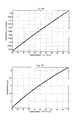
- FIG. 1 shows a graphical representation of several characteristics of a assumed for this embodiment combination of a heating surface with an electronic thermostatic valve.
- the assumptions for this embodiment are only for specific description, without limiting the possible embodiments to this example.
- valve characteristic is used in this embodiment to clarify the technical context and for the simulative description of a possible real-world scenario to prove the function of the invention.
- the characteristics of the FIG. 1 in particular such a valve characteristic of Figure 1A neither needed nor is it necessary to determine the characteristic curves.
- FIG. 1B an exemplary characteristic of the radiator is shown on the one hand at 75 ° C and on the other hand at 50 ° C flow temperature and 20 ° C room temperature, which represents the relationship between the heat output of this radiator depending on the mass flow through this radiator.
- the square marks the standard design condition at 75 ° C / 65 ° C / 20 ° C, ie the point at which the return temperature of 65 ° C is 75 ° C. In the design point, therefore, the considered radiator has a certain standard design value of the mass flow, in this example of 0.0364kg / s.
- the Figure 1C shows each exemplary characteristics resulting from a series connection of a valve with the characteristic according to Figure 1A and a radiator according to FIG. 1B result. These show the heat output of the radiator depending on the valve lift. Based on the characteristic curve for the supply temperature of 75 ° C, it can be seen that the standard design point of the radiator has already been reached at approx. 19% of the valve position. From this low value of the valve position, it can be seen that this is a hydraulically overheated radiator.
- radiator characteristic eg according to the FIG. 1B and requires that during operation, for example, a reference value, once defined, of a minimum gradient of the radiator characteristic, in particular that at the flow temperature at the design point (in this case 75 ° C.), not be undershot.
- the mathematical symbols used are listed in Table 1 below. ⁇ b> Table 1: Mathematical Symbols and Availability.
- the slope depends on the radiator parameters, the overtemperature and the mass flow. It can thus be determined by this equation for each mass flow at the given (measured) temperatures, the slope of the radiator characteristic and inversely to the selected reference value of the slope, a mass flow limit at the given (measured) temperatures are determined, which should be below the reference value the slope not to fall below.
- the current mass flow can be reconstructed according to the invention from the known or measured temperatures, the radiator parameters and possibly the current valve position with standard tools of control engineering and system identification using a stored model.
- a calculation of the mass flow ⁇ according to the invention is possible. From multiple measurements, mean values or filtered mass flow values can also be determined.
- the slope of the current operating point can be determined (estimated). For the automated hydraulic balancing according to the invention, this means that in this embodiment the estimate of the current gradient can be compared with the selected gradient reference value at any time.
- a reference value a value smaller than the slope at the design point or at least one reference value dependent on the slope at the design point is preferably selected here.
- the value representing the operating point of the heating surface may be the slope at the operating point of the heating surface and the comparison value given by the reference value of the slope mentioned here.
- an iterative solution method can be carried out for determining the limiting mass flow by means of the aforementioned equation, since this equation can not be explicitly solved for ⁇ .
- the characteristic curve for the limiting mass flow depends only on the known radiator parameters ⁇ , n and the eg once defined limit slope dQ ⁇ min ld ⁇ . This allows an a-priori calculation of the characteristic curve for the limiting mass flow, in particular that is deposited once during the installation of the system in the microcontroller, for example, the calculation device mentioned above. Alternatively, it is possible to transfer the characteristic from a central IT, preferably by radio, into the system according to the invention and, if necessary, to update it.
- a mass flow value e.g. the current mass flow is compared with the determined limit mass flow, without necessarily determining slope values beforehand.
- the mass flow currently flowing through the radiator can be determined, for example, by means of a static or dynamic radiator model.
- Table 2 Table 2: Mathematical Symbols and Availability. ⁇ / b> symbol importance Availability ⁇ log ( t ) Logarithmic overtemperature known, measured m HK Mass of the radiator known C HK Specific heat capacity of the radiator known T s sampling known, given t Discrete time index known
- the thus determined mass flow can now at any time at a given excess temperature ⁇ be compared with the limit mass flow, for example, based on a characteristic, as from FIG. 2 , can be determined for this overtemperature.
- the maximum permissible opening position of the valve is reduced.
- the self-regulating thermostatic valve regulates only between its minimum, in particular as a function of the deviation between the room-actual and room-set temperature
- Opening position and the invention defined maximum permissible opening position are defined maximum permissible opening position.
- the reduction in mass flow may be by a controller of a general type, e.g. controls the mass flow to the predetermined limit mass flow, based on the control error, which consists of the difference formed between the mass flow limit and determined mass flow.
- a regulator which regulates the spread to a desired value can be used to reduce the mass flow in the same way, which uses as a control error the difference between the required minimum spread and determined spread ,
- the pitch can be used as a controlled variable.
- the room temperature controller is thus replaced or supplemented by a mass flow, spread or gradient controller, which reduces the mass flow until the comparison yields a result according to which a further reduction of the maximum permissible opening position of the valve is unnecessary.
- one fittet the thus determined characteristic of the maximum permissible opening position by a function can be done by a discontinuous monotonously increasing staircase function.
- FIG. 3A shows the time course of flow and return temperatures of the radiator and the room air temperature.
- the flow temperature is kept constant at 70 ° C. Between 24:00 and 06:00, this will be lowered to 50 ° C. It can be seen that the spread becomes smaller during the night subsidence phase.
- the room temperature starts at 12:00 at 17 ° C. The room is thus initially in the heating phase. Then you can see that the PI controller of the electronic thermostatic valve reaches a constant 21 ° C after a few minutes. This is maintained until the beginning of the lowering phase.
- FIG. 3B shows the performance of the radiator. One recognizes the reduced heating power in the lowering phase.
- Figure 3D shows the time course of the mass flow and the standard mass flow at the design point (75/65/20) as an exemplary reference point.
- the current mass flow is almost exactly on the standard mass flow, while the lowering phase, however, reaches a maximum mass flow, which is about three times as high as the Standard mass flow is.
- this hydraulic oversupply is insufficient to reach the required 21 ° C room temperature.
- other radiators of the entire system are potentially underserved and thus the entire system is not hydraulically balanced.
- FIG. 4 shows the predefined limit slope d min / ⁇ compared to the current slope on a logarithmic scale. It can be seen that after the heating phase and before the lowering phase, the current slope is greater than the limit gradient. Thus, there is no need for a valve lift limit in this time window. During the heating and lowering phase, however, it is recognized that the limit slope is exceeded, and that a Ventilhubbegrenzung would be required.
- the current overtemperature can be determined via the limit mass flow characteristic or its parameterization, eg according to FIG. 2 the limiting mass flow is calculated or calculated, which is also in Figure 3D is shown. It can be seen that after the heating phase and before the lowering phase, the current mass flow is significantly below the limiting mass flow and during this time the system is hydraulically balanced.
- FIG. 5A recognizes that the spread during the lowering phase is lower than before the lowering phase, but from about 01:00 clock by the inventive limitation of the maximum allowable opening position is greater than in the previous example, as in FIG. 3A is shown.
- the room air temperature in FIG. 5A initially appears unchanged compared to the previous simulation.
- the room temperature during the settling phase was only reduced from 17.14 ° C to 16.9 ° C. This is to be expected, since the oversupply in the first part of the simulation only corresponds to a marginal increase in heating capacity.
- FIG. 5C it can be seen that during the heating up phase at 12:00 o'clock the valve lift first jumps to 100%.
- the limit valve lift is still unknown and has to be learned successively.
- the valve lift is gradually reduced by a predetermined value, for example by 5%, until the mass flow is below the limit mass flow.
- the value of the last valve position h ( t-1 ) can now be displayed together with the associated overtemperature ⁇ be stored to reconstruct the characteristic of the Grenzventilhubs. For this purpose, a monotonously rising staircase function is assumed here.
- FIG. 5D it can be seen that after the values of the characteristic curve of the limit valve lift have been learned (around 01:00 o'clock), the mass flow has been limited to half the previous value. Thus, a hydraulic oversupply of the radiator is prevented during the lowering phase. This in turn prevents further radiators are hydraulically undersupplied in the same strand during the lowering phase. A shortage of supply in these rooms would mean that the room temperature could fall well below 17 ° C.
- FIG. 7 shows the mass flow when the maximum permissible opening position of the thermostatic valve is limited. It can be seen that, despite mass flow limitation, the heating-up phase is also completed after approx. 35 minutes and thus there is hardly any loss of comfort.
- the Grenzventilhub for this case did not have to be learned first, but is already known by storing the values of the first heating phase.
- the current mass flow is slightly below the theoretical limit mass flow, since the characteristic curve of the limit valve stroke was approximated stepwise in this example. Thus, there are small discrepancies between the theoretical Calculated limit mass flow and the self-adjusting mass flow after the limitation of the valve lift.
- the determined characteristic of the limit valve lift is in FIG. 8 shown.
- the learned measured values are located at approx. 32K and approx. 47K overtemperature.
- the measured values at approx. 32K correspond to the learning phases during the night reduction
- the measured values at approx. 47K correspond to the learning phase during the heating phase at the beginning of the simulation.
- the staircase-shaped characteristic was used in the simulation considered here, other types of functions that are fitted to the learned measured values are conceivable.
- Exemplary is in FIG. 8 a fitted characteristic in the form of an exponential function shown.
- the mass flow must be determined at any time with elaborate algorithms. By estimating the mass flow, errors can arise that can ultimately propagate to the limit valve lift and thus lead to a deterioration of the results.
- the mass flow limit can be determined according to the embodiment described above and converted into a boundary spread.
- the spread is the difference between the flow temperature and the return temperature of the considered heating surface, here a radiator.
- FIG. 9 shows the resulting spread corresponding to FIG. 1B and FIG. 1C . It can be seen that the spread is a monotonically decreasing function of the Mass flow is. Therefore, it makes sense, the limit mass flow FIG. 2 to convert into a characteristic of the boundary spread. This characteristic is in FIG. 10B shown while Figure 10A again shows the associated characteristic of the limit mass flow.
- the characteristic of the boundary spread is also almost linear.
Landscapes
- Engineering & Computer Science (AREA)
- Physics & Mathematics (AREA)
- Thermal Sciences (AREA)
- Chemical & Material Sciences (AREA)
- Combustion & Propulsion (AREA)
- Mechanical Engineering (AREA)
- General Engineering & Computer Science (AREA)
- Steam Or Hot-Water Central Heating Systems (AREA)
- Testing Of Balance (AREA)
Applications Claiming Priority (1)
| Application Number | Priority Date | Filing Date | Title |
|---|---|---|---|
| DE102010034769A DE102010034769A1 (de) | 2010-08-18 | 2010-08-18 | Verfahren und System zur Durchführung eines hydraulischen Abgleichs in einem Heizungssystem |
Publications (2)
| Publication Number | Publication Date |
|---|---|
| EP2420748A2 true EP2420748A2 (fr) | 2012-02-22 |
| EP2420748A3 EP2420748A3 (fr) | 2016-12-14 |
Family
ID=44789269
Family Applications (1)
| Application Number | Title | Priority Date | Filing Date |
|---|---|---|---|
| EP11006715.4A Withdrawn EP2420748A3 (fr) | 2010-08-18 | 2011-08-17 | Procédé et système d'exécution d'une égalisation hydraulique dans un système de chauffage |
Country Status (2)
| Country | Link |
|---|---|
| EP (1) | EP2420748A3 (fr) |
| DE (1) | DE102010034769A1 (fr) |
Cited By (5)
| Publication number | Priority date | Publication date | Assignee | Title |
|---|---|---|---|---|
| EP3009751A1 (fr) * | 2014-10-16 | 2016-04-20 | Danfoss A/S | Système de chauffage et procédé pour compensation hydraulique dudit système |
| EP3217104A1 (fr) * | 2016-03-08 | 2017-09-13 | Techem Energy Services GmbH | Appareil et méthode pour determiner l'état de fonctionnement d'un radiateur avec un robinet thermostatique |
| EP3276266A1 (fr) | 2016-07-26 | 2018-01-31 | Danfoss A/S | Procédé pour commander un système de chauffage ou de refroidissement et système de chauffage ou de refroidissement |
| LU102321B1 (de) * | 2020-12-17 | 2022-06-17 | Wilo Se | Verfahren zur Erkennung einer Unter- oder Überversorgung in einem hydraulischen Netzwerk |
| EP4664019A1 (fr) * | 2024-06-10 | 2025-12-17 | Siemens Schweiz AG | Commande de chauffage, ventilation, climatisation |
Families Citing this family (2)
| Publication number | Priority date | Publication date | Assignee | Title |
|---|---|---|---|---|
| DE102012112710A1 (de) * | 2012-10-12 | 2014-04-17 | Kieback & Peter Gmbh & Co. Kg | System und Verfahren zur Regelung eines Ventils |
| DE102024100678A1 (de) * | 2024-01-10 | 2025-07-10 | Buildlinx GmbH | Heizungsthermostatventil zur Regelung einer Raumtemperatur mit integriertem Begrenzungsmittel |
Family Cites Families (4)
| Publication number | Priority date | Publication date | Assignee | Title |
|---|---|---|---|---|
| DE19911866B4 (de) * | 1999-03-17 | 2018-10-18 | Xylem Ip Holdings Llc | Vorrichtung zum Abgleich von Heizkreisen in Großflächen-Heizungsanlagen |
| DE102004017593B3 (de) * | 2004-04-07 | 2005-11-03 | Albert Bauer | Kühl- und/oder Heizvorrichtung |
| DE102006060324A1 (de) * | 2006-12-20 | 2008-07-03 | Techem Energy Services Gmbh | Verfahren und System zur Detektion des hydraulischen Abgleichs einer Heizungsanlage |
| CA2727779A1 (fr) * | 2008-07-25 | 2010-01-28 | Belimo Holding Ag | Procede pour l'equilibrage et la regulation hydraulique d'une installation de chauffage ou de refroidissement et vanne d'equilibrage et de regulation |
-
2010
- 2010-08-18 DE DE102010034769A patent/DE102010034769A1/de not_active Ceased
-
2011
- 2011-08-17 EP EP11006715.4A patent/EP2420748A3/fr not_active Withdrawn
Cited By (7)
| Publication number | Priority date | Publication date | Assignee | Title |
|---|---|---|---|---|
| EP3009751A1 (fr) * | 2014-10-16 | 2016-04-20 | Danfoss A/S | Système de chauffage et procédé pour compensation hydraulique dudit système |
| EP3217104A1 (fr) * | 2016-03-08 | 2017-09-13 | Techem Energy Services GmbH | Appareil et méthode pour determiner l'état de fonctionnement d'un radiateur avec un robinet thermostatique |
| EP3276266A1 (fr) | 2016-07-26 | 2018-01-31 | Danfoss A/S | Procédé pour commander un système de chauffage ou de refroidissement et système de chauffage ou de refroidissement |
| LU102321B1 (de) * | 2020-12-17 | 2022-06-17 | Wilo Se | Verfahren zur Erkennung einer Unter- oder Überversorgung in einem hydraulischen Netzwerk |
| CN114646354A (zh) * | 2020-12-17 | 2022-06-21 | 威乐欧洲股份公司 | 用于识别液压网络中的供应不足或者供应过剩的方法 |
| EP4015828A1 (fr) * | 2020-12-17 | 2022-06-22 | Wilo Se | Procédé de détection d'une alimentation insuffisante ou d'une alimentation excessive dans un réseau hydraulique |
| EP4664019A1 (fr) * | 2024-06-10 | 2025-12-17 | Siemens Schweiz AG | Commande de chauffage, ventilation, climatisation |
Also Published As
| Publication number | Publication date |
|---|---|
| EP2420748A3 (fr) | 2016-12-14 |
| DE102010034769A1 (de) | 2012-02-23 |
Similar Documents
| Publication | Publication Date | Title |
|---|---|---|
| EP2420748A2 (fr) | Procédé et système d'exécution d'une égalisation hydraulique dans un système de chauffage | |
| EP1936290B1 (fr) | Procédé et dispositif destinés à la détection de l'état hydraulique d'une installation de chauffage | |
| EP3593055B1 (fr) | Procédé pour faire fonctionner une installation de chauffage | |
| EP1933220B1 (fr) | Procédé de détermination de l'état d'alimentation d'un circuit de chauffage ou d'un bâtiment et régulateur d'état d'alimentation | |
| EP2912384B1 (fr) | Procédé de fonctionnement d'une installation de chauffage | |
| DE102015121418B3 (de) | Verfahren zum automatischen hydraulischen Abgleich von Verbrauchern in einer Heizungs- und/oder Kühlanlage | |
| EP2182297B1 (fr) | Procédé et dispositif d'adaptation orientée vers le besoin en chaleur de la température d'entrée d'une installation de chauffage | |
| DE102012002941A1 (de) | Verfahren zum Betrieb einer Heizungsanlage | |
| EP3059652B1 (fr) | Dispositif de commande et installation de regulation de temperature ambiante | |
| DE202012012915U1 (de) | Heiz- und/oder Kühlanlage | |
| EP3220065B1 (fr) | Méthode et appareil de contrôle pour augmenter le taux de performance d'un générateur de chaleur dans une installation de chauffage | |
| DE102016104225A1 (de) | Heizkostenverteiler und Verfahren zur Erfassung der durch einen Heizkörper abgegebenen Wärmemenge | |
| EP0730213A2 (fr) | Méthode et dispositif de régulation hydraulique optimisé de la température de départ | |
| DE102008040436A1 (de) | Verfahren zum Ermitteln einer Sollvorlauftemperatur für eine Regelung einer Warmwasserheizung eines Gebäudes | |
| EP3524951A1 (fr) | Répartiteur de frais de chauffage permettant de détecter la quantité de chaleur distribuée par un corps de chauffe | |
| WO2020165037A1 (fr) | Procédé pour réguler une pompe de circulation | |
| EP2009536A1 (fr) | Procédé et dispositif destinés à l'installation de la réserve de puissance de chauffe | |
| EP1235131B1 (fr) | Régulation de la température d'une pièce | |
| DE3620929A1 (de) | Verfahren und einrichtung zur regelung mindestens einer heizung | |
| EP2369245B1 (fr) | Procédé de réglage d'une valeur de consigne de température d'entrée d'une courbe de chauffe d'un système de chauffage | |
| EP3168540A1 (fr) | Procédé d'exécution d'un équilibrage hydraulique automatisé, soupape et installation de chauffage associées | |
| DE2811153A1 (de) | Lastabhaengige vorlauftemperaturregelung fuer heizungsanlagen, system behm | |
| DE102006013098C5 (de) | Verfahren und Vorrichtung zur bedarfsgeführten Wärmebereitstellung in einer Heizungsanlage | |
| WO2003023288A1 (fr) | Installation de chauffage central | |
| EP3062026B1 (fr) | Systeme de regulation de la temperature |
Legal Events
| Date | Code | Title | Description |
|---|---|---|---|
| AK | Designated contracting states |
Kind code of ref document: A2 Designated state(s): AL AT BE BG CH CY CZ DE DK EE ES FI FR GB GR HR HU IE IS IT LI LT LU LV MC MK MT NL NO PL PT RO RS SE SI SK SM TR |
|
| AX | Request for extension of the european patent |
Extension state: BA ME |
|
| PUAI | Public reference made under article 153(3) epc to a published international application that has entered the european phase |
Free format text: ORIGINAL CODE: 0009012 |
|
| PUAL | Search report despatched |
Free format text: ORIGINAL CODE: 0009013 |
|
| AK | Designated contracting states |
Kind code of ref document: A3 Designated state(s): AL AT BE BG CH CY CZ DE DK EE ES FI FR GB GR HR HU IE IS IT LI LT LU LV MC MK MT NL NO PL PT RO RS SE SI SK SM TR |
|
| AX | Request for extension of the european patent |
Extension state: BA ME |
|
| RIC1 | Information provided on ipc code assigned before grant |
Ipc: F24D 19/10 20060101AFI20161104BHEP |
|
| STAA | Information on the status of an ep patent application or granted ep patent |
Free format text: STATUS: THE APPLICATION IS DEEMED TO BE WITHDRAWN |
|
| 18D | Application deemed to be withdrawn |
Effective date: 20170615 |