EP2421070A1 - Batteriepack - Google Patents
Batteriepack Download PDFInfo
- Publication number
- EP2421070A1 EP2421070A1 EP20110173199 EP11173199A EP2421070A1 EP 2421070 A1 EP2421070 A1 EP 2421070A1 EP 20110173199 EP20110173199 EP 20110173199 EP 11173199 A EP11173199 A EP 11173199A EP 2421070 A1 EP2421070 A1 EP 2421070A1
- Authority
- EP
- European Patent Office
- Prior art keywords
- battery pack
- battery
- battery cells
- holder
- wire
- Prior art date
- Legal status (The legal status is an assumption and is not a legal conclusion. Google has not performed a legal analysis and makes no representation as to the accuracy of the status listed.)
- Granted
Links
Images





Classifications
-
- H—ELECTRICITY
- H01—ELECTRIC ELEMENTS
- H01M—PROCESSES OR MEANS, e.g. BATTERIES, FOR THE DIRECT CONVERSION OF CHEMICAL ENERGY INTO ELECTRICAL ENERGY
- H01M50/00—Constructional details or processes of manufacture of the non-active parts of electrochemical cells other than fuel cells, e.g. hybrid cells
- H01M50/20—Mountings; Secondary casings or frames; Racks, modules or packs; Suspension devices; Shock absorbers; Transport or carrying devices; Holders
- H01M50/298—Mountings; Secondary casings or frames; Racks, modules or packs; Suspension devices; Shock absorbers; Transport or carrying devices; Holders characterised by the wiring of battery packs
-
- H—ELECTRICITY
- H01—ELECTRIC ELEMENTS
- H01M—PROCESSES OR MEANS, e.g. BATTERIES, FOR THE DIRECT CONVERSION OF CHEMICAL ENERGY INTO ELECTRICAL ENERGY
- H01M10/00—Secondary cells; Manufacture thereof
- H01M10/42—Methods or arrangements for servicing or maintenance of secondary cells or secondary half-cells
- H01M10/425—Structural combination with electronic components, e.g. electronic circuits integrated to the outside of the casing
-
- H—ELECTRICITY
- H01—ELECTRIC ELEMENTS
- H01M—PROCESSES OR MEANS, e.g. BATTERIES, FOR THE DIRECT CONVERSION OF CHEMICAL ENERGY INTO ELECTRICAL ENERGY
- H01M50/00—Constructional details or processes of manufacture of the non-active parts of electrochemical cells other than fuel cells, e.g. hybrid cells
- H01M50/20—Mountings; Secondary casings or frames; Racks, modules or packs; Suspension devices; Shock absorbers; Transport or carrying devices; Holders
- H01M50/204—Racks, modules or packs for multiple batteries or multiple cells
- H01M50/207—Racks, modules or packs for multiple batteries or multiple cells characterised by their shape
- H01M50/213—Racks, modules or packs for multiple batteries or multiple cells characterised by their shape adapted for cells having curved cross-section, e.g. round or elliptic
-
- H—ELECTRICITY
- H01—ELECTRIC ELEMENTS
- H01M—PROCESSES OR MEANS, e.g. BATTERIES, FOR THE DIRECT CONVERSION OF CHEMICAL ENERGY INTO ELECTRICAL ENERGY
- H01M50/00—Constructional details or processes of manufacture of the non-active parts of electrochemical cells other than fuel cells, e.g. hybrid cells
- H01M50/20—Mountings; Secondary casings or frames; Racks, modules or packs; Suspension devices; Shock absorbers; Transport or carrying devices; Holders
- H01M50/233—Mountings; Secondary casings or frames; Racks, modules or packs; Suspension devices; Shock absorbers; Transport or carrying devices; Holders characterised by physical properties of casings or racks, e.g. dimensions
- H01M50/24—Mountings; Secondary casings or frames; Racks, modules or packs; Suspension devices; Shock absorbers; Transport or carrying devices; Holders characterised by physical properties of casings or racks, e.g. dimensions adapted for protecting batteries from their environment, e.g. from corrosion
-
- H—ELECTRICITY
- H01—ELECTRIC ELEMENTS
- H01M—PROCESSES OR MEANS, e.g. BATTERIES, FOR THE DIRECT CONVERSION OF CHEMICAL ENERGY INTO ELECTRICAL ENERGY
- H01M50/00—Constructional details or processes of manufacture of the non-active parts of electrochemical cells other than fuel cells, e.g. hybrid cells
- H01M50/20—Mountings; Secondary casings or frames; Racks, modules or packs; Suspension devices; Shock absorbers; Transport or carrying devices; Holders
- H01M50/262—Mountings; Secondary casings or frames; Racks, modules or packs; Suspension devices; Shock absorbers; Transport or carrying devices; Holders with fastening means, e.g. locks
- H01M50/264—Mountings; Secondary casings or frames; Racks, modules or packs; Suspension devices; Shock absorbers; Transport or carrying devices; Holders with fastening means, e.g. locks for cells or batteries, e.g. straps, tie rods or peripheral frames
-
- H—ELECTRICITY
- H01—ELECTRIC ELEMENTS
- H01M—PROCESSES OR MEANS, e.g. BATTERIES, FOR THE DIRECT CONVERSION OF CHEMICAL ENERGY INTO ELECTRICAL ENERGY
- H01M50/00—Constructional details or processes of manufacture of the non-active parts of electrochemical cells other than fuel cells, e.g. hybrid cells
- H01M50/50—Current conducting connections for cells or batteries
- H01M50/502—Interconnectors for connecting terminals of adjacent batteries; Interconnectors for connecting cells outside a battery casing
-
- H—ELECTRICITY
- H01—ELECTRIC ELEMENTS
- H01M—PROCESSES OR MEANS, e.g. BATTERIES, FOR THE DIRECT CONVERSION OF CHEMICAL ENERGY INTO ELECTRICAL ENERGY
- H01M50/00—Constructional details or processes of manufacture of the non-active parts of electrochemical cells other than fuel cells, e.g. hybrid cells
- H01M50/50—Current conducting connections for cells or batteries
- H01M50/502—Interconnectors for connecting terminals of adjacent batteries; Interconnectors for connecting cells outside a battery casing
- H01M50/509—Interconnectors for connecting terminals of adjacent batteries; Interconnectors for connecting cells outside a battery casing characterised by the type of connection, e.g. mixed connections
-
- H—ELECTRICITY
- H01—ELECTRIC ELEMENTS
- H01M—PROCESSES OR MEANS, e.g. BATTERIES, FOR THE DIRECT CONVERSION OF CHEMICAL ENERGY INTO ELECTRICAL ENERGY
- H01M10/00—Secondary cells; Manufacture thereof
- H01M10/60—Heating or cooling; Temperature control
- H01M10/65—Means for temperature control structurally associated with the cells
- H01M10/658—Means for temperature control structurally associated with the cells by thermal insulation or shielding
-
- Y—GENERAL TAGGING OF NEW TECHNOLOGICAL DEVELOPMENTS; GENERAL TAGGING OF CROSS-SECTIONAL TECHNOLOGIES SPANNING OVER SEVERAL SECTIONS OF THE IPC; TECHNICAL SUBJECTS COVERED BY FORMER USPC CROSS-REFERENCE ART COLLECTIONS [XRACs] AND DIGESTS
- Y02—TECHNOLOGIES OR APPLICATIONS FOR MITIGATION OR ADAPTATION AGAINST CLIMATE CHANGE
- Y02E—REDUCTION OF GREENHOUSE GAS [GHG] EMISSIONS, RELATED TO ENERGY GENERATION, TRANSMISSION OR DISTRIBUTION
- Y02E60/00—Enabling technologies; Technologies with a potential or indirect contribution to GHG emissions mitigation
- Y02E60/10—Energy storage using batteries
Definitions
- the invention relates to a battery pack, in particular to a battery pack having improved durability and safety.
- a battery pack composed of a plurality of battery cells connected in parallel and/or in series is used for devices, such as laptops and electric vehicles.
- the battery cells are connected by connection tabs with adjacent battery cells. Further, the battery cells are mounted in a case.
- Embodiments of the invention provide a battery pack that can protect a plurality of battery cells against vibration, shock, and being dropped, by having fixing ribs that fix the battery cells in a holder case mounted on the battery cells.
- a battery pack comprising a battery holder, a plurality of battery cells in the battery holder, one or more connecting tabs for connecting the battery cells to one another, a protection circuit module and a wire extending from each of the one or more connecting tabs for connecting the tab to the protection circuit module, wherein the battery holder comprises a plurality of fixing members each arranged to engage with respective ones of the battery cells to hold them in position and to receive and hold the wires from the one or more connecting tabs.
- the connecting tabs may be exposed out of the holder.
- the battery pack may comprise first and second fixing members, each arranged to contact a surface of one of the battery cells, wherein the wire from a connecting tab is held in a space between the first and second fixing members.
- Each of the first and second fixing members may comprise a protrusion extending into the space between the first and second fixing members.
- the holder may include a guide groove for receiving the wire held by the fixing members.
- the guide groove may include first and second opposing protrusions for holding the wire in the guide groove.
- the first and second opposing protrusions may have a uniform thickness along their length or the first and second opposing protrusions may taper along their length towards a bottom of the guide groove.
- the battery pack may further comprise a guide member adjacent to the guide groove around which the wire is disposed to prevent lateral movement of the wire.
- the guide member may have a body portion around a portion of which the wire is disposed, and an arm extending laterally from the body portion to prevent the wire from slipping from the body portion.
- the guide member may further comprise a hook at the end of the arm furthest from the body portion to retain the wire between the hook and the body portion.
- Fixing members at opposite ends of the battery pack may be laterally offset from one another, effectively being arranged in a zig-zag pattern.
- the holder may comprise a cover extending across the plurality of battery cells and an extension portion at opposite ends of the cover adjacent to the respective terminals of the battery cells.
- the fixing members and the guide groove may be on the extension portion.
- the protection circuit module may be mounted to the battery holder.
- the holder may be disposed in an external case, further comprising an insulating sheet between the connecting tabs and the case.
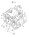
- a battery pack according to the present invention includes a plurality of battery cells 10, a holder case 20, a protection circuit module 30, a lead wire 50, and fixing ribs 21.
- the battery cells 10 are, for example, rechargeable cylindrical lithium ion batteries.
- the battery cells 10 according to an embodiment of the present invention are arranged in a five-series and two-parallel structure (5S*2P). That is, five sets of a battery cell group which has a set of two battery cells connected in parallel are connected by connection tabs.
- the connection tabs 40 are conductive devices made of copper etc. and electrically connect the battery cell groups.
- connection relationship of the battery cell groups is described in more detail with reference to FIG. 1A .
- two battery cells are connected in parallel.
- One end of each of the battery cells connected in parallel has a first pole and the other end has a second pole.
- the first poles of the battery cells are electrically connected to the protection circuit module by the connection tab 42 in FIG. 1A .
- the second poles of the battery cells are electrically connected with the first poles of the adjacent battery cells by the connection tab 40d in FIG. 1B .
- the battery cells having the second poles at the other end are electrically connected with the first poles of the next battery cells by the connection tab 40b.
- connection tab 42 the five-series and two-parallel structure (5S*2P) is exemplified, but the structure is not limited thereto and various connection structures may be used, as required.
- the holder case 20 of the present invention may be formed to cover at least a portion of the battery cells 10.
- the holder case 20 includes a cover 20a that covers the outer surfaces of the battery cells 10, and a first extender 20b and a second extender 20c disposed close to both ends of the battery cells 10, in the cover 20a.
- the first and second extenders 20b, 20c may extend to the spaces defined between adjacent battery cell groups. That is, the ends of the first and second extenders 20b, 20c may be formed in a shape matching with the circumference of the cylindrical battery cells 10, in which it is possible to prevent the battery cells from moving due to external shock.
- first and second extenders 20b, 20c have at least one or more fixing ribs 21 at both ends of the battery cells 10 to maintain and fix the position of the battery cells 10. Further, the fixing ribs 21 also have a function of guiding the lead wire 50 electrically connecting the battery cells 10 with the protection circuit module 30.
- the fixing ribs 21 are formed to contact the ends of the battery cells 10 and may be formed between the battery cells 10. Referring to FIG. 1A , the fixing rib 21 may be formed on the first extender 20b at the positions corresponding to the positions of the connection tabs 40a, 40b. Referring to FIG. 1B , the fixing rib 21 may be formed on the second extender 20c at the positions corresponding to the positions of the connection tabs 40c, 40d. That is, the first extender 20b extending from the cover 20a is positioned at the ends of the battery cells 10 and the second extender 20c is positioned at the other ends of the battery cells 10, such that the fixing ribs are alternately formed at both ends of the battery cells 10, thereby firmly fixing the battery cells 10 at their positions.
- FIG. 1C is a plan view schematically showing the top of the holder case 20, seen from above as described above. That is, as shown in FIG. 1C , the fixing ribs 21 of the present invention may be formed on the first extender 20b and the second extender 20c while being positioned on the first, second, third, and fourth connection tabs 40a, 40b, 40c, 40d. Further, the battery cells (10 in FIG. 1A ) fixed by welding with the first, second, third, and fourth connection tabs 40a, 40b, 40c, 40d are supported by the fixing ribs 21.
- the fixing ribs 21 disposed in a zigzag shape prevent the battery cells (10 in FIG. 1A ) from moving and also prevent the connection tabs 40 fixed to the battery cells from separating. That is, it is possible to improve durability of the battery pack against shock, drop and vibration.
- the battery cells are fixed in a zigzag shape in order not to be moved by the first, second, third, and fourth connection tabs 40a, 40b, 40c, 40d formed on the first extender 20b and the second extender 20c.
- the lead wire (not shown) passes through the first and second extenders 20b, 20c of the holder case, through the fixing rib 21 and a lead wire-through hole 23 formed in the fixing rib 21.
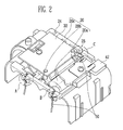
- guide grooves 24 are formed on the first and second extenders 20b, 20c such that the lead wire 50 can be guided without protruding outside. This is described in detail below.
- the fixing rib 21 is formed on the first extender 20b of the holder case (20, see FIG. 1 ) to support the connection tabs 40a, 40b, 40c, 40d positioned at the ends of the battery cells 10.
- the fixing rib 21 may be divided left and right with a predetermined gap therebetween and the gap may be the lead wire-through hole 23 for guiding the lead wire 50.
- protrusions 22 may be formed to protrude from both sides facing the lead wire-through hole of the fixing rib 21. The protrusions 22 function as locking members that prevent the lead wire passing through the lead wire-through hole 23 from being pulled out.
- the fixing fib 21 may be formed with the smallest area contacting the lead wire 50. That is, it is possible to minimize the contact area between the lead wire 50 and the fixing rib 21 by making the middle portion of the fixing rib 21 where the lead wire-through hole 23 is formed, smaller than the side of the fixing rib 21 which contacts the connection tab 40. This is because the coating of the lead wire 50 may peels off by the fixing rib 21, when shock is applied to the battery cells due to drop etc.
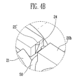
- the guide grooves 24 through which the lead wire 50 adjacent the fixing ribs 21 can pass may be further formed on the first extender and the second extender 20b, 20c. That is, the guide grooves 24 for guiding the lead wire 50 from the first extender and the second extender 20b, 20c of the holder case 20 when connecting the lead wire 50 passing through the lead wire-through hole 23 from the battery cells 10 to the protection circuit module 30 may be further formed. Protruding ribs, or protrusions, 25, 25' fixing or supporting the lead wire 50, which passes through, may be further formed inside the guide grooves 24.
- the protruding rib 25 shown in FIG. 4A may protrude at a constant thickness on both inner sides of the guide groove 24. Therefore, it is possible to the lead wire 50 inserted in the guide groove 24 from being separated outside.
- the protruding rib 25' shown in FIG. 4B may have a shape that decreases in thickness toward the inside of the guide groove 24. Therefore, the lead wire 50 press-fitted in the guide groove 24 can be seated inside the guide groove 25 without contacting the protruding rib 25'. That is, the lead wire 50 can move inside the protruding rib 25', but cannot be separated outside from the guide groove 24 by the protruding rib 25'. Further, though not shown, the protruding rib may protrude only at the inlet of the guide groove.
- a guide member 26 fixing the lead wire 50 not to be horizontally move may be further formed at the cover 20a of the holder case 20.
- the guide members 26, 26' described above are show in detail in FIGS. 5A and 5B .
- the guide member 26 that guides the lead wire 50 is further formed at the cover 20a (see FIG.1 ) of the holder case 20.
- the guide member 26 is formed in a T-shape to fix the lead wire 50 not to horizontally move.
- FIG. 5B is a perspective view showing a guide member different from that shown in FIG. 5A .
- the guide member 26' may be formed in an inverse L-shape with a hook 27 at the end. Therefore, similar to the guide member 26 of FIG. 5A , it can fix the lead wire 50 not to horizontally move while guiding the lead wire.
- the lead wire 50 is coated with a vinyl tube and connects the protection circuit module 30 with the battery cell 10.
- the lead wire 50 may be a monitoring lead wire that can measure cell balancing.
- the lead wire 50 may be connected with the connection tab 40 at one end and with the protection circuit module 30 at the other end.
- one end of the lead wire 50 may be connected with the connection tab 40 by soldering. It is possible to check whether current flows well to the battery cells 10, using the lead wire 50.
- the insulating sheet 60 is provided to prevent contact between the connection tab 40 (see FIG. 1 ) connected with the first and second poles of the battery cells 10 by welding and the external case 100 (see FIG. 7 ) which is the finish material. It is preferable that the insulating sheet 60 is made of a material having high thermal resistance in order to be prevented from being damaged by heat generated when current flows through the connection tab 40 or the lead wire 50.
- the protection module 30 may be installed at the cover 20a of the holder case 20. Electronic components are mounted on the protection circuit module 30, thereby implementing a protection circuit.
- the protection circuit module 30 is fixed to the holder case 20 by bolts, but may be fixed by other fasteners.
- an external case 100 may be further provided around the holder case 20 covering the battery cell 10.
- the external case 100 may be divided into a first case 100a and a second case 100b, which are fastened to each other.
- the first case 100a and the second case 100b may be fastened by a groove 101a and a protrusion 101b, which are formed at the cases, respectively.
- first case 100a and the second case 100b may be fixed by bolts or other means. Further, a groove and a protrusion for combination may be formed on the inner sides facing each other of the first case 100a and the second case 100b.
- the inner surface of the case 100a which contacts the first extender 20b of the holder case 20 may be formed in order not to interfere with the guide groove 24. That is, it is formed such that the lead wire 50 inserted in the guide groove 24 does not directly contact the first case 100a. Therefore, it is possible to prevent the coating of the lead wire 50 from peeling off.
- cylindrical battery cells are used in the embodiments of the present invention, it should be noted that other shapes of battery cells may be used.
Landscapes
- Chemical & Material Sciences (AREA)
- Chemical Kinetics & Catalysis (AREA)
- Electrochemistry (AREA)
- General Chemical & Material Sciences (AREA)
- Engineering & Computer Science (AREA)
- Microelectronics & Electronic Packaging (AREA)
- Manufacturing & Machinery (AREA)
- Battery Mounting, Suspending (AREA)
- Connection Of Batteries Or Terminals (AREA)
Applications Claiming Priority (2)
| Application Number | Priority Date | Filing Date | Title |
|---|---|---|---|
| US37456310P | 2010-08-17 | 2010-08-17 | |
| US13/042,816 US20120045665A1 (en) | 2010-08-17 | 2011-03-08 | Battery pack |
Publications (2)
| Publication Number | Publication Date |
|---|---|
| EP2421070A1 true EP2421070A1 (de) | 2012-02-22 |
| EP2421070B1 EP2421070B1 (de) | 2014-03-19 |
Family
ID=44503583
Family Applications (1)
| Application Number | Title | Priority Date | Filing Date |
|---|---|---|---|
| EP20110173199 Active EP2421070B1 (de) | 2010-08-17 | 2011-07-08 | Batteriepack |
Country Status (5)
| Country | Link |
|---|---|
| US (1) | US20120045665A1 (de) |
| EP (1) | EP2421070B1 (de) |
| JP (1) | JP5380501B2 (de) |
| KR (1) | KR101261722B1 (de) |
| CN (1) | CN102376901B (de) |
Cited By (2)
| Publication number | Priority date | Publication date | Assignee | Title |
|---|---|---|---|---|
| EP2830122A4 (de) * | 2012-03-21 | 2015-04-22 | Sanyo Electric Co | Zellenpaket sowie vorrichtung und verfahren zur herstellung des zellenpakets |
| EP3217452A1 (de) * | 2016-03-08 | 2017-09-13 | Samsung SDI Co., Ltd | Batteriepack |
Families Citing this family (24)
| Publication number | Priority date | Publication date | Assignee | Title |
|---|---|---|---|---|
| US20130052487A1 (en) * | 2011-08-31 | 2013-02-28 | Samsung Sdi Co., Ltd. | Battery pack |
| JP5847559B2 (ja) * | 2011-11-25 | 2016-01-27 | 三洋電機株式会社 | 電池パック |
| JP5823263B2 (ja) * | 2011-11-25 | 2015-11-25 | 三洋電機株式会社 | 電池パック |
| FR2990063B1 (fr) * | 2012-04-30 | 2016-12-09 | Batscap Sa | Dispositif pour le maintien d'ensemble de stockage d'energie electrique |
| KR101999404B1 (ko) * | 2013-01-28 | 2019-09-27 | 삼성에스디아이 주식회사 | 배터리 팩 |
| JP2014170635A (ja) * | 2013-03-01 | 2014-09-18 | Hitachi Koki Co Ltd | 電池パック及び電気機器 |
| WO2014185567A1 (ko) * | 2013-05-15 | 2014-11-20 | 주식회사 엘지화학 | 신규한 구조의 전지모듈 어셈블리 |
| JP6122150B2 (ja) * | 2013-05-15 | 2017-04-26 | エルジー・ケム・リミテッド | 新規な構造の電池モジュールアセンブリー |
| JP6092378B2 (ja) | 2013-05-23 | 2017-03-15 | 旭化成株式会社 | 熱可塑性樹脂組成物及びその成形品 |
| US20150037657A1 (en) * | 2013-07-31 | 2015-02-05 | Samsung Sdi Co., Ltd. | Battery pack |
| KR102073193B1 (ko) * | 2013-09-23 | 2020-02-04 | 삼성에스디아이 주식회사 | 배터리 팩 |
| KR102106447B1 (ko) * | 2013-12-09 | 2020-05-04 | 삼성에스디아이 주식회사 | 전지 모듈 |
| CN104752650B (zh) * | 2013-12-31 | 2017-05-03 | 比亚迪股份有限公司 | 动力电池模组 |
| KR102246772B1 (ko) | 2014-04-23 | 2021-04-30 | 삼성에스디아이 주식회사 | 배터리 팩 |
| CN104409670B (zh) * | 2014-12-05 | 2016-10-05 | 江苏天鹏电源有限公司 | 一种结构简单减震效果好的18v电池包 |
| KR102283959B1 (ko) * | 2015-03-05 | 2021-07-30 | 삼성에스디아이 주식회사 | 배터리 팩 |
| WO2017034543A1 (en) | 2015-08-24 | 2017-03-02 | Elitise Llc | Battery module housing assembly |
| JP6629592B2 (ja) | 2015-12-25 | 2020-01-15 | 株式会社マキタ | 電池パック |
| KR102711055B1 (ko) * | 2018-11-15 | 2024-09-27 | 주식회사 엘지에너지솔루션 | 배터리 모듈 및 이를 포함하는 배터리 팩 |
| JP2020170683A (ja) | 2019-04-05 | 2020-10-15 | 株式会社マキタ | バッテリパック |
| WO2022082394A1 (zh) | 2020-10-19 | 2022-04-28 | 江苏时代新能源科技有限公司 | 电池、用电装置、制备电池的方法和设备 |
| CN112072046B (zh) * | 2020-10-19 | 2022-12-27 | 江苏时代新能源科技有限公司 | 电池、用电装置、制备电池的方法和设备 |
| US20240106057A1 (en) * | 2021-02-25 | 2024-03-28 | Panasonic Energy Co., Ltd. | Battery pack |
| US20250192337A1 (en) * | 2022-03-18 | 2025-06-12 | Panasonic Energy Co.,Ltd. | Power supply device and lead holding structure |
Citations (6)
| Publication number | Priority date | Publication date | Assignee | Title |
|---|---|---|---|---|
| US5926659A (en) * | 1997-03-11 | 1999-07-20 | Nikon Corporation | Bracket for mounting a thermal-based electric current cutoff device within a piece of electronic equipment |
| JP2005317456A (ja) * | 2004-04-30 | 2005-11-10 | Sanyo Electric Co Ltd | パック電池 |
| EP1780825A1 (de) * | 2005-10-31 | 2007-05-02 | Black & Decker, Inc. | Akkupack und Innenbauelmentanordnung für ein schnurloses elektrisches Werkzeugsystem |
| WO2010079938A2 (ko) * | 2009-01-06 | 2010-07-15 | 주식회사 엘지화학 | 전지팩용 스페이서 및 이를 포함한 전지팩 |
| EP2282363A1 (de) * | 2009-07-01 | 2011-02-09 | Samsung SDI Co., Ltd. | Batteriepack mit Einzelzellen in einem Abstandshalter |
| EP2317585A2 (de) * | 2009-10-27 | 2011-05-04 | Samsung SDI Co., Ltd. | Batteriepack |
Family Cites Families (9)
| Publication number | Priority date | Publication date | Assignee | Title |
|---|---|---|---|---|
| US5143804A (en) * | 1991-05-08 | 1992-09-01 | Duracell Inc. | Battery assembly |
| JP2738503B2 (ja) * | 1994-05-27 | 1998-04-08 | 松下電器産業株式会社 | 保持具の係止構造 |
| US5704573A (en) * | 1995-08-28 | 1998-01-06 | Illinois Tool Works Inc. | Aperture held clip type fastener |
| JP2005197192A (ja) | 2004-01-09 | 2005-07-21 | Sanyo Electric Co Ltd | パック電池およびその組立方法 |
| JP4771679B2 (ja) | 2004-09-30 | 2011-09-14 | 三洋電機株式会社 | パック電池 |
| JP2007012302A (ja) * | 2005-06-28 | 2007-01-18 | Ryobi Ltd | 電動工具用電池パック |
| KR100930474B1 (ko) * | 2005-12-08 | 2009-12-09 | 주식회사 엘지화학 | 전지모듈 제조용 조립식 스페이서 |
| JP4916183B2 (ja) | 2006-02-20 | 2012-04-11 | 三洋電機株式会社 | パック電池 |
| WO2008021964A2 (en) * | 2006-08-09 | 2008-02-21 | Black & Decker Inc. | Battery pack and internal component arrangement within the battery pack for cordless power tool system |
-
2011
- 2011-03-08 US US13/042,816 patent/US20120045665A1/en not_active Abandoned
- 2011-05-18 CN CN201110133032.5A patent/CN102376901B/zh active Active
- 2011-07-08 EP EP20110173199 patent/EP2421070B1/de active Active
- 2011-07-15 KR KR1020110070265A patent/KR101261722B1/ko active Active
- 2011-08-15 JP JP2011177491A patent/JP5380501B2/ja active Active
Patent Citations (7)
| Publication number | Priority date | Publication date | Assignee | Title |
|---|---|---|---|---|
| US5926659A (en) * | 1997-03-11 | 1999-07-20 | Nikon Corporation | Bracket for mounting a thermal-based electric current cutoff device within a piece of electronic equipment |
| JP2005317456A (ja) * | 2004-04-30 | 2005-11-10 | Sanyo Electric Co Ltd | パック電池 |
| EP1780825A1 (de) * | 2005-10-31 | 2007-05-02 | Black & Decker, Inc. | Akkupack und Innenbauelmentanordnung für ein schnurloses elektrisches Werkzeugsystem |
| WO2010079938A2 (ko) * | 2009-01-06 | 2010-07-15 | 주식회사 엘지화학 | 전지팩용 스페이서 및 이를 포함한 전지팩 |
| EP2375471A2 (de) * | 2009-01-06 | 2011-10-12 | LG Chem, Ltd. | Distanzstück für batteriepackung und batteriepackung damit |
| EP2282363A1 (de) * | 2009-07-01 | 2011-02-09 | Samsung SDI Co., Ltd. | Batteriepack mit Einzelzellen in einem Abstandshalter |
| EP2317585A2 (de) * | 2009-10-27 | 2011-05-04 | Samsung SDI Co., Ltd. | Batteriepack |
Cited By (5)
| Publication number | Priority date | Publication date | Assignee | Title |
|---|---|---|---|---|
| EP2830122A4 (de) * | 2012-03-21 | 2015-04-22 | Sanyo Electric Co | Zellenpaket sowie vorrichtung und verfahren zur herstellung des zellenpakets |
| EP3217452A1 (de) * | 2016-03-08 | 2017-09-13 | Samsung SDI Co., Ltd | Batteriepack |
| US10454282B2 (en) | 2016-03-08 | 2019-10-22 | Samsung Sdi Co., Ltd. | Battery pack |
| US11081894B2 (en) | 2016-03-08 | 2021-08-03 | Samsung Sdi Co., Ltd. | Battery pack |
| EP4142014A3 (de) * | 2016-03-08 | 2023-08-09 | Samsung SDI Co., Ltd. | Batteriepack |
Also Published As
| Publication number | Publication date |
|---|---|
| EP2421070B1 (de) | 2014-03-19 |
| JP5380501B2 (ja) | 2014-01-08 |
| US20120045665A1 (en) | 2012-02-23 |
| JP2012043790A (ja) | 2012-03-01 |
| KR20120016992A (ko) | 2012-02-27 |
| CN102376901B (zh) | 2014-09-24 |
| KR101261722B1 (ko) | 2013-05-07 |
| CN102376901A (zh) | 2012-03-14 |
Similar Documents
| Publication | Publication Date | Title |
|---|---|---|
| EP2421070B1 (de) | Batteriepack | |
| EP2852992B1 (de) | Bolzenlose batteriezellenverbindung | |
| EP2538469B1 (de) | Batteriepack | |
| EP3005442B1 (de) | Batterieverbinderanordnung | |
| US9564661B2 (en) | Battery module and wiring module | |
| EP2791997B1 (de) | Batterieverbindersystem | |
| EP2416436B1 (de) | Spannungserkennungselement und batteriemodul damit | |
| JP6099211B2 (ja) | バッテリコネクタシステム | |
| EP2317585B1 (de) | Batteriepack | |
| EP2187465A1 (de) | Sekundärbatteriepack | |
| US20130052487A1 (en) | Battery pack | |
| KR101254903B1 (ko) | 퓨즈부를 구비하는 배터리 팩 | |
| WO2010147384A2 (ko) | 기구물체결방식의 유닛팩 조합형 셀 카트리지 | |
| JP2013054940A (ja) | 電池接続ユニット及び電源装置 | |
| KR102896641B1 (ko) | 배터리시스템 | |
| EP2424006B1 (de) | Batteriepack | |
| JP2013098032A (ja) | 電圧検知端子の接続構造 | |
| EP3490024B1 (de) | Batteriepack | |
| KR20260005129A (ko) | 배터리모듈 | |
| US20140003016A1 (en) | Battery monitoring system | |
| CN111630690A (zh) | 电池模块、包括该电池模块的电池组及其应用 | |
| CN119650915A (zh) | 电池模组 | |
| US11095003B2 (en) | Energy storage apparatus | |
| KR102285144B1 (ko) | 이차전지 |
Legal Events
| Date | Code | Title | Description |
|---|---|---|---|
| AK | Designated contracting states |
Kind code of ref document: A1 Designated state(s): AL AT BE BG CH CY CZ DE DK EE ES FI FR GB GR HR HU IE IS IT LI LT LU LV MC MK MT NL NO PL PT RO RS SE SI SK SM TR |
|
| AX | Request for extension of the european patent |
Extension state: BA ME |
|
| PUAI | Public reference made under article 153(3) epc to a published international application that has entered the european phase |
Free format text: ORIGINAL CODE: 0009012 |
|
| 17P | Request for examination filed |
Effective date: 20120321 |
|
| 17Q | First examination report despatched |
Effective date: 20130404 |
|
| GRAP | Despatch of communication of intention to grant a patent |
Free format text: ORIGINAL CODE: EPIDOSNIGR1 |
|
| RIC1 | Information provided on ipc code assigned before grant |
Ipc: H01M 10/50 20060101ALN20130819BHEP Ipc: H01M 2/10 20060101AFI20130819BHEP Ipc: H01M 10/42 20060101ALN20130819BHEP Ipc: H01M 2/20 20060101ALI20130819BHEP |
|
| INTG | Intention to grant announced |
Effective date: 20130912 |
|
| GRAS | Grant fee paid |
Free format text: ORIGINAL CODE: EPIDOSNIGR3 |
|
| GRAA | (expected) grant |
Free format text: ORIGINAL CODE: 0009210 |
|
| AK | Designated contracting states |
Kind code of ref document: B1 Designated state(s): AL AT BE BG CH CY CZ DE DK EE ES FI FR GB GR HR HU IE IS IT LI LT LU LV MC MK MT NL NO PL PT RO RS SE SI SK SM TR |
|
| REG | Reference to a national code |
Ref country code: GB Ref legal event code: FG4D |
|
| RIC1 | Information provided on ipc code assigned before grant |
Ipc: H01M 10/42 20060101ALN20140210BHEP Ipc: H01M 2/20 20060101ALI20140210BHEP Ipc: H01M 2/10 20060101AFI20140210BHEP Ipc: H01M 10/658 20140101ALN20140210BHEP |
|
| REG | Reference to a national code |
Ref country code: CH Ref legal event code: EP |
|
| REG | Reference to a national code |
Ref country code: IE Ref legal event code: FG4D |
|
| REG | Reference to a national code |
Ref country code: AT Ref legal event code: REF Ref document number: 658169 Country of ref document: AT Kind code of ref document: T Effective date: 20140415 |
|
| REG | Reference to a national code |
Ref country code: DE Ref legal event code: R096 Ref document number: 602011005416 Country of ref document: DE Effective date: 20140508 |
|
| PG25 | Lapsed in a contracting state [announced via postgrant information from national office to epo] |
Ref country code: LT Free format text: LAPSE BECAUSE OF FAILURE TO SUBMIT A TRANSLATION OF THE DESCRIPTION OR TO PAY THE FEE WITHIN THE PRESCRIBED TIME-LIMIT Effective date: 20140319 Ref country code: NO Free format text: LAPSE BECAUSE OF FAILURE TO SUBMIT A TRANSLATION OF THE DESCRIPTION OR TO PAY THE FEE WITHIN THE PRESCRIBED TIME-LIMIT Effective date: 20140619 |
|
| REG | Reference to a national code |
Ref country code: NL Ref legal event code: VDEP Effective date: 20140319 |
|
| REG | Reference to a national code |
Ref country code: AT Ref legal event code: MK05 Ref document number: 658169 Country of ref document: AT Kind code of ref document: T Effective date: 20140319 |
|
| REG | Reference to a national code |
Ref country code: LT Ref legal event code: MG4D |
|
| PG25 | Lapsed in a contracting state [announced via postgrant information from national office to epo] |
Ref country code: FI Free format text: LAPSE BECAUSE OF FAILURE TO SUBMIT A TRANSLATION OF THE DESCRIPTION OR TO PAY THE FEE WITHIN THE PRESCRIBED TIME-LIMIT Effective date: 20140319 Ref country code: SE Free format text: LAPSE BECAUSE OF FAILURE TO SUBMIT A TRANSLATION OF THE DESCRIPTION OR TO PAY THE FEE WITHIN THE PRESCRIBED TIME-LIMIT Effective date: 20140319 Ref country code: CY Free format text: LAPSE BECAUSE OF FAILURE TO SUBMIT A TRANSLATION OF THE DESCRIPTION OR TO PAY THE FEE WITHIN THE PRESCRIBED TIME-LIMIT Effective date: 20140319 |
|
| PG25 | Lapsed in a contracting state [announced via postgrant information from national office to epo] |
Ref country code: HR Free format text: LAPSE BECAUSE OF FAILURE TO SUBMIT A TRANSLATION OF THE DESCRIPTION OR TO PAY THE FEE WITHIN THE PRESCRIBED TIME-LIMIT Effective date: 20140319 Ref country code: LV Free format text: LAPSE BECAUSE OF FAILURE TO SUBMIT A TRANSLATION OF THE DESCRIPTION OR TO PAY THE FEE WITHIN THE PRESCRIBED TIME-LIMIT Effective date: 20140319 Ref country code: RS Free format text: LAPSE BECAUSE OF FAILURE TO SUBMIT A TRANSLATION OF THE DESCRIPTION OR TO PAY THE FEE WITHIN THE PRESCRIBED TIME-LIMIT Effective date: 20140319 |
|
| PG25 | Lapsed in a contracting state [announced via postgrant information from national office to epo] |
Ref country code: CZ Free format text: LAPSE BECAUSE OF FAILURE TO SUBMIT A TRANSLATION OF THE DESCRIPTION OR TO PAY THE FEE WITHIN THE PRESCRIBED TIME-LIMIT Effective date: 20140319 Ref country code: NL Free format text: LAPSE BECAUSE OF FAILURE TO SUBMIT A TRANSLATION OF THE DESCRIPTION OR TO PAY THE FEE WITHIN THE PRESCRIBED TIME-LIMIT Effective date: 20140319 Ref country code: IS Free format text: LAPSE BECAUSE OF FAILURE TO SUBMIT A TRANSLATION OF THE DESCRIPTION OR TO PAY THE FEE WITHIN THE PRESCRIBED TIME-LIMIT Effective date: 20140719 Ref country code: RO Free format text: LAPSE BECAUSE OF FAILURE TO SUBMIT A TRANSLATION OF THE DESCRIPTION OR TO PAY THE FEE WITHIN THE PRESCRIBED TIME-LIMIT Effective date: 20140319 Ref country code: BE Free format text: LAPSE BECAUSE OF FAILURE TO SUBMIT A TRANSLATION OF THE DESCRIPTION OR TO PAY THE FEE WITHIN THE PRESCRIBED TIME-LIMIT Effective date: 20140319 Ref country code: BG Free format text: LAPSE BECAUSE OF FAILURE TO SUBMIT A TRANSLATION OF THE DESCRIPTION OR TO PAY THE FEE WITHIN THE PRESCRIBED TIME-LIMIT Effective date: 20140619 Ref country code: EE Free format text: LAPSE BECAUSE OF FAILURE TO SUBMIT A TRANSLATION OF THE DESCRIPTION OR TO PAY THE FEE WITHIN THE PRESCRIBED TIME-LIMIT Effective date: 20140319 |
|
| PG25 | Lapsed in a contracting state [announced via postgrant information from national office to epo] |
Ref country code: ES Free format text: LAPSE BECAUSE OF FAILURE TO SUBMIT A TRANSLATION OF THE DESCRIPTION OR TO PAY THE FEE WITHIN THE PRESCRIBED TIME-LIMIT Effective date: 20140319 Ref country code: SK Free format text: LAPSE BECAUSE OF FAILURE TO SUBMIT A TRANSLATION OF THE DESCRIPTION OR TO PAY THE FEE WITHIN THE PRESCRIBED TIME-LIMIT Effective date: 20140319 Ref country code: PL Free format text: LAPSE BECAUSE OF FAILURE TO SUBMIT A TRANSLATION OF THE DESCRIPTION OR TO PAY THE FEE WITHIN THE PRESCRIBED TIME-LIMIT Effective date: 20140319 Ref country code: AT Free format text: LAPSE BECAUSE OF FAILURE TO SUBMIT A TRANSLATION OF THE DESCRIPTION OR TO PAY THE FEE WITHIN THE PRESCRIBED TIME-LIMIT Effective date: 20140319 |
|
| REG | Reference to a national code |
Ref country code: DE Ref legal event code: R097 Ref document number: 602011005416 Country of ref document: DE |
|
| PG25 | Lapsed in a contracting state [announced via postgrant information from national office to epo] |
Ref country code: PT Free format text: LAPSE BECAUSE OF FAILURE TO SUBMIT A TRANSLATION OF THE DESCRIPTION OR TO PAY THE FEE WITHIN THE PRESCRIBED TIME-LIMIT Effective date: 20140721 |
|
| PLBE | No opposition filed within time limit |
Free format text: ORIGINAL CODE: 0009261 |
|
| STAA | Information on the status of an ep patent application or granted ep patent |
Free format text: STATUS: NO OPPOSITION FILED WITHIN TIME LIMIT |
|
| PG25 | Lapsed in a contracting state [announced via postgrant information from national office to epo] |
Ref country code: DK Free format text: LAPSE BECAUSE OF FAILURE TO SUBMIT A TRANSLATION OF THE DESCRIPTION OR TO PAY THE FEE WITHIN THE PRESCRIBED TIME-LIMIT Effective date: 20140319 |
|
| 26N | No opposition filed |
Effective date: 20141222 |
|
| PG25 | Lapsed in a contracting state [announced via postgrant information from national office to epo] |
Ref country code: LU Free format text: LAPSE BECAUSE OF FAILURE TO SUBMIT A TRANSLATION OF THE DESCRIPTION OR TO PAY THE FEE WITHIN THE PRESCRIBED TIME-LIMIT Effective date: 20140708 |
|
| REG | Reference to a national code |
Ref country code: CH Ref legal event code: PL |
|
| PG25 | Lapsed in a contracting state [announced via postgrant information from national office to epo] |
Ref country code: IT Free format text: LAPSE BECAUSE OF FAILURE TO SUBMIT A TRANSLATION OF THE DESCRIPTION OR TO PAY THE FEE WITHIN THE PRESCRIBED TIME-LIMIT Effective date: 20140319 |
|
| REG | Reference to a national code |
Ref country code: DE Ref legal event code: R097 Ref document number: 602011005416 Country of ref document: DE Effective date: 20141222 |
|
| REG | Reference to a national code |
Ref country code: IE Ref legal event code: MM4A |
|
| PG25 | Lapsed in a contracting state [announced via postgrant information from national office to epo] |
Ref country code: CH Free format text: LAPSE BECAUSE OF NON-PAYMENT OF DUE FEES Effective date: 20140731 Ref country code: LI Free format text: LAPSE BECAUSE OF NON-PAYMENT OF DUE FEES Effective date: 20140731 |
|
| PG25 | Lapsed in a contracting state [announced via postgrant information from national office to epo] |
Ref country code: SI Free format text: LAPSE BECAUSE OF FAILURE TO SUBMIT A TRANSLATION OF THE DESCRIPTION OR TO PAY THE FEE WITHIN THE PRESCRIBED TIME-LIMIT Effective date: 20140319 |
|
| PG25 | Lapsed in a contracting state [announced via postgrant information from national office to epo] |
Ref country code: IE Free format text: LAPSE BECAUSE OF NON-PAYMENT OF DUE FEES Effective date: 20140708 |
|
| PG25 | Lapsed in a contracting state [announced via postgrant information from national office to epo] |
Ref country code: MC Free format text: LAPSE BECAUSE OF FAILURE TO SUBMIT A TRANSLATION OF THE DESCRIPTION OR TO PAY THE FEE WITHIN THE PRESCRIBED TIME-LIMIT Effective date: 20140319 Ref country code: SM Free format text: LAPSE BECAUSE OF FAILURE TO SUBMIT A TRANSLATION OF THE DESCRIPTION OR TO PAY THE FEE WITHIN THE PRESCRIBED TIME-LIMIT Effective date: 20140319 |
|
| REG | Reference to a national code |
Ref country code: FR Ref legal event code: PLFP Year of fee payment: 6 |
|
| PG25 | Lapsed in a contracting state [announced via postgrant information from national office to epo] |
Ref country code: MT Free format text: LAPSE BECAUSE OF FAILURE TO SUBMIT A TRANSLATION OF THE DESCRIPTION OR TO PAY THE FEE WITHIN THE PRESCRIBED TIME-LIMIT Effective date: 20140319 Ref country code: GR Free format text: LAPSE BECAUSE OF FAILURE TO SUBMIT A TRANSLATION OF THE DESCRIPTION OR TO PAY THE FEE WITHIN THE PRESCRIBED TIME-LIMIT Effective date: 20140620 |
|
| PG25 | Lapsed in a contracting state [announced via postgrant information from national office to epo] |
Ref country code: TR Free format text: LAPSE BECAUSE OF FAILURE TO SUBMIT A TRANSLATION OF THE DESCRIPTION OR TO PAY THE FEE WITHIN THE PRESCRIBED TIME-LIMIT Effective date: 20140319 Ref country code: HU Free format text: LAPSE BECAUSE OF FAILURE TO SUBMIT A TRANSLATION OF THE DESCRIPTION OR TO PAY THE FEE WITHIN THE PRESCRIBED TIME-LIMIT; INVALID AB INITIO Effective date: 20110708 |
|
| REG | Reference to a national code |
Ref country code: FR Ref legal event code: PLFP Year of fee payment: 7 |
|
| PG25 | Lapsed in a contracting state [announced via postgrant information from national office to epo] |
Ref country code: MK Free format text: LAPSE BECAUSE OF FAILURE TO SUBMIT A TRANSLATION OF THE DESCRIPTION OR TO PAY THE FEE WITHIN THE PRESCRIBED TIME-LIMIT Effective date: 20140319 |
|
| REG | Reference to a national code |
Ref country code: FR Ref legal event code: PLFP Year of fee payment: 8 |
|
| PG25 | Lapsed in a contracting state [announced via postgrant information from national office to epo] |
Ref country code: AL Free format text: LAPSE BECAUSE OF FAILURE TO SUBMIT A TRANSLATION OF THE DESCRIPTION OR TO PAY THE FEE WITHIN THE PRESCRIBED TIME-LIMIT Effective date: 20140319 |
|
| REG | Reference to a national code |
Ref country code: DE Ref legal event code: R079 Ref document number: 602011005416 Country of ref document: DE Free format text: PREVIOUS MAIN CLASS: H01M0002100000 Ipc: H01M0050200000 |
|
| P01 | Opt-out of the competence of the unified patent court (upc) registered |
Effective date: 20230528 |
|
| PGFP | Annual fee paid to national office [announced via postgrant information from national office to epo] |
Ref country code: GB Payment date: 20250626 Year of fee payment: 15 |
|
| PGFP | Annual fee paid to national office [announced via postgrant information from national office to epo] |
Ref country code: FR Payment date: 20250623 Year of fee payment: 15 |
|
| PGFP | Annual fee paid to national office [announced via postgrant information from national office to epo] |
Ref country code: DE Payment date: 20250624 Year of fee payment: 15 |