EP2421074B1 - Electrodes de type roulé et ensemble formant électrode doté de celui-ci - Google Patents
Electrodes de type roulé et ensemble formant électrode doté de celui-ci Download PDFInfo
- Publication number
- EP2421074B1 EP2421074B1 EP11178172.0A EP11178172A EP2421074B1 EP 2421074 B1 EP2421074 B1 EP 2421074B1 EP 11178172 A EP11178172 A EP 11178172A EP 2421074 B1 EP2421074 B1 EP 2421074B1
- Authority
- EP
- European Patent Office
- Prior art keywords
- current collector
- auxiliary current
- mandrel
- plate
- negative
- Prior art date
- Legal status (The legal status is an assumption and is not a legal conclusion. Google has not performed a legal analysis and makes no representation as to the accuracy of the status listed.)
- Active
Links
Images




Classifications
-
- H—ELECTRICITY
- H01—ELECTRIC ELEMENTS
- H01M—PROCESSES OR MEANS, e.g. BATTERIES, FOR THE DIRECT CONVERSION OF CHEMICAL ENERGY INTO ELECTRICAL ENERGY
- H01M10/00—Secondary cells; Manufacture thereof
- H01M10/04—Construction or manufacture in general
- H01M10/0431—Cells with wound or folded electrodes
-
- H—ELECTRICITY
- H01—ELECTRIC ELEMENTS
- H01M—PROCESSES OR MEANS, e.g. BATTERIES, FOR THE DIRECT CONVERSION OF CHEMICAL ENERGY INTO ELECTRICAL ENERGY
- H01M10/00—Secondary cells; Manufacture thereof
- H01M10/05—Accumulators with non-aqueous electrolyte
- H01M10/058—Construction or manufacture
- H01M10/0587—Construction or manufacture of accumulators having only wound construction elements, i.e. wound positive electrodes, wound negative electrodes and wound separators
-
- H—ELECTRICITY
- H01—ELECTRIC ELEMENTS
- H01M—PROCESSES OR MEANS, e.g. BATTERIES, FOR THE DIRECT CONVERSION OF CHEMICAL ENERGY INTO ELECTRICAL ENERGY
- H01M4/00—Electrodes
- H01M4/02—Electrodes composed of, or comprising, active material
- H01M4/64—Carriers or collectors
- H01M4/66—Selection of materials
- H01M4/661—Metal or alloys, e.g. alloy coatings
-
- H—ELECTRICITY
- H01—ELECTRIC ELEMENTS
- H01M—PROCESSES OR MEANS, e.g. BATTERIES, FOR THE DIRECT CONVERSION OF CHEMICAL ENERGY INTO ELECTRICAL ENERGY
- H01M4/00—Electrodes
- H01M4/02—Electrodes composed of, or comprising, active material
- H01M4/64—Carriers or collectors
- H01M4/66—Selection of materials
- H01M4/663—Selection of materials containing carbon or carbonaceous materials as conductive part, e.g. graphite, carbon fibres
-
- H—ELECTRICITY
- H01—ELECTRIC ELEMENTS
- H01M—PROCESSES OR MEANS, e.g. BATTERIES, FOR THE DIRECT CONVERSION OF CHEMICAL ENERGY INTO ELECTRICAL ENERGY
- H01M50/00—Constructional details or processes of manufacture of the non-active parts of electrochemical cells other than fuel cells, e.g. hybrid cells
- H01M50/50—Current conducting connections for cells or batteries
- H01M50/531—Electrode connections inside a battery casing
- H01M50/538—Connection of several leads or tabs of wound or folded electrode stacks
-
- Y—GENERAL TAGGING OF NEW TECHNOLOGICAL DEVELOPMENTS; GENERAL TAGGING OF CROSS-SECTIONAL TECHNOLOGIES SPANNING OVER SEVERAL SECTIONS OF THE IPC; TECHNICAL SUBJECTS COVERED BY FORMER USPC CROSS-REFERENCE ART COLLECTIONS [XRACs] AND DIGESTS
- Y02—TECHNOLOGIES OR APPLICATIONS FOR MITIGATION OR ADAPTATION AGAINST CLIMATE CHANGE
- Y02E—REDUCTION OF GREENHOUSE GAS [GHG] EMISSIONS, RELATED TO ENERGY GENERATION, TRANSMISSION OR DISTRIBUTION
- Y02E60/00—Enabling technologies; Technologies with a potential or indirect contribution to GHG emissions mitigation
- Y02E60/10—Energy storage using batteries
-
- Y—GENERAL TAGGING OF NEW TECHNOLOGICAL DEVELOPMENTS; GENERAL TAGGING OF CROSS-SECTIONAL TECHNOLOGIES SPANNING OVER SEVERAL SECTIONS OF THE IPC; TECHNICAL SUBJECTS COVERED BY FORMER USPC CROSS-REFERENCE ART COLLECTIONS [XRACs] AND DIGESTS
- Y02—TECHNOLOGIES OR APPLICATIONS FOR MITIGATION OR ADAPTATION AGAINST CLIMATE CHANGE
- Y02P—CLIMATE CHANGE MITIGATION TECHNOLOGIES IN THE PRODUCTION OR PROCESSING OF GOODS
- Y02P70/00—Climate change mitigation technologies in the production process for final industrial or consumer products
- Y02P70/50—Manufacturing or production processes characterised by the final manufactured product
Definitions
- the present invention relates to a jelly roll and an electrode assembly having the same, and more particularly, to a jelly roll which facilitates an assembly process and has structural stability and an electrode assembly having the jelly roll.
- a secondary battery is a chemical cell which may be repeatedly charged and discharged via reversible conversion between chemical energy and electrical energy. Recently, since telecommunication equipment is widely used and automotive batteries require a higher capacity and a higher output emerge, lithium secondary batteries having a higher voltage and a higher capacity density are required.
- Capacity may be defined by "specific capacity” (a weight characteristic) and “capacity density” (a volume characteristic).
- a high quality battery generally has both a high specific capacity and a high capacity density and contains high-density materials.
- a lithium-ion secondary battery mainly includes a positive active material, a negative active material, an electrolyte, and a separator.
- the positive active material generally includes LiCO 2
- the negative active material generally includes carbon materials, such as graphite, occluding and emitting lithium as ions.
- DE 10 2007 000428 discloses a jelly roll comprising a separator, first and second electrode plates with coated and uncoated areas, wherein the uncoated areas are exposed to the edges of the separator, respectively.
- the jelly roll is wound around a mandrel, comprising an insulation layer that insulates and spaces apart a first auxiliary current collector from the second auxiliary current collector, insulating the auxiliary current collectors from an exterior.
- JP 2010 146872 discloses a jelly roll comprising an anode plate with coated and uncoated regions, a cathode plate with coated and uncoated regions and a separator inbetween. The uncoated regions extend to the respective edges of the separator.
- a mandrel is made of insulating material and comprises auxiliary current collectors on each end and which are insulated from the exterior by the mandrel.
- An aspect of the present invention sets out to provide a jelly roll which can be easily made by a winding process.
- Another aspect of the present invention sets out to provide an electrode assembly including a terminal and a current collector and eliminating unnecessary space within the electrode assembly.
- the size of such electrode assembly may be advantageously minimized.
- Still another aspect of the present invention provides an electrode assembly in which a jelly roll is securely settled during fabrication, and is thus physically stable after the completion of manufacture in order to minimize deformation occurring during charging and discharging and to have a strong structure against external impact.
- a jelly roll may include a first auxiliary current collector, a second auxiliary current collector, a mandrel insulating layer, and an electrode plate.
- the first auxiliary current collector and the second auxiliary current collector are spaced a part from each other and each have a mandrel protrusion on a respective opposite end portion.
- the mandrel insulating layer insulates the auxiliary current collectors from each other and insulates the auxiliary current collectors from an exterior.
- the electrode plate is formed by layering a separator, a first electrode plate, a separator and a second electrode plate in sequence and the electrode plate may be wound on an outer surface of the mandrel insulating layer, wherein the first auxiliary current collector and the second auxiliary current collector are wound with the electrode plate so that only the mandrel protrusions are exposed.
- the first electrode plate includes a positive active material layer to which a positive active material is applied and a positive non-applied part to which the positive active material is not applied
- the second electrode plate includes a negative active material layer to which a negative active material is applied and a negative non-applied part to which the negative active material is not applied.
- the electrode plates may be deposited with the positive non-applied part being exposed to one edge of the separator and the negative non-applied part being exposed to another opposite edge of the separator.
- the first auxiliary current collector may include an alloy of at least one of aluminum, nickel, titanium and plastic carbon.
- the second auxiliary current collector may include an alloy of at least one of copper, stainless steel, aluminum and nickel.
- Two or more mandrel protrusions may be formed on each auxiliary current collector.
- an electrode assembly may include a first auxiliary current collector, a second auxiliary current collector, a mandrel insulating layer, an electrode plate, a first main current collector, and a second main current collector.
- the first auxiliary current collector and the second auxiliary current collector are spaced apart from each other and each have a mandrel protrusion on a respective opposite end portion.
- the mandrel insulating layer insulates the auxiliary current collectors from each other and insulates the auxiliary current collectors from an outside.
- the electrode plate is formed by layering a separator, a first electrode plate, a separator and a second electrode plate in sequence and the electrode plate is wound on an outer surface of the mandrel insulating layer.
- Each of the first and second main current collectors includes a side plate in which a mandrel protrusion accommodating hole to accommodate the mandrel protrusion is formed and a cap plate extending from an edge of the side plate in a perpendicular direction.
- An electrode terminal is formed on the cap plate.
- a current collector insulating part connects the cap plate of the first main current collector with the cap plate of the second main current collector.
- first main current collector, the second main current collector, and the current collector insulating part may be simultaneously and integrally formed as a single body.
- the first electrode plate may include a positive active material layer to which a positive active material is applied and a positive non-applied part to which the positive active material is not applied
- the second electrode plate comprises a negative active material layer to which a negative active material is applied and a negative non-applied part to which the negative active material is not applied.
- the electrode plates are deposited with the positive non-applied part being exposed to one edge of the separator and the negative non-applied part being exposed to another opposite edge of the separator.
- an adhesive inlet injecting an adhesive may be formed in the side plate of the first main current collector and in the side plate of the second main current collector.
- an adhesive injected into the adhesive inlet may be electrically conductive. Also, the adhesive may adhere the first main current collector to the positive non-applied part and may adhere the second main current collector to the negative non-applied part.
- the adhesive may adhere the first auxiliary current collector to the positive non-applied part and may adhere the second auxiliary current collector to the negative non-applied part.
- two or more mandrel protrusions may be formed on each auxiliary current collector.
- At least one adhesive inlet may be provided between the mandrel protrusions.
- a conductive adhesive may be injected into the adhesive inlet.
- mandrel protrusion accommodating hole and the mandrel protrusions inserted into the mandrel protrusion accommodating hole may be welded together.
- an auxiliary current collector functioning as a mandrel in a winding process is provided to facilitate the winding process.
- an auxiliary current collector is securely fixed to a main current collector, so that deformation of a secondary battery is minimized in charging and discharging and sufficient strength is maintained when dropped.
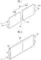
- FIG. 1 is an oblique view illustrating an auxiliary current collector constructed as an embodiment of the invention.
- the auxiliary current collector 110 includes a first auxiliary current collector 110a and a second auxiliary current collector 110b.
- the first auxiliary current collector 110a acts as a positive auxiliary current collector
- the second auxiliary current collector 110b may act as a negative auxiliary current collector.
- the first auxiliary current collector 110a may act as a negative auxiliary current collector
- the second auxiliary current collector 110b may act as a positive auxiliary current collector.
- the first auxiliary current collector 110a is hereafter referred to as a positive auxiliary current collector
- the second auxiliary current collector 110b is hereafter referred to as a negative auxiliary current collector.
- the positive auxiliary current collector 110a and the negative auxiliary current collector 110b are each formed in a rectangular plate shape.
- the positive auxiliary current collector 110a and the negative auxiliary current collector 110b are disposed spaced apart from each other.
- one side Sa1 of the positive auxiliary current collector 110a is disposed to face toward one side Sb1 of the negative auxiliary current collector 110b, and the positive auxiliary current collector 110a is aligned with the negative auxiliary current collector 110b in a same plane.
- a mandrel protrusion 111 is formed on an end portion Sa2 of the positive auxiliary current collector 110a opposite to the negative auxiliary current collector 110b, and another mandrel protrusion 111 is formed on an end portion Sb2 of the negative auxiliary current collector 110b disposed opposite to the positive auxiliary current collector 110a.
- the mandrel protrusion 111 formed on the positive auxiliary current collector 110a protrudes away from the negative auxiliary current collector 110b; the mandrel protrusion 111 formed on the negative auxiliary current collector 110b protrudes away from the positive auxiliary current collector 110a.
- the mandrel protrusions 111 function as a mandrel when an electrode plate 150 is wound into a jelly roll (see FIG. 4A ).
- a pair of mandrel protrusions 111 may be formed on one side of each of auxiliary current collectors. In such a case, two or more mandrel protrusions 111 are formed on each single auxiliary current collector so that the mandrel protrusions 111 may be settled securely in a winder 300 (see FIG. 4A ).
- the positive auxiliary current collector 110a may include aluminum (A1) or an aluminum alloy, and the negative auxiliary current collector 110b may include copper (Cu) or a copper alloy.
- FIG. 2 is an oblique view illustrating the auxiliary current collector of Figure 1 and a mandrel insulating layer assembled together in accordance with the invention.
- the mandrel insulating layer 120 includes an insulating material and may be formed via molding in order to encompass an outside of the auxiliary current collectors 110.
- the mandrel insulating layer 120 insulates the positive auxiliary current collector 110a and the negative auxiliary current collector 110b from each other, and insulates the auxiliary current collectors 110 from an electrode plate 150 which is to be wound around the auxiliary current collectors 110.
- the mandrel insulating layer 120 is formed from electrical insulating material.
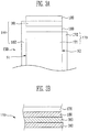
- FIG. 3A is an exploded partial plan view illustrating the electrode plate 150
- FIG. 3B is a partial cross-sectional view illustrating the electrode plate 150
- the electrode plate 150 includes a first electrode plate 160, a second electrode plate 170, and a separator 180.
- the first electrode plate 160 is a positive electrode plate
- the second electrode plate 170 may be a negative electrode plate.
- the first electrode plate 160 may be a negative electrode plate
- the second electrode plate 170 is a positive electrode plate.
- the first electrode plate 160 is hereafter denoted as positive
- a second electrode plate 170 is hereafter denoted as negative.
- the positive plate 160 includes a positive active material layer 161 in which a positive active material is applied to both surfaces or one surface of a positive current collector and a positive non-applied part 162 to which the positive active material is not applied.
- the positive current collector generally uses material having a high conductivity and a high chemical stability.
- the positive current collector may include aluminum, nickel, titanium, plastic carbon, and the like.
- the positive active material layer 161 may be formed by applying slurry to the positive current collector, with the slurry being prepared by mixing a positive active material, a conductive material, and a binder with a solvent.
- the negative plate 170 includes a negative active material layer 171 in which a negative active material is applied to both surfaces or one surface of a negative current collector and a negative non-applied part 172 to which the negative active material is not applied.
- the negative plate 170 may include conductive metal, for example, copper, stainless steel, aluminum, nickel, and the like.
- the negative active material layer 171 may be formed by applying slurry to a negative current collector, with the slurry being prepared by mixing a negative active material and a binder to improve coherence of the negative active material with a solvent.
- the separator 180 is interposed between the positive active material layer 161 and the negative active material layer 171.
- the separator 180 functions as a passage for ions and prevents a direct contact between the positive plate 160 and the negative plate 170.
- the separator 180 is formed of an insulating thin film having a high ion permeability and a high mechanical strength.
- the separator 180 may be formed of an electrical insulating thin film.
- the separator 180 may use a porous film including polyethylene, polypropylene or polyvinylidene fluoride, or felt.
- FIG. 3B shows a cross-sectional view of the structure of the electrode plate 150.
- the electrode plate 150 is formed by layering the separator 180, the positive plate 160, the separator 180, and the negative plate 170 in order.
- the positive plate 160, the separator 180, the negative plate 170, and the separator 180 may be layered as shown because the above layered structure is repeated in winding.
- the positive plate 160 includes the positive active material layer 161 and the positive non-applied part 162 and the negative plate 170 includes the negative active material layer 171 and the negative non-applied part 172.
- the positive plate 160 is deposited on the separator 180, the positive non-applied part 162 is exposed to one side (or edge) S1 of the separator 180.
- the negative plate 170 is deposited on the separator 180, the negative non-applied part 172 is exposed to another side (or edge) S2 of the separator 180.
- the electrode plate 150 is wound, as shown in FIG.
- the positive non-applied part 162 is exposed to one side S1 of the separator 180, and the negative non-applied part 172 is exposed to the other side S2 of the separator 180.
- the positive non-applied part 162 is not covered by the separator 180 and is exposed at one edge S1 of the separator 180; the negative non-applied part 172 is not covered by the separator 180 and is exposed at an opposite edge S2 of the separator 180.
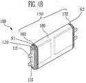
- FIG. 4A is an oblique view illustrating a process of winding the jelly roll 100
- FIG. 4B is an oblique view the wound jelly roll 100.
- the winder 300 is a device for winding the electrode plate 150 on an outside of the mandrel insulating layer 120.
- the winder 300 includes a mandrel protrusion fixing unit 310 to accommodate and settle the mandrel protrusions 111 on a rotation shaft of a sub-motor and performs a winding process.
- the alignment of the positive plate 160, the separator 180, and the negative plate 170 is important, and thus winding is uniformly performed.
- the auxiliary current collectors 110 may be wound in a situation where only the mandrel protrusions are exposed to the exterior of the jelly roll in view of risk of a short circuit.
- FIG. 4C is an oblique view illustrating a reference embodiment.
- a stack 100a includes an auxiliary current collector 110, a mandrel insulating layer 120, and a stacked type electrode plate 150a.
- FIG. 4C shows a stacked type electrode plate 150a which is different from the jelly roll type electrode plate 150 of FIG. 4B .
- the stacked type electrode plate 150a is formed by stacking layers 1000.
- the positive non-applied part 162a is not covered by the separator 180a and is exposed at one edge of the separator 180a; the negative non-applied part 172a is not covered by the separator 180a and is exposed at an opposite edge of the separator 180a.
- FIG. 5 shows an oblique view of the current collector 200 including a mains current collector 210.
- the main current collector 210 collectively includes a positive side plate 210a, a positive cap plate 210c, a negative side plate 210b, and a negative cap plate 210d.
- the main current collector 210 may be formed by bending one plate twice at a right angle.
- two plates i.e., the side plates 210a and 210b, face towards each other and are disposed opposite to each other.
- Two side plates 210a and 210b are physically connected by the cap plates 210c and 210d, and the two side plates 210a and 210b are electrically insulated from each other by a current collector insulating part 230.
- the current collector insulating part 230 is provided between the two cap plates 210c and 210d in order to electrically insulate the cap plate 210c from the cap plate 210d.
- the side plates 210a and 210b, the cap plates 210c and 210d, and the current collector insulating part 230 may be simultaneously and integrally formed as a single body via double injection molding, or may be manufactured separately and combined via soldering or welding.
- a pair of mandrel protrusion accommodating holes 212 is formed in each of the side plates 210a and 210b.
- Each mandrel protrusion accommodating hole 212 is a through hole.
- the mandrel protrusions 111 formed on the auxiliary current collectors 110a and 110b may be inserted into the mandrel protrusion accommodating holes 212.
- a number of adhesive inlets 211 are formed in each of the side plates 210a and 210b.
- Each adhesive inlet 211 is a through hole. In this embodiment, the adhesive inlets 211 are disposed separately from the mandrel protrusion accommodating holes 212.
- an adhesive may be injected through the adhesive inlets 211 and the adhesive may be disposed to fill a gap between the wound jelly roll 100 and the current collector 200.
- an adhesive inlet 211 is formed between at least two of the mandrel protrusion accommodating holes 212.
- an electrically conductive adhesive is injected through the adhesive inlet 211 provided between the mandrel protrusion accommodating holes 212, the conductive adhesive may consequently reach up to the auxiliary current collectors 110.
- the side plates 210a and 210b and the cap plates 210c and 210d may be formed of the same material as the auxiliary current collectors 110.
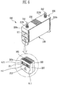
- FIG. 6 is a perspective view illustrating an assembly where the jelly roll 100 and the current collector 200 are connected to each other.
- the two mandrel protrusions 111 of the jelly roll 100 are inserted into the mandrel protrusion accommodating holes 212 formed in the side plates 210a and 210b of the current collector 200, so that the jelly roll 100 and the current collector 200 are connected.
- a jelly roll guide 215 is provided to guide the inserted jelly roll 100 and to prevent detachment of the positive and negative non-applied parts 162 and 172 formed on opposite sides of the jelly roll 100 after the jelly roll 100 is connected.
- the jelly roll guide 215 extends from opposite sides (or edges) S11 and S22 of the side plates 210a and 210b toward a direction along the extending direction of the cap plates 210c and 210d.
- the inside positive or negative non-applied part 162 and 172 may be seen through the adhesive inlet 211, and the mandrel protrusions 111 inserted from the inside may be seen through the mandrel protrusion accommodating holes 212.
- the electrode terminals 241 and 242 are designed to be electrically connected to external electrical devices.
- FIG. 7 is a schematic view illustrating a process of applying the adhesive.
- an auxiliary side plate 400 is provided parallel with one of the side plates 210a and 210b side by side.
- a predetermined amount of an adhesive 420 is applied onto the auxiliary side plate 400, and the adhesive 420 is spread on up to the side plates 210a and 210b using a blade 410.
- the adhesive 420 is put onto the jelly roll 100 through the mandrel protrusion accommodating holes 212 and the adhesive inlet 211.
- the adhesive 420 may be an electrically conductive adhesive.
- the adhesive 420 may attach or adhere the positive side plate 210a to the positive non-applied part 162, and attach or adhere the negative side plate 210b to the negative non-applied part 172.
- the adhesive 420 may attach or adhere the positive auxiliary current collector 110a to the positive non-applied part 162 and attach or adhere the negative auxiliary current collector 110b to the negative non-applied part 172.
- a conductive connection member may be additionally provided to respectively electrically connect the non-applied parts 162 and 172 of the electrode plate 150 with the auxiliary current collectors 110a and 110b or to respectively electrically connect the non-applied parts 162 and 172 of the electrode plate 150 with the side plates 210a and 210b.
- the conductive adhesive 420 After applying the conductive adhesive 420, the conductive adhesive 420 is heated via ultraviolet irradiation or the like so as not to damage a separator of a secondary battery and then the conductive adhesive 420 is hardened at a low temperature.
- the mandrel protrusion accommodating holes 212 and the mandrel protrusions 111 inserted into the mandrel protrusion accommodating holes 212 are welded before injecting the adhesive 420.
Landscapes
- Chemical & Material Sciences (AREA)
- Chemical Kinetics & Catalysis (AREA)
- Electrochemistry (AREA)
- General Chemical & Material Sciences (AREA)
- Engineering & Computer Science (AREA)
- Manufacturing & Machinery (AREA)
- Materials Engineering (AREA)
- Secondary Cells (AREA)
- Cell Electrode Carriers And Collectors (AREA)
Claims (12)
- Electrode de type roulé comprenant :un premier collecteur de courant auxiliaire et un deuxième collecteur de courant auxiliaire, le premier collecteur de courant auxiliaire comprenant une première protubérance de mandrin disposée sur une première partie d'extrémité et le deuxième collecteur de courant auxiliaire comprenant une deuxième protubérance de mandrin disposée sur une deuxième partie d'extrémité, et les première et deuxième protubérances de mandrin faisant saillie à l'opposé l'une de l'autre ;une couche d'isolement de mandrin isolant électriquement le premier collecteur de courant auxiliaire du deuxième collecteur de courant auxiliaire et isolant les premier et deuxième collecteurs de courant auxiliaires de l'extérieur des premier et deuxième collecteurs de courant auxiliaires ; etune plaque d'électrode comprenant une première plaque d'électrode, une deuxième plaque d'électrode et un séparateur interposé entre la première et la deuxième plaque d'électrode afin d'isoler électriquement la première plaque d'électrode de la deuxième plaque d'électrode, la plaque d'électrode étant disposée sur une surface extérieure de la couche d'isolement de mandrin,dans laquelle le premier collecteur de courant auxiliaire et le deuxième collecteur de courant auxiliaire sont enroulés avec la plaque d'électrode de sorte que seules les protubérances de mandrin soient exposées.
- Electrode de type roulé selon la revendication 1, dans laquelle la première plaque d'électrode comprend une couche de matériau actif positif à laquelle un matériau actif positif est appliqué et une partie sans matériau actif positif à laquelle le matériau actif positif n'est pas appliqué, la deuxième plaque d'électrode comprend une couche de matériau actif négatif à laquelle un matériau actif négatif est appliqué et une partie sans matériau actif négatif à laquelle le matériau actif négatif n'est pas appliqué, et
les première et deuxième plaques d'électrode sont disposées avec la partie sans matériau actif positif exposée à un bord du séparateur et avec la partie sans matériau actif négatif exposée à un autre bord opposé du séparateur. - Electrode de type roulé selon la revendication 2, dans laquelle le premier collecteur de courant auxiliaire comprend un alliage d'au moins l'un de l'aluminium, du nickel, du titane et d'un carbone plastique.
- Electrode de type roulé selon la revendication 2 ou 3, dans laquelle le deuxième collecteur de courant auxiliaire comprend un alliage d'au moins l'un du cuivre, de l'acier inoxydable, de l'aluminium et du nickel.
- Electrode de type roulé selon l'une quelconque des revendications précédentes, dans laquelle deux protubérances de mandrin ou plus sont formées sur chacun des premier et deuxième collecteurs de courant auxiliaires.
- Ensemble d'électrode, comprenant :une électrode de type roulé selon l'une quelconque des revendications précédentes ;un premier collecteur de courant principal et un deuxième collecteur de courant principal, comprenant chacun une plaque latérale et une plaque de recouvrement s'étendant perpendiculairement d'un bord de la plaque latérale, la plaque latérale comprenant un trou de réception de protubérance de mandrin recevant chacune des protubérances de mandrin, et la plaque de recouvrement comprenant une borne d'électrode ; etune partie d'isolement de collecteur de courant reliant physiquement la plaque de recouvrement du premier collecteur de courant principal à la plaque de recouvrement du deuxième collecteur de courant principal, et isolant électriquement le premier collecteur de courant principal du deuxième collecteur de courant principal.
- Ensemble d'électrode selon la revendication 6, dans lequel une entrée d'adhésif pour injecter un adhésif est formée dans chacune de la plaque latérale du premier collecteur de courant principal et de la plaque latérale du deuxième collecteur de courant principal.
- Ensemble d'électrode selon la revendication 7, comprenant un adhésif électriquement conducteur injecté dans les entrées d'adhésif.
- Ensemble d'électrode selon la revendication 8, dans lequel l'adhésif fait adhérer le premier collecteur de courant principal à la partie sans matériau actif positif et fait adhérer le deuxième collecteur de courant principal à la partie sans matériau actif négatif.
- Ensemble d'électrode selon la revendication 8 ou 9, dans lequel l'adhésif fait adhérer le premier collecteur de courant auxiliaire à la partie sans matériau actif positif et fait adhérer le deuxième collecteur de courant auxiliaire à la partie sans matériau actif négatif.
- Ensemble d'électrode selon la revendication 7, lorsqu'elle dépend de la revendication 5, dans lequel au moins une entrée d'adhésif est prévue entre les protubérances de mandrin situées sur au moins l'un des premier et deuxième collecteurs de courant auxiliaires.
- Ensemble d'électrode selon l'une des revendications 6 à 11, dans lequel le trou de réception de protubérance de mandrin et les protubérances de mandrin insérées dans le trou de réception de protubérance de mandrin sont soudés les uns avec les autres.
Applications Claiming Priority (1)
| Application Number | Priority Date | Filing Date | Title |
|---|---|---|---|
| KR1020100080290A KR101199205B1 (ko) | 2010-08-19 | 2010-08-19 | 젤리 롤 및 이를 구비한 전극 조립체 |
Publications (2)
| Publication Number | Publication Date |
|---|---|
| EP2421074A1 EP2421074A1 (fr) | 2012-02-22 |
| EP2421074B1 true EP2421074B1 (fr) | 2016-03-23 |
Family
ID=44533979
Family Applications (1)
| Application Number | Title | Priority Date | Filing Date |
|---|---|---|---|
| EP11178172.0A Active EP2421074B1 (fr) | 2010-08-19 | 2011-08-19 | Electrodes de type roulé et ensemble formant électrode doté de celui-ci |
Country Status (4)
| Country | Link |
|---|---|
| US (1) | US9040188B2 (fr) |
| EP (1) | EP2421074B1 (fr) |
| KR (1) | KR101199205B1 (fr) |
| CN (1) | CN102376938B (fr) |
Families Citing this family (1)
| Publication number | Priority date | Publication date | Assignee | Title |
|---|---|---|---|---|
| SE546430C2 (en) * | 2022-09-16 | 2024-10-29 | Northvolt Ab | A method of manufacturing a secondary cell |
Family Cites Families (21)
| Publication number | Priority date | Publication date | Assignee | Title |
|---|---|---|---|---|
| US4073210A (en) * | 1976-09-10 | 1978-02-14 | Katsuyuki Totsu | Screw |
| US4539272A (en) | 1983-12-07 | 1985-09-03 | Gte Government Systems Corporation | Electrochemical cell having a plurality of battery stacks |
| EP1213783A1 (fr) | 2000-12-08 | 2002-06-12 | Renata AG | Batterie à électrodes bobinées avec dissipateur de chaleur |
| KR100467690B1 (ko) * | 2001-11-06 | 2005-01-24 | 삼성에스디아이 주식회사 | 이차전지의 전극 젤리 롤용 마감 테이프를 구비한 이차전지의 전극 조합체 |
| CN100438144C (zh) * | 2003-05-26 | 2008-11-26 | 日本电气株式会社 | 二次电池用正极活性材料,二次电池用正极,二次电池及制备二次电池用正极活性材料的方法 |
| JP4588331B2 (ja) | 2004-02-02 | 2010-12-01 | パナソニック株式会社 | 角形電池とその製造方法 |
| KR100599714B1 (ko) | 2004-06-25 | 2006-07-12 | 삼성에스디아이 주식회사 | 이차 전지 |
| KR20060033643A (ko) | 2004-10-15 | 2006-04-19 | 주식회사 에너랜드 | 리벳에 의해 전극탭과 리드선이 접합되는 적층형리튬이차전지의 전극탭 처리방법 |
| JP4553751B2 (ja) | 2005-02-25 | 2010-09-29 | 三洋電機株式会社 | 角型二次電池 |
| JP2008016411A (ja) | 2006-07-10 | 2008-01-24 | Hissho Go | リチウム二次電池の極巻き導電構造 |
| KR101256061B1 (ko) | 2006-07-27 | 2013-04-18 | 삼성에스디아이 주식회사 | 이차 전지 |
| KR100808093B1 (ko) | 2006-07-28 | 2008-03-03 | 피에이치 유 도날드 | 리튬 이차 전지의 전극 조립체용 도전성 구조체 |
| US20080076019A1 (en) | 2006-09-22 | 2008-03-27 | Wu Donald P H | Core Structure for a Square Lithium Secondary Battery |
| JP5260857B2 (ja) | 2006-11-13 | 2013-08-14 | 三洋電機株式会社 | 角形非水電解質二次電池及びその製造方法 |
| TWI377717B (en) * | 2006-12-29 | 2012-11-21 | Ind Tech Res Inst | Nonaqueous electrolyte having maleimide additives and rechargeable cells employing the same |
| KR101154884B1 (ko) | 2007-01-12 | 2012-06-18 | 주식회사 엘지화학 | 상부 절연체가 젤리-롤에 결합되어 있는 이차전지 |
| JP4976174B2 (ja) | 2007-03-26 | 2012-07-18 | 日立ビークルエナジー株式会社 | 密閉型二次電池 |
| DE102007000428A1 (de) * | 2007-08-07 | 2009-02-19 | Dilo Trading Ag | Wickeldorn, Lithium-Ionen-Zelle und Verfahren zur Polung einer Lithium-Ionen-Zelle mittels eines Wickeldorns |
| JP5242364B2 (ja) | 2008-12-19 | 2013-07-24 | 日立ビークルエナジー株式会社 | 扁平形二次電池 |
| CN201397861Y (zh) | 2009-03-31 | 2010-02-03 | 天津力神电池股份有限公司 | 一种方形锂离子电池卷针 |
| JP5211086B2 (ja) | 2010-02-08 | 2013-06-12 | 日立ビークルエナジー株式会社 | 二次電池 |
-
2010
- 2010-08-19 KR KR1020100080290A patent/KR101199205B1/ko active Active
-
2011
- 2011-06-03 US US13/152,542 patent/US9040188B2/en active Active
- 2011-08-19 CN CN201110240041.4A patent/CN102376938B/zh active Active
- 2011-08-19 EP EP11178172.0A patent/EP2421074B1/fr active Active
Also Published As
| Publication number | Publication date |
|---|---|
| CN102376938A (zh) | 2012-03-14 |
| EP2421074A1 (fr) | 2012-02-22 |
| CN102376938B (zh) | 2015-06-24 |
| KR101199205B1 (ko) | 2012-11-07 |
| KR20120017595A (ko) | 2012-02-29 |
| US9040188B2 (en) | 2015-05-26 |
| US20120045674A1 (en) | 2012-02-23 |
Similar Documents
| Publication | Publication Date | Title |
|---|---|---|
| US8974954B2 (en) | Battery | |
| EP2365562B1 (fr) | Ensemble d'électrode et batterie secondaire en disposant | |
| US20210305630A1 (en) | Positive electrode for solid-state battery, manufacturing method for positive electrode for solid-state battery, and solid-state battery | |
| KR101147207B1 (ko) | 전극군과 이를 적용한 이차 전지 | |
| EP3067958B1 (fr) | Ensemble d'électrode et batterie secondaire en disposant | |
| US20100035151A1 (en) | Power storage device, and method for manufacturing power storage device | |
| KR20180082491A (ko) | 나노다공성 세퍼레이터층을 이용한 리튬 배터리 | |
| EP2736102B1 (fr) | Ensemble d'électrode et batterie rechargeable en disposant | |
| US20110104572A1 (en) | Electrode assembly for secondary battery and method of making the electrode assembly | |
| CN114651350B (zh) | 电极组件及其制造方法 | |
| US11552376B2 (en) | Electrode assembly and method for manufacturing the same | |
| US9401499B2 (en) | Electrode assembly and secondary battery having the same | |
| CN208298952U (zh) | 电池及电子设备 | |
| WO2009048303A2 (fr) | Pile électrochimique | |
| US20210020895A1 (en) | Secondary battery and manufacturing method thereof | |
| US7166387B2 (en) | Thin battery with an electrode having a higher strength base portion than a tip portion | |
| KR101084079B1 (ko) | 이차전지 및 이에 적용된 전극군 | |
| KR101515672B1 (ko) | 2 이상의 양극 및 음극을 포함하는 전극 조립체 및 이에 의한 전기 화학 소자 | |
| EP2421074B1 (fr) | Electrodes de type roulé et ensemble formant électrode doté de celui-ci | |
| US20250158134A1 (en) | Electrode plate, electrode assembly and secondary battery | |
| US20260058219A1 (en) | Electrode assembly and secondary battery including the same | |
| EP4641725A1 (fr) | Batterie secondaire et son procédé de fabrication | |
| KR20260045239A (ko) | 전극 조립체 및 이를 포함하는 이차 전지 | |
| JP2024533515A (ja) | エネルギー貯蔵要素 |
Legal Events
| Date | Code | Title | Description |
|---|---|---|---|
| AK | Designated contracting states |
Kind code of ref document: A1 Designated state(s): AL AT BE BG CH CY CZ DE DK EE ES FI FR GB GR HR HU IE IS IT LI LT LU LV MC MK MT NL NO PL PT RO RS SE SI SK SM TR |
|
| AX | Request for extension of the european patent |
Extension state: BA ME |
|
| PUAI | Public reference made under article 153(3) epc to a published international application that has entered the european phase |
Free format text: ORIGINAL CODE: 0009012 |
|
| 17P | Request for examination filed |
Effective date: 20120329 |
|
| 17Q | First examination report despatched |
Effective date: 20150305 |
|
| GRAP | Despatch of communication of intention to grant a patent |
Free format text: ORIGINAL CODE: EPIDOSNIGR1 |
|
| INTG | Intention to grant announced |
Effective date: 20150903 |
|
| GRAS | Grant fee paid |
Free format text: ORIGINAL CODE: EPIDOSNIGR3 |
|
| GRAA | (expected) grant |
Free format text: ORIGINAL CODE: 0009210 |
|
| AK | Designated contracting states |
Kind code of ref document: B1 Designated state(s): AL AT BE BG CH CY CZ DE DK EE ES FI FR GB GR HR HU IE IS IT LI LT LU LV MC MK MT NL NO PL PT RO RS SE SI SK SM TR |
|
| REG | Reference to a national code |
Ref country code: GB Ref legal event code: FG4D |
|
| REG | Reference to a national code |
Ref country code: CH Ref legal event code: EP |
|
| REG | Reference to a national code |
Ref country code: AT Ref legal event code: REF Ref document number: 783931 Country of ref document: AT Kind code of ref document: T Effective date: 20160415 |
|
| REG | Reference to a national code |
Ref country code: IE Ref legal event code: FG4D |
|
| REG | Reference to a national code |
Ref country code: DE Ref legal event code: R096 Ref document number: 602011024256 Country of ref document: DE |
|
| REG | Reference to a national code |
Ref country code: LT Ref legal event code: MG4D |
|
| REG | Reference to a national code |
Ref country code: NL Ref legal event code: MP Effective date: 20160323 |
|
| PG25 | Lapsed in a contracting state [announced via postgrant information from national office to epo] |
Ref country code: GR Free format text: LAPSE BECAUSE OF FAILURE TO SUBMIT A TRANSLATION OF THE DESCRIPTION OR TO PAY THE FEE WITHIN THE PRESCRIBED TIME-LIMIT Effective date: 20160624 Ref country code: FI Free format text: LAPSE BECAUSE OF FAILURE TO SUBMIT A TRANSLATION OF THE DESCRIPTION OR TO PAY THE FEE WITHIN THE PRESCRIBED TIME-LIMIT Effective date: 20160323 Ref country code: HR Free format text: LAPSE BECAUSE OF FAILURE TO SUBMIT A TRANSLATION OF THE DESCRIPTION OR TO PAY THE FEE WITHIN THE PRESCRIBED TIME-LIMIT Effective date: 20160323 Ref country code: NO Free format text: LAPSE BECAUSE OF FAILURE TO SUBMIT A TRANSLATION OF THE DESCRIPTION OR TO PAY THE FEE WITHIN THE PRESCRIBED TIME-LIMIT Effective date: 20160623 |
|
| REG | Reference to a national code |
Ref country code: AT Ref legal event code: MK05 Ref document number: 783931 Country of ref document: AT Kind code of ref document: T Effective date: 20160323 |
|
| REG | Reference to a national code |
Ref country code: FR Ref legal event code: PLFP Year of fee payment: 6 |
|
| PG25 | Lapsed in a contracting state [announced via postgrant information from national office to epo] |
Ref country code: NL Free format text: LAPSE BECAUSE OF FAILURE TO SUBMIT A TRANSLATION OF THE DESCRIPTION OR TO PAY THE FEE WITHIN THE PRESCRIBED TIME-LIMIT Effective date: 20160323 Ref country code: LT Free format text: LAPSE BECAUSE OF FAILURE TO SUBMIT A TRANSLATION OF THE DESCRIPTION OR TO PAY THE FEE WITHIN THE PRESCRIBED TIME-LIMIT Effective date: 20160323 Ref country code: RS Free format text: LAPSE BECAUSE OF FAILURE TO SUBMIT A TRANSLATION OF THE DESCRIPTION OR TO PAY THE FEE WITHIN THE PRESCRIBED TIME-LIMIT Effective date: 20160323 Ref country code: SE Free format text: LAPSE BECAUSE OF FAILURE TO SUBMIT A TRANSLATION OF THE DESCRIPTION OR TO PAY THE FEE WITHIN THE PRESCRIBED TIME-LIMIT Effective date: 20160323 Ref country code: LV Free format text: LAPSE BECAUSE OF FAILURE TO SUBMIT A TRANSLATION OF THE DESCRIPTION OR TO PAY THE FEE WITHIN THE PRESCRIBED TIME-LIMIT Effective date: 20160323 |
|
| PG25 | Lapsed in a contracting state [announced via postgrant information from national office to epo] |
Ref country code: EE Free format text: LAPSE BECAUSE OF FAILURE TO SUBMIT A TRANSLATION OF THE DESCRIPTION OR TO PAY THE FEE WITHIN THE PRESCRIBED TIME-LIMIT Effective date: 20160323 Ref country code: PL Free format text: LAPSE BECAUSE OF FAILURE TO SUBMIT A TRANSLATION OF THE DESCRIPTION OR TO PAY THE FEE WITHIN THE PRESCRIBED TIME-LIMIT Effective date: 20160323 Ref country code: IS Free format text: LAPSE BECAUSE OF FAILURE TO SUBMIT A TRANSLATION OF THE DESCRIPTION OR TO PAY THE FEE WITHIN THE PRESCRIBED TIME-LIMIT Effective date: 20160723 |
|
| PG25 | Lapsed in a contracting state [announced via postgrant information from national office to epo] |
Ref country code: SM Free format text: LAPSE BECAUSE OF FAILURE TO SUBMIT A TRANSLATION OF THE DESCRIPTION OR TO PAY THE FEE WITHIN THE PRESCRIBED TIME-LIMIT Effective date: 20160323 Ref country code: AT Free format text: LAPSE BECAUSE OF FAILURE TO SUBMIT A TRANSLATION OF THE DESCRIPTION OR TO PAY THE FEE WITHIN THE PRESCRIBED TIME-LIMIT Effective date: 20160323 Ref country code: ES Free format text: LAPSE BECAUSE OF FAILURE TO SUBMIT A TRANSLATION OF THE DESCRIPTION OR TO PAY THE FEE WITHIN THE PRESCRIBED TIME-LIMIT Effective date: 20160323 Ref country code: RO Free format text: LAPSE BECAUSE OF FAILURE TO SUBMIT A TRANSLATION OF THE DESCRIPTION OR TO PAY THE FEE WITHIN THE PRESCRIBED TIME-LIMIT Effective date: 20160323 Ref country code: CZ Free format text: LAPSE BECAUSE OF FAILURE TO SUBMIT A TRANSLATION OF THE DESCRIPTION OR TO PAY THE FEE WITHIN THE PRESCRIBED TIME-LIMIT Effective date: 20160323 Ref country code: SK Free format text: LAPSE BECAUSE OF FAILURE TO SUBMIT A TRANSLATION OF THE DESCRIPTION OR TO PAY THE FEE WITHIN THE PRESCRIBED TIME-LIMIT Effective date: 20160323 Ref country code: PT Free format text: LAPSE BECAUSE OF FAILURE TO SUBMIT A TRANSLATION OF THE DESCRIPTION OR TO PAY THE FEE WITHIN THE PRESCRIBED TIME-LIMIT Effective date: 20160725 |
|
| PG25 | Lapsed in a contracting state [announced via postgrant information from national office to epo] |
Ref country code: BE Free format text: LAPSE BECAUSE OF FAILURE TO SUBMIT A TRANSLATION OF THE DESCRIPTION OR TO PAY THE FEE WITHIN THE PRESCRIBED TIME-LIMIT Effective date: 20160323 Ref country code: IT Free format text: LAPSE BECAUSE OF FAILURE TO SUBMIT A TRANSLATION OF THE DESCRIPTION OR TO PAY THE FEE WITHIN THE PRESCRIBED TIME-LIMIT Effective date: 20160323 |
|
| REG | Reference to a national code |
Ref country code: DE Ref legal event code: R097 Ref document number: 602011024256 Country of ref document: DE |
|
| PLBE | No opposition filed within time limit |
Free format text: ORIGINAL CODE: 0009261 |
|
| STAA | Information on the status of an ep patent application or granted ep patent |
Free format text: STATUS: NO OPPOSITION FILED WITHIN TIME LIMIT |
|
| PG25 | Lapsed in a contracting state [announced via postgrant information from national office to epo] |
Ref country code: DK Free format text: LAPSE BECAUSE OF FAILURE TO SUBMIT A TRANSLATION OF THE DESCRIPTION OR TO PAY THE FEE WITHIN THE PRESCRIBED TIME-LIMIT Effective date: 20160323 |
|
| PG25 | Lapsed in a contracting state [announced via postgrant information from national office to epo] |
Ref country code: BG Free format text: LAPSE BECAUSE OF FAILURE TO SUBMIT A TRANSLATION OF THE DESCRIPTION OR TO PAY THE FEE WITHIN THE PRESCRIBED TIME-LIMIT Effective date: 20160623 |
|
| 26N | No opposition filed |
Effective date: 20170102 |
|
| PG25 | Lapsed in a contracting state [announced via postgrant information from national office to epo] |
Ref country code: MC Free format text: LAPSE BECAUSE OF FAILURE TO SUBMIT A TRANSLATION OF THE DESCRIPTION OR TO PAY THE FEE WITHIN THE PRESCRIBED TIME-LIMIT Effective date: 20160323 |
|
| REG | Reference to a national code |
Ref country code: CH Ref legal event code: PL |
|
| PG25 | Lapsed in a contracting state [announced via postgrant information from national office to epo] |
Ref country code: CH Free format text: LAPSE BECAUSE OF NON-PAYMENT OF DUE FEES Effective date: 20160831 Ref country code: LI Free format text: LAPSE BECAUSE OF NON-PAYMENT OF DUE FEES Effective date: 20160831 |
|
| PG25 | Lapsed in a contracting state [announced via postgrant information from national office to epo] |
Ref country code: SI Free format text: LAPSE BECAUSE OF FAILURE TO SUBMIT A TRANSLATION OF THE DESCRIPTION OR TO PAY THE FEE WITHIN THE PRESCRIBED TIME-LIMIT Effective date: 20160323 |
|
| REG | Reference to a national code |
Ref country code: IE Ref legal event code: MM4A |
|
| REG | Reference to a national code |
Ref country code: FR Ref legal event code: PLFP Year of fee payment: 7 |
|
| PG25 | Lapsed in a contracting state [announced via postgrant information from national office to epo] |
Ref country code: IE Free format text: LAPSE BECAUSE OF NON-PAYMENT OF DUE FEES Effective date: 20160819 |
|
| PG25 | Lapsed in a contracting state [announced via postgrant information from national office to epo] |
Ref country code: LU Free format text: LAPSE BECAUSE OF NON-PAYMENT OF DUE FEES Effective date: 20160819 |
|
| PG25 | Lapsed in a contracting state [announced via postgrant information from national office to epo] |
Ref country code: HU Free format text: LAPSE BECAUSE OF FAILURE TO SUBMIT A TRANSLATION OF THE DESCRIPTION OR TO PAY THE FEE WITHIN THE PRESCRIBED TIME-LIMIT; INVALID AB INITIO Effective date: 20110819 Ref country code: CY Free format text: LAPSE BECAUSE OF FAILURE TO SUBMIT A TRANSLATION OF THE DESCRIPTION OR TO PAY THE FEE WITHIN THE PRESCRIBED TIME-LIMIT Effective date: 20160323 |
|
| PG25 | Lapsed in a contracting state [announced via postgrant information from national office to epo] |
Ref country code: MK Free format text: LAPSE BECAUSE OF FAILURE TO SUBMIT A TRANSLATION OF THE DESCRIPTION OR TO PAY THE FEE WITHIN THE PRESCRIBED TIME-LIMIT Effective date: 20160323 Ref country code: MT Free format text: LAPSE BECAUSE OF NON-PAYMENT OF DUE FEES Effective date: 20160831 Ref country code: TR Free format text: LAPSE BECAUSE OF FAILURE TO SUBMIT A TRANSLATION OF THE DESCRIPTION OR TO PAY THE FEE WITHIN THE PRESCRIBED TIME-LIMIT Effective date: 20160323 |
|
| REG | Reference to a national code |
Ref country code: FR Ref legal event code: PLFP Year of fee payment: 8 |
|
| PG25 | Lapsed in a contracting state [announced via postgrant information from national office to epo] |
Ref country code: AL Free format text: LAPSE BECAUSE OF FAILURE TO SUBMIT A TRANSLATION OF THE DESCRIPTION OR TO PAY THE FEE WITHIN THE PRESCRIBED TIME-LIMIT Effective date: 20160323 |
|
| REG | Reference to a national code |
Ref country code: DE Ref legal event code: R079 Ref document number: 602011024256 Country of ref document: DE Free format text: PREVIOUS MAIN CLASS: H01M0002260000 Ipc: H01M0050531000 |
|
| P01 | Opt-out of the competence of the unified patent court (upc) registered |
Effective date: 20230528 |
|
| PGFP | Annual fee paid to national office [announced via postgrant information from national office to epo] |
Ref country code: DE Payment date: 20250805 Year of fee payment: 15 |
|
| PGFP | Annual fee paid to national office [announced via postgrant information from national office to epo] |
Ref country code: GB Payment date: 20250731 Year of fee payment: 15 |
|
| PGFP | Annual fee paid to national office [announced via postgrant information from national office to epo] |
Ref country code: FR Payment date: 20250808 Year of fee payment: 15 |