EP2421475B1 - Prothèse de hanche électrique - Google Patents
Prothèse de hanche électrique Download PDFInfo
- Publication number
- EP2421475B1 EP2421475B1 EP10701327.8A EP10701327A EP2421475B1 EP 2421475 B1 EP2421475 B1 EP 2421475B1 EP 10701327 A EP10701327 A EP 10701327A EP 2421475 B1 EP2421475 B1 EP 2421475B1
- Authority
- EP
- European Patent Office
- Prior art keywords
- hip joint
- joint prosthesis
- end cap
- electrode
- cap assembly
- Prior art date
- Legal status (The legal status is an assumption and is not a legal conclusion. Google has not performed a legal analysis and makes no representation as to the accuracy of the status listed.)
- Not-in-force
Links
Images

Classifications
-
- A—HUMAN NECESSITIES
- A61—MEDICAL OR VETERINARY SCIENCE; HYGIENE
- A61F—FILTERS IMPLANTABLE INTO BLOOD VESSELS; PROSTHESES; DEVICES PROVIDING PATENCY TO, OR PREVENTING COLLAPSING OF, TUBULAR STRUCTURES OF THE BODY, e.g. STENTS; ORTHOPAEDIC, NURSING OR CONTRACEPTIVE DEVICES; FOMENTATION; TREATMENT OR PROTECTION OF EYES OR EARS; BANDAGES, DRESSINGS OR ABSORBENT PADS; FIRST-AID KITS
- A61F2/00—Filters implantable into blood vessels; Prostheses, i.e. artificial substitutes or replacements for parts of the body; Appliances for connecting them with the body; Devices providing patency to, or preventing collapsing of, tubular structures of the body, e.g. stents
- A61F2/02—Prostheses implantable into the body
- A61F2/30—Joints
- A61F2/32—Joints for the hip
- A61F2/36—Femoral heads ; Femoral endoprostheses
- A61F2/3662—Femoral shafts
- A61F2/367—Proximal or metaphyseal parts of shafts
-
- A—HUMAN NECESSITIES
- A61—MEDICAL OR VETERINARY SCIENCE; HYGIENE
- A61F—FILTERS IMPLANTABLE INTO BLOOD VESSELS; PROSTHESES; DEVICES PROVIDING PATENCY TO, OR PREVENTING COLLAPSING OF, TUBULAR STRUCTURES OF THE BODY, e.g. STENTS; ORTHOPAEDIC, NURSING OR CONTRACEPTIVE DEVICES; FOMENTATION; TREATMENT OR PROTECTION OF EYES OR EARS; BANDAGES, DRESSINGS OR ABSORBENT PADS; FIRST-AID KITS
- A61F2/00—Filters implantable into blood vessels; Prostheses, i.e. artificial substitutes or replacements for parts of the body; Appliances for connecting them with the body; Devices providing patency to, or preventing collapsing of, tubular structures of the body, e.g. stents
- A61F2/02—Prostheses implantable into the body
- A61F2/30—Joints
- A61F2/30721—Accessories
- A61F2/30744—End caps, e.g. for closing an endoprosthetic cavity
-
- A—HUMAN NECESSITIES
- A61—MEDICAL OR VETERINARY SCIENCE; HYGIENE
- A61F—FILTERS IMPLANTABLE INTO BLOOD VESSELS; PROSTHESES; DEVICES PROVIDING PATENCY TO, OR PREVENTING COLLAPSING OF, TUBULAR STRUCTURES OF THE BODY, e.g. STENTS; ORTHOPAEDIC, NURSING OR CONTRACEPTIVE DEVICES; FOMENTATION; TREATMENT OR PROTECTION OF EYES OR EARS; BANDAGES, DRESSINGS OR ABSORBENT PADS; FIRST-AID KITS
- A61F2/00—Filters implantable into blood vessels; Prostheses, i.e. artificial substitutes or replacements for parts of the body; Appliances for connecting them with the body; Devices providing patency to, or preventing collapsing of, tubular structures of the body, e.g. stents
- A61F2/02—Prostheses implantable into the body
- A61F2/48—Operating or control means, e.g. from outside the body, control of sphincters
- A61F2/482—Electrical means
-
- A—HUMAN NECESSITIES
- A61—MEDICAL OR VETERINARY SCIENCE; HYGIENE
- A61F—FILTERS IMPLANTABLE INTO BLOOD VESSELS; PROSTHESES; DEVICES PROVIDING PATENCY TO, OR PREVENTING COLLAPSING OF, TUBULAR STRUCTURES OF THE BODY, e.g. STENTS; ORTHOPAEDIC, NURSING OR CONTRACEPTIVE DEVICES; FOMENTATION; TREATMENT OR PROTECTION OF EYES OR EARS; BANDAGES, DRESSINGS OR ABSORBENT PADS; FIRST-AID KITS
- A61F2/00—Filters implantable into blood vessels; Prostheses, i.e. artificial substitutes or replacements for parts of the body; Appliances for connecting them with the body; Devices providing patency to, or preventing collapsing of, tubular structures of the body, e.g. stents
- A61F2/02—Prostheses implantable into the body
- A61F2/28—Bones
- A61F2002/2821—Bone stimulation by electromagnetic fields or electric current for enhancing ossification
-
- A—HUMAN NECESSITIES
- A61—MEDICAL OR VETERINARY SCIENCE; HYGIENE
- A61F—FILTERS IMPLANTABLE INTO BLOOD VESSELS; PROSTHESES; DEVICES PROVIDING PATENCY TO, OR PREVENTING COLLAPSING OF, TUBULAR STRUCTURES OF THE BODY, e.g. STENTS; ORTHOPAEDIC, NURSING OR CONTRACEPTIVE DEVICES; FOMENTATION; TREATMENT OR PROTECTION OF EYES OR EARS; BANDAGES, DRESSINGS OR ABSORBENT PADS; FIRST-AID KITS
- A61F2/00—Filters implantable into blood vessels; Prostheses, i.e. artificial substitutes or replacements for parts of the body; Appliances for connecting them with the body; Devices providing patency to, or preventing collapsing of, tubular structures of the body, e.g. stents
- A61F2/02—Prostheses implantable into the body
- A61F2/30—Joints
- A61F2002/30001—Additional features of subject-matter classified in A61F2/28, A61F2/30 and subgroups thereof
- A61F2002/30316—The prosthesis having different structural features at different locations within the same prosthesis; Connections between prosthetic parts; Special structural features of bone or joint prostheses not otherwise provided for
- A61F2002/30329—Connections or couplings between prosthetic parts, e.g. between modular parts; Connecting elements
- A61F2002/30331—Connections or couplings between prosthetic parts, e.g. between modular parts; Connecting elements made by longitudinally pushing a protrusion into a complementarily-shaped recess, e.g. held by friction fit
- A61F2002/30332—Conically- or frustoconically-shaped protrusion and recess
-
- A—HUMAN NECESSITIES
- A61—MEDICAL OR VETERINARY SCIENCE; HYGIENE
- A61F—FILTERS IMPLANTABLE INTO BLOOD VESSELS; PROSTHESES; DEVICES PROVIDING PATENCY TO, OR PREVENTING COLLAPSING OF, TUBULAR STRUCTURES OF THE BODY, e.g. STENTS; ORTHOPAEDIC, NURSING OR CONTRACEPTIVE DEVICES; FOMENTATION; TREATMENT OR PROTECTION OF EYES OR EARS; BANDAGES, DRESSINGS OR ABSORBENT PADS; FIRST-AID KITS
- A61F2/00—Filters implantable into blood vessels; Prostheses, i.e. artificial substitutes or replacements for parts of the body; Appliances for connecting them with the body; Devices providing patency to, or preventing collapsing of, tubular structures of the body, e.g. stents
- A61F2/02—Prostheses implantable into the body
- A61F2/30—Joints
- A61F2002/30001—Additional features of subject-matter classified in A61F2/28, A61F2/30 and subgroups thereof
- A61F2002/30316—The prosthesis having different structural features at different locations within the same prosthesis; Connections between prosthetic parts; Special structural features of bone or joint prostheses not otherwise provided for
- A61F2002/30329—Connections or couplings between prosthetic parts, e.g. between modular parts; Connecting elements
- A61F2002/30476—Connections or couplings between prosthetic parts, e.g. between modular parts; Connecting elements locked by an additional locking mechanism
- A61F2002/30507—Connections or couplings between prosthetic parts, e.g. between modular parts; Connecting elements locked by an additional locking mechanism using a threaded locking member, e.g. a locking screw or a set screw
-
- A—HUMAN NECESSITIES
- A61—MEDICAL OR VETERINARY SCIENCE; HYGIENE
- A61F—FILTERS IMPLANTABLE INTO BLOOD VESSELS; PROSTHESES; DEVICES PROVIDING PATENCY TO, OR PREVENTING COLLAPSING OF, TUBULAR STRUCTURES OF THE BODY, e.g. STENTS; ORTHOPAEDIC, NURSING OR CONTRACEPTIVE DEVICES; FOMENTATION; TREATMENT OR PROTECTION OF EYES OR EARS; BANDAGES, DRESSINGS OR ABSORBENT PADS; FIRST-AID KITS
- A61F2/00—Filters implantable into blood vessels; Prostheses, i.e. artificial substitutes or replacements for parts of the body; Appliances for connecting them with the body; Devices providing patency to, or preventing collapsing of, tubular structures of the body, e.g. stents
- A61F2/02—Prostheses implantable into the body
- A61F2/30—Joints
- A61F2002/30001—Additional features of subject-matter classified in A61F2/28, A61F2/30 and subgroups thereof
- A61F2002/30667—Features concerning an interaction with the environment or a particular use of the prosthesis
- A61F2002/30668—Means for transferring electromagnetic energy to implants
-
- A—HUMAN NECESSITIES
- A61—MEDICAL OR VETERINARY SCIENCE; HYGIENE
- A61F—FILTERS IMPLANTABLE INTO BLOOD VESSELS; PROSTHESES; DEVICES PROVIDING PATENCY TO, OR PREVENTING COLLAPSING OF, TUBULAR STRUCTURES OF THE BODY, e.g. STENTS; ORTHOPAEDIC, NURSING OR CONTRACEPTIVE DEVICES; FOMENTATION; TREATMENT OR PROTECTION OF EYES OR EARS; BANDAGES, DRESSINGS OR ABSORBENT PADS; FIRST-AID KITS
- A61F2/00—Filters implantable into blood vessels; Prostheses, i.e. artificial substitutes or replacements for parts of the body; Appliances for connecting them with the body; Devices providing patency to, or preventing collapsing of, tubular structures of the body, e.g. stents
- A61F2/02—Prostheses implantable into the body
- A61F2/30—Joints
- A61F2002/30001—Additional features of subject-matter classified in A61F2/28, A61F2/30 and subgroups thereof
- A61F2002/30667—Features concerning an interaction with the environment or a particular use of the prosthesis
- A61F2002/30668—Means for transferring electromagnetic energy to implants
- A61F2002/3067—Means for transferring electromagnetic energy to implants for data transfer
-
- A—HUMAN NECESSITIES
- A61—MEDICAL OR VETERINARY SCIENCE; HYGIENE
- A61F—FILTERS IMPLANTABLE INTO BLOOD VESSELS; PROSTHESES; DEVICES PROVIDING PATENCY TO, OR PREVENTING COLLAPSING OF, TUBULAR STRUCTURES OF THE BODY, e.g. STENTS; ORTHOPAEDIC, NURSING OR CONTRACEPTIVE DEVICES; FOMENTATION; TREATMENT OR PROTECTION OF EYES OR EARS; BANDAGES, DRESSINGS OR ABSORBENT PADS; FIRST-AID KITS
- A61F2/00—Filters implantable into blood vessels; Prostheses, i.e. artificial substitutes or replacements for parts of the body; Appliances for connecting them with the body; Devices providing patency to, or preventing collapsing of, tubular structures of the body, e.g. stents
- A61F2/02—Prostheses implantable into the body
- A61F2/30—Joints
- A61F2002/30001—Additional features of subject-matter classified in A61F2/28, A61F2/30 and subgroups thereof
- A61F2002/30667—Features concerning an interaction with the environment or a particular use of the prosthesis
- A61F2002/30677—Means for introducing or releasing pharmaceutical products, e.g. antibiotics, into the body
-
- A—HUMAN NECESSITIES
- A61—MEDICAL OR VETERINARY SCIENCE; HYGIENE
- A61F—FILTERS IMPLANTABLE INTO BLOOD VESSELS; PROSTHESES; DEVICES PROVIDING PATENCY TO, OR PREVENTING COLLAPSING OF, TUBULAR STRUCTURES OF THE BODY, e.g. STENTS; ORTHOPAEDIC, NURSING OR CONTRACEPTIVE DEVICES; FOMENTATION; TREATMENT OR PROTECTION OF EYES OR EARS; BANDAGES, DRESSINGS OR ABSORBENT PADS; FIRST-AID KITS
- A61F2/00—Filters implantable into blood vessels; Prostheses, i.e. artificial substitutes or replacements for parts of the body; Appliances for connecting them with the body; Devices providing patency to, or preventing collapsing of, tubular structures of the body, e.g. stents
- A61F2/02—Prostheses implantable into the body
- A61F2/30—Joints
- A61F2002/30001—Additional features of subject-matter classified in A61F2/28, A61F2/30 and subgroups thereof
- A61F2002/30667—Features concerning an interaction with the environment or a particular use of the prosthesis
- A61F2002/30677—Means for introducing or releasing pharmaceutical products, e.g. antibiotics, into the body
- A61F2002/3068—Means for introducing or releasing pharmaceutical products, e.g. antibiotics, into the body the pharmaceutical product being in a reservoir
-
- A—HUMAN NECESSITIES
- A61—MEDICAL OR VETERINARY SCIENCE; HYGIENE
- A61F—FILTERS IMPLANTABLE INTO BLOOD VESSELS; PROSTHESES; DEVICES PROVIDING PATENCY TO, OR PREVENTING COLLAPSING OF, TUBULAR STRUCTURES OF THE BODY, e.g. STENTS; ORTHOPAEDIC, NURSING OR CONTRACEPTIVE DEVICES; FOMENTATION; TREATMENT OR PROTECTION OF EYES OR EARS; BANDAGES, DRESSINGS OR ABSORBENT PADS; FIRST-AID KITS
- A61F2/00—Filters implantable into blood vessels; Prostheses, i.e. artificial substitutes or replacements for parts of the body; Appliances for connecting them with the body; Devices providing patency to, or preventing collapsing of, tubular structures of the body, e.g. stents
- A61F2/02—Prostheses implantable into the body
- A61F2/30—Joints
- A61F2/32—Joints for the hip
- A61F2/36—Femoral heads ; Femoral endoprostheses
- A61F2/3662—Femoral shafts
- A61F2002/3678—Geometrical features
- A61F2002/368—Geometrical features with lateral apertures, bores, holes or openings, e.g. for reducing the mass, for receiving fixation screws or for communicating with the inside of a hollow shaft
-
- A—HUMAN NECESSITIES
- A61—MEDICAL OR VETERINARY SCIENCE; HYGIENE
- A61F—FILTERS IMPLANTABLE INTO BLOOD VESSELS; PROSTHESES; DEVICES PROVIDING PATENCY TO, OR PREVENTING COLLAPSING OF, TUBULAR STRUCTURES OF THE BODY, e.g. STENTS; ORTHOPAEDIC, NURSING OR CONTRACEPTIVE DEVICES; FOMENTATION; TREATMENT OR PROTECTION OF EYES OR EARS; BANDAGES, DRESSINGS OR ABSORBENT PADS; FIRST-AID KITS
- A61F2220/00—Fixations or connections for prostheses classified in groups A61F2/00 - A61F2/26 or A61F2/82 or A61F9/00 or A61F11/00 or subgroups thereof
- A61F2220/0025—Connections or couplings between prosthetic parts, e.g. between modular parts; Connecting elements
-
- A—HUMAN NECESSITIES
- A61—MEDICAL OR VETERINARY SCIENCE; HYGIENE
- A61F—FILTERS IMPLANTABLE INTO BLOOD VESSELS; PROSTHESES; DEVICES PROVIDING PATENCY TO, OR PREVENTING COLLAPSING OF, TUBULAR STRUCTURES OF THE BODY, e.g. STENTS; ORTHOPAEDIC, NURSING OR CONTRACEPTIVE DEVICES; FOMENTATION; TREATMENT OR PROTECTION OF EYES OR EARS; BANDAGES, DRESSINGS OR ABSORBENT PADS; FIRST-AID KITS
- A61F2220/00—Fixations or connections for prostheses classified in groups A61F2/00 - A61F2/26 or A61F2/82 or A61F9/00 or A61F11/00 or subgroups thereof
- A61F2220/0025—Connections or couplings between prosthetic parts, e.g. between modular parts; Connecting elements
- A61F2220/0033—Connections or couplings between prosthetic parts, e.g. between modular parts; Connecting elements made by longitudinally pushing a protrusion into a complementary-shaped recess, e.g. held by friction fit
-
- A—HUMAN NECESSITIES
- A61—MEDICAL OR VETERINARY SCIENCE; HYGIENE
- A61F—FILTERS IMPLANTABLE INTO BLOOD VESSELS; PROSTHESES; DEVICES PROVIDING PATENCY TO, OR PREVENTING COLLAPSING OF, TUBULAR STRUCTURES OF THE BODY, e.g. STENTS; ORTHOPAEDIC, NURSING OR CONTRACEPTIVE DEVICES; FOMENTATION; TREATMENT OR PROTECTION OF EYES OR EARS; BANDAGES, DRESSINGS OR ABSORBENT PADS; FIRST-AID KITS
- A61F2250/00—Special features of prostheses classified in groups A61F2/00 - A61F2/26 or A61F2/82 or A61F9/00 or A61F11/00 or subgroups thereof
- A61F2250/0001—Means for transferring electromagnetic energy to implants
-
- A—HUMAN NECESSITIES
- A61—MEDICAL OR VETERINARY SCIENCE; HYGIENE
- A61F—FILTERS IMPLANTABLE INTO BLOOD VESSELS; PROSTHESES; DEVICES PROVIDING PATENCY TO, OR PREVENTING COLLAPSING OF, TUBULAR STRUCTURES OF THE BODY, e.g. STENTS; ORTHOPAEDIC, NURSING OR CONTRACEPTIVE DEVICES; FOMENTATION; TREATMENT OR PROTECTION OF EYES OR EARS; BANDAGES, DRESSINGS OR ABSORBENT PADS; FIRST-AID KITS
- A61F2250/00—Special features of prostheses classified in groups A61F2/00 - A61F2/26 or A61F2/82 or A61F9/00 or A61F11/00 or subgroups thereof
- A61F2250/0001—Means for transferring electromagnetic energy to implants
- A61F2250/0002—Means for transferring electromagnetic energy to implants for data transfer
-
- A—HUMAN NECESSITIES
- A61—MEDICAL OR VETERINARY SCIENCE; HYGIENE
- A61F—FILTERS IMPLANTABLE INTO BLOOD VESSELS; PROSTHESES; DEVICES PROVIDING PATENCY TO, OR PREVENTING COLLAPSING OF, TUBULAR STRUCTURES OF THE BODY, e.g. STENTS; ORTHOPAEDIC, NURSING OR CONTRACEPTIVE DEVICES; FOMENTATION; TREATMENT OR PROTECTION OF EYES OR EARS; BANDAGES, DRESSINGS OR ABSORBENT PADS; FIRST-AID KITS
- A61F2250/00—Special features of prostheses classified in groups A61F2/00 - A61F2/26 or A61F2/82 or A61F9/00 or A61F11/00 or subgroups thereof
- A61F2250/0058—Additional features; Implant or prostheses properties not otherwise provided for
- A61F2250/0067—Means for introducing or releasing pharmaceutical products into the body
- A61F2250/0068—Means for introducing or releasing pharmaceutical products into the body the pharmaceutical product being in a reservoir
-
- A—HUMAN NECESSITIES
- A61—MEDICAL OR VETERINARY SCIENCE; HYGIENE
- A61F—FILTERS IMPLANTABLE INTO BLOOD VESSELS; PROSTHESES; DEVICES PROVIDING PATENCY TO, OR PREVENTING COLLAPSING OF, TUBULAR STRUCTURES OF THE BODY, e.g. STENTS; ORTHOPAEDIC, NURSING OR CONTRACEPTIVE DEVICES; FOMENTATION; TREATMENT OR PROTECTION OF EYES OR EARS; BANDAGES, DRESSINGS OR ABSORBENT PADS; FIRST-AID KITS
- A61F2310/00—Prostheses classified in A61F2/28 or A61F2/30 - A61F2/44 being constructed from or coated with a particular material
- A61F2310/00005—The prosthesis being constructed from a particular material
- A61F2310/00179—Ceramics or ceramic-like structures
- A61F2310/00185—Ceramics or ceramic-like structures based on metal oxides
- A61F2310/00239—Ceramics or ceramic-like structures based on metal oxides containing zirconia or zirconium oxide ZrO2
Definitions
- the invention relates to a hip joint prosthesis with a shaft-shaped insertable into a femur and a proximal end cap assembly which closes a cavity of the hip joint prosthesis.
- Such hip joint prostheses are known in the field of endoprosthetics, for example from the DE 295 06 036 U1 .
- the publication EP 0781532 A2 discloses the features of the preamble of claim 1.
- the problem with such inelastic, tissue-constraining implants is the obstruction of biological recovery, especially through the loss of blood vessels and nerves.
- the biomechanical quality of the support structure suffers from the partial withdrawal of its function.
- MRSA multi-resistant Staphylococcus aureus
- the technique of transmission works according to the transformer principle:
- the injured or diseased body region is characterized by an extremely low frequency sinusoidal magnetic field having a frequency of about 1 to 100 Hz - preferably from 4 to 20 Hz - and a magnetic flux density of 0.5 to 5 mT (5 to 50 Gauss), which is generated by a functional current generator in one or more - primary - outer current coils, into which the implanted body part is introduced.
- These extremely low-frequency electromagnetic fields penetrate the tissue largely loss-free, including any clothing and a cast, as well as the non-magnetic (austenitic) implant metals.
- the so-called transformer implanted.
- the induced in the transmitter electrical potentials are brought so in the area adjacent to the implant tissue effect.
- the invention has for its object to improve an orthopedic implant in the form of a generic hip joint prosthesis, in particular with regard to their handling and flexible usability during surgery, their biological effect, their therapeutic efficacy and their efficiency.
- the invention is based on the generic hip joint prosthesis in that the end cap assembly carries a coil assembly which is connected to a first pole to a first electrode and a second pole to a second electrode in that the first and second electrodes comprise surfaces of the hip joint prosthesis, and in a state in which the end cap assembly closes the lumen of the hip joint prosthesis, the coil assembly is located for the most part in the cavity.
- the end cap preferably has an internal volume in which a pickup coil wound around an iron core is located. This is usefully glued into the end cap assembly.
- the ends of the coil arrangement come into suitable contact with electrically conductive surfaces, which form tissue electrodes. Based on the invention, the end cap thus receives a dual function.
- the end cap accommodates the components that give the hip joint the electrical properties.
- the surgeon can decide during surgery, whether the prosthesis with a conventional end cap or one with the electrical components equipped end cap closes.
- the provision and storage of magnetically-induced end caps are much less expensive and thus more cost-effective than the provision of magnetically inducible hip joint prostheses with the required different dimensions.
- the joint prosthetic implant is particularly suitable as a so-called "spacer", which is implanted in infected artificial hip joints in a two-stage surgery for the sterilization and regeneration of the bone and after the construction of an aseptic, sustainable Bone can be replaced again against an individual joint prosthesis.
- a neck portion connected proximally to the shaft-shaped portion and carrying a femoral head at least part of the cavity, the cavity in the neck portion fully or nearly completely receiving the end cap assembly and inserting a fastener and a tool for securing the neck portion to the neck shaft-shaped portion allowed, and the end cap assembly seals the cavity of the neck portion proximally.
- the cavity of the neck portion is replaced by a double function. On the one hand it allows the insertion of a fastener, in particular a screw, and a tool for attaching the neck portion to the shaft-shaped portion, but on the other hand, it also provides enough space to accommodate the end cap assembly completely or almost completely in the interior of the implant.
- the outer dimensions of the implant are kept low in this way, since the electrification no enlargement of the implant is required.
- the first electrode is formed by a contact surface of the end cap assembly and that the second electrode is formed by a contact surface of the shaft-shaped portion.
- the end cap assembly may be wholly or partially made of an insulating ceramic, wherein an electrically conductive surface area may be realized by the application of electrically conductive material.
- the first electrode is formed by a contact surface of the end cap assembly and that the second electrode is formed by a contact surface of the neck portion. If for some reason it is desired to avoid the propagation of the electric field in the region of the shaft-shaped section, this arrangement of the electrodes is particularly useful.
- the first electrode is formed by a contact surface of the end cap assembly and that the second electrode is formed by a contact surface of the shaft-shaped portion and the neck portion.
- the neck portion is in electrical contact with the shaft-shaped portion, the entirety of the shaft portion and neck portion which form one electrode while the other electrode is formed by a surface of the end cap assembly.
- the first electrode is formed by a contact surface of the neck portion and that the second electrode is formed by a contact surface of the shaft-shaped portion.
- the end cap is thus not part of the electrode assembly, but the electrodes are formed by the neck portion and the shaft-shaped portion.
- the neck portion is connected to the shaft-shaped portion by an axially disposed electrically insulating screw.
- an axially disposed electrically insulating screw For example, a zirconia (ZrO 2 ) screw can be used.
- a drug reservoir is disposed, which contains a drug, and that the cavity is connected to an outer region of the hip joint prosthesis via openings that allow a transfer of the drug from the cavity to the outside.
- the medicament reservoir contains an antibiotic.
- the device according to the invention thus enables in this way a local antibiosis by the activation of low-viscosity antibiotic solutions on the surface of the implant and in the immediately adjacent cooking and soft tissue. This is of particular advantage since antibiosis can be activated by the electromagnetic fields applied during the therapy.
- the medicament-related aspect of the invention is, for example, executable such that the medicament reservoir is at least partially formed by a pressure-permeable container which at least partially dispenses its contents upon closure of the cavity with the end cap assembly.
- the end cap assembly prefferably supports the pressure-permeable container.
- an antibiotic filled annular tube is inserted prior to implantation, or is carried by the end cap assembly, for example, by being placed on a tapered end of the end cap assembly.
- a thin solution of an antibiotic is within the pressure-permeable tube.
- the wall of the hose ring consists of a thin elastic plastic, which under light pressure when inserting the end cap, in particular so when screwing the end cap, is permeable to the solution.
- the medicament reservoir to cooperate with a controllable device, whereby the medicament can be dispensed at least partially by activating the device.
- the drug in particular the antibiotic, can thereby be delivered selectively at any time; the delivery is therefore not limited to that at the time of implantation.
- controllable device is suitable for converting an externally generated magnetic pulse directly or indirectly into mechanical energy, which causes the delivery of the drug.
- a magnetic pulse may be translated into mechanical energy with the assistance of permanent magnetic or ferromagnetic movable components to effect delivery of the drug.
- the magnetic pulse is detected by a device and then converted by circuit technology into a signal for generating mechanical energy of an actuator.
- controllable device comprises an electrical energy storage, a receiver, an electrical control circuit and an actuator drivable by the electrical control circuit, so that the delivery of the drug can be effected by a signal generated externally.
- the drivable actuator may in particular be part of a medicament pump.
- the electrical energy store is an accumulator which can be charged by an electrical voltage induced in the coil arrangement.
- the variant with electrical energy storage is also suitable for long-term use, since the accumulator at any time by an externally applied magnetic field, which is anyway used in the context of therapy, rechargeable and thus can provide the energy for driving the drug pump.
- FIG. 1 shows an exploded perspective view of a hip joint prosthesis 10 according to the invention.
- the hip joint prosthesis 10 has a shaft-shaped portion 12, a neck portion 28, a femoral head 30 and an end cap assembly 14.
- the neck portion 28 is connected to the shaft-shaped portion 12 by means of a screw 32.
- the end cap assembly 14 has an external thread 40 by means of which it can be screwed into an internal thread 42 of the neck portion 28.
- Within the end cap assembly 14 are disposed electrical components associated with the FIGS. 2 and 3 be explained in more detail. One pole of these electrical components is electrically connected to a spring 44, which is of the End cap assembly 14 is worn.
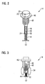
- FIG. 2 shows an exploded perspective view of an end cap assembly 14 of a hip joint prosthesis 10 according to the invention
- FIG. 3 shows an axial section through an end cap assembly 14 of a hip joint prosthesis 10 according to the invention.
- the end cap assembly 14 has a cavity 46. In this cavity 46 is wound on an iron core 48 coil assembly 18 can be inserted. After insertion of the assembly into the cavity 46, it may be adhered therein, for example, with epoxy resin adhesive, and the cavity 46 may be sealed distally with a plate 50, preferably by adhering the plate 50 to the threadedly tapered threaded portion.
- the metallic plate 50 is in electrical contact with a pole 24 of the coil assembly 18.
- the other pole 20 of the coil assembly 18 communicates with an electrically conductive surface 22 of the end cap assembly 14.
- electrically conductive spring 44 to which in turn an electrically conductive plate 52 is fixed distally. Is the end cap assembly 14 inserted into the hip joint prosthesis, the plate 52 closes an electrical contact with the screw 32 (see FIG. 1 ).
- the body 40 carrying the thread 40 of the end cap assembly 14 may be made electrically insulating, preferably of an alumina or zirconia ceramic (Al 2 O 3 or ZrO 2 ).
- a portion of the surface of the end cap assembly is then transferred to an electrically conductive state, such as by sputtering or vapor deposition with electrically conductive material.
- the metallic plate 52 is in communication with the screw 32 and in turn this both the neck portion 28 and the shaft-shaped portion 12 - both made of electrically conductive metal - contacted, the neck portion 28 and the shaft-shaped portion 12 together form the counter electrode to the electrically conductive surface of the end cap assembly 14. It is also conceivable to provide the screw 32 insulating and also otherwise to ensure that there is no electrical contact between the neck portion 28 and the shaft-shaped portion 12. Then, by electrical contacting, the neck portion 28 or portions of the neck portion 28 alone may form the counter electrode to the end cap assembly 14.
- the electrical contact between the distal pole of the coil assembly and the neck portion 28 can be avoided while making electrical contact between this pole 24 and the shaft-shaped portion. Then, the electrically conductive surface of the end cap assembly 14 and the shaft-shaped portion 12 form counter electrodes without inclusion of the neck portion 28. In another embodiment, it is also possible that the end cap assembly 14 does not serve as an electrode. This can be realized so that the end cap assembly 14 is completely insulating on its surface and the first pole 20 of the coil assembly 18 when screwing the Endkappenan angel 14 in the neck portion 28 contacted this, such as by a crimping contact by means of the collar 46 of the Endkappenan angel.
- FIG. 3 shows a useful embodiment of an end cap assembly 14 with a further functionality.
- the end cap assembly 14 carries a drug reservoir 34.
- This drug reservoir is particularly intended for local antibiosis.
- the outer surface of the drug reservoir 34 is provided as a pressure-permeable wall so that a liquid drug solution may escape as the end cap assembly 14 enters the lumen 16 (see FIG FIG. 1 ) is screwed, since then a compression of the drug reservoir 34 takes place. Liquid exiting the medication reservoir 34 may then exit through the openings 36, 38 from the cavity 16 into the exterior of the hip joint prosthesis 10.
- a drug pump is provided, which directly or indirectly with the coil assembly 18 electrical energy is supplied.
- the coil assembly 18 can charge an accumulator, which then at any time the required electrical energy for the Operation of the drug pump provides.
- the operation of the drug pump can be controlled by a conventional transceiver. It is also conceivable to release the mechanical energy required for the time-controlled release by a component which reacts to a magnetic impulse.
Landscapes
- Health & Medical Sciences (AREA)
- Orthopedic Medicine & Surgery (AREA)
- Cardiology (AREA)
- Oral & Maxillofacial Surgery (AREA)
- Transplantation (AREA)
- Engineering & Computer Science (AREA)
- Biomedical Technology (AREA)
- Heart & Thoracic Surgery (AREA)
- Vascular Medicine (AREA)
- Life Sciences & Earth Sciences (AREA)
- Animal Behavior & Ethology (AREA)
- General Health & Medical Sciences (AREA)
- Public Health (AREA)
- Veterinary Medicine (AREA)
- Prostheses (AREA)
Claims (15)
- Prothèse de hanche (10) avec- un tronçon (12) en forme de tige susceptible d'être introduit dans un fémur et- un dispositif de capuchon de terminaison (14), placé du côté proximal qui ferme une cavité (16) de la prothèse de hanche (10),- le dispositif de capuchon de terminaison (14) portant un dispositif de bobine (18) qui par un premier pôle (20) est relié avec une première électrode (22) et par un deuxième pôle (24) est relié avec une deuxième électrode (26),- la première et la deuxième électrodes (22, 26) englobant des surfaces de la prothèse de hanche (10),- dans une position dans laquelle le dispositif de capuchon de terminaison (14) ferme la cavité (16) de la prothèse de hanche (10), le dispositif de bobine (18) étant placé en majeure partie dans la cavité (16),caractérisée en ce
qu'il est prévu un tronçon de col (28) relié côté proximal avec le tronçon (12) en forme de tige, portant une tête fémorale (30), comportant au moins une partie de la cavité, la cavité (16) dans le tronçon de col (28) réceptionnant totalement ou presque totalement le dispositif de capuchon de terminaison (14) et permettant l'introduction d'un moyen de fixation (32) et d'un outil pour la fixation du tronçon de col (28) sur le tronçon (12) en forme de tige et en ce que- le dispositif de capuchon de terminaison (14) ferme la cavité (16) du tronçon de col (28) du côté proximal. - Prothèse de hanche (10) selon la revendication 1, caractérisée en ce que- la première électrode (22) est formée par une surface de contact du dispositif de capuchon de terminaison (14) et- en ce que la deuxième électrode (26) est formée par une surface de contact du tronçon (12) en forme de tige.
- Prothèse de hanche (10) selon la revendication 2, caractérisée en ce que- la première électrode (22) est formée par une surface de contact du dispositif de capuchon de terminaison (14) et- en ce que la deuxième électrode (26') est formée par une surface de contact du tronçon de col (28).
- Prothèse de hanche (10) selon la revendication 1,
caractérisée en ce que- la première électrode (22) est formée par une surface de contact du dispositif de capuchon de terminaison et- en ce que la deuxième électrode (26, 26') est formée par une surface de contact du tronçon en forme de tige et du tronçon de col. - Prothèse de hanche (10) selon la revendication 1, caractérisée en ce que- la première électrode (22) est formée par une surface de contact du tronçon de col (28) et- en ce que la deuxième électrode (26, 26') est formée par une surface de contact du tronçon (12) en forme de tige.
- Prothèse de hanche (10) selon la revendication 5, caractérisée en ce que le tronçon de col (28) est relié avec le tronçon (12) en forme de tige par une vis isolante électrique (32) placée en direction axiale.
- Prothèse de hanche (10) selon l'une quelconque des revendications précédentes, caractérisée en ce que- dans la cavité (16) est placé un réservoir à médicament (34) qui contient un médicament et- en ce que la cavité (16) est reliée avec une région extérieure de la prothèse de hanche (10) par l'intermédiaire d'orifices (36, 38) qui admettent un passage du médicament de la cavité (16) dans la région extérieure.
- Prothèse de hanche (10) selon la revendication 7, caractérisée en ce que le réservoir à médicament (34) contient un antibiotique.
- Prothèse de hanche (10) selon la revendication 7 ou la revendication 8, caractérisée en ce que le médicament est fluide.
- Prothèse de hanche (10) selon la revendication 7 ou la revendication 8, caractérisée en ce que le réservoir à médicament (34) est formé au moins en partie par un récipient perméable à la pression, lequel lors de la fermeture de la cavité (16) avec le dispositif de capuchon de terminaison (14) distribue au moins en partie son contenu.
- Prothèse de hanche (10) selon la revendication 10, caractérisée en ce que le dispositif de capuchon de terminaison (14) porte le récipient (34) perméable à la pression.
- Prothèse de hanche (10) selon l'une quelconque des revendications 7 à 11, caractérisée en ce que le réservoir à médicament (34) interagit avec un système amorçable, le médicament pouvant, par amorçage du système, être distribué au moins en partie.
- Prothèse de hanche (10) selon la revendication 12, caractérisée en ce que le système amorçable est apte à transformer directement ou indirectement une impulsion magnétique générée à l'extérieur du corps en une énergie mécanique, laquelle provoque la distribution du médicament.
- Prothèse de hanche (10) selon la revendication 12 ou la revendication 13, caractérisée en ce que le système amorçable comporte un accumulateur d'énergie électrique, un récepteur, un circuit de commande électrique et un actionneur susceptible d'être activé par le circuit de commande électrique, de sorte que par un signal généré en externe du corps, la distribution du médicament puisse être provoquée.
- Prothèse de hanche (10) selon la revendication 14, caractérisée en ce que l'accumulateur d'énergie électrique est un accumulateur qui peut être chargé par une tension électrique induite dans le dispositif de bobine.
Applications Claiming Priority (2)
| Application Number | Priority Date | Filing Date | Title |
|---|---|---|---|
| DE102009007195A DE102009007195A1 (de) | 2009-02-03 | 2009-02-03 | Elektrische Hüftgelenkprothese |
| PCT/EP2010/000465 WO2010089044A1 (fr) | 2009-02-03 | 2010-01-26 | Prothèse de hanche électrique |
Publications (2)
| Publication Number | Publication Date |
|---|---|
| EP2421475A1 EP2421475A1 (fr) | 2012-02-29 |
| EP2421475B1 true EP2421475B1 (fr) | 2016-09-07 |
Family
ID=42199520
Family Applications (1)
| Application Number | Title | Priority Date | Filing Date |
|---|---|---|---|
| EP10701327.8A Not-in-force EP2421475B1 (fr) | 2009-02-03 | 2010-01-26 | Prothèse de hanche électrique |
Country Status (5)
| Country | Link |
|---|---|
| US (1) | US9962263B2 (fr) |
| EP (1) | EP2421475B1 (fr) |
| AU (1) | AU2010211300A1 (fr) |
| DE (1) | DE102009007195A1 (fr) |
| WO (1) | WO2010089044A1 (fr) |
Families Citing this family (6)
| Publication number | Priority date | Publication date | Assignee | Title |
|---|---|---|---|---|
| DE102010051929A1 (de) | 2010-11-19 | 2012-05-24 | Neue Magnetodyn Gmbh | System und Verfahren zum Überführen einer medizinischen Apparatur in einen funktionsfähigen Zustand |
| DE102012025143A1 (de) | 2012-11-07 | 2014-05-08 | Heraeus Medical Gmbh | Verfahren zur Wirkstofffreisetzung und Wirkstofffreisetzungssysteme |
| DE102014108261A1 (de) * | 2014-06-12 | 2016-01-07 | Universität Rostock | Implantat |
| NL2020034B1 (en) * | 2017-12-07 | 2019-06-19 | Gyromotics B V | Prosthesis |
| EP3815649A1 (fr) * | 2019-10-28 | 2021-05-05 | Klinikum rechts der Isar der Technischen Universität München | Espaceur endoprothétique de théragnostic |
| CN118203458B (zh) * | 2024-05-22 | 2024-08-13 | 北京贝思达生物技术有限公司 | 一种抗感染型髋关节假体股骨柄 |
Family Cites Families (24)
| Publication number | Priority date | Publication date | Assignee | Title |
|---|---|---|---|---|
| DE2315517C2 (de) * | 1972-04-05 | 1983-11-10 | Werner Dipl.-Ing. 8000 München Kraus | Hüftgelenkkopfprothese |
| US4216548A (en) | 1976-03-19 | 1980-08-12 | Werner Kraus | Long-term endoprosthesis |
| DE2611744C2 (de) | 1976-03-19 | 1982-01-28 | Werner Dipl.-Ing. 8000 Muenchen Kraus | Einrichtung zur Vitalerhaltung von Knochengewebe für Endoprothesen |
| DE3709734C2 (de) | 1987-03-25 | 1996-06-27 | Kraus Werner | Elektro-Stimulationsgerät für eine liegende Endoprothese |
| US5030236A (en) * | 1989-06-19 | 1991-07-09 | Intermedics Orthopedics, Inc. | Apparatus for enhancing biointegration of bony and endoprosthesis structures |
| US5645740A (en) * | 1993-11-01 | 1997-07-08 | Naiman; Charles S. | System and assemblage for producing microtexturized substrates and implants |
| DE4421154B4 (de) | 1994-06-10 | 2005-01-05 | Biomet Merck Deutschland Gmbh | Schaftprothese |
| DE29506036U1 (de) | 1995-04-07 | 1995-06-01 | Brehm, Peter, 91085 Weisendorf | Modulares Femurprothesensystem mit einem Schaft bzw. Prothesennagel, auf welchen verschiedene Module aufsetzbar sind |
| DE19544750A1 (de) | 1995-11-30 | 1997-06-05 | Christoph Rehberg | Implantierbare Vorrichtung mit Innenelektrode zur Förderung des Gewebewachstums |
| CA2229382A1 (fr) * | 1996-06-18 | 1997-12-24 | Marc D. Grynpas | Dispositif de fixation d'une prothese dans une cavite osseuse et ses procedes d'utilisation |
| DE19928449C1 (de) * | 1999-06-23 | 2001-03-08 | Geot Ges Fuer Elektro Oseto Th | Knochenschraube mit Vorrichtung zur Elektrostimulation |
| US6610096B2 (en) * | 2001-08-22 | 2003-08-26 | Macdonald Stuart G. | Prosthetic implants having enhanced utility |
| IL154184A0 (en) * | 2003-01-29 | 2003-07-31 | Univ Ramot | Self powered osteogenesis and osseointegration promotion and maintenance device for endesseous implants |
| US9445901B2 (en) * | 2003-03-12 | 2016-09-20 | Deger C. Tunc | Prosthesis with sustained release analgesic |
| US7190273B2 (en) * | 2003-07-11 | 2007-03-13 | Depuy Products, Inc. | Joint endoprosthesis with ambient condition sensing |
| US7033399B2 (en) * | 2003-08-22 | 2006-04-25 | Ortho Innovations, Inc. | Welded hip prosthesis |
| US20050137711A1 (en) * | 2003-12-19 | 2005-06-23 | Southworth Carleton B. | Pre-stressed implant |
| DE102004024473B4 (de) | 2004-05-14 | 2010-06-17 | Neue Magnetodyn Gmbh | Hüftkopfkappenimplantat mit Vorrichtung zur elektrischen Gewebestimulation |
| US7455695B2 (en) * | 2004-06-28 | 2008-11-25 | Depuy Products, Inc. | Modular prosthesis and locking nut therefor |
| US20060004431A1 (en) * | 2004-07-01 | 2006-01-05 | Fuller Thomas A | Prophylactic bactericidal implant |
| CA2583911A1 (fr) * | 2004-10-28 | 2006-05-11 | Microchips, Inc. | Implants orthopediques et dentaires pour le relargage regle de medicaments |
| DE102006005224B4 (de) * | 2006-01-31 | 2008-09-04 | P + P Medical Gmbh | Vorrichtung zur Trennung einer aus einem elektrisch leitfähigen Material bestehenden Gelenkendoprothese von biologischen und/oder biokompatiblen Materialien |
| DE102006032957B4 (de) * | 2006-05-01 | 2008-08-07 | Neue Magnetodyn Gmbh | Stimulationsvorrichtung für die Osteosynthese und die Endoprothetik |
| GB0618612D0 (en) * | 2006-09-21 | 2006-11-01 | Smith & Nephew | Medical device |
-
2009
- 2009-02-03 DE DE102009007195A patent/DE102009007195A1/de not_active Withdrawn
-
2010
- 2010-01-26 AU AU2010211300A patent/AU2010211300A1/en not_active Abandoned
- 2010-01-26 EP EP10701327.8A patent/EP2421475B1/fr not_active Not-in-force
- 2010-01-26 US US13/147,715 patent/US9962263B2/en active Active
- 2010-01-26 WO PCT/EP2010/000465 patent/WO2010089044A1/fr not_active Ceased
Also Published As
| Publication number | Publication date |
|---|---|
| US20120041565A1 (en) | 2012-02-16 |
| US9962263B2 (en) | 2018-05-08 |
| DE102009007195A1 (de) | 2010-08-05 |
| AU2010211300A1 (en) | 2011-09-29 |
| EP2421475A1 (fr) | 2012-02-29 |
| WO2010089044A1 (fr) | 2010-08-12 |
Similar Documents
| Publication | Publication Date | Title |
|---|---|---|
| EP2012869B1 (fr) | Dispositif de stimulation pour ostéosynthèse et endoprothèse | |
| EP1847227A1 (fr) | Système de clou électrique | |
| DE69533407T2 (de) | Wirbelsäulenfusionsimplantat | |
| EP2421475B1 (fr) | Prothèse de hanche électrique | |
| EP1408857B1 (fr) | Vis a os pourvue d'un dispositif d'electrostimulation | |
| EP1895936B1 (fr) | Implant bactericide prophylactique | |
| JP4175899B2 (ja) | 磁気駆動可能な髄内装置 | |
| DE102012015483B3 (de) | Elektrodenanordnung für eine Plasmabehandlung und Vorrichtung zur Herstellung einer transkutanen Verbindung | |
| DE20020649U1 (de) | Vorrichtung für den chirurgischen oder therapeutischen Gebrauch, insbesondere Implantate und chirurgische Instrumente sowie deren Zubehör | |
| US20100298886A1 (en) | Contact Device for Osteosynthesis | |
| WO2000045724A1 (fr) | Vis a os | |
| DE102007049542A1 (de) | Implantierbare Vorrichtung, System zum Erzeugen lokalisierter elektromagnetischer Felder im Bereich eines Implantats und Spulenanordnung | |
| DE3417773A1 (de) | Vorrichtung zur herstellung pulsierender magnetfelder fuer therapeutische zwecke | |
| EP0071658B1 (fr) | Dispositif pour le maintien de la vitalité de tissus osseux | |
| DE19508753A1 (de) | Implantierbare Vorrichtung für Gelenkersatz-, Osteosynthese- oder Dentalzwecke | |
| WO2009010303A2 (fr) | Système d'administration de substances actives à un organisme, dispositifs d'utilisation d'un tel système et procédé de fabrication de tels dispositifs | |
| EP2512589A1 (fr) | Dispositif permettant d'administrer des médicaments et d'influencer les effets de médicaments | |
| EP2317948B1 (fr) | Dispositif implant pour distraction tissulaire et/ou osseuse | |
| DE102014108261A1 (de) | Implantat | |
| EP4371580A1 (fr) | Accessoire pour le nettoyage d'implants |
Legal Events
| Date | Code | Title | Description |
|---|---|---|---|
| PUAI | Public reference made under article 153(3) epc to a published international application that has entered the european phase |
Free format text: ORIGINAL CODE: 0009012 |
|
| 17P | Request for examination filed |
Effective date: 20111212 |
|
| AK | Designated contracting states |
Kind code of ref document: A1 Designated state(s): AT BE BG CH CY CZ DE DK EE ES FI FR GB GR HR HU IE IS IT LI LT LU LV MC MK MT NL NO PL PT RO SE SI SK SM TR |
|
| DAX | Request for extension of the european patent (deleted) | ||
| RIN1 | Information on inventor provided before grant (corrected) |
Inventor name: MILITZ, MATTHIAS Inventor name: STEPHAN, HERIBERT Inventor name: KRAUS, STEPHANIE Inventor name: KRAUS, WERNER |
|
| GRAP | Despatch of communication of intention to grant a patent |
Free format text: ORIGINAL CODE: EPIDOSNIGR1 |
|
| RIC1 | Information provided on ipc code assigned before grant |
Ipc: A61F 2/30 20060101ALI20150831BHEP Ipc: A61F 2/36 20060101AFI20150831BHEP Ipc: A61F 2/48 20060101ALI20150831BHEP Ipc: A61F 2/28 20060101ALI20150831BHEP |
|
| INTG | Intention to grant announced |
Effective date: 20150923 |
|
| GRAS | Grant fee paid |
Free format text: ORIGINAL CODE: EPIDOSNIGR3 |
|
| GRAA | (expected) grant |
Free format text: ORIGINAL CODE: 0009210 |
|
| AK | Designated contracting states |
Kind code of ref document: B1 Designated state(s): AT BE BG CH CY CZ DE DK EE ES FI FR GB GR HR HU IE IS IT LI LT LU LV MC MK MT NL NO PL PT RO SE SI SK SM TR |
|
| REG | Reference to a national code |
Ref country code: GB Ref legal event code: FG4D Free format text: NOT ENGLISH |
|
| REG | Reference to a national code |
Ref country code: CH Ref legal event code: EP |
|
| REG | Reference to a national code |
Ref country code: IE Ref legal event code: FG4D Free format text: LANGUAGE OF EP DOCUMENT: GERMAN |
|
| REG | Reference to a national code |
Ref country code: AT Ref legal event code: REF Ref document number: 826142 Country of ref document: AT Kind code of ref document: T Effective date: 20161015 |
|
| REG | Reference to a national code |
Ref country code: DE Ref legal event code: R096 Ref document number: 502010012346 Country of ref document: DE |
|
| REG | Reference to a national code |
Ref country code: LT Ref legal event code: MG4D |
|
| REG | Reference to a national code |
Ref country code: NL Ref legal event code: MP Effective date: 20160907 |
|
| PG25 | Lapsed in a contracting state [announced via postgrant information from national office to epo] |
Ref country code: NO Free format text: LAPSE BECAUSE OF FAILURE TO SUBMIT A TRANSLATION OF THE DESCRIPTION OR TO PAY THE FEE WITHIN THE PRESCRIBED TIME-LIMIT Effective date: 20161207 Ref country code: HR Free format text: LAPSE BECAUSE OF FAILURE TO SUBMIT A TRANSLATION OF THE DESCRIPTION OR TO PAY THE FEE WITHIN THE PRESCRIBED TIME-LIMIT Effective date: 20160907 Ref country code: FI Free format text: LAPSE BECAUSE OF FAILURE TO SUBMIT A TRANSLATION OF THE DESCRIPTION OR TO PAY THE FEE WITHIN THE PRESCRIBED TIME-LIMIT Effective date: 20160907 Ref country code: LT Free format text: LAPSE BECAUSE OF FAILURE TO SUBMIT A TRANSLATION OF THE DESCRIPTION OR TO PAY THE FEE WITHIN THE PRESCRIBED TIME-LIMIT Effective date: 20160907 |
|
| PG25 | Lapsed in a contracting state [announced via postgrant information from national office to epo] |
Ref country code: GR Free format text: LAPSE BECAUSE OF FAILURE TO SUBMIT A TRANSLATION OF THE DESCRIPTION OR TO PAY THE FEE WITHIN THE PRESCRIBED TIME-LIMIT Effective date: 20161208 Ref country code: NL Free format text: LAPSE BECAUSE OF FAILURE TO SUBMIT A TRANSLATION OF THE DESCRIPTION OR TO PAY THE FEE WITHIN THE PRESCRIBED TIME-LIMIT Effective date: 20160907 Ref country code: LV Free format text: LAPSE BECAUSE OF FAILURE TO SUBMIT A TRANSLATION OF THE DESCRIPTION OR TO PAY THE FEE WITHIN THE PRESCRIBED TIME-LIMIT Effective date: 20160907 Ref country code: ES Free format text: LAPSE BECAUSE OF FAILURE TO SUBMIT A TRANSLATION OF THE DESCRIPTION OR TO PAY THE FEE WITHIN THE PRESCRIBED TIME-LIMIT Effective date: 20160907 Ref country code: SE Free format text: LAPSE BECAUSE OF FAILURE TO SUBMIT A TRANSLATION OF THE DESCRIPTION OR TO PAY THE FEE WITHIN THE PRESCRIBED TIME-LIMIT Effective date: 20160907 |
|
| PG25 | Lapsed in a contracting state [announced via postgrant information from national office to epo] |
Ref country code: RO Free format text: LAPSE BECAUSE OF FAILURE TO SUBMIT A TRANSLATION OF THE DESCRIPTION OR TO PAY THE FEE WITHIN THE PRESCRIBED TIME-LIMIT Effective date: 20160907 Ref country code: EE Free format text: LAPSE BECAUSE OF FAILURE TO SUBMIT A TRANSLATION OF THE DESCRIPTION OR TO PAY THE FEE WITHIN THE PRESCRIBED TIME-LIMIT Effective date: 20160907 |
|
| PG25 | Lapsed in a contracting state [announced via postgrant information from national office to epo] |
Ref country code: CZ Free format text: LAPSE BECAUSE OF FAILURE TO SUBMIT A TRANSLATION OF THE DESCRIPTION OR TO PAY THE FEE WITHIN THE PRESCRIBED TIME-LIMIT Effective date: 20160907 Ref country code: IS Free format text: LAPSE BECAUSE OF FAILURE TO SUBMIT A TRANSLATION OF THE DESCRIPTION OR TO PAY THE FEE WITHIN THE PRESCRIBED TIME-LIMIT Effective date: 20170107 Ref country code: PL Free format text: LAPSE BECAUSE OF FAILURE TO SUBMIT A TRANSLATION OF THE DESCRIPTION OR TO PAY THE FEE WITHIN THE PRESCRIBED TIME-LIMIT Effective date: 20160907 Ref country code: BG Free format text: LAPSE BECAUSE OF FAILURE TO SUBMIT A TRANSLATION OF THE DESCRIPTION OR TO PAY THE FEE WITHIN THE PRESCRIBED TIME-LIMIT Effective date: 20161207 Ref country code: BE Free format text: LAPSE BECAUSE OF NON-PAYMENT OF DUE FEES Effective date: 20170131 Ref country code: SK Free format text: LAPSE BECAUSE OF FAILURE TO SUBMIT A TRANSLATION OF THE DESCRIPTION OR TO PAY THE FEE WITHIN THE PRESCRIBED TIME-LIMIT Effective date: 20160907 Ref country code: SM Free format text: LAPSE BECAUSE OF FAILURE TO SUBMIT A TRANSLATION OF THE DESCRIPTION OR TO PAY THE FEE WITHIN THE PRESCRIBED TIME-LIMIT Effective date: 20160907 Ref country code: PT Free format text: LAPSE BECAUSE OF FAILURE TO SUBMIT A TRANSLATION OF THE DESCRIPTION OR TO PAY THE FEE WITHIN THE PRESCRIBED TIME-LIMIT Effective date: 20170109 |
|
| REG | Reference to a national code |
Ref country code: DE Ref legal event code: R097 Ref document number: 502010012346 Country of ref document: DE |
|
| PG25 | Lapsed in a contracting state [announced via postgrant information from national office to epo] |
Ref country code: IT Free format text: LAPSE BECAUSE OF FAILURE TO SUBMIT A TRANSLATION OF THE DESCRIPTION OR TO PAY THE FEE WITHIN THE PRESCRIBED TIME-LIMIT Effective date: 20160907 |
|
| PLBE | No opposition filed within time limit |
Free format text: ORIGINAL CODE: 0009261 |
|
| STAA | Information on the status of an ep patent application or granted ep patent |
Free format text: STATUS: NO OPPOSITION FILED WITHIN TIME LIMIT |
|
| REG | Reference to a national code |
Ref country code: FR Ref legal event code: PLFP Year of fee payment: 8 |
|
| PG25 | Lapsed in a contracting state [announced via postgrant information from national office to epo] |
Ref country code: DK Free format text: LAPSE BECAUSE OF FAILURE TO SUBMIT A TRANSLATION OF THE DESCRIPTION OR TO PAY THE FEE WITHIN THE PRESCRIBED TIME-LIMIT Effective date: 20160907 |
|
| 26N | No opposition filed |
Effective date: 20170608 |
|
| PG25 | Lapsed in a contracting state [announced via postgrant information from national office to epo] |
Ref country code: SI Free format text: LAPSE BECAUSE OF FAILURE TO SUBMIT A TRANSLATION OF THE DESCRIPTION OR TO PAY THE FEE WITHIN THE PRESCRIBED TIME-LIMIT Effective date: 20160907 |
|
| REG | Reference to a national code |
Ref country code: CH Ref legal event code: PL |
|
| PG25 | Lapsed in a contracting state [announced via postgrant information from national office to epo] |
Ref country code: MC Free format text: LAPSE BECAUSE OF FAILURE TO SUBMIT A TRANSLATION OF THE DESCRIPTION OR TO PAY THE FEE WITHIN THE PRESCRIBED TIME-LIMIT Effective date: 20160907 |
|
| PG25 | Lapsed in a contracting state [announced via postgrant information from national office to epo] |
Ref country code: CH Free format text: LAPSE BECAUSE OF NON-PAYMENT OF DUE FEES Effective date: 20170131 Ref country code: LI Free format text: LAPSE BECAUSE OF NON-PAYMENT OF DUE FEES Effective date: 20170131 |
|
| REG | Reference to a national code |
Ref country code: IE Ref legal event code: MM4A |
|
| PG25 | Lapsed in a contracting state [announced via postgrant information from national office to epo] |
Ref country code: LU Free format text: LAPSE BECAUSE OF NON-PAYMENT OF DUE FEES Effective date: 20170126 |
|
| REG | Reference to a national code |
Ref country code: FR Ref legal event code: PLFP Year of fee payment: 9 |
|
| REG | Reference to a national code |
Ref country code: BE Ref legal event code: MM Effective date: 20170131 |
|
| PG25 | Lapsed in a contracting state [announced via postgrant information from national office to epo] |
Ref country code: IE Free format text: LAPSE BECAUSE OF NON-PAYMENT OF DUE FEES Effective date: 20170126 |
|
| REG | Reference to a national code |
Ref country code: AT Ref legal event code: MM01 Ref document number: 826142 Country of ref document: AT Kind code of ref document: T Effective date: 20170126 |
|
| PG25 | Lapsed in a contracting state [announced via postgrant information from national office to epo] |
Ref country code: AT Free format text: LAPSE BECAUSE OF NON-PAYMENT OF DUE FEES Effective date: 20170126 |
|
| PG25 | Lapsed in a contracting state [announced via postgrant information from national office to epo] |
Ref country code: MT Free format text: LAPSE BECAUSE OF FAILURE TO SUBMIT A TRANSLATION OF THE DESCRIPTION OR TO PAY THE FEE WITHIN THE PRESCRIBED TIME-LIMIT Effective date: 20160907 |
|
| PG25 | Lapsed in a contracting state [announced via postgrant information from national office to epo] |
Ref country code: HU Free format text: LAPSE BECAUSE OF FAILURE TO SUBMIT A TRANSLATION OF THE DESCRIPTION OR TO PAY THE FEE WITHIN THE PRESCRIBED TIME-LIMIT; INVALID AB INITIO Effective date: 20100126 |
|
| PG25 | Lapsed in a contracting state [announced via postgrant information from national office to epo] |
Ref country code: CY Free format text: LAPSE BECAUSE OF NON-PAYMENT OF DUE FEES Effective date: 20160907 |
|
| PG25 | Lapsed in a contracting state [announced via postgrant information from national office to epo] |
Ref country code: MK Free format text: LAPSE BECAUSE OF FAILURE TO SUBMIT A TRANSLATION OF THE DESCRIPTION OR TO PAY THE FEE WITHIN THE PRESCRIBED TIME-LIMIT Effective date: 20160907 |
|
| PG25 | Lapsed in a contracting state [announced via postgrant information from national office to epo] |
Ref country code: TR Free format text: LAPSE BECAUSE OF FAILURE TO SUBMIT A TRANSLATION OF THE DESCRIPTION OR TO PAY THE FEE WITHIN THE PRESCRIBED TIME-LIMIT Effective date: 20160907 |
|
| PGFP | Annual fee paid to national office [announced via postgrant information from national office to epo] |
Ref country code: GB Payment date: 20220726 Year of fee payment: 13 Ref country code: DE Payment date: 20220727 Year of fee payment: 13 |
|
| PGFP | Annual fee paid to national office [announced via postgrant information from national office to epo] |
Ref country code: FR Payment date: 20220729 Year of fee payment: 13 |
|
| REG | Reference to a national code |
Ref country code: DE Ref legal event code: R119 Ref document number: 502010012346 Country of ref document: DE |
|
| GBPC | Gb: european patent ceased through non-payment of renewal fee |
Effective date: 20230126 |
|
| PG25 | Lapsed in a contracting state [announced via postgrant information from national office to epo] |
Ref country code: GB Free format text: LAPSE BECAUSE OF NON-PAYMENT OF DUE FEES Effective date: 20230126 Ref country code: DE Free format text: LAPSE BECAUSE OF NON-PAYMENT OF DUE FEES Effective date: 20230801 |
|
| PG25 | Lapsed in a contracting state [announced via postgrant information from national office to epo] |
Ref country code: FR Free format text: LAPSE BECAUSE OF NON-PAYMENT OF DUE FEES Effective date: 20230131 |