EP2422735A1 - Dispositif de transport de sang implantable, dispositif de manipulation et dispositif de couplage - Google Patents
Dispositif de transport de sang implantable, dispositif de manipulation et dispositif de couplage Download PDFInfo
- Publication number
- EP2422735A1 EP2422735A1 EP10075373A EP10075373A EP2422735A1 EP 2422735 A1 EP2422735 A1 EP 2422735A1 EP 10075373 A EP10075373 A EP 10075373A EP 10075373 A EP10075373 A EP 10075373A EP 2422735 A1 EP2422735 A1 EP 2422735A1
- Authority
- EP
- European Patent Office
- Prior art keywords
- coupling
- component
- coupling element
- manipulation device
- implantable
- Prior art date
- Legal status (The legal status is an assumption and is not a legal conclusion. Google has not performed a legal analysis and makes no representation as to the accuracy of the status listed.)
- Withdrawn
Links
- 230000008878 coupling Effects 0.000 title claims abstract description 221
- 238000010168 coupling process Methods 0.000 title claims abstract description 221
- 238000005859 coupling reaction Methods 0.000 title claims abstract description 221
- 239000008280 blood Substances 0.000 title claims abstract description 17
- 210000004369 blood Anatomy 0.000 title claims abstract description 17
- 238000000034 method Methods 0.000 claims abstract description 14
- 239000000463 material Substances 0.000 claims abstract description 6
- 239000003550 marker Substances 0.000 claims abstract description 5
- 238000003780 insertion Methods 0.000 claims description 10
- 230000037431 insertion Effects 0.000 claims description 10
- 230000005291 magnetic effect Effects 0.000 claims description 9
- 230000005294 ferromagnetic effect Effects 0.000 claims description 7
- 238000000926 separation method Methods 0.000 claims description 5
- 238000005520 cutting process Methods 0.000 claims description 3
- 241001465754 Metazoa Species 0.000 claims description 2
- 238000006073 displacement reaction Methods 0.000 claims description 2
- 230000001066 destructive effect Effects 0.000 claims 1
- 230000008859 change Effects 0.000 abstract description 2
- 230000013011 mating Effects 0.000 description 15
- 239000000853 adhesive Substances 0.000 description 7
- 230000001070 adhesive effect Effects 0.000 description 7
- 230000000295 complement effect Effects 0.000 description 7
- 239000007943 implant Substances 0.000 description 7
- 230000000747 cardiac effect Effects 0.000 description 5
- 238000002513 implantation Methods 0.000 description 5
- 229920001971 elastomer Polymers 0.000 description 4
- 238000001356 surgical procedure Methods 0.000 description 4
- 239000003814 drug Substances 0.000 description 3
- 239000000806 elastomer Substances 0.000 description 3
- 230000005855 radiation Effects 0.000 description 3
- 238000005452 bending Methods 0.000 description 2
- 239000003822 epoxy resin Substances 0.000 description 2
- 238000001704 evaporation Methods 0.000 description 2
- 230000008020 evaporation Effects 0.000 description 2
- 239000000835 fiber Substances 0.000 description 2
- 238000003384 imaging method Methods 0.000 description 2
- 238000001746 injection moulding Methods 0.000 description 2
- 208000014674 injury Diseases 0.000 description 2
- 238000005304 joining Methods 0.000 description 2
- 238000004519 manufacturing process Methods 0.000 description 2
- 229910052751 metal Inorganic materials 0.000 description 2
- 239000002184 metal Substances 0.000 description 2
- 238000002324 minimally invasive surgery Methods 0.000 description 2
- 229920000647 polyepoxide Polymers 0.000 description 2
- 229920005989 resin Polymers 0.000 description 2
- 239000011347 resin Substances 0.000 description 2
- 229920001169 thermoplastic Polymers 0.000 description 2
- 239000004416 thermosoftening plastic Substances 0.000 description 2
- 230000008733 trauma Effects 0.000 description 2
- 241001631457 Cannula Species 0.000 description 1
- 229910000669 Chrome steel Inorganic materials 0.000 description 1
- VYZAMTAEIAYCRO-UHFFFAOYSA-N Chromium Chemical compound [Cr] VYZAMTAEIAYCRO-UHFFFAOYSA-N 0.000 description 1
- 229910000831 Steel Inorganic materials 0.000 description 1
- 230000009471 action Effects 0.000 description 1
- 238000004026 adhesive bonding Methods 0.000 description 1
- 239000011324 bead Substances 0.000 description 1
- 230000008901 benefit Effects 0.000 description 1
- 230000000903 blocking effect Effects 0.000 description 1
- 239000011248 coating agent Substances 0.000 description 1
- 238000000576 coating method Methods 0.000 description 1
- 150000001875 compounds Chemical class 0.000 description 1
- 239000012141 concentrate Substances 0.000 description 1
- 238000011109 contamination Methods 0.000 description 1
- 238000001816 cooling Methods 0.000 description 1
- 238000004132 cross linking Methods 0.000 description 1
- 238000000354 decomposition reaction Methods 0.000 description 1
- 230000005347 demagnetization Effects 0.000 description 1
- 238000004090 dissolution Methods 0.000 description 1
- 230000005489 elastic deformation Effects 0.000 description 1
- 239000013013 elastic material Substances 0.000 description 1
- 238000005538 encapsulation Methods 0.000 description 1
- 238000005516 engineering process Methods 0.000 description 1
- 239000012530 fluid Substances 0.000 description 1
- 230000012447 hatching Effects 0.000 description 1
- 238000010438 heat treatment Methods 0.000 description 1
- 238000002347 injection Methods 0.000 description 1
- 239000007924 injection Substances 0.000 description 1
- 230000010354 integration Effects 0.000 description 1
- 230000003902 lesion Effects 0.000 description 1
- 238000002844 melting Methods 0.000 description 1
- 230000008018 melting Effects 0.000 description 1
- 229910000510 noble metal Inorganic materials 0.000 description 1
- 210000000056 organ Anatomy 0.000 description 1
- 230000008569 process Effects 0.000 description 1
- 238000005086 pumping Methods 0.000 description 1
- 230000009467 reduction Effects 0.000 description 1
- 230000000717 retained effect Effects 0.000 description 1
- 239000007787 solid Substances 0.000 description 1
- 239000000243 solution Substances 0.000 description 1
- 239000010959 steel Substances 0.000 description 1
- 239000000126 substance Substances 0.000 description 1
- 229910000811 surgical stainless steel Inorganic materials 0.000 description 1
- 238000002604 ultrasonography Methods 0.000 description 1
- 238000009423 ventilation Methods 0.000 description 1
- 230000000007 visual effect Effects 0.000 description 1
- 238000003466 welding Methods 0.000 description 1
Images


Classifications
-
- A—HUMAN NECESSITIES
- A61—MEDICAL OR VETERINARY SCIENCE; HYGIENE
- A61M—DEVICES FOR INTRODUCING MEDIA INTO, OR ONTO, THE BODY; DEVICES FOR TRANSDUCING BODY MEDIA OR FOR TAKING MEDIA FROM THE BODY; DEVICES FOR PRODUCING OR ENDING SLEEP OR STUPOR
- A61M60/00—Blood pumps; Devices for mechanical circulatory actuation; Balloon pumps for circulatory assistance
- A61M60/20—Type thereof
- A61M60/205—Non-positive displacement blood pumps
- A61M60/216—Non-positive displacement blood pumps including a rotating member acting on the blood, e.g. impeller
- A61M60/237—Non-positive displacement blood pumps including a rotating member acting on the blood, e.g. impeller the blood flow through the rotating member having mainly axial components, e.g. axial flow pumps
-
- A—HUMAN NECESSITIES
- A61—MEDICAL OR VETERINARY SCIENCE; HYGIENE
- A61M—DEVICES FOR INTRODUCING MEDIA INTO, OR ONTO, THE BODY; DEVICES FOR TRANSDUCING BODY MEDIA OR FOR TAKING MEDIA FROM THE BODY; DEVICES FOR PRODUCING OR ENDING SLEEP OR STUPOR
- A61M60/00—Blood pumps; Devices for mechanical circulatory actuation; Balloon pumps for circulatory assistance
- A61M60/20—Type thereof
- A61M60/205—Non-positive displacement blood pumps
- A61M60/216—Non-positive displacement blood pumps including a rotating member acting on the blood, e.g. impeller
- A61M60/226—Non-positive displacement blood pumps including a rotating member acting on the blood, e.g. impeller the blood flow through the rotating member having mainly radial components
- A61M60/232—Centrifugal pumps
-
- A—HUMAN NECESSITIES
- A61—MEDICAL OR VETERINARY SCIENCE; HYGIENE
- A61M—DEVICES FOR INTRODUCING MEDIA INTO, OR ONTO, THE BODY; DEVICES FOR TRANSDUCING BODY MEDIA OR FOR TAKING MEDIA FROM THE BODY; DEVICES FOR PRODUCING OR ENDING SLEEP OR STUPOR
- A61M60/00—Blood pumps; Devices for mechanical circulatory actuation; Balloon pumps for circulatory assistance
- A61M60/10—Location thereof with respect to the patient's body
- A61M60/122—Implantable pumps or pumping devices, i.e. the blood being pumped inside the patient's body
-
- A—HUMAN NECESSITIES
- A61—MEDICAL OR VETERINARY SCIENCE; HYGIENE
- A61M—DEVICES FOR INTRODUCING MEDIA INTO, OR ONTO, THE BODY; DEVICES FOR TRANSDUCING BODY MEDIA OR FOR TAKING MEDIA FROM THE BODY; DEVICES FOR PRODUCING OR ENDING SLEEP OR STUPOR
- A61M60/00—Blood pumps; Devices for mechanical circulatory actuation; Balloon pumps for circulatory assistance
- A61M60/10—Location thereof with respect to the patient's body
- A61M60/122—Implantable pumps or pumping devices, i.e. the blood being pumped inside the patient's body
- A61M60/165—Implantable pumps or pumping devices, i.e. the blood being pumped inside the patient's body implantable in, on, or around the heart
- A61M60/178—Implantable pumps or pumping devices, i.e. the blood being pumped inside the patient's body implantable in, on, or around the heart drawing blood from a ventricle and returning the blood to the arterial system via a cannula external to the ventricle, e.g. left or right ventricular assist devices
-
- A—HUMAN NECESSITIES
- A61—MEDICAL OR VETERINARY SCIENCE; HYGIENE
- A61M—DEVICES FOR INTRODUCING MEDIA INTO, OR ONTO, THE BODY; DEVICES FOR TRANSDUCING BODY MEDIA OR FOR TAKING MEDIA FROM THE BODY; DEVICES FOR PRODUCING OR ENDING SLEEP OR STUPOR
- A61M60/00—Blood pumps; Devices for mechanical circulatory actuation; Balloon pumps for circulatory assistance
- A61M60/80—Constructional details other than related to driving
- A61M60/855—Constructional details other than related to driving of implantable pumps or pumping devices
- A61M60/857—Implantable blood tubes
- A61M60/859—Connections therefor
-
- A—HUMAN NECESSITIES
- A61—MEDICAL OR VETERINARY SCIENCE; HYGIENE
- A61M—DEVICES FOR INTRODUCING MEDIA INTO, OR ONTO, THE BODY; DEVICES FOR TRANSDUCING BODY MEDIA OR FOR TAKING MEDIA FROM THE BODY; DEVICES FOR PRODUCING OR ENDING SLEEP OR STUPOR
- A61M60/00—Blood pumps; Devices for mechanical circulatory actuation; Balloon pumps for circulatory assistance
- A61M60/80—Constructional details other than related to driving
- A61M60/855—Constructional details other than related to driving of implantable pumps or pumping devices
- A61M60/865—Devices for guiding or inserting pumps or pumping devices into the patient's body
-
- A—HUMAN NECESSITIES
- A61—MEDICAL OR VETERINARY SCIENCE; HYGIENE
- A61B—DIAGNOSIS; SURGERY; IDENTIFICATION
- A61B17/00—Surgical instruments, devices or methods
- A61B17/34—Trocars; Puncturing needles
- A61B17/3415—Trocars; Puncturing needles for introducing tubes or catheters, e.g. gastrostomy tubes, drain catheters
-
- A—HUMAN NECESSITIES
- A61—MEDICAL OR VETERINARY SCIENCE; HYGIENE
- A61B—DIAGNOSIS; SURGERY; IDENTIFICATION
- A61B17/00—Surgical instruments, devices or methods
- A61B2017/00477—Coupling
-
- A—HUMAN NECESSITIES
- A61—MEDICAL OR VETERINARY SCIENCE; HYGIENE
- A61B—DIAGNOSIS; SURGERY; IDENTIFICATION
- A61B17/00—Surgical instruments, devices or methods
- A61B2017/00831—Material properties
- A61B2017/00876—Material properties magnetic
-
- A—HUMAN NECESSITIES
- A61—MEDICAL OR VETERINARY SCIENCE; HYGIENE
- A61M—DEVICES FOR INTRODUCING MEDIA INTO, OR ONTO, THE BODY; DEVICES FOR TRANSDUCING BODY MEDIA OR FOR TAKING MEDIA FROM THE BODY; DEVICES FOR PRODUCING OR ENDING SLEEP OR STUPOR
- A61M60/00—Blood pumps; Devices for mechanical circulatory actuation; Balloon pumps for circulatory assistance
- A61M60/10—Location thereof with respect to the patient's body
- A61M60/122—Implantable pumps or pumping devices, i.e. the blood being pumped inside the patient's body
- A61M60/126—Implantable pumps or pumping devices, i.e. the blood being pumped inside the patient's body implantable via, into, inside, in line, branching on, or around a blood vessel
- A61M60/148—Implantable pumps or pumping devices, i.e. the blood being pumped inside the patient's body implantable via, into, inside, in line, branching on, or around a blood vessel in line with a blood vessel using resection or like techniques, e.g. permanent endovascular heart assist devices
Definitions
- the invention is in the field of medical technology, in particular implant medicine, and is particularly concerned with the possibilities of implanting components with minimal effort in minimally invasive procedures.
- Implant medicine allows the insertion of various aggregates and elements into a patient's body to replace certain organs and body parts in a temporary or permanent manner or the insertion of certain aggregates to support body functions.
- Such aggregates can usually be brought into place in a simple manner with a wide opening of the patient's body, but a considerable surgical trauma arises.
- the reduction the surgical trauma requires minor intervention, with the openings for introducing components into the body being only slightly larger or, in the case of elastic expansion, partially smaller than the components to be introduced.
- Corresponding aggregates can be introduced in parts and also assembled within the body.
- the minimally invasive insertion often does not allow direct handling of components by hand, so additional instruments such as forceps are used.
- additional instruments such as forceps are used.
- the use of such holding devices is not always easy.
- the components to be implanted are made as small as possible and also rounded in order to disturb as little as possible in the body.
- this brings a difficult handling by appropriate holding devices, such as pliers, with it.
- Even a precise placement or assembling of individual components in the patient's body is difficult. This may be the case particularly in cardiac assist systems when pumps, cannulas, cables and drive components need to be assembled.
- a device with an anchor which can be used close to the heart and which is connected to a guide fiber.
- a hose-like hollow body is displaceable to the armature and can be held there by means of a magnetic device.
- a handling device for a cannula which has a running through the interior of the cannula guide body and for holding the cannula a pillow-like radially expandable holding body. This is so far expandable that it jammed inside the cannula.
- Another object of the solution is a corresponding manipulation device, a coupling device for the mechanical coupling of an implantable component with a manipulation device and the system consisting of the component and the manipulation device, and corresponding methods for connecting the component with a manipulation device and their separation.
- an implantable component according to the invention, a manipulation device for handling such a component, a coupling device for the mechanical coupling of a component with a manipulation device, a system with at least one implantable component and at least one manipulation device, by a corresponding method for connecting an implantable device Component with a manipulation device and by a method for separating a implantable component solved by a manipulation device.
- the invention relates to an implantable component which limits a channel leading to blood within a human or animal body during operation and which, in particular, forms part of a blood delivery device, with a coupling element which is set up for mechanical coupling of a manipulation device.
- such a component can be any component which can be used in a patient's body, in particular a part of a cardiac support system, a blood pump, a valve, a cannula, a catheter, corresponding connection systems between these components and a medicament dosage pump.
- a coupling element is provided according to the invention, which is set up for mechanical coupling of a manipulation device to the component.
- a manipulation device is understood to mean, for example, a surgical instrument which has, for example, a handle on the proximal end facing the surgeon, and a shaft and a distal end which can be connected to the coupling element of the component.
- a further coupling element can be provided for this purpose be, which is connectable to the attached to the implantable component or integrated in this first coupling element.
- a mechanical coupling is provided which permits reliable manipulation of the implantable component from outside the body by means of the manipulation device both at the first implantation and later.
- More than one coupling element can also be arranged on the implantable component in order to be able to use a plurality of manipulation devices or a shared manipulation device, which in this case can also be used to simplify alignment of the implantable component.
- the plurality of coupling elements on the implantable component are spaced from one another on the surface of the implantable component and can also be used to select the most suitable access path depending on the implantation site.
- the coupling element on the component is furthermore set up for the self-holding coupling of a manipulation device.
- the implantable component does not have to be held permanently by manipulation of the manipulation device, as is the case, for example, with various surgical forceps.
- the coupling between the component and the manipulation device is advantageously designed to be self-holding, so that the manipulation device can also be temporarily ignored by the surgeon without the coupling being disengaged.
- the coupling elements are designed so that corresponding coupling forces are developed exclusively between the coupling elements, for example by elastic deformation of one of the coupling elements, without that forces are transmitted via the shaft of the manipulation device.
- the coupling element can be integrated in the component or firmly connected to it.
- the coupling between the component attached to the integrated or in this integrated coupling element and the manipulation device should be particularly easy to be resolved again so that the manipulation device after positioning and mounting of the implantable component readily removable from the patient's body.
- the coupling element itself can be formed, for example, as an internal thread in the implantable component, preferably within a bore, into which a further coupling element in the form of a threaded pin can be screwed.
- the coupling element can also be embodied as a bore or as a group of bores in the component into which bolts of a further coupling element can be inserted.
- Corresponding bolts can for example be made of metal, but also of elastic Materials such as rubber or spring wire, which can be inserted into the corresponding holes non-positively.
- a coupling element can typically also be designed as a groove, for example with an undercut, for example as a dovetail groove, into which a correspondingly complementarily designed body of a further coupling element can be inserted.
- a coupling element Holes or blind holes or other openings with or without undercuts can form a coupling element, wherein the respective complementary coupling element then, for example, a deformable and / or movable body with projections and / or locking elements may have, which cause a coupling and either by means of an actuator can be unlocked or deformable in the application of a tensile force and exceeding a certain release force to separate the coupling elements.
- the coupling elements at least partially made of an elastomer or a spring.
- the manipulation device may include a corresponding coupling element and also a hollow shaft which is coupled to a handle.
- the corresponding actuator for locking lugs or for releasing a screw in the region of the coupling between the coupling elements may be provided, and the actuating member may be actuated in the region of the handle of the manipulation device.
- a coupling element as a cone, in the component, for example a wall of the component, is integrated and in which a further cone is inserted, which forms a second coupling element which is connected to a manipulation device.
- the conical surfaces can be coupled to one another, for example, by an interference fit, but also by means of adhesive or by a vacuum-tight seal. Angled cone clamps can also be used for such a connection.
- the corresponding component-side coupling element attached to the implantable component for example glued to this, welded or soldered or is formed integrally therewith.
- This can be embodied, for example, in that a coupling plate with a threaded bore or an eyelet or a solid body, which in turn can have a bore, a groove, key surfaces or conical surfaces, is fastened to the implantable component.
- the coupling element may for example also be formed as a smooth, surface-smoothed surface on which a serving as a second coupling element suction cup can be placed.
- the suction cup can be by the shaft of the manipulation device, with which it is connected, for example, specifically be ventilated and vented to selectively establish the coupling between the coupling elements and to solve.
- the connection of two smooth coupling surfaces of two coupling elements by means of an adhesive is conceivable, wherein the adhesive for releasing the compound is selectively dissolvable or embrittlable.
- the adhesive may for example be formed as a thermoplastic, which is liquefied for a short time to release the coupling elements from each other, or as a curable resin which is embrittled by radiation crosslinking, for example by UV light, so that the adhesive bond can be easily broken.
- a magnet or a ferromagnetic workpiece may be provided, which is arranged on the outside or in the interior of the component and which cooperates with a magnet or a ferromagnetic part of the manipulation device for coupling.
- a magnet in the component for example, a part a motor or rotor act.
- On the outside of the component can be provided for coupling the manipulation device a mating surface.
- One of the magnets of the coupling device can be designed as a switchable electromagnet.
- a corresponding mating surface can, for example, if it forms part of the component-side coupling element, be configured as a mechanical catching device for the second coupling element associated with the manipulation device and have a recess which has insertion bevels or similar insertion aids for the second coupling element.
- An insertion bevel can be integrated, for example, in an insertion cone, a hollow calotte or another recess tapering towards the interior of the component.
- the second coupling element may optionally have a complementary geometric shape.
- the component can, in particular if the first coupling element as a mating surface, especially with insertion, is formed and in particular when the mating surface itself is not in the immediate vicinity of a ferromagnetic body of the component, but also in all other cases described here, be formed in that the contour of the mating surface can be represented by imaging methods, for example X-ray or ultrasound.
- This is z. B. by a metallic surface coating of the component in the region of the mating surface or by a marker body having a higher density than the wall of the component and is integrated in the immediate vicinity of the mating surface or with a recognizable geometric reference to the mating surface in the component.
- a coupling between a manipulation device is thus possible with a ferromagnetic coupling element and the component easier to produce even without visual contact.
- a coupling element can also be provided on an outer surface of the component an eyelet through which a thread is guided, which serves as a coupling element of the manipulation device.
- a coupling element can also be provided on an outer surface of the component an eyelet through which a thread is guided, which serves as a coupling element of the manipulation device.
- a coupling device accordingly provides a first coupling element, which is assigned to the implantable component, and a second coupling element, which is associated with the manipulation device, wherein the coupling elements are non-positively and / or positively and / or materially connectable or connected to each other.
- the coupling device is advantageously set up so that the coupling is kept stable without external influence.
- the coupling consists of a cohesive connection between the first component and the second component, it can be separated by breaking, cutting or changing the mechanical material properties of at least one part of the coupling device become.
- the change in the mechanical properties of the material for example, embrittlement by radiation or heat or melting a part of the coupling or evaporation, for example by laser action understood.
- the invention relates except to an implantable component, a manipulation device and a coupling device to a corresponding system with one or more components and one or more manipulation devices, which are adapted to be easy to be coupled by means of the coupling elements.
- the corresponding couplings must also be able to be released easily and gently within the patient's body.
- the invention further relates to a method for connecting an implantable component with a manipulation device, wherein the component is mechanically connected to the manipulation device by means of a self-holding, releasable coupling device prior to introduction into the patient's body.
- the component and at least a part of the manipulation device together with the coupling device are manufactured in one piece by injection molding or joined together by a joining process.
- the implantable component can also be releasably screwed, clamped, with the manipulation device, glued or latched, one of the coupling elements cooperating complementary with the other coupling element and wherein, for example, a threaded bore in the component and a corresponding threaded bolt on the manipulation device is arranged and wherein each of the coupling elements can also be provided interchangeable with the respective other part. Therefore, if, for example, an eyelet is provided on the implantable component and a corresponding hook on the manipulation device, then the hook can also be provided on the implantable component and the eyelet on the manipulation device. This also applies to all other embodiments of the coupling elements.
- implantable component and the manipulation devices are already connected to one another before the start of a surgical procedure, this facilitates and accelerates the surgical procedure.
- the separation of the implantable component from the manipulation device can typically take place only after the end of the implantation, for example by mechanical breaking of the coupling device or by other separation of the coupling device.
- the coupling device can be mechanically weakened prior to separation, for example, z. B. by cooling, heating, irradiation, bending or buckling of the coupling device.
- a corresponding resolution of the coupling device can be done for example by cutting or chemical dissolution, decomposition, liquefaction or evaporation of a part of the coupling device.
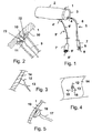
- Fig. 1 shows schematically and stylized an implantable component 1, which is for example a pump for delivering blood as part of a cardiac assist system, with a cylindrical Au- ⁇ enwand 2 of a pump housing and a mounted in the hollow cylinder axial rotor, which is not shown in detail.
- an implantable component 1 which is for example a pump for delivering blood as part of a cardiac assist system, with a cylindrical Au- ⁇ enwand 2 of a pump housing and a mounted in the hollow cylinder axial rotor, which is not shown in detail.
- a coupling element 4 of a manipulation device 5 is fixed and connected to a coupling element, not shown, which is integrated into the component 1.
- the coupling element 4 is connected to a shaft 6 of the manipulation device 5, which is connected at its proximal end with a handle 7.
- a knob 8 is also provided, which may for example be connected to a soul 9, which extends in a cavity of the shaft 6 to the coupling element 4.
- the knob 8 can be moved relative to the handle 7, for example, moved and / or rotated to move the soul 9 relative to the shaft 6, so that the coupling element 4 to operate and, for example, to solve the manipulation device 5 of the component 1.
- Another manipulation device 5 ' is connected via a further coupling element 4' to the component 1 at a different location.
- the further manipulation device 5 ' also has a handle 7' and a knob 8 '.
- the second manipulation device 5 ' can also have a core 9' within a hollow shaft 6 ', which can be moved by means of the knob 8'.
- Fig. 2 shows an exemplary implementation of a coupling device 10 on the component 1 with a blind hole having an internal thread into which a threaded bolt 11 is screwed.
- the threaded bolt 11 as a coupling element of the manipulation device is connected to a core 9, which passes through a hollow shaft 6 and can be rotated in this, to unscrew the threaded bolt 11 in the threaded hole 10 or out of this.
- the shaft 6 on the component 1, the in Fig. 2 only shown in sections, attached and released from this again.
- a coupling element can be formed by a recess, in particular a bore or groove, with an undercut or without an undercut.
- a flange 72 which can be screwed by means of the threaded bolt 11 and a head 73 of the threaded bolt by screwing into the threaded bore 10 on the component 1.
- Fig. 3 schematically shows a coupling element 12 of a manipulation device in the form of a flat, plate-shaped Thermoplastendteils, to which a shaft 13 is attached, which forms part of a manipulation device.
- the plate-shaped part 12 is connected to the planar, for example, a trained and a component-side coupling element forming wall piece 14, for example, welded to this, glued or manufactured in one piece with this as an injection molded part.
- the component 1 can be manipulated until the coupling element 12 aborted by bending the plate 12 on the component 1 is.
- FIG. 4 shown in a plan view, wherein the plate 12 and the shaft 13 can be seen.
- the plate 12 can be bent and removed by pivoting in the direction of the arrows 15, 16.
- the approach of the plate-shaped piece 12 in the wall 14 of the component 1 forms the coupling element integrated there, with which the abknickbare part of the plate 12 is connected as a coupling element of the manipulation device.
- a shaft 17 is connected to a bell-shaped coupling element 18, which is connected to the implantable component 1 by means of a short wire 19.
- the wire 19 ensures that the bell 18 is seated on the component 1 and thus the component 1 can be moved by means of the shaft 17.
- the wire 19 can be turned off or torn off in order to remove the manipulation device 17, 18 from the component 1.
- the coupling elements 18, 19 provide as long as the connection for a good handling of the component 1 via the manipulation device.
- a coupling device is shown with an existing elastomeric coupling element 20 which is connected by means of a shaft 21 with a handle 22 of a manipulation device.
- the Element 20 is frictionally fixed in a bore 23 as a coupling element of an implementable component 1.
- the element 20 can be heated and pressed into the bore 23 to produce a connection of the coupling device 20, 23.
- the manipulation device 20, 21, 22 can be removed from the component 1 by pulling on the shaft 21. It is also conceivable to heat the coupling element 20 in advance or to cool it strongly in order to shrink it.
- Fig. 7 is a coupling device shown with a first component 1, to which a coupling element in the form of a plate 24 placed, for example, welded, soldered or glued.
- the plate 24 may also be embodied as an integral part of the component 1.
- a suction cup 25 is placed, which may for example consist of an elastomer, but also of a hard highly polished plate, for example made of steel.
- the two plates 24, 25 adhere to each other as coupling elements with sufficient surface quality. This is especially the case when one of the components is designed as an elastomeric suction cup.
- a ventilation channel 26 may be provided which extends through the shaft 27 and can be ventilated or evacuated from the proximal end of the manipulation device 25, 26, 27 in order to couple or release the coupling device 24, 25.
- FIG. 8 schematically a portion of an implantable component 51 is shown with a dovetail-like groove 28 and a bore with undercuts.
- a tulip-like coupling element 29 are used with outwardly facing locking lugs which engage elastically in the undercuts of the bore 28.
- the coupling element 29 is connected to a shaft 30 of a manipulation device and can only be pulled out of the bore 28 by sufficient tension on this shaft 30 if a blocking element 51 in the form of a cylinder within a recess 52 in the manipulation device by means of movement of the soul 53 is axially spaced from the locking lugs 29 and thus releases an inward movement of the locking lugs.
- the shaft 30 is hollow to receive the core 53.
- FIG. 10 another constellation of a coupling element 31 is shown, which is also arranged in a bore of the implantable component 1 with undercuts and which is formed substantially cylindrical with outwardly facing locking lugs of elastically bendable end portions of end fingers of the coupling element. Also, the coupling element 31 is firmly seated in the bore 28, but can be pulled out by force applications from this or by pulling the locking lugs of the coupling element 31st
- the Fig. 11 shows a coupling device with a first coupling element 32 and a second coupling element 33, which are each formed plate-shaped.
- the first coupling element 32 is at a portion of a implantable component 1 by gluing, welding or other joining technique attached and has a flat smooth surface on the side facing away from the component 1 side.
- On the surface of the second coupling element 33 is placed and fixed there, for example by means of an adhesive, such as an epoxy resin or other curable resin.
- the coupling elements are connected to each other and the shaft 34 of a manipulation device is connected via this coupling device with the component 1 fixed and self-holding.
- connection can for example be made permanently before introducing the component 1 into a patient's body.
- the epoxy resin between the coupling elements 32, 33 are cured so far that this embrittles so that the coupling elements 32, 33 can be easily separated by breaking.
- the coupling elements 32, 33 are interconnected by a thermoplastic adhesive which is liquefiable by irradiation, for example with a heat source, so that in this way the coupling is resolvable and the manipulation device by separating the second coupling element 33 is removable from the first coupling element 32.
- Ultrasonic pulses or laser beams can also be used to resolve the coupling.
- a constellation is shown, in which a hollow cylindrical component 1 as a coupling element by way of example a dome-shaped mating surface 54 and two cone-shaped mating surfaces 55, 56 has.
- the mating surface 56 of the complementary cone 57 can run parallel to the longitudinal axis of the cylindrical member 1, in the remaining mating surfaces, the complementary body 58, 59 can move radially in it.
- the bodies 57, 58, 59 each represent coupling elements of a manipulation device and can be designed as ferromagnetic bodies, if appropriate as magnets and also as switchable electromagnets.
- the mating surfaces 54, 55, 56 may each be surrounded by ferromagnetic and / or magnetized material of the component 1, as shown by the example of the mating surface 56 by hatching the magnetic region 60.
- a marker body 70 or a surface covering 71 of a fitting surface 54 made of a material of high density, in particular metal, preferably a noble metal, chrome or surgical steel, can be provided ,
- a corresponding solenoid can be switched off or the manipulation device are moved jerkily. It can also be a demagnetization of the magnets by means of an alternating field. However, it is also possible to achieve a different orientation of the magnetic poles relative to each other by rotating the one magnet relative to the other, so that a simplified release is made possible by the occurring magnetic repulsion forces.
- a coupling device is shown with a plate 32 ', which is attached to an implantable component 1 and which has a blind bore 44 with an internal thread.
- the plate 32 'with the blind bore 44 in this case represents a first coupling element of the component 1.
- a second coupling element is connectable, which has a threaded bolt 45 which is connected to a core 46.
- the core 46 extends in the cavity of a shaft 47, which forms part of a manipulating device and proximally with a in Fig. 13 not shown handle is connected.
- the threaded bolt 44 By means of the threaded bolt 44, the shaft 47 and the core 46 are connected to the coupling element 32 'of the implantable component 1.
- the threaded bolt 45 can be unscrewed into the plate 32 'and out of this or the threaded bore 44, in order to produce the coupling, depending on the situation or separate.
- the coupling device is self-holding, ie, on the handle of the manipulation device, not shown, the first component 1 easily moved and positioned as desired or rotated.
- the threaded bolt 47 may be replaced by a female threaded nut connected to the core 46 and the threaded bore 44 replaced by a corresponding threaded bolt.
- the implantable component can also have a wrench surface, for example a hexagonal surface, as a coupling element, on which a complementary key can act as a second coupling element. If this combination is carried out in a press fit, the connection is self-holding.
- a coupling device can also, as in Fig. 14 shown, a combination of an inflatable hollow body, in particular a cushion on the one hand and a gripping surface on the other hand, for example, be provided on the component side.
- a cushion which can be inflated via the shaft of a manipulation device can be introduced into a cavity of a component and inflated there.
- the corresponding cavity may have an undercut.
- the inflatable hollow body can also be formed as a torus 63, 64 and pushed over the component 1 or part 62 of the component and pumped there.
- the pressure in the hollow body can be lowered and thus the coupling device separated.
- the hollow body may be coated for better adhesion to the component and to protect the component surfaces with an elastomer.
- a fluid channel 66 is provided in each case in the shaft 65 of the manipulation device.
- On the component 1 beads 67, 68 may be provided for holding the hollow body, which thus form corresponding mating surfaces as a component-side coupling element.
- the component can be easily positioned and aligned by a surgeon without special effort by means of the manipulating device, without the hand of the surgeon having to be guided directly into the surgical field. This allows a comparatively small access to the surgical field.
- the connection between the instrument or the manipulation device on the one hand and the component on the other hand can already be made before the actual surgical procedure and dissolved after implantation.
Landscapes
- Health & Medical Sciences (AREA)
- Heart & Thoracic Surgery (AREA)
- Engineering & Computer Science (AREA)
- Cardiology (AREA)
- Biomedical Technology (AREA)
- Anesthesiology (AREA)
- Mechanical Engineering (AREA)
- Hematology (AREA)
- Life Sciences & Earth Sciences (AREA)
- Animal Behavior & Ethology (AREA)
- General Health & Medical Sciences (AREA)
- Public Health (AREA)
- Veterinary Medicine (AREA)
- Prostheses (AREA)
- Surgical Instruments (AREA)
Priority Applications (8)
| Application Number | Priority Date | Filing Date | Title |
|---|---|---|---|
| EP10075373A EP2422735A1 (fr) | 2010-08-27 | 2010-08-27 | Dispositif de transport de sang implantable, dispositif de manipulation et dispositif de couplage |
| US13/261,605 US9867916B2 (en) | 2010-08-27 | 2011-08-10 | Implantable blood conveying device, manipulating device and coupling device |
| EP11746479.2A EP2608731B1 (fr) | 2010-08-27 | 2011-08-10 | Dispositif de transport de sang implantable, dispositif de manipulation et dispositif de couplage |
| CN201180041549.XA CN103068334B (zh) | 2010-08-27 | 2011-08-10 | 植入式血液输送装置、操纵装置和联结装置 |
| PCT/EP2011/004063 WO2012025199A1 (fr) | 2010-08-27 | 2011-08-10 | Dispositif de transport de sang implantable, dispositif de manipulation et dispositif de couplage |
| CN201710091484.9A CN107096083A (zh) | 2010-08-27 | 2011-08-10 | 植入式血液输送装置、操纵装置和联结装置 |
| DE112011102828T DE112011102828T5 (de) | 2010-08-27 | 2011-08-10 | Implantierbare Blutfördereinrichtung, Manipulationseinrichtung sowie Koppeleinrichtung |
| US15/834,166 US11083885B2 (en) | 2010-08-27 | 2017-12-07 | Implantable blood conveying device, manipulating device and coupling device |
Applications Claiming Priority (1)
| Application Number | Priority Date | Filing Date | Title |
|---|---|---|---|
| EP10075373A EP2422735A1 (fr) | 2010-08-27 | 2010-08-27 | Dispositif de transport de sang implantable, dispositif de manipulation et dispositif de couplage |
Publications (1)
| Publication Number | Publication Date |
|---|---|
| EP2422735A1 true EP2422735A1 (fr) | 2012-02-29 |
Family
ID=43558361
Family Applications (2)
| Application Number | Title | Priority Date | Filing Date |
|---|---|---|---|
| EP10075373A Withdrawn EP2422735A1 (fr) | 2010-08-27 | 2010-08-27 | Dispositif de transport de sang implantable, dispositif de manipulation et dispositif de couplage |
| EP11746479.2A Active EP2608731B1 (fr) | 2010-08-27 | 2011-08-10 | Dispositif de transport de sang implantable, dispositif de manipulation et dispositif de couplage |
Family Applications After (1)
| Application Number | Title | Priority Date | Filing Date |
|---|---|---|---|
| EP11746479.2A Active EP2608731B1 (fr) | 2010-08-27 | 2011-08-10 | Dispositif de transport de sang implantable, dispositif de manipulation et dispositif de couplage |
Country Status (5)
| Country | Link |
|---|---|
| US (2) | US9867916B2 (fr) |
| EP (2) | EP2422735A1 (fr) |
| CN (2) | CN107096083A (fr) |
| DE (1) | DE112011102828T5 (fr) |
| WO (1) | WO2012025199A1 (fr) |
Cited By (14)
| Publication number | Priority date | Publication date | Assignee | Title |
|---|---|---|---|---|
| CN107206136A (zh) * | 2015-01-22 | 2017-09-26 | Ecp发展有限责任公司 | 包括截留流体内所含磁性颗粒的分离装置以及功能元件的保护装置的导管装置 |
| US10722631B2 (en) | 2018-02-01 | 2020-07-28 | Shifamed Holdings, Llc | Intravascular blood pumps and methods of use and manufacture |
| US11185677B2 (en) | 2017-06-07 | 2021-11-30 | Shifamed Holdings, Llc | Intravascular fluid movement devices, systems, and methods of use |
| US11511103B2 (en) | 2017-11-13 | 2022-11-29 | Shifamed Holdings, Llc | Intravascular fluid movement devices, systems, and methods of use |
| US11654275B2 (en) | 2019-07-22 | 2023-05-23 | Shifamed Holdings, Llc | Intravascular blood pumps with struts and methods of use and manufacture |
| US11724089B2 (en) | 2019-09-25 | 2023-08-15 | Shifamed Holdings, Llc | Intravascular blood pump systems and methods of use and control thereof |
| US11964145B2 (en) | 2019-07-12 | 2024-04-23 | Shifamed Holdings, Llc | Intravascular blood pumps and methods of manufacture and use |
| US12102815B2 (en) | 2019-09-25 | 2024-10-01 | Shifamed Holdings, Llc | Catheter blood pumps and collapsible pump housings |
| US12121713B2 (en) | 2019-09-25 | 2024-10-22 | Shifamed Holdings, Llc | Catheter blood pumps and collapsible blood conduits |
| US12161857B2 (en) | 2018-07-31 | 2024-12-10 | Shifamed Holdings, Llc | Intravascular blood pumps and methods of use |
| US12220570B2 (en) | 2018-10-05 | 2025-02-11 | Shifamed Holdings, Llc | Intravascular blood pumps and methods of use |
| US12409310B2 (en) | 2019-12-11 | 2025-09-09 | Shifamed Holdings, Llc | Descending aorta and vena cava blood pumps |
| US12465748B2 (en) | 2019-08-07 | 2025-11-11 | Supira Medical, Inc. | Catheter blood pumps and collapsible pump housings |
| US12599758B2 (en) | 2019-12-19 | 2026-04-14 | Shifamed Holdings, Llc | Intravascular blood pumps, motors, and fluid control |
Families Citing this family (48)
| Publication number | Priority date | Publication date | Assignee | Title |
|---|---|---|---|---|
| US7393181B2 (en) | 2004-09-17 | 2008-07-01 | The Penn State Research Foundation | Expandable impeller pump |
| JP2009530041A (ja) | 2006-03-23 | 2009-08-27 | ザ・ペン・ステート・リサーチ・ファンデーション | 拡張可能なインペラポンプを有する心臓補助装置 |
| US9138518B2 (en) | 2011-01-06 | 2015-09-22 | Thoratec Corporation | Percutaneous heart pump |
| DE102013008159A1 (de) | 2012-05-14 | 2013-11-14 | Thoratec Corporation | Mantelsystem für Katheterpumpe |
| US8721517B2 (en) | 2012-05-14 | 2014-05-13 | Thoratec Corporation | Impeller for catheter pump |
| US9872947B2 (en) | 2012-05-14 | 2018-01-23 | Tc1 Llc | Sheath system for catheter pump |
| DE102013008168A1 (de) | 2012-05-14 | 2013-11-14 | Thoratec Corporation | Laufrad für Katheterpumpe |
| US9446179B2 (en) | 2012-05-14 | 2016-09-20 | Thoratec Corporation | Distal bearing support |
| US9421311B2 (en) | 2012-07-03 | 2016-08-23 | Thoratec Corporation | Motor assembly for catheter pump |
| US9358329B2 (en) | 2012-07-03 | 2016-06-07 | Thoratec Corporation | Catheter pump |
| EP4186557A1 (fr) | 2012-07-03 | 2023-05-31 | Tc1 Llc | Ensemble motour pour pompe à cathéter |
| JP6530367B2 (ja) | 2013-03-13 | 2019-06-12 | ティーシーワン エルエルシー | 流体導出入システム |
| US11077294B2 (en) | 2013-03-13 | 2021-08-03 | Tc1 Llc | Sheath assembly for catheter pump |
| US11033728B2 (en) | 2013-03-13 | 2021-06-15 | Tc1 Llc | Fluid handling system |
| EP3797810B1 (fr) | 2013-03-15 | 2025-09-03 | Tc1 Llc | Ensemble pompe de cathéter comprenant un stator |
| US9308302B2 (en) | 2013-03-15 | 2016-04-12 | Thoratec Corporation | Catheter pump assembly including a stator |
| EP3131597B1 (fr) | 2014-04-15 | 2020-12-02 | Tc1 Llc | Systèmes d'introduction de pompe de cathéter |
| US9827356B2 (en) | 2014-04-15 | 2017-11-28 | Tc1 Llc | Catheter pump with access ports |
| WO2015160980A1 (fr) | 2014-04-15 | 2015-10-22 | Thoratec Corporation | Pompe cardiaque fournissant un flux de sortie réglable |
| US10583232B2 (en) | 2014-04-15 | 2020-03-10 | Tc1 Llc | Catheter pump with off-set motor position |
| EP3131615B1 (fr) | 2014-04-15 | 2021-06-09 | Tc1 Llc | Capteurs pour pompes de cathéter |
| WO2016028644A1 (fr) | 2014-08-18 | 2016-02-25 | Thoratec Corporation | Eléments de guidage pour une pompe de cathéter percutané |
| WO2016118777A1 (fr) | 2015-01-22 | 2016-07-28 | Thoratec Corporation | Ensemble moteur à masse de rotation réduite pour pompe pour cathéter |
| WO2016118781A2 (fr) | 2015-01-22 | 2016-07-28 | Thoratec Corporation | Ensemble moteur avec échangeur de chaleur pour pompe de cathéter |
| US9675738B2 (en) | 2015-01-22 | 2017-06-13 | Tc1 Llc | Attachment mechanisms for motor of catheter pump |
| DE102016209871A1 (de) | 2016-06-06 | 2017-12-07 | Robert Bosch Gmbh | Stanzvorrichtung und Verfahren zum Stanzen eines Lumens und Implantieren einer Implantateinrichtung |
| US11160970B2 (en) | 2016-07-21 | 2021-11-02 | Tc1 Llc | Fluid seals for catheter pump motor assembly |
| EP3808402A1 (fr) | 2016-07-21 | 2021-04-21 | Tc1 Llc | Chambre remplie de gaz pour ensemble moteur de pompe à cathéter |
| EP3528864B1 (fr) * | 2016-10-20 | 2020-12-30 | Heartware, Inc. | Canule d'entrée |
| CN115040776B (zh) | 2016-10-25 | 2026-03-20 | 马真塔医药有限公司 | 心室辅助装置 |
| EP4039321B1 (fr) | 2018-01-10 | 2026-03-25 | Magenta Medical Ltd. | Dispositif d'assistance ventriculaire |
| DE102018201030B4 (de) | 2018-01-24 | 2025-10-16 | Kardion Gmbh | Magnetkuppelelement mit magnetischer Lagerungsfunktion |
| DE102018206725A1 (de) | 2018-05-02 | 2019-11-07 | Kardion Gmbh | Empfangseinheit, Sendeeinheit, Energieübertragungssystem und Verfahren zur drahtlosen Energieübertragung |
| DE102018206727A1 (de) | 2018-05-02 | 2019-11-07 | Kardion Gmbh | Energieübertragungssystem und Empfangseinheit zur drahtlosen transkutanen Energieübertragung |
| DE102018206750A1 (de) | 2018-05-02 | 2019-11-07 | Kardion Gmbh | Vorrichtung zur induktiven Energieübertragung in einen menschlichen Körper und deren Verwendung |
| DE102018206731A1 (de) | 2018-05-02 | 2019-11-07 | Kardion Gmbh | Vorrichtung zur induktiven Energieübertragung in einen menschlichen Körper und Verwendung der Vorrichtung |
| DE102018206754A1 (de) | 2018-05-02 | 2019-11-07 | Kardion Gmbh | Verfahren und Vorrichtung zur Bestimmung der Temperatur an einer Oberfläche sowie Verwendung des Verfahrens |
| DE102018206724A1 (de) | 2018-05-02 | 2019-11-07 | Kardion Gmbh | Energieübertragungssystem und Verfahren zur drahtlosen Energieübertragung |
| DE102018208555A1 (de) | 2018-05-30 | 2019-12-05 | Kardion Gmbh | Vorrichtung zum Verankern eines Herzunterstützungssystems in einem Blutgefäß, Verfahren zum Betreiben und Herstellverfahren zum Herstellen einer Vorrichtung und Herzunterstützungssystem |
| DE102018208564A1 (de) | 2018-05-30 | 2019-12-05 | Kardion Gmbh | Steuerbare Einführungshülse |
| DE102018208537A1 (de) * | 2018-05-30 | 2019-12-05 | Kardion Gmbh | Vorrichtung zum Anbinden eines Herzunterstützungssystems an eine Einführeinrichtung und Verfahren zum Herstellen einer Vorrichtung zum Anbinden eines Herzunterstützungssystems an eine Einführeinrichtung |
| DE102018211297A1 (de) | 2018-07-09 | 2020-01-09 | Kardion Gmbh | Herzunterstützungssystem und Verfahren zur Überwachung der Integrität einer Haltestruktur eines Herzunterstützungssystems |
| CN115040778B (zh) | 2019-01-24 | 2025-07-25 | 马真塔医药有限公司 | 心室辅助装置 |
| EP4039320B1 (fr) | 2020-04-07 | 2025-03-19 | Magenta Medical Ltd. | Ouvertures latérales d'entrée de sang |
| US11699551B2 (en) | 2020-11-05 | 2023-07-11 | Kardion Gmbh | Device for inductive energy transmission in a human body and use of the device |
| US12589237B2 (en) | 2020-11-20 | 2026-03-31 | Kardion Gmbh | Mechanical circulatory support system with guidewire aid |
| US20230226342A1 (en) | 2021-03-09 | 2023-07-20 | Magenta Medical Ltd | Ventricular assist device |
| JP2025530821A (ja) | 2022-09-14 | 2025-09-17 | マジェンタ・メディカル・リミテッド | シャフトと駆動ケーブルとの連結 |
Citations (4)
| Publication number | Priority date | Publication date | Assignee | Title |
|---|---|---|---|---|
| US5853420A (en) * | 1994-04-21 | 1998-12-29 | B. Braun Celsa | Assembly comprising a blood filter for temporary or definitive use and device for implanting it, corresponding filter and method of implanting such a filter |
| US7344553B2 (en) * | 2002-03-15 | 2008-03-18 | Nmt Medical, Inc. | Coupling system useful in placement of implants |
| WO2009029387A1 (fr) | 2007-08-29 | 2009-03-05 | Circulite, Inc. | Dispositifs, systèmes et procédés d'introduction de canules comprenant un élément compressible |
| US20090112050A1 (en) * | 2007-10-24 | 2009-04-30 | Circulite, Inc. | Transseptal cannula, tip, delivery system, and method |
Family Cites Families (189)
| Publication number | Priority date | Publication date | Assignee | Title |
|---|---|---|---|---|
| US3510229A (en) | 1968-07-23 | 1970-05-05 | Maytag Co | One-way pump |
| US3568659A (en) | 1968-09-24 | 1971-03-09 | James N Karnegis | Disposable percutaneous intracardiac pump and method of pumping blood |
| CH538410A (fr) | 1971-02-17 | 1973-06-30 | L Somers S Brice | Dispositif flexible pour le transport de produits granuleux, pulvérulents ou fluides |
| DE2113986A1 (de) | 1971-03-23 | 1972-09-28 | Svu Textilni | Kuenstliches Blutkreislauforgan |
| SU400331A1 (fr) | 1971-07-06 | 1973-10-01 | ||
| US4014317A (en) | 1972-02-18 | 1977-03-29 | The United States Of America As Represented By The Department Of Health, Education And Welfare | Multipurpose cardiocirculatory assist cannula and methods of use thereof |
| US3812812A (en) | 1973-06-25 | 1974-05-28 | M Hurwitz | Trolling propeller with self adjusting hydrodynamic spoilers |
| US4207028A (en) | 1979-06-12 | 1980-06-10 | Ridder Sven O | Extendable and retractable propeller for watercraft |
| US4559951A (en) | 1982-11-29 | 1985-12-24 | Cardiac Pacemakers, Inc. | Catheter assembly |
| US4563181A (en) | 1983-02-18 | 1986-01-07 | Mallinckrodt, Inc. | Fused flexible tip catheter |
| US4686982A (en) | 1985-06-19 | 1987-08-18 | John Nash | Spiral wire bearing for rotating wire drive catheter |
| US4679558A (en) | 1985-08-12 | 1987-07-14 | Intravascular Surgical Instruments, Inc. | Catheter based surgical methods and apparatus therefor |
| US4801243A (en) | 1985-12-28 | 1989-01-31 | Bird-Johnson Company | Adjustable diameter screw propeller |
| US4747821A (en) | 1986-10-22 | 1988-05-31 | Intravascular Surgical Instruments, Inc. | Catheter with high speed moving working head |
| US4753221A (en) | 1986-10-22 | 1988-06-28 | Intravascular Surgical Instruments, Inc. | Blood pumping catheter and method of use |
| US4749376A (en) | 1986-10-24 | 1988-06-07 | Intravascular Surgical Instruments, Inc. | Reciprocating working head catheter |
| US4817613A (en) | 1987-07-13 | 1989-04-04 | Devices For Vascular Intervention, Inc. | Guiding catheter |
| US5154705A (en) | 1987-09-30 | 1992-10-13 | Lake Region Manufacturing Co., Inc. | Hollow lumen cable apparatus |
| US5061256A (en) | 1987-12-07 | 1991-10-29 | Johnson & Johnson | Inflow cannula for intravascular blood pumps |
| US5183384A (en) | 1988-05-16 | 1993-02-02 | Trumbly Joe H | Foldable propeller assembly |
| US5011469A (en) | 1988-08-29 | 1991-04-30 | Shiley, Inc. | Peripheral cardiopulmonary bypass and coronary reperfusion system |
| US4919647A (en) | 1988-10-13 | 1990-04-24 | Kensey Nash Corporation | Aortically located blood pumping catheter and method of use |
| US4957504A (en) | 1988-12-02 | 1990-09-18 | Chardack William M | Implantable blood pump |
| US4969865A (en) | 1989-01-09 | 1990-11-13 | American Biomed, Inc. | Helifoil pump |
| US5112292A (en) | 1989-01-09 | 1992-05-12 | American Biomed, Inc. | Helifoil pump |
| US4944722A (en) | 1989-02-23 | 1990-07-31 | Nimbus Medical, Inc. | Percutaneous axial flow blood pump |
| US5052404A (en) | 1989-03-02 | 1991-10-01 | The Microspring Company, Inc. | Torque transmitter |
| US4995857A (en) | 1989-04-07 | 1991-02-26 | Arnold John R | Left ventricular assist device and method for temporary and permanent procedures |
| US5042984A (en) | 1989-08-17 | 1991-08-27 | Kensey Nash Corporation | Catheter with working head having selectable impacting surfaces and method of using the same |
| US5097849A (en) | 1989-08-17 | 1992-03-24 | Kensey Nash Corporation | Method of use of catheter with working head having selectable impacting surfaces |
| US5040944A (en) | 1989-09-11 | 1991-08-20 | Cook Einar P | Pump having impeller rotational about convoluted stationary member |
| GB2239675A (en) | 1989-12-05 | 1991-07-10 | Man Fai Shiu | Pump for pumping liquid |
| US5118264A (en) | 1990-01-11 | 1992-06-02 | The Cleveland Clinic Foundation | Purge flow control in rotary blood pumps |
| US5145333A (en) | 1990-03-01 | 1992-09-08 | The Cleveland Clinic Foundation | Fluid motor driven blood pump |
| JPH0636821B2 (ja) | 1990-03-08 | 1994-05-18 | 健二 山崎 | 体内埋設形の補助人工心臓 |
| US5108411A (en) | 1990-03-28 | 1992-04-28 | Cardiovascular Imaging Systems, Inc. | Flexible catheter drive cable |
| US5092844A (en) | 1990-04-10 | 1992-03-03 | Mayo Foundation For Medical Education And Research | Intracatheter perfusion pump apparatus and method |
| US5163910A (en) | 1990-04-10 | 1992-11-17 | Mayo Foundation For Medical Education And Research | Intracatheter perfusion pump apparatus and method |
| US5117838A (en) | 1990-04-18 | 1992-06-02 | Cordis Corporation | Rotating guidewire extension system |
| US5813405A (en) | 1990-04-18 | 1998-09-29 | Cordis Corporation | Snap-in connection assembly for extension guidewire system |
| US5113872A (en) | 1990-04-18 | 1992-05-19 | Cordis Corporation | Guidewire extension system with connectors |
| US5191888A (en) | 1990-04-18 | 1993-03-09 | Cordis Corporation | Assembly of an extension guidewire and an alignment tool for same |
| ES2020787A6 (es) | 1990-07-20 | 1991-09-16 | Figuera Aymerich Diego | Bomba intra-ventricular expansible de asistencia circulatoria. |
| US5192286A (en) | 1991-07-26 | 1993-03-09 | Regents Of The University Of California | Method and device for retrieving materials from body lumens |
| US5188621A (en) | 1991-08-26 | 1993-02-23 | Target Therapeutics Inc. | Extendable guidewire assembly |
| IT1251758B (it) | 1991-11-05 | 1995-05-23 | Roberto Parravicini | Elemento pompante di assistenza ventricolare, con azionamento esterno |
| US5201679A (en) | 1991-12-13 | 1993-04-13 | Attwood Corporation | Marine propeller with breakaway hub |
| US5271415A (en) | 1992-01-28 | 1993-12-21 | Baxter International Inc. | Guidewire extension system |
| US6336939B1 (en) | 1992-06-23 | 2002-01-08 | Sun Medical Technology Research Corporation | Auxiliary artificial heart of an embedded type |
| US5300112A (en) | 1992-07-14 | 1994-04-05 | Aai Corporation | Articulated heart pump |
| US5269759A (en) * | 1992-07-28 | 1993-12-14 | Cordis Corporation | Magnetic guidewire coupling for vascular dilatation apparatus |
| US5676651A (en) | 1992-08-06 | 1997-10-14 | Electric Boat Corporation | Surgically implantable pump arrangement and method for pumping body fluids |
| SE501215C2 (sv) | 1992-09-02 | 1994-12-12 | Oeyvind Reitan | Kateterpump |
| US5376114A (en) | 1992-10-30 | 1994-12-27 | Jarvik; Robert | Cannula pumps for temporary cardiac support and methods of their application and use |
| US5365943A (en) | 1993-03-12 | 1994-11-22 | C. R. Bard, Inc. | Anatomically matched steerable PTCA guidewire |
| JPH06346917A (ja) | 1993-06-03 | 1994-12-20 | Shicoh Eng Co Ltd | 一方向性動圧軸受を用いた耐圧防水シ−ル機構 |
| US5368438A (en) | 1993-06-28 | 1994-11-29 | Baxter International Inc. | Blood pump |
| US5720300A (en) | 1993-11-10 | 1998-02-24 | C. R. Bard, Inc. | High performance wires for use in medical devices and alloys therefor |
| DK145093D0 (da) | 1993-12-23 | 1993-12-23 | Gori 1902 As | Propel |
| US5531789A (en) | 1993-12-24 | 1996-07-02 | Sun Medical Technology Research Corporation | Sealing system of an artificial internal organ |
| IT1269443B (it) * | 1994-01-19 | 1997-04-01 | Stefano Nazari | Protesi vascolare per la sostituzione o il rivestimento interno di vasi sanguigni di medio e grande diametro e dispositivo per la sua applicazione senza interruzione del flusso ematico |
| US5613935A (en) | 1994-12-16 | 1997-03-25 | Jarvik; Robert | High reliability cardiac assist system |
| US5814062A (en) * | 1994-12-22 | 1998-09-29 | Target Therapeutics, Inc. | Implant delivery assembly with expandable coupling/decoupling mechanism |
| WO1996036297A1 (fr) * | 1995-05-19 | 1996-11-21 | Kanji Inoue | Instrument de transplantation, procede pour le courber et procede pour le transplanter |
| DE19535781C2 (de) | 1995-09-26 | 1999-11-11 | Fraunhofer Ges Forschung | Vorrichtung zur aktiven Strömungsunterstützung von Körperflüssigkeiten |
| EP0768091B1 (fr) | 1995-10-16 | 2003-07-30 | Sun Medical Technology Research Corporation | Coeur artificiel |
| US5701911A (en) | 1996-04-05 | 1997-12-30 | Medtronic, Inc. | Guide wire extension docking system |
| US6254359B1 (en) | 1996-05-10 | 2001-07-03 | The United States Of America As Represented By The Administrator Of The National Aeronautics And Space Administration | Method for providing a jewel bearing for supporting a pump rotor shaft |
| IL118352A0 (en) | 1996-05-21 | 1996-09-12 | Sudai Amnon | Apparatus and methods for revascularization |
| US5820571A (en) | 1996-06-24 | 1998-10-13 | C. R. Bard, Inc. | Medical backloading wire |
| US6015272A (en) | 1996-06-26 | 2000-01-18 | University Of Pittsburgh | Magnetically suspended miniature fluid pump and method of designing the same |
| US5779721A (en) | 1996-07-26 | 1998-07-14 | Kensey Nash Corporation | System and method of use for revascularizing stenotic bypass grafts and other blood vessels |
| US5851174A (en) | 1996-09-17 | 1998-12-22 | Robert Jarvik | Cardiac support device |
| US5965089A (en) | 1996-10-04 | 1999-10-12 | United States Surgical Corporation | Circulatory support system |
| US5882329A (en) | 1997-02-12 | 1999-03-16 | Prolifix Medical, Inc. | Apparatus and method for removing stenotic material from stents |
| CA2206644A1 (fr) | 1997-05-30 | 1998-11-30 | L. Conrad Pelletier | Dispositif d'assistance ventriculaire comprenant une pompe a sang axiale a roue fermee |
| US6129704A (en) | 1997-06-12 | 2000-10-10 | Schneider (Usa) Inc. | Perfusion balloon catheter having a magnetically driven impeller |
| AU9787498A (en) | 1997-10-02 | 1999-04-27 | Micromed Technology, Inc. | Implantable pump system |
| US5980471A (en) | 1997-10-10 | 1999-11-09 | Advanced Cardiovascular System, Inc. | Guidewire with tubular connector |
| US6007478A (en) | 1997-11-13 | 1999-12-28 | Impella Cardiotechnik Aktiengesellschaft | Cannula having constant wall thickness with increasing distal flexibility and method of making |
| DE29804046U1 (de) | 1998-03-07 | 1998-04-30 | Günther, Rolf W., Prof. Dr.med., 52074 Aachen | Perkutan implantierbare selbstentfaltbare Axialpumpe zur temporären Herzunterstützung |
| GB9824436D0 (en) | 1998-11-06 | 1999-01-06 | Habib Nagy A | Methods of treatment |
| US6308632B1 (en) | 1998-11-23 | 2001-10-30 | James E. Shaffer | Deployable folded propeller assembly for aerial projectiles |
| CA2256131A1 (fr) | 1998-12-16 | 2000-06-16 | Micro Therapeutics, Inc. | Brosse medicale miniaturisee |
| US7780628B1 (en) | 1999-01-11 | 2010-08-24 | Angiodynamics, Inc. | Apparatus and methods for treating congestive heart disease |
| US6123659A (en) | 1999-01-26 | 2000-09-26 | Nimbus Inc. | Blood pump with profiled outflow region |
| AU4553300A (en) | 1999-04-20 | 2000-11-02 | Berlin Heart Ag | Device for the axial transport of fluid media |
| CA2311977A1 (fr) | 1999-06-18 | 2000-12-18 | Helmut Reul | Methode d'administration d'un fluide dans un vaisseau d'un organisme humain, et canule amelioree utile a l'execution de la methode |
| US6458139B1 (en) | 1999-06-21 | 2002-10-01 | Endovascular Technologies, Inc. | Filter/emboli extractor for use in variable sized blood vessels |
| US6506025B1 (en) | 1999-06-23 | 2003-01-14 | California Institute Of Technology | Bladeless pump |
| AU5317799A (en) | 1999-07-26 | 2001-02-13 | Impsa International, Inc. | Continuous flow rotary pump |
| US6247892B1 (en) | 1999-07-26 | 2001-06-19 | Impsa International Inc. | Continuous flow rotary pump |
| US6398714B1 (en) | 1999-07-29 | 2002-06-04 | Intra-Vasc.Nl B.V. | Cardiac assist catheter pump and catheter and fitting for use therein |
| US7022100B1 (en) | 1999-09-03 | 2006-04-04 | A-Med Systems, Inc. | Guidable intravascular blood pump and related methods |
| US6454775B1 (en) | 1999-12-06 | 2002-09-24 | Bacchus Vascular Inc. | Systems and methods for clot disruption and retrieval |
| JP2001207988A (ja) | 2000-01-26 | 2001-08-03 | Nipro Corp | 磁気駆動型軸流ポンプ |
| US7740637B2 (en) * | 2000-02-09 | 2010-06-22 | Micrus Endovascular Corporation | Apparatus and method for deployment of a therapeutic device using a catheter |
| ATE487440T1 (de) * | 2000-03-30 | 2010-11-15 | Teramed Corp | Abgabekatheter für gabelförmiges transplantat |
| US20010031981A1 (en) | 2000-03-31 | 2001-10-18 | Evans Michael A. | Method and device for locating guidewire and treating chronic total occlusions |
| US6592612B1 (en) | 2000-05-04 | 2003-07-15 | Cardeon Corporation | Method and apparatus for providing heat exchange within a catheter body |
| US6537030B1 (en) | 2000-10-18 | 2003-03-25 | Fasco Industries, Inc. | Single piece impeller having radial output |
| US20070003536A1 (en) | 2000-11-21 | 2007-01-04 | Zimmerman Amy C | Topical skin compositions, their preparation, and their use |
| US7087078B2 (en) | 2000-11-21 | 2006-08-08 | Schering Ag | Tubular vascular implants (stents) and methods for producing the same |
| DE10058669B4 (de) | 2000-11-25 | 2004-05-06 | Impella Cardiotechnik Ag | Mikromotor |
| DE10059714C1 (de) | 2000-12-01 | 2002-05-08 | Impella Cardiotech Ag | Intravasale Pumpe |
| DE10108810A1 (de) | 2001-02-16 | 2002-08-29 | Berlin Heart Ag | Vorrichtung zur axialen Förderung von Flüssigkeiten |
| US6517315B2 (en) | 2001-05-29 | 2003-02-11 | Hewlett-Packard Company | Enhanced performance fan with the use of winglets |
| DE10155011B4 (de) | 2001-11-02 | 2005-11-24 | Impella Cardiosystems Ag | Intra-aortale Pumpe |
| US6981942B2 (en) | 2001-11-19 | 2006-01-03 | University Of Medicine And Dentristy Of New Jersey | Temporary blood circulation assist device |
| JP2005514094A (ja) | 2002-01-08 | 2005-05-19 | マイクロメッド・テクノロジー・インコーポレイテッド | 心室破壊を検知するための方法およびシステム |
| RU2229899C2 (ru) | 2002-03-20 | 2004-06-10 | Федеральный научно-производственный центр закрытое акционерное общество "Научно-производственный концерн (объединение) "ЭНЕРГИЯ" | Устройство для вспомогательного кровообращения |
| US20070276352A1 (en) * | 2002-06-04 | 2007-11-29 | Stemcor Systems, Inc. | Removable device and method for tissue disruption |
| WO2003103745A2 (fr) | 2002-06-11 | 2003-12-18 | Walid Aboul-Hosn | Pompe a sang expansible et procedes s'y rapportant |
| US20030231959A1 (en) | 2002-06-12 | 2003-12-18 | William Hackett | Impeller assembly for centrifugal pumps |
| US7118356B2 (en) | 2002-10-02 | 2006-10-10 | Nanyang Technological University | Fluid pump with a tubular driver body capable of selective axial expansion and contraction |
| US6860713B2 (en) | 2002-11-27 | 2005-03-01 | Nidec Corporation | Fan with collapsible blades, redundant fan system, and related method |
| US7618435B2 (en) | 2003-03-04 | 2009-11-17 | Nmt Medical, Inc. | Magnetic attachment systems |
| US20040215222A1 (en) | 2003-04-25 | 2004-10-28 | Michael Krivoruchko | Intravascular material removal device |
| US7655022B2 (en) | 2003-04-28 | 2010-02-02 | Cardiac Pacemakers, Inc. | Compliant guiding catheter sheath system |
| US7074018B2 (en) | 2003-07-10 | 2006-07-11 | Sheldon Chang | Direct drive linear flow blood pump |
| DE10336902C5 (de) | 2003-08-08 | 2019-04-25 | Abiomed Europe Gmbh | Intrakardiale Pumpvorrichtung |
| WO2005021078A1 (fr) | 2003-09-02 | 2005-03-10 | Intra-Vasc.Nl B.V. | Pompe a catheter, catheter et fixations, et procede permettant d'utiliser une pompe a catheter. |
| WO2005030316A1 (fr) | 2003-09-26 | 2005-04-07 | Medtronic, Inc. | Raccord pour pompe sans sutures |
| US8088156B2 (en) * | 2003-10-07 | 2012-01-03 | Cordis Corporation | Graft material attachment device and method |
| EP1670524A4 (fr) | 2003-10-09 | 2012-12-26 | Thoratec Corp | Turbine |
| US7419498B2 (en) * | 2003-10-21 | 2008-09-02 | Nmt Medical, Inc. | Quick release knot attachment system |
| WO2005081681A2 (fr) | 2004-02-11 | 2005-09-09 | Fort Wayne Metals Research Products Corporation | Cable tubulaire a boyau rempli etire |
| US7942804B2 (en) | 2004-05-20 | 2011-05-17 | Cor-Med Vascular, Inc. | Replaceable expandable transmyocardial ventricular assist device |
| CA2577051C (fr) | 2004-08-13 | 2014-05-20 | Reynolds M. Delgado, Iii | Methode et appareil d'assistance a long terme d'un ventricule gauche dans le pompage de sang |
| US7393181B2 (en) | 2004-09-17 | 2008-07-01 | The Penn State Research Foundation | Expandable impeller pump |
| US7479102B2 (en) | 2005-02-28 | 2009-01-20 | Robert Jarvik | Minimally invasive transvalvular ventricular assist device |
| CA2611313A1 (fr) | 2005-06-06 | 2006-12-14 | The Cleveland Clinic Foundation | Pompe sanguine |
| EP1738783A1 (fr) | 2005-07-01 | 2007-01-03 | Universitätsspital Basel | Pompe axiale avec une aube hélicoïdale |
| US8216302B2 (en) * | 2005-10-26 | 2012-07-10 | Cardiosolutions, Inc. | Implant delivery and deployment system and method |
| EP1825872A3 (fr) * | 2006-02-23 | 2007-10-03 | Levitronix LLC | Cannule de drainage, cannule de perfusion et système de management du sang |
| US7438699B2 (en) | 2006-03-06 | 2008-10-21 | Orqis Medical Corporation | Quick priming connectors for blood circuit |
| US20070213690A1 (en) | 2006-03-08 | 2007-09-13 | Nickolas Phillips | Blood conduit connector |
| JP2009530041A (ja) | 2006-03-23 | 2009-08-27 | ザ・ペン・ステート・リサーチ・ファンデーション | 拡張可能なインペラポンプを有する心臓補助装置 |
| DE102006036948A1 (de) | 2006-08-06 | 2008-02-07 | Akdis, Mustafa, Dipl.-Ing. | Blutpumpe |
| EP2061531B1 (fr) | 2006-09-14 | 2016-04-13 | CircuLite, Inc. | Pompe à sang intravasculaire et cathéter |
| US7988674B2 (en) | 2006-10-30 | 2011-08-02 | Medtronic, Inc. | Externally releasable body portal anchors and systems |
| US9028392B2 (en) | 2006-12-01 | 2015-05-12 | NuCardia, Inc. | Medical device |
| AU2008219653B2 (en) | 2007-02-26 | 2014-01-16 | Heartware, Inc. | Intravascular ventricular assist device |
| EP2134413B1 (fr) | 2007-03-19 | 2016-09-21 | Boston Scientific Neuromodulation Corporation | Procédés et appareil de fabrication de fils à partir de conducteurs et configurations de fil souple concernées |
| DE102007014224A1 (de) | 2007-03-24 | 2008-09-25 | Abiomed Europe Gmbh | Blutpumpe mit Mikromotor |
| CN101678160A (zh) | 2007-04-05 | 2010-03-24 | 麦克罗美德技术公司 | 血泵系统 |
| US8512312B2 (en) | 2007-05-01 | 2013-08-20 | Medtronic, Inc. | Offset catheter connector, system and method |
| US20080275427A1 (en) | 2007-05-01 | 2008-11-06 | Sage Shahn S | Threaded catheter connector, system, and method |
| US7828710B2 (en) | 2007-06-05 | 2010-11-09 | Medical Value Partners, Llc | Apparatus comprising a drive cable for a medical device |
| EP2170577A1 (fr) | 2007-07-30 | 2010-04-07 | ifw Manfred Otte GmbH | Unité de plastification intégrée dans le moule |
| EP2047873B1 (fr) | 2007-10-08 | 2010-12-15 | Ais Gmbh Aachen Innovative Solutions | Dispositif de cathéter |
| EP2047872B1 (fr) | 2007-10-08 | 2010-09-08 | Ais Gmbh Aachen Innovative Solutions | Dispositif de cathéter |
| US8439859B2 (en) | 2007-10-08 | 2013-05-14 | Ais Gmbh Aachen Innovative Solutions | Catheter device |
| US8489190B2 (en) | 2007-10-08 | 2013-07-16 | Ais Gmbh Aachen Innovative Solutions | Catheter device |
| CA3010828A1 (fr) * | 2008-01-17 | 2009-07-23 | Boston Scientific Scimed, Inc. | Endoprothese vasculaire avec caracteristique antimigratoire |
| EP2194278A1 (fr) | 2008-12-05 | 2010-06-09 | ECP Entwicklungsgesellschaft mbH | Pompe à fluide dotée d'un rotor |
| EP2216059A1 (fr) | 2009-02-04 | 2010-08-11 | ECP Entwicklungsgesellschaft mbH | Dispositif de cathéter doté d'un cathéter et d'un dispositif d'actionnement |
| EP2218469B1 (fr) | 2009-02-12 | 2012-10-31 | ECP Entwicklungsgesellschaft mbH | Boîtier pour un élément fonctionnel |
| EP2229965A1 (fr) | 2009-03-18 | 2010-09-22 | ECP Entwicklungsgesellschaft mbH | Pompe à fluide dotée d'une forme spéciale de lame de rotor |
| DE102010011998A1 (de) | 2009-03-24 | 2010-09-30 | Ecp Entwicklungsgesellschaft Mbh | Fluidpumpeinrichtung |
| EP2246078A1 (fr) | 2009-04-29 | 2010-11-03 | ECP Entwicklungsgesellschaft mbH | Agencement d'arbres doté d'un arbre se déroulant à l'intérieur d'une enveloppe rempli de fluide |
| EP2248544A1 (fr) | 2009-05-05 | 2010-11-10 | ECP Entwicklungsgesellschaft mbH | Pompe à fluide à diamètre modifiable, notamment à des fins médicales |
| EP2432515B1 (fr) | 2009-05-18 | 2014-05-07 | Cardiobridge GmbH | Pompe de cathéter |
| EP2266640A1 (fr) | 2009-06-25 | 2010-12-29 | ECP Entwicklungsgesellschaft mbH | Pale comprimable et extensible pour une pompe à fluide |
| EP2282070B1 (fr) | 2009-08-06 | 2012-10-17 | ECP Entwicklungsgesellschaft mbH | Dispositif de cathéter doté d'un dispositif d'accouplement pour un dispositif d'entraînement |
| EP2298371A1 (fr) | 2009-09-22 | 2011-03-23 | ECP Entwicklungsgesellschaft mbH | Elément fonctionnel, notamment pompe à fluide, doté d'un boîtier et d'un élément de transport |
| EP3441616B1 (fr) | 2009-09-22 | 2023-04-19 | ECP Entwicklungsgesellschaft mbH | Rotor pouvant être comprimé pour une pompe à fluide |
| EP2298372A1 (fr) | 2009-09-22 | 2011-03-23 | ECP Entwicklungsgesellschaft mbH | Rotor pour une pompe axiale pour le transport d'un fluide |
| EP2298373A1 (fr) | 2009-09-22 | 2011-03-23 | ECP Entwicklungsgesellschaft mbH | Pompe à fluide dotée d'au moins une aube directrice et d'un dispositif d'appui |
| EP2314331B1 (fr) | 2009-10-23 | 2013-12-11 | ECP Entwicklungsgesellschaft mbH | Agencement de pompes de cathéter et agencement d'arbres flexible doté d'une âme |
| EP2314330A1 (fr) | 2009-10-23 | 2011-04-27 | ECP Entwicklungsgesellschaft mbH | Agencement d'arbres flexible |
| EP2338540A1 (fr) | 2009-12-23 | 2011-06-29 | ECP Entwicklungsgesellschaft mbH | Palette de transport pour un rotor pouvant être comprimé |
| EP2338541A1 (fr) | 2009-12-23 | 2011-06-29 | ECP Entwicklungsgesellschaft mbH | Rotor radial pouvant être comprimé et extensible pour une pompe à fluide |
| EP2338539A1 (fr) | 2009-12-23 | 2011-06-29 | ECP Entwicklungsgesellschaft mbH | Dispositif de pompage doté d'un dispositif de détection |
| EP2343091B1 (fr) | 2010-01-08 | 2014-05-14 | ECP Entwicklungsgesellschaft mbH | Pompe à fluide dotée d'un dispositif de transport équipé d'une variation de volume commandable |
| EP2347778A1 (fr) | 2010-01-25 | 2011-07-27 | ECP Entwicklungsgesellschaft mbH | Pompe à fluide dotée d'un rotor radial comprimable |
| EP2353626A1 (fr) | 2010-01-27 | 2011-08-10 | ECP Entwicklungsgesellschaft mbH | Convoyeur pour un fluide |
| EP2363157A1 (fr) | 2010-03-05 | 2011-09-07 | ECP Entwicklungsgesellschaft mbH | Dispositif destiné à l'action mécanique sur un milieu, notamment pompe à fluide |
| EP2388029A1 (fr) | 2010-05-17 | 2011-11-23 | ECP Entwicklungsgesellschaft mbH | Agencement de pompe |
| EP2399639A1 (fr) | 2010-06-25 | 2011-12-28 | ECP Entwicklungsgesellschaft mbH | Système d'introduction d'une pompe |
| EP2407185A1 (fr) | 2010-07-15 | 2012-01-18 | ECP Entwicklungsgesellschaft mbH | Rotor pouvant être comprimé et étendu radialement pour une pompe dotée d'une aube directrice |
| EP2407186A1 (fr) | 2010-07-15 | 2012-01-18 | ECP Entwicklungsgesellschaft mbH | Rotor pour une pompe, fabriquée à l'aide d'une matière première élastique |
| EP2407187A3 (fr) | 2010-07-15 | 2012-06-20 | ECP Entwicklungsgesellschaft mbH | Pompe sanguine pour l'application invasive à l'intérieur d'un corps de patient |
| EP2497521A1 (fr) | 2011-03-10 | 2012-09-12 | ECP Entwicklungsgesellschaft mbH | Dispositif de poussée pour l'introduction axiale d'un corps flexible en forme de tronçon |
| US8434029B2 (en) | 2011-08-19 | 2013-04-30 | Albright Insights, Inc. | Systems and methods for providing information pertaining to physical infrastructure of a building or property |
| EP2564771A1 (fr) | 2011-09-05 | 2013-03-06 | ECP Entwicklungsgesellschaft mbH | Produit médical doté d'un élément de fonction pour la mise en place invasive dans le corps d'un patient |
| EP2607712B1 (fr) | 2011-12-22 | 2016-07-13 | ECP Entwicklungsgesellschaft mbH | Boîtier de pompe doté d'un espace intérieur destiné à la réception d'un rotor de pompe |
| EP2606920A1 (fr) | 2011-12-22 | 2013-06-26 | ECP Entwicklungsgesellschaft mbH | Dispositif de sas pour l'introduction d'un cathéter |
| EP2606919A1 (fr) | 2011-12-22 | 2013-06-26 | ECP Entwicklungsgesellschaft mbH | Dispositif de sas pour l'introduction d'un cathéter |
-
2010
- 2010-08-27 EP EP10075373A patent/EP2422735A1/fr not_active Withdrawn
-
2011
- 2011-08-10 CN CN201710091484.9A patent/CN107096083A/zh active Pending
- 2011-08-10 US US13/261,605 patent/US9867916B2/en active Active
- 2011-08-10 WO PCT/EP2011/004063 patent/WO2012025199A1/fr not_active Ceased
- 2011-08-10 DE DE112011102828T patent/DE112011102828T5/de not_active Withdrawn
- 2011-08-10 EP EP11746479.2A patent/EP2608731B1/fr active Active
- 2011-08-10 CN CN201180041549.XA patent/CN103068334B/zh not_active Expired - Fee Related
-
2017
- 2017-12-07 US US15/834,166 patent/US11083885B2/en active Active
Patent Citations (4)
| Publication number | Priority date | Publication date | Assignee | Title |
|---|---|---|---|---|
| US5853420A (en) * | 1994-04-21 | 1998-12-29 | B. Braun Celsa | Assembly comprising a blood filter for temporary or definitive use and device for implanting it, corresponding filter and method of implanting such a filter |
| US7344553B2 (en) * | 2002-03-15 | 2008-03-18 | Nmt Medical, Inc. | Coupling system useful in placement of implants |
| WO2009029387A1 (fr) | 2007-08-29 | 2009-03-05 | Circulite, Inc. | Dispositifs, systèmes et procédés d'introduction de canules comprenant un élément compressible |
| US20090112050A1 (en) * | 2007-10-24 | 2009-04-30 | Circulite, Inc. | Transseptal cannula, tip, delivery system, and method |
Cited By (19)
| Publication number | Priority date | Publication date | Assignee | Title |
|---|---|---|---|---|
| US12472342B2 (en) | 2015-01-22 | 2025-11-18 | Ecp Entwicklungsgesellschaft Mbh | Catheter device comprising a separating device for retaining magnetic particles contained in a fluid and protection device for a functional element |
| US10960117B2 (en) | 2015-01-22 | 2021-03-30 | Ecp Entwicklungsgesellschaft Mbh | Catheter device comprising a separating device for retaining magnetic particles contained in a fluid and protection device for a functional element |
| CN107206136A (zh) * | 2015-01-22 | 2017-09-26 | Ecp发展有限责任公司 | 包括截留流体内所含磁性颗粒的分离装置以及功能元件的保护装置的导管装置 |
| US11185677B2 (en) | 2017-06-07 | 2021-11-30 | Shifamed Holdings, Llc | Intravascular fluid movement devices, systems, and methods of use |
| US11717670B2 (en) | 2017-06-07 | 2023-08-08 | Shifamed Holdings, LLP | Intravascular fluid movement devices, systems, and methods of use |
| US11511103B2 (en) | 2017-11-13 | 2022-11-29 | Shifamed Holdings, Llc | Intravascular fluid movement devices, systems, and methods of use |
| US10722631B2 (en) | 2018-02-01 | 2020-07-28 | Shifamed Holdings, Llc | Intravascular blood pumps and methods of use and manufacture |
| US11229784B2 (en) | 2018-02-01 | 2022-01-25 | Shifamed Holdings, Llc | Intravascular blood pumps and methods of use and manufacture |
| US12076545B2 (en) | 2018-02-01 | 2024-09-03 | Shifamed Holdings, Llc | Intravascular blood pumps and methods of use and manufacture |
| US12161857B2 (en) | 2018-07-31 | 2024-12-10 | Shifamed Holdings, Llc | Intravascular blood pumps and methods of use |
| US12220570B2 (en) | 2018-10-05 | 2025-02-11 | Shifamed Holdings, Llc | Intravascular blood pumps and methods of use |
| US11964145B2 (en) | 2019-07-12 | 2024-04-23 | Shifamed Holdings, Llc | Intravascular blood pumps and methods of manufacture and use |
| US11654275B2 (en) | 2019-07-22 | 2023-05-23 | Shifamed Holdings, Llc | Intravascular blood pumps with struts and methods of use and manufacture |
| US12465748B2 (en) | 2019-08-07 | 2025-11-11 | Supira Medical, Inc. | Catheter blood pumps and collapsible pump housings |
| US11724089B2 (en) | 2019-09-25 | 2023-08-15 | Shifamed Holdings, Llc | Intravascular blood pump systems and methods of use and control thereof |
| US12121713B2 (en) | 2019-09-25 | 2024-10-22 | Shifamed Holdings, Llc | Catheter blood pumps and collapsible blood conduits |
| US12102815B2 (en) | 2019-09-25 | 2024-10-01 | Shifamed Holdings, Llc | Catheter blood pumps and collapsible pump housings |
| US12409310B2 (en) | 2019-12-11 | 2025-09-09 | Shifamed Holdings, Llc | Descending aorta and vena cava blood pumps |
| US12599758B2 (en) | 2019-12-19 | 2026-04-14 | Shifamed Holdings, Llc | Intravascular blood pumps, motors, and fluid control |
Also Published As
| Publication number | Publication date |
|---|---|
| EP2608731B1 (fr) | 2021-07-21 |
| US9867916B2 (en) | 2018-01-16 |
| EP2608731A1 (fr) | 2013-07-03 |
| CN103068334A (zh) | 2013-04-24 |
| US11083885B2 (en) | 2021-08-10 |
| DE112011102828T5 (de) | 2013-06-06 |
| CN103068334B (zh) | 2017-03-22 |
| US20180104397A1 (en) | 2018-04-19 |
| US20130245360A1 (en) | 2013-09-19 |
| CN107096083A (zh) | 2017-08-29 |
| WO2012025199A1 (fr) | 2012-03-01 |
Similar Documents
| Publication | Publication Date | Title |
|---|---|---|
| DE112011102828T5 (de) | Implantierbare Blutfördereinrichtung, Manipulationseinrichtung sowie Koppeleinrichtung | |
| EP2292194B1 (fr) | Adaptateur destiné au couplage mécanique d'un dispositif d'usinage au laser et d'un objet | |
| DE60033973T2 (de) | Vorrichtung zur Anastomose von Organen | |
| DE10342290B4 (de) | System zum Fernführen eines Magnetankers | |
| EP1516142B1 (fr) | Dispositif pour relier une canule en materiau souple a un tube | |
| EP2323572B1 (fr) | Dispositif de fixation externe de fragments d'os | |
| EP1182978A1 (fr) | Clou d'osteosynthese intramedullaire actif destine a l'ecartement de parties d'os | |
| WO2017194562A1 (fr) | Dispositif de retenue pour un anneau de suture | |
| DE19841688A1 (de) | Hohle verschließbare Vorrichtung für das zeitweilige oder endgültige chirurgische Anbringen in einem Knochen, um einen Durchgang zum Innenraum eines Hohlraumes oder zu einem innenliegenden anatomischen Ort von Säugetieren zur Verfügung zu stellen | |
| DE102014109200A1 (de) | Medizinischer Schraubendreher, Schaft für den medizinischen Schraubendreher und Verfahren zum Einbringen von Pedikelschrauben | |
| DE102014209904B4 (de) | Drapiergreifer zum Greifen und Drapieren von ausgeschnittenen Faseranordnungen | |
| DE102018208537A1 (de) | Vorrichtung zum Anbinden eines Herzunterstützungssystems an eine Einführeinrichtung und Verfahren zum Herstellen einer Vorrichtung zum Anbinden eines Herzunterstützungssystems an eine Einführeinrichtung | |
| EP3574864B1 (fr) | Dispositif d'accouplement auto-bloquant | |
| EP2987526A1 (fr) | Implant médical doté d'un dispositif de fixation | |
| EP3620208B1 (fr) | Canule | |
| DE102008029240A1 (de) | Verbindungsvorrichtung, insbesondere Schraube, mit Arretierfunktion zur lösbaren Verbindung von Werkstücken | |
| DE112014006902T5 (de) | Medizinisches System | |
| DE102011054907A1 (de) | Transportdraht und Zufuhrsystem mit einem Transportdraht | |
| DE102006021476B3 (de) | Magnetisches Abdrucksystem | |
| EP4074364B1 (fr) | Tube médical et dispositif de liaison d'un dispositif médical | |
| EP3838192A1 (fr) | Dispositif cathéter pourvu de bobine électrique | |
| DE102022100166A1 (de) | Albarran und Zugdrahtmitnehmer für einen Albarran | |
| DE102011012993B3 (de) | Integriertes Greif- und Zuführsystem für Anwendungen in der Mikro- und Nanotechnik zur Manipulation von Mikro- und Nano-Objekten und Verfahren zur Durchführung der Manipulation | |
| DE102023136311B4 (de) | Recyclebares Intubationsstylet | |
| DE202019101306U1 (de) | Bohrhülsen-Führungshülsenanordnung für chirurgische Bohrinstrumente |
Legal Events
| Date | Code | Title | Description |
|---|---|---|---|
| AK | Designated contracting states |
Kind code of ref document: A1 Designated state(s): AL AT BE BG CH CY CZ DE DK EE ES FI FR GB GR HR HU IE IS IT LI LT LU LV MC MK MT NL NO PL PT RO SE SI SK SM TR |
|
| AX | Request for extension of the european patent |
Extension state: BA ME RS |
|
| PUAI | Public reference made under article 153(3) epc to a published international application that has entered the european phase |
Free format text: ORIGINAL CODE: 0009012 |
|
| STAA | Information on the status of an ep patent application or granted ep patent |
Free format text: STATUS: THE APPLICATION IS DEEMED TO BE WITHDRAWN |
|
| 18D | Application deemed to be withdrawn |
Effective date: 20120830 |