EP2422741B1 - Computerimplementiertes Verfahren für die digitale Planung eines Zahnersatzes - Google Patents
Computerimplementiertes Verfahren für die digitale Planung eines Zahnersatzes Download PDFInfo
- Publication number
- EP2422741B1 EP2422741B1 EP10009047A EP10009047A EP2422741B1 EP 2422741 B1 EP2422741 B1 EP 2422741B1 EP 10009047 A EP10009047 A EP 10009047A EP 10009047 A EP10009047 A EP 10009047A EP 2422741 B1 EP2422741 B1 EP 2422741B1
- Authority
- EP
- European Patent Office
- Prior art keywords
- tooth
- template
- rest
- computer
- tooth template
- Prior art date
- Legal status (The legal status is an assumption and is not a legal conclusion. Google has not performed a legal analysis and makes no representation as to the accuracy of the status listed.)
- Active
Links
Images

Classifications
-
- A—HUMAN NECESSITIES
- A61—MEDICAL OR VETERINARY SCIENCE; HYGIENE
- A61C—DENTISTRY; APPARATUS OR METHODS FOR ORAL OR DENTAL HYGIENE
- A61C13/00—Dental prostheses; Making same
- A61C13/0003—Making bridge-work, inlays, implants or the like
- A61C13/0004—Computer-assisted sizing or machining of dental prostheses
Definitions
- the invention relates to a computer-implemented method for digitally designing a dental restoration.
- tooth restorations require a deep dental knowledge.
- the challenge of computer aided tooth design lies in the computation of a functional correct morphology of the missing chewing surface.
- a solution must be robust and automated such that the user actually benefits from time saving and better results.
- the adaptation is an iterative process, alternating segmentation and deformation. For vertices classified as "on surface”, ray collisions with the tooth to be reconstructed are used again.
- the present invention relates to a computer-implemented method for digitally designing a dental restoration, such as a inlay, onlay, veneer, or partial crown or the like, for a rest tooth, wherein the rest tooth is described by data of the rest tooth, the data of the rest tooth being achieved by scanning of a dental model of the rest tooth or by directly scanning a patient's rest tooth, and wherein a tooth template is described by data of the tooth template, the tooth template representing a digital representation of a generic tooth.
- a normal direction to a surface at a point is the same as a normal direction to a tangent plane to said surface at said point.
- the method comprises the step of automatically deforming the tooth template by means of Laplacian surface deformation such that a prepared part of the rest tooth is covered (matched) by a portion of the tooth template.
- the Laplacian surface deformation comprises automatically generating a line which is going through a point on the surface of the rest tooth or the tooth template and which is directed along the normal direction at said point. When the line intersects with the tooth template and with the surface of the rest tooth, automatically choosing the intersection point of the line with the tooth template as handle and the intersection point with the surface of the rest tooth as target and automatically deforming the tooth template.
- a rest tooth may be considered as a tooth of a patient and/or (digital) data describing it, wherein said tooth is not complete, i.e. has missing parts, due to caries, dental preparation like milling and so on.
- digital data of the rest tooth are used, that have been achieved by scanning of a dental model of the rest tooth or by directly scanning the patient's rest tooth.
- the surface of the rest tooth may be described by a mesh of triangles, wherein the triangles may all be the same or wherein the triangles may have different shapes. It is also possible to use other polygons and/or use different polygons (e.g. like triangles and pentagons) in one mesh.
- the rest tooth may have a prepared surface/prepared part which in general means that this surface/part has been prepared, e.g. by a dentist by milling.
- the prepared surface/part is provided with a dental restoration.
- the rest tooth has an unprepared surface/unprepared part at which the intact surface of the rest tooth is present. In some cases a non-intact surface of the rest tooth are considered as "unprepared", e.g. in case no dental restoration should or will be provided to this surface of the rest tooth.
- a tooth template represents a digital representation of a generic tooth, wherein tooth templates according to the different tooth types (molar, premolar, incisor etc.) are provided.
- the surface of the tooth template may be described by a mesh of triangles, wherein the triangles may all be the same or wherein the triangles may have different shapes. It is also possible to use other polygons and/or use different polygons (e.g. like triangles and pentagons) in one mesh.
- the data of the tooth template may comprise a polygonal mesh describing the surface of the tooth template and the Laplacian surface deformation may further comprise using a handle that lies inside a polygon of the mesh of the tooth template.
- the normal direction of a point within a triangle is defined as the normal of that triangle or an average of the normal of this triangle and neighbouring triangles.
- a normal direction at a vertex is defined by the average of the normal directions of the triangles that have this vertex as a corner point or of triangles that lie within a sphere or volume of a predefined size (and/or shape) around the vertex.
- the average may be a weighted average wherein the weight depends on the size of a triangle or it may be an unweighted average where all triangles considered for averaging are taken into account with equal weights.
- automatically deforming the tooth template in the Laplacian surface deformation may further comprise moving the handle towards the target.
- the preparation margin defines the border line of the prepared surface and the unprepared surface of the rest tooth that should be provided with a dental restoration. Taking points of the preparation margin into account for the surface deformation results in a smooth transition at the preparation margin, i.e. a smooth transition between the dental restoration and the rest tooth at the preparation margin.
- a point on a surface of the rest tooth or a point on the template can be either a point inside a triangle (or polygon in general) or may be a corner of a triangle (or polygon in general) in case the surface of the rest tooth and the template are described by a mesh comprising triangles (or polygons in general).
- This on the one hand gives more flexibility in the choice of targets and handles as compared to the prior art but additionally allows for triangles (or polygons in general) of largely different sizes to be used.
- All vertices of a portion of a mesh describing the rest tooth portion that is considered for the Laplacian deformation can be used as targets or only a portion (subset thereof). Also at least one point of each triangle (polygon) of a mesh describing the rest tooth portion that is considered for the Laplacian deformation can be used as targets or only a portion (subset) of the triangles.
- the Laplacian surface deformation may further comprise iteratively performing the deformation of the tooth template.
- the handles can be identified without significant computational effort between two iterations.
- a new segmentation has to be carried out which is computationally very expensive.
- Iteratively performing the deformation of the tooth template may use a handle weight that is increased as the iteration process proceeds, preferably starting with a pre-defined minimum handle weight.
- the general position of the tooth template may be first adjusted to the outer surface of the rest tooth, thus the shape preservation is predominant and self-intersection is avoided.
- the method finds correct handles and the template is more and more deformed towards the surface of the rest tooth.
- the method may further comprise the step of defining the handle weight for the deformation step as a product comprising a global weight increasing with each iteration step, and one or two of a distance weight decreasing with increasing distances between the target and the handle, wherein the dependence of the distance weight on the distance may vary with each iteration step, or an angle weight that depends on the angle between the normal direction of the target and the normal direction of the handle.
- the global weight may increase with the iteration process and deforms the tooth template more and more. To further penalize false handle selections both distance and normal derivation between the target and the handle are taken into account.
- weights are independent from the distance at the beginning of the iteration process. As the iteration proceeds large distances are penalized more and more by reducing the respective handle weights. This reduces the impact of false projections. The less the distance, the more certain it is that a correct projection is found.
- a result of the method according to the invention is that the transition between the rest tooth and the tooth template is as smooth as possible, which means that sharp edges and transitions which achieve high loads are prevented.
- the method may further comprise the step of automatically extracting a portion of the tooth template by digitally cutting the deformed tooth template along a preparation margin.
- the deformed tooth template that is located within the preparation margin as this is the area that should be provided with the dental restoration in order to achieve a complete tooth structure.
- the method may comprise the step of combining data representing the cut out deformed tooth template portion with data representing the surface of the rest tooth inside the preparation margin to provide a three-dimensional design of the dental restoration.
- the surface of the rest tooth has been scanned in order to get a corresponding data set.
- the rest tooth comprises prepared regions, i.e. regions where original tooth material is missing either by medical defects and/or milling.
- the preparation margin defines the border line between prepared regions of the rest tooth and regions in which the rest tooth has its original shape.
- a cement gap and/or a spacer gap may be added to the data representing the surface of the dental restoration that would be in contact with or facing towards the rest tooth, the so-called lower surface.
- the cement gap is filled with dental cement or the like in order to fix a physical dental restoration to a rest tooth of a patient.
- This gap is provided between the dental restoration and the surface of the rest tooth by providing a dental restoration with dimensions smaller than the space available at the rest tooth.
- the thickness of the cement gap is between 10 and 60 ⁇ m, or may be smaller or thicker, e.g. depending on the grain size of the dental cement and/or the thickness of the dental restoration.
- the spacer gap may be provided in addition to the cement gap (or alone), e.g. to provide a broadening of the cement gap at positions away from the preparation margin, e.g. to increase the amount of cement that is used for fixing the dental restoration.
- the adding may be performed by applying an offset along the normal directions of points on the lower surface, such as vertices, wherein preferably the normal directions are averaged about a defined region around each point.
- a cement gap is required to provide space for the cement that is needed to securely attach a physical dental restoration to a rest tooth of a patient.
- An additional spacer gap may be provided.
- Next to the preparation margin only the cement gap may be provided and at a first predefined distance to the preparation margin a smooth transition from the cement gap to the spacer gap may be provided, reaching some predefined spacer gap thickness at a second predefined distance from the preparation margin.
- the method may further comprise the step of positioning the tooth template, which preferably is selected from a data base comprising one or more tooth templates for one or more tooth types, with respect to rest tooth by aligning the rest tooth and the tooth template to coincide in x direction and in z direction.
- the tooth template which preferably is selected from a data base comprising one or more tooth templates for one or more tooth types, with respect to rest tooth by aligning the rest tooth and the tooth template to coincide in x direction and in z direction.
- Both the coordinate systems of the rest tooth and the tooth template have the x direction in buccal (vestibular) direction, the y direction along the mesial-distal axis and the z direction in occlusal direction.
- the position of the tooth template is adjusted to a maximum z value that is defined by a highest extend of one or more neighbouring teeth.
- a plane is drafted perpendicular to the occlusal axis of said rest tooth and its maximum value of height of the rest tooth of any of the neighbouring tooth. Then the tooth template is adjusted such that it has at least one common point with this plane but does not intersect the plane. In case no neighbouring tooth or teeth is or are present the plane is provided at a z value which is offset by predefined value from the top value of the rest tooth.
- the tooth template may be scaled to x and y direction according to the horizontal extent of the prepared surface of the rest tooth, wherein preferably no scaling in z direction is performed.
- FIG. 1 to 6 The schematic representations shown in Figures 1 to 6 are displayed for example on a computer display or the like, wherein data sets are provided corresponding to the depicted objects.
- Figure 1 shows schematically a rest tooth 1 comprising a prepared region, the so-called lower surface 2, which is separated from the unprepared rest tooth, the so-called outer surface 3, by the preparation margin 4.
- the depicted rest tooth 1 has a neighbouring tooth 5 with an approximal surface 5' and two opposite teeth 6 with occlusal surfaces 6'.
- a tooth template 7 is used.
- the tooth template 7 is positioned with respect to the rest tooth 1 such that the local coordinate systems of the rest tooth 1 and the tooth template 7 coincide in x direction and in z direction.
- the x direction is given by the buccal direction
- the y direction by the mesial-distal axis
- the z direction by the occlusal direction.
- the rest tooth 1 shown in figure 1 comprises a cavity as prepared region, which means that the dental restoration to be designed is an inlay.
- a rest tooth may also have prepared regions extending on surface regions, such as one or more cusp tips, which means that the dental restoration to be designed is an onlay or partial crown.
- a veneer has to be designed when a thin layer of the tooth surface has to be provided with a dental restoration.
- a first bounding box 8 is defined by the preparation margin 4.
- a second bounding box 9 is defined in a predefined distance from the first bounding box 8 such that part of the tooth template 7 and part of the outer surface 3 of the rest tooth 1 are cut out.
- a predefined distance to the first bounding box 8 may be kept in order to avoid cut out fissures in the tooth template 7.
- the use of bounding boxes is not necessarily required.
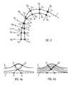
- intersection point on the template 7 are chosen as handle 11 1 - 11 8 (squares) and the respective point on the rest tooth 1 as respective target 12 1 - 12 8 (circles). If an intersection of a line 10 1 - 10 8 with the tooth template 7 is observed in both positive and negative normal directions, the intersection point with the smaller distance to the point the line going through of the surface of the rest tooth 1 is chosen.
- the open circles 12 2 - 12 8 correspond to targets on the outer surface 3 of the rest tooth 1 having respective handles on the tooth template 7 indicated by the open squares 11 2 - 11 8 .
- the filled circle 12 1 corresponds to a point on the preparation margin 4 and the respective handle on the tooth template 7 is indicated by the filled square 11 1 .
- the deformation of the tooth template 7 is performed as an iterative process.
- the deformation of the tooth template 7, according to the targets 12 1 - 12 8 is performed in the unprepared region of the rest tooth 1 and at the preparation margin 4.
- the algorithm starts at points on the surface of the rest tooth 1 and the algorithm uses these points as targets 12 1 - 12 8 , it is not required to make a determination after each iteration step whether a point of the tooth template 7 which is a handle for the next iteration step lies above the prepared or the unprepared region of the rest tooth 1 or above the preparation margin 4.
- the algorithm is considered to deform the tooth template 7 by pulling the tooth template 7 towards the rest tooth 1 and as the location of the targets 12 1 - 12 8 on the rest tooth 1 is known, it is also known that a handle on the tooth template 7 will be deformed towards this location.
- the deformation vectors are determined starting from vertices on the model tooth and thus after each iteration step a new classification of the hits on the surface of the rest tooth has to be performed.
- Handle weights increase form low values to bigger values successively during the iterative process.
- Figures 4a and 4b illustratively show the result when performing the deformation in a single step and when performing the deformation using an iterative process, respectively.
- self-intersections are produced resulting in a deformed surface that is not usable for a dental restoration.
- the shape preservation characteristic of the Laplacian surface deformation is predominant and self-intersection is avoided.
- the deformed tooth template 7 is adjusted to fit the outer surface 3.
- the new deformed shape of the tooth template has to be calculated. This is achieved by solving an optimization problem, wherein a global deformation energy E may be constructed that measures how much a deformed triangle mesh with vertex coordinates P1 ',..., Pn ' differs from its initial rest pose with vertex coordinates p 1 , ..., p n .
- the deformation energy E integrates locally defined changes of the shape.
- L is the matrix form of the Laplacian operator
- C encapsulates the barycentric coordinates
- ⁇ is a vector with the x, y or z coordinates of Laplacian ⁇ i
- h is a vector containing the respective handle coordinates
- p' is the vector with the deformed vertex coordinates.
- the deformed tooth template can be reconstructed by a minimization in the linear least square sense.
- E p ⁇ p ⁇ T ⁇ L T ⁇ ML + C T ⁇ WC ⁇ p ⁇ - 2 ⁇ p ⁇ T ⁇ L T ⁇ M ⁇ + C T ⁇ Wh + ⁇ T ⁇ M ⁇ + h T ⁇ Wh .
- globalw g , I , p i g ⁇ i I p , wherein g ⁇ 1 is a global weighting factor, I ⁇ 1 is the number of iteration steps, i ⁇ 1 is the current iteration step and the power p ⁇ 1 determines the shape of the function.
- a tooth template 7 exists that has been deformed such that it describes the unprepared regions of the rest tooth 1.
- This part of the tooth template 7 that lies inside the preparation margin 4 describes the surface of the dental restoration to be designed, wherein this surface represents the surface of the dental restoration that will not be hidden by the rest tooth after attaching the dental restoration to the rest tooth 1.
- This surface may be e.g. a part of the chewing surface of a molar.
- the part of the tooth template 7 inside the preparation margin is relevant.
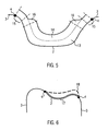
- the surface of the dental restoration describing the lower surface 2 is adapted by adding a cement gap 13 and a spacer gap 14, wherein a at some distance 15 from the preparation margin 4 a spacer transition 16 may exist.
- a minimal surface 17, as shown in figure 6 is constructed and every vertex of the deformed tooth template 18 is required to lie above this minimal surface 17.
- the minimal surface 17 is constructed by an offset on the rest tooth 1 and the mesh of the cavity to be provided with the dental restoration.
- rays i.e. lines
- a vertex is below the minimum wall thickness if the ray belonging to said vertex intersects a mesh triangle of the minimal surface and the difference between the normal direction of the vertex and the normal direction of the triangle is less than ⁇ / 2 .
- a respective handle is selected and the intersection point on the minimum surface 17 is selected as target.
- Handle weights are set in the same manner as for the deformation process of the tooth template 7, but the distance weighting is described independent from the current iteration as no general positioning is required.
- the deformation is applied to the boundary of the deformed tooth template 18 while fixing handles in the interior using large handle weights.
- the boundary is fixed and the interior is adjusted to the minimal surface 17.
- the thickening near the preparation margin 4 has different forms.
- the transition forms almost a rectangular angle, then almost no or none thickening can be observed and a flat and smooth transition between the corrected, deformed tooth template (i.e. the deformed tooth template 18 that has been corrected taking into account a minimal thickness) and the unprepared part of the rest tooth 1 is provided.
- the transition has an angle smaller than 90°, then a thickening is provided ensuring that the dental restoration will have a sufficient thickness also near the preparation margin.
- Another possibility for defining a minimal surface 17 is to apply an offset along the normal direction of each vertex of the lower surface 2 (wherein preferably the cement gap 13 and/or spacer gap 14 has already be added to the lower surface 2).
- Such an offset has a predefined value over the whole range of the lower surface 2 or the offset has smaller values near the preparation margin 4 and larger values at some predefined distance from the preparation margin 4 or vice versa.
- an average of several normal directions of several vertices are determined and then an offset is applied to this averaged normal direction.
Landscapes
- Health & Medical Sciences (AREA)
- Oral & Maxillofacial Surgery (AREA)
- Dentistry (AREA)
- Epidemiology (AREA)
- Life Sciences & Earth Sciences (AREA)
- Animal Behavior & Ethology (AREA)
- General Health & Medical Sciences (AREA)
- Public Health (AREA)
- Veterinary Medicine (AREA)
- Dental Tools And Instruments Or Auxiliary Dental Instruments (AREA)
Claims (13)
- Computerimplementiertes Verfahren zum digitalen Entwerfen eines Zahnersatzes für einen Restzahn (1), wobei der Restzahn (1) durch Daten des Restzahns (1) beschrieben wird, wobei die Daten des Restzahns (1) durch Scannen eines Zahnmodells des Restzahns (1) oder durch direktes Scannen eines Patientenrestzahns erhalten werden, und wobei eine Zahnvorlage (7) durch Daten der Zahnvorlage (7) beschrieben wird, wobei die Zahnvorlage (7) eine digitale Darstellung eines generischen Zahns darstellt, wobei das Verfahren den Schritt umfasst:- automatisches Verformen der Zahnvorlage (7) mittels Laplaceoberflächenverformung, so dass ein präparierter Teil des Restzahns (1) durch einen Anteil der Zahnvorlage (7) bedeckt wird;
dadurch gekennzeichnet, dass
die Laplaceoberflächenverformung umfasst:- automatisches Erzeugen einer Linie, die durch einen Punkt auf der Oberfläche des Restzahns (1) oder der Zahnvorlage (7) geht und die entlang der Normalenrichtung bei besagtem Punkt ausgerichtet ist, welche die Normalenrichtung zu der Tangentenebene bei besagtem Punkt auf der Oberfläche des Restzahns (1) oder der Zahnvorlage (7) ist;- wenn die Linie die Zahnvorlage (7) und die Oberfläche des Restzahns (1) schneidet, automatisches Auswählen des Schnittpunkts der Linie mit der Zahnvorlage (7) als Handle (11) und des Schnittpunkts mit der Oberfläche des Restzahns (1) als Target (12); und- automatisches Verformen der Zahnvorlage (7). - Das computerimplementierte Verfahren nach Anspruch 1, wobei der Punkt auf der Oberfläche der Zahnvorlage (7) ein Eckpunkt oder ein Punkt innerhalb eines Dreiecks eines Vielecknetzes ist, das die Oberfläche der Zahnvorlage beschreibt und wobei die Normalenrichtung bei einem Eckpunkt definiert ist durch den Mittelwert von Normalenrichtungen von Dreiecken, die besagten Eckpunkt als eine Ecke haben oder von Dreiecken, die innerhalb einer Kugel oder eines Volumens einer vordefinierten Größe um besagten Eckpunkt liegen.
- Das computerimplementierte Verfahren nach Ansprüchen 1 oder 2, wobei die Daten der Zahnvorlage eine Vielecknetz umfassen, das die Oberfläche der Zahnvorlage beschreibt und wobei die Laplaceoberflächenverformung weiter ein Verwenden eines Handles (11) umfasst, das innerhalb eines Vielecks des Netzes der Zahnvorlage (7) liegt.
- Das computerimplementierte Verfahren nach Ansprüchen 1 bis 3, wobei das automatische Verformen der Zahnvorlage bei der Laplaceoberflächenverformung weiter ein Bewegen des Handles (11) auf das Target (12) zu umfasst.
- Das computerimplementierte Verfahren nach Ansprüchen 1 bis 4, wobei die Laplaceoberflächenverformung weiter ein automatisches iteratives Durchführen der Verformung der Zahnvorlage (7) umfasst.
- Das computerimplementierte Verfahren nach Anspruch 5, wobei das automatische iterative Durchführen der Verformung der Zahnvorlage (7) ein Handlegewicht verwendet, das zunimmt, wenn der Interationsprozess voranschreitet, vorzugsweise beginnend mit einem vordefinierten minimalen Handlegewicht.
- Das computerimplementierte Verfahren nach Anspruch 6, wobei das Verfahren weiter den Schritt umfasst von einem Definieren des Handlegewichts für die Verformung als ein Produkt, das ein globales Gewicht, das mit jedem Iterationsschritt zunimmt und eines oder beides von:- einem Abstandsgewicht, das mit ansteigenden Abständen zwischen dem Target (12) und dem Handle (11) abnimmt, wobei die Abhängigkeit des Abstandsgewichts von dem Abstand mit jedem Iterationsschritt variieren kann; oder- einem Winkelgewicht, das von dem Winkel zwischen der Normalenrichtung des Targets (12) und der Normalenrichtung des Handles (11) abhängt, umfasst.
- Das computerimplementierte Verfahren nach Ansprüchen 5 bis 7, wobei das Verfahren weiter den Schritt von einem automatischen Extrahieren eines Anteils der Zahnvorlage durch digitales Schneiden der verformten Zahnvorlage entlang einer Präparationsgrenze (4) umfasst.
- Das computerimplementierte Verfahren nach Anspruch 8, wobei das Verfahren weiter den Schritt umfasst von einem automatischen Kombinieren von Daten, die den ausgeschnittenen verformten Zahnvorlagenanteil beschreiben mit Daten, die die Oberfläche des Restzahns (1) innerhalb der Präparationsgrenze (4) darstellen, um Daten eines dreidimensionalen Entwurfs des Zahnersatzes bereitzustellen.
- Das computerimplementierte Verfahren nach Anspruch 9, wobei das Verfahren weiter den Schritt umfasst von einem automatischen Hinzufügen eines Zementspalts (13) und/oder eines Abstandsspalts (14) zu den Daten, die die Oberfläche des Zahnersatzes darstellen, die in Kontakt mit dem Restzahn (1) wäre, die sogenannte untere Oberfläche (2).
- Das computerimplementierte Verfahren nach Anspruch 10, wobei das Hinzufügen durchgeführt wird durch automatisches Anwenden eines Offsets entlang der Normalenrichtungen von Punkten, wie zum Beispiel Eckpunkten, der unteren Oberfläche (2), wobei die Normalenrichtungen vorzugsweise über eine definierte Fläche um jeden Punkt gemittelt sind.
- Das computerimplementierte Verfahren nach Ansprüchen 1 oder 2, wobei das Verfahren weiter den Schritt umfasst von einem automatischen Positionieren der Zahnvorlage (7) in Hinblick auf den Restzahn (1) durch Ausrichten des Restzahns (1) und der Zahnvorlage (7), um in bukkaler Richtung und in okklusaler Richtung übereinzustimmen.
- Das computerimplementierte Verfahren nach Anspruch 12, wobei das Verfahren weiter den Schritt umfasst von einem automatischen Skalieren der Zahnvorlage (7) in bukkaler Richtung und in Richtung der mesial-distalen Achse entsprechend der horizontalen Ausdehnung der präparierten Oberfläche des Restzahns (1), wobei vorzugsweise kein Skalieren in okklusaler Richtung vorgenommen wird.
Priority Applications (9)
| Application Number | Priority Date | Filing Date | Title |
|---|---|---|---|
| EP10009047A EP2422741B1 (de) | 2010-08-31 | 2010-08-31 | Computerimplementiertes Verfahren für die digitale Planung eines Zahnersatzes |
| EP12001137.4A EP2468212B1 (de) | 2010-08-31 | 2011-03-18 | Computerimplementiertes Verfahren für die digitale Planung eines Zahnersatzes |
| EP11002250.6A EP2422742B1 (de) | 2010-08-31 | 2011-03-18 | Computerimplementiertes Verfahren für die digitale Planung eines Zahnersatzes |
| US13/812,061 US9396291B2 (en) | 2010-08-31 | 2011-08-23 | Computer-implemented method for digitally designing a dental restoration and a computer-readable medium |
| US13/812,020 US9286417B2 (en) | 2010-08-31 | 2011-08-23 | Computer-implemented method for digitally designing a dental restoration and a computer-readable medium |
| US13/812,093 US9330205B2 (en) | 2010-08-31 | 2011-08-23 | Computer-implemented method for digitally designing a dental restoration and a computer-readable medium |
| PCT/EP2011/004230 WO2012028270A2 (en) | 2010-08-31 | 2011-08-23 | Computer-implemented method for digitally designing a dental restoration and a computer-readable medium |
| PCT/EP2011/004232 WO2012028272A1 (en) | 2010-08-31 | 2011-08-23 | Computer-implemented method for digitally designing a dental restoration and a computer-readable medium |
| PCT/EP2011/004231 WO2012028271A1 (en) | 2010-08-31 | 2011-08-23 | Computer-implemented method for digitally designing a dental restoration and a computer-readable medium |
Applications Claiming Priority (1)
| Application Number | Priority Date | Filing Date | Title |
|---|---|---|---|
| EP10009047A EP2422741B1 (de) | 2010-08-31 | 2010-08-31 | Computerimplementiertes Verfahren für die digitale Planung eines Zahnersatzes |
Publications (2)
| Publication Number | Publication Date |
|---|---|
| EP2422741A1 EP2422741A1 (de) | 2012-02-29 |
| EP2422741B1 true EP2422741B1 (de) | 2013-01-23 |
Family
ID=43416519
Family Applications (1)
| Application Number | Title | Priority Date | Filing Date |
|---|---|---|---|
| EP10009047A Active EP2422741B1 (de) | 2010-08-31 | 2010-08-31 | Computerimplementiertes Verfahren für die digitale Planung eines Zahnersatzes |
Country Status (1)
| Country | Link |
|---|---|
| EP (1) | EP2422741B1 (de) |
Families Citing this family (5)
| Publication number | Priority date | Publication date | Assignee | Title |
|---|---|---|---|---|
| CN104599327B (zh) * | 2015-01-30 | 2017-12-26 | 杭州一牙数字口腔有限公司 | 一种牙颌黑三角的自动检测和修复方法 |
| DE102017203475A1 (de) * | 2017-03-03 | 2018-09-06 | Sirona Dental Systems Gmbh | Verfahren zur Konstruktion einer Restauration |
| CN109872394B (zh) * | 2019-01-10 | 2021-04-27 | 重庆大学 | 基于最小二乘支持向量机的狭长三角形网格优化方法 |
| CN116507296B (zh) * | 2020-10-28 | 2026-02-24 | 株式会社美迪特 | 处理三维口腔模型的方法和装置以及计算机可读记录介质 |
| CN120000354B (zh) * | 2025-04-16 | 2025-08-08 | 先临三维科技股份有限公司 | 牙冠咬合面调整方法、装置、电子设备及存储介质 |
Family Cites Families (1)
| Publication number | Priority date | Publication date | Assignee | Title |
|---|---|---|---|---|
| US8108189B2 (en) * | 2008-03-25 | 2012-01-31 | Align Technologies, Inc. | Reconstruction of non-visible part of tooth |
-
2010
- 2010-08-31 EP EP10009047A patent/EP2422741B1/de active Active
Also Published As
| Publication number | Publication date |
|---|---|
| EP2422741A1 (de) | 2012-02-29 |
Similar Documents
| Publication | Publication Date | Title |
|---|---|---|
| EP2422742B1 (de) | Computerimplementiertes Verfahren für die digitale Planung eines Zahnersatzes | |
| US11803669B2 (en) | Systems for generating digital models of patient teeth | |
| US20060172263A1 (en) | Mill blank | |
| US10335251B2 (en) | Orthodontic digital setups | |
| US9283061B2 (en) | Method and analysis system for the geometrical analysis of scan data from oral structures | |
| US7747418B2 (en) | Computer aided dental bar design | |
| US20100167243A1 (en) | System and method for automatic construction of realistic looking tooth roots | |
| US20060183082A1 (en) | Method and computer system for creating a dental restoration model | |
| EP2422741A1 (de) | Computerimplementiertes Verfahren für die digitale Planung eines Zahnersatzes und computerlesbares Medium | |
| CN101944156A (zh) | 一种单颗牙齿包容体的确定方法 | |
| US10456225B2 (en) | Method for clearing of virtual representations of objects | |
| EP2422740B1 (de) | Computerimplementiertes Verfahren für die digitale Planung eines Zahnersatzes und computerlesbares Medium | |
| EP3560455B1 (de) | Entwurf eines virtuellen präparats und eines virtuellen zahnfleischs | |
| Yau et al. | Computer-aided framework design for digital dentistry | |
| CN120513461A (zh) | 用于生成全齿几何网格的系统和方法 | |
| EP2525327A1 (de) | Computerimplementiertes Verfahren zur digitalen Verkürzung einer Kappe einer Zahnbrücke und computerlesbares Medium |
Legal Events
| Date | Code | Title | Description |
|---|---|---|---|
| AK | Designated contracting states |
Kind code of ref document: A1 Designated state(s): AL AT BE BG CH CY CZ DE DK EE ES FI FR GB GR HR HU IE IS IT LI LT LU LV MC MK MT NL NO PL PT RO SE SI SK SM TR |
|
| AX | Request for extension of the european patent |
Extension state: BA ME RS |
|
| PUAI | Public reference made under article 153(3) epc to a published international application that has entered the european phase |
Free format text: ORIGINAL CODE: 0009012 |
|
| 17P | Request for examination filed |
Effective date: 20120202 |
|
| 17Q | First examination report despatched |
Effective date: 20120308 |
|
| GRAP | Despatch of communication of intention to grant a patent |
Free format text: ORIGINAL CODE: EPIDOSNIGR1 |
|
| GRAS | Grant fee paid |
Free format text: ORIGINAL CODE: EPIDOSNIGR3 |
|
| GRAA | (expected) grant |
Free format text: ORIGINAL CODE: 0009210 |
|
| AK | Designated contracting states |
Kind code of ref document: B1 Designated state(s): AL AT BE BG CH CY CZ DE DK EE ES FI FR GB GR HR HU IE IS IT LI LT LU LV MC MK MT NL NO PL PT RO SE SI SK SM TR |
|
| REG | Reference to a national code |
Ref country code: GB Ref legal event code: FG4D |
|
| REG | Reference to a national code |
Ref country code: CH Ref legal event code: EP |
|
| REG | Reference to a national code |
Ref country code: AT Ref legal event code: REF Ref document number: 594533 Country of ref document: AT Kind code of ref document: T Effective date: 20130215 Ref country code: CH Ref legal event code: EP |
|
| REG | Reference to a national code |
Ref country code: IE Ref legal event code: FG4D |
|
| REG | Reference to a national code |
Ref country code: DE Ref legal event code: R096 Ref document number: 602010004751 Country of ref document: DE Effective date: 20130321 |
|
| REG | Reference to a national code |
Ref country code: AT Ref legal event code: MK05 Ref document number: 594533 Country of ref document: AT Kind code of ref document: T Effective date: 20130123 |
|
| REG | Reference to a national code |
Ref country code: LT Ref legal event code: MG4D |
|
| REG | Reference to a national code |
Ref country code: NL Ref legal event code: VDEP Effective date: 20130123 |
|
| PG25 | Lapsed in a contracting state [announced via postgrant information from national office to epo] |
Ref country code: ES Free format text: LAPSE BECAUSE OF FAILURE TO SUBMIT A TRANSLATION OF THE DESCRIPTION OR TO PAY THE FEE WITHIN THE PRESCRIBED TIME-LIMIT Effective date: 20130504 Ref country code: AT Free format text: LAPSE BECAUSE OF FAILURE TO SUBMIT A TRANSLATION OF THE DESCRIPTION OR TO PAY THE FEE WITHIN THE PRESCRIBED TIME-LIMIT Effective date: 20130123 Ref country code: IS Free format text: LAPSE BECAUSE OF FAILURE TO SUBMIT A TRANSLATION OF THE DESCRIPTION OR TO PAY THE FEE WITHIN THE PRESCRIBED TIME-LIMIT Effective date: 20130523 Ref country code: SE Free format text: LAPSE BECAUSE OF FAILURE TO SUBMIT A TRANSLATION OF THE DESCRIPTION OR TO PAY THE FEE WITHIN THE PRESCRIBED TIME-LIMIT Effective date: 20130123 Ref country code: BE Free format text: LAPSE BECAUSE OF FAILURE TO SUBMIT A TRANSLATION OF THE DESCRIPTION OR TO PAY THE FEE WITHIN THE PRESCRIBED TIME-LIMIT Effective date: 20130123 Ref country code: NO Free format text: LAPSE BECAUSE OF FAILURE TO SUBMIT A TRANSLATION OF THE DESCRIPTION OR TO PAY THE FEE WITHIN THE PRESCRIBED TIME-LIMIT Effective date: 20130423 Ref country code: LT Free format text: LAPSE BECAUSE OF FAILURE TO SUBMIT A TRANSLATION OF THE DESCRIPTION OR TO PAY THE FEE WITHIN THE PRESCRIBED TIME-LIMIT Effective date: 20130123 Ref country code: BG Free format text: LAPSE BECAUSE OF FAILURE TO SUBMIT A TRANSLATION OF THE DESCRIPTION OR TO PAY THE FEE WITHIN THE PRESCRIBED TIME-LIMIT Effective date: 20130423 |
|
| PG25 | Lapsed in a contracting state [announced via postgrant information from national office to epo] |
Ref country code: GR Free format text: LAPSE BECAUSE OF FAILURE TO SUBMIT A TRANSLATION OF THE DESCRIPTION OR TO PAY THE FEE WITHIN THE PRESCRIBED TIME-LIMIT Effective date: 20130424 Ref country code: SI Free format text: LAPSE BECAUSE OF FAILURE TO SUBMIT A TRANSLATION OF THE DESCRIPTION OR TO PAY THE FEE WITHIN THE PRESCRIBED TIME-LIMIT Effective date: 20130123 Ref country code: PL Free format text: LAPSE BECAUSE OF FAILURE TO SUBMIT A TRANSLATION OF THE DESCRIPTION OR TO PAY THE FEE WITHIN THE PRESCRIBED TIME-LIMIT Effective date: 20130123 Ref country code: LV Free format text: LAPSE BECAUSE OF FAILURE TO SUBMIT A TRANSLATION OF THE DESCRIPTION OR TO PAY THE FEE WITHIN THE PRESCRIBED TIME-LIMIT Effective date: 20130123 Ref country code: FI Free format text: LAPSE BECAUSE OF FAILURE TO SUBMIT A TRANSLATION OF THE DESCRIPTION OR TO PAY THE FEE WITHIN THE PRESCRIBED TIME-LIMIT Effective date: 20130123 Ref country code: NL Free format text: LAPSE BECAUSE OF FAILURE TO SUBMIT A TRANSLATION OF THE DESCRIPTION OR TO PAY THE FEE WITHIN THE PRESCRIBED TIME-LIMIT Effective date: 20130123 Ref country code: PT Free format text: LAPSE BECAUSE OF FAILURE TO SUBMIT A TRANSLATION OF THE DESCRIPTION OR TO PAY THE FEE WITHIN THE PRESCRIBED TIME-LIMIT Effective date: 20130523 |
|
| PG25 | Lapsed in a contracting state [announced via postgrant information from national office to epo] |
Ref country code: HR Free format text: LAPSE BECAUSE OF FAILURE TO SUBMIT A TRANSLATION OF THE DESCRIPTION OR TO PAY THE FEE WITHIN THE PRESCRIBED TIME-LIMIT Effective date: 20130123 |
|
| PG25 | Lapsed in a contracting state [announced via postgrant information from national office to epo] |
Ref country code: CZ Free format text: LAPSE BECAUSE OF FAILURE TO SUBMIT A TRANSLATION OF THE DESCRIPTION OR TO PAY THE FEE WITHIN THE PRESCRIBED TIME-LIMIT Effective date: 20130123 Ref country code: SK Free format text: LAPSE BECAUSE OF FAILURE TO SUBMIT A TRANSLATION OF THE DESCRIPTION OR TO PAY THE FEE WITHIN THE PRESCRIBED TIME-LIMIT Effective date: 20130123 Ref country code: EE Free format text: LAPSE BECAUSE OF FAILURE TO SUBMIT A TRANSLATION OF THE DESCRIPTION OR TO PAY THE FEE WITHIN THE PRESCRIBED TIME-LIMIT Effective date: 20130123 Ref country code: RO Free format text: LAPSE BECAUSE OF FAILURE TO SUBMIT A TRANSLATION OF THE DESCRIPTION OR TO PAY THE FEE WITHIN THE PRESCRIBED TIME-LIMIT Effective date: 20130123 Ref country code: DK Free format text: LAPSE BECAUSE OF FAILURE TO SUBMIT A TRANSLATION OF THE DESCRIPTION OR TO PAY THE FEE WITHIN THE PRESCRIBED TIME-LIMIT Effective date: 20130123 |
|
| PG25 | Lapsed in a contracting state [announced via postgrant information from national office to epo] |
Ref country code: CY Free format text: LAPSE BECAUSE OF FAILURE TO SUBMIT A TRANSLATION OF THE DESCRIPTION OR TO PAY THE FEE WITHIN THE PRESCRIBED TIME-LIMIT Effective date: 20130123 |
|
| PLBE | No opposition filed within time limit |
Free format text: ORIGINAL CODE: 0009261 |
|
| STAA | Information on the status of an ep patent application or granted ep patent |
Free format text: STATUS: NO OPPOSITION FILED WITHIN TIME LIMIT |
|
| PG25 | Lapsed in a contracting state [announced via postgrant information from national office to epo] |
Ref country code: IT Free format text: LAPSE BECAUSE OF FAILURE TO SUBMIT A TRANSLATION OF THE DESCRIPTION OR TO PAY THE FEE WITHIN THE PRESCRIBED TIME-LIMIT Effective date: 20130123 |
|
| 26N | No opposition filed |
Effective date: 20131024 |
|
| REG | Reference to a national code |
Ref country code: DE Ref legal event code: R097 Ref document number: 602010004751 Country of ref document: DE Effective date: 20131024 |
|
| PG25 | Lapsed in a contracting state [announced via postgrant information from national office to epo] |
Ref country code: MC Free format text: LAPSE BECAUSE OF FAILURE TO SUBMIT A TRANSLATION OF THE DESCRIPTION OR TO PAY THE FEE WITHIN THE PRESCRIBED TIME-LIMIT Effective date: 20130123 |
|
| REG | Reference to a national code |
Ref country code: IE Ref legal event code: MM4A |
|
| REG | Reference to a national code |
Ref country code: FR Ref legal event code: ST Effective date: 20140430 |
|
| PG25 | Lapsed in a contracting state [announced via postgrant information from national office to epo] |
Ref country code: IE Free format text: LAPSE BECAUSE OF NON-PAYMENT OF DUE FEES Effective date: 20130831 |
|
| PG25 | Lapsed in a contracting state [announced via postgrant information from national office to epo] |
Ref country code: FR Free format text: LAPSE BECAUSE OF NON-PAYMENT OF DUE FEES Effective date: 20130902 |
|
| PG25 | Lapsed in a contracting state [announced via postgrant information from national office to epo] |
Ref country code: SM Free format text: LAPSE BECAUSE OF FAILURE TO SUBMIT A TRANSLATION OF THE DESCRIPTION OR TO PAY THE FEE WITHIN THE PRESCRIBED TIME-LIMIT Effective date: 20130123 |
|
| PG25 | Lapsed in a contracting state [announced via postgrant information from national office to epo] |
Ref country code: MT Free format text: LAPSE BECAUSE OF FAILURE TO SUBMIT A TRANSLATION OF THE DESCRIPTION OR TO PAY THE FEE WITHIN THE PRESCRIBED TIME-LIMIT Effective date: 20130123 Ref country code: TR Free format text: LAPSE BECAUSE OF FAILURE TO SUBMIT A TRANSLATION OF THE DESCRIPTION OR TO PAY THE FEE WITHIN THE PRESCRIBED TIME-LIMIT Effective date: 20130123 |
|
| PG25 | Lapsed in a contracting state [announced via postgrant information from national office to epo] |
Ref country code: MK Free format text: LAPSE BECAUSE OF FAILURE TO SUBMIT A TRANSLATION OF THE DESCRIPTION OR TO PAY THE FEE WITHIN THE PRESCRIBED TIME-LIMIT Effective date: 20130123 Ref country code: HU Free format text: LAPSE BECAUSE OF FAILURE TO SUBMIT A TRANSLATION OF THE DESCRIPTION OR TO PAY THE FEE WITHIN THE PRESCRIBED TIME-LIMIT; INVALID AB INITIO Effective date: 20100831 Ref country code: LU Free format text: LAPSE BECAUSE OF NON-PAYMENT OF DUE FEES Effective date: 20130831 |
|
| PG25 | Lapsed in a contracting state [announced via postgrant information from national office to epo] |
Ref country code: AL Free format text: LAPSE BECAUSE OF FAILURE TO SUBMIT A TRANSLATION OF THE DESCRIPTION OR TO PAY THE FEE WITHIN THE PRESCRIBED TIME-LIMIT Effective date: 20130123 |
|
| PGFP | Annual fee paid to national office [announced via postgrant information from national office to epo] |
Ref country code: DE Payment date: 20250820 Year of fee payment: 16 |
|
| PGFP | Annual fee paid to national office [announced via postgrant information from national office to epo] |
Ref country code: GB Payment date: 20250820 Year of fee payment: 16 |
|
| PGFP | Annual fee paid to national office [announced via postgrant information from national office to epo] |
Ref country code: CH Payment date: 20250901 Year of fee payment: 16 |