EP2422860A2 - Procédé de condensation et condensateur - Google Patents
Procédé de condensation et condensateur Download PDFInfo
- Publication number
- EP2422860A2 EP2422860A2 EP11008452A EP11008452A EP2422860A2 EP 2422860 A2 EP2422860 A2 EP 2422860A2 EP 11008452 A EP11008452 A EP 11008452A EP 11008452 A EP11008452 A EP 11008452A EP 2422860 A2 EP2422860 A2 EP 2422860A2
- Authority
- EP
- European Patent Office
- Prior art keywords
- gas
- condenser
- condensing
- liquid
- coolant
- Prior art date
- Legal status (The legal status is an assumption and is not a legal conclusion. Google has not performed a legal analysis and makes no representation as to the accuracy of the status listed.)
- Withdrawn
Links
- 238000000034 method Methods 0.000 title claims description 48
- 230000008569 process Effects 0.000 title description 41
- 238000009833 condensation Methods 0.000 title description 27
- 230000005494 condensation Effects 0.000 title description 27
- 239000007789 gas Substances 0.000 claims abstract description 220
- 239000007788 liquid Substances 0.000 claims abstract description 29
- 239000002826 coolant Substances 0.000 claims description 52
- 238000001816 cooling Methods 0.000 claims description 41
- 238000011144 upstream manufacturing Methods 0.000 claims description 6
- 238000007710 freezing Methods 0.000 claims description 3
- 230000008014 freezing Effects 0.000 claims description 3
- 238000005086 pumping Methods 0.000 claims description 2
- 238000012544 monitoring process Methods 0.000 claims 1
- 239000000203 mixture Substances 0.000 abstract description 39
- 230000000694 effects Effects 0.000 abstract description 23
- 238000013461 design Methods 0.000 description 35
- XLYOFNOQVPJJNP-UHFFFAOYSA-N water Substances O XLYOFNOQVPJJNP-UHFFFAOYSA-N 0.000 description 32
- 238000012546 transfer Methods 0.000 description 28
- 241000196324 Embryophyta Species 0.000 description 22
- 230000001965 increasing effect Effects 0.000 description 13
- 239000012530 fluid Substances 0.000 description 10
- 230000009467 reduction Effects 0.000 description 10
- 238000000605 extraction Methods 0.000 description 7
- 238000010438 heat treatment Methods 0.000 description 7
- 230000008901 benefit Effects 0.000 description 6
- 238000005259 measurement Methods 0.000 description 5
- 238000013459 approach Methods 0.000 description 4
- 230000015572 biosynthetic process Effects 0.000 description 4
- 238000009835 boiling Methods 0.000 description 4
- 239000000498 cooling water Substances 0.000 description 4
- 238000005755 formation reaction Methods 0.000 description 4
- 230000002411 adverse Effects 0.000 description 3
- 238000004364 calculation method Methods 0.000 description 3
- 238000010276 construction Methods 0.000 description 3
- 230000005611 electricity Effects 0.000 description 3
- 238000012986 modification Methods 0.000 description 3
- 230000004048 modification Effects 0.000 description 3
- 238000010248 power generation Methods 0.000 description 3
- 230000015556 catabolic process Effects 0.000 description 2
- 230000003247 decreasing effect Effects 0.000 description 2
- 238000006731 degradation reaction Methods 0.000 description 2
- 238000009792 diffusion process Methods 0.000 description 2
- 230000002708 enhancing effect Effects 0.000 description 2
- 238000010926 purge Methods 0.000 description 2
- 229920006395 saturated elastomer Polymers 0.000 description 2
- 238000004659 sterilization and disinfection Methods 0.000 description 2
- 206010037660 Pyrexia Diseases 0.000 description 1
- 238000009825 accumulation Methods 0.000 description 1
- 230000003466 anti-cipated effect Effects 0.000 description 1
- 238000000429 assembly Methods 0.000 description 1
- 230000004323 axial length Effects 0.000 description 1
- 230000009286 beneficial effect Effects 0.000 description 1
- 230000008859 change Effects 0.000 description 1
- 238000003889 chemical engineering Methods 0.000 description 1
- 238000004891 communication Methods 0.000 description 1
- 239000000470 constituent Substances 0.000 description 1
- 230000008602 contraction Effects 0.000 description 1
- 239000000110 cooling liquid Substances 0.000 description 1
- 230000000593 degrading effect Effects 0.000 description 1
- 230000003111 delayed effect Effects 0.000 description 1
- 230000009977 dual effect Effects 0.000 description 1
- 230000008030 elimination Effects 0.000 description 1
- 238000003379 elimination reaction Methods 0.000 description 1
- 238000002474 experimental method Methods 0.000 description 1
- 230000002349 favourable effect Effects 0.000 description 1
- 230000004907 flux Effects 0.000 description 1
- 230000005484 gravity Effects 0.000 description 1
- 238000002347 injection Methods 0.000 description 1
- 239000007924 injection Substances 0.000 description 1
- 238000007689 inspection Methods 0.000 description 1
- 230000007774 longterm Effects 0.000 description 1
- 238000012423 maintenance Methods 0.000 description 1
- 238000004519 manufacturing process Methods 0.000 description 1
- 239000002574 poison Substances 0.000 description 1
- 231100000614 poison Toxicity 0.000 description 1
- 238000003303 reheating Methods 0.000 description 1
- 238000011160 research Methods 0.000 description 1
- 238000009420 retrofitting Methods 0.000 description 1
- 238000007788 roughening Methods 0.000 description 1
- 230000035945 sensitivity Effects 0.000 description 1
- 239000007921 spray Substances 0.000 description 1
- 239000000126 substance Substances 0.000 description 1
- 239000002699 waste material Substances 0.000 description 1
Images


Classifications
-
- B—PERFORMING OPERATIONS; TRANSPORTING
- B01—PHYSICAL OR CHEMICAL PROCESSES OR APPARATUS IN GENERAL
- B01D—SEPARATION
- B01D5/00—Condensation of vapours; Recovering volatile solvents by condensation
- B01D5/0078—Condensation of vapours; Recovering volatile solvents by condensation characterised by auxiliary systems or arrangements
- B01D5/0093—Removing and treatment of non condensable gases
-
- B—PERFORMING OPERATIONS; TRANSPORTING
- B01—PHYSICAL OR CHEMICAL PROCESSES OR APPARATUS IN GENERAL
- B01D—SEPARATION
- B01D5/00—Condensation of vapours; Recovering volatile solvents by condensation
- B01D5/0033—Other features
- B01D5/0036—Multiple-effect condensation; Fractional condensation
-
- B—PERFORMING OPERATIONS; TRANSPORTING
- B01—PHYSICAL OR CHEMICAL PROCESSES OR APPARATUS IN GENERAL
- B01D—SEPARATION
- B01D53/00—Separation of gases or vapours; Recovering vapours of volatile solvents from gases; Chemical or biological purification of waste gases, e.g. engine exhaust gases, smoke, fumes, flue gases, aerosols
- B01D53/002—Separation of gases or vapours; Recovering vapours of volatile solvents from gases; Chemical or biological purification of waste gases, e.g. engine exhaust gases, smoke, fumes, flue gases, aerosols by condensation
-
- B—PERFORMING OPERATIONS; TRANSPORTING
- B01—PHYSICAL OR CHEMICAL PROCESSES OR APPARATUS IN GENERAL
- B01D—SEPARATION
- B01D53/00—Separation of gases or vapours; Recovering vapours of volatile solvents from gases; Chemical or biological purification of waste gases, e.g. engine exhaust gases, smoke, fumes, flue gases, aerosols
- B01D53/26—Drying gases or vapours
- B01D53/265—Drying gases or vapours by refrigeration (condensation)
-
- Y—GENERAL TAGGING OF NEW TECHNOLOGICAL DEVELOPMENTS; GENERAL TAGGING OF CROSS-SECTIONAL TECHNOLOGIES SPANNING OVER SEVERAL SECTIONS OF THE IPC; TECHNICAL SUBJECTS COVERED BY FORMER USPC CROSS-REFERENCE ART COLLECTIONS [XRACs] AND DIGESTS
- Y10—TECHNICAL SUBJECTS COVERED BY FORMER USPC
- Y10S—TECHNICAL SUBJECTS COVERED BY FORMER USPC CROSS-REFERENCE ART COLLECTIONS [XRACs] AND DIGESTS
- Y10S165/00—Heat exchange
- Y10S165/184—Indirect-contact condenser
- Y10S165/205—Space for condensable vapor surrounds space for coolant
- Y10S165/207—Distinct outlets for separated condensate and gas
-
- Y—GENERAL TAGGING OF NEW TECHNOLOGICAL DEVELOPMENTS; GENERAL TAGGING OF CROSS-SECTIONAL TECHNOLOGIES SPANNING OVER SEVERAL SECTIONS OF THE IPC; TECHNICAL SUBJECTS COVERED BY FORMER USPC CROSS-REFERENCE ART COLLECTIONS [XRACs] AND DIGESTS
- Y10—TECHNICAL SUBJECTS COVERED BY FORMER USPC
- Y10S—TECHNICAL SUBJECTS COVERED BY FORMER USPC CROSS-REFERENCE ART COLLECTIONS [XRACs] AND DIGESTS
- Y10S55/00—Gas separation
- Y10S55/15—Cold traps
Definitions
- the present invention relates to condensers and methods for enhancing the efficiency of condensers.
- the invention is applicable to the condensation of a first gas that is mixed with at least one second gas having a lower boiling point than the first gas.
- the invention is applicable in particular to steam condensers of the type used in electric power generation, but is also applicable in any circumstances in which a gas is being condensed from a mixture of gases.
- the pressure of the gas mixture everywhere in the condenser is the sum of the local partial pressures of the steam and the air and that the flow distance through the boundary layer from the bulk gas to the condensate film is small, the total pressure at both sides of the boundary layer must be substantially the same.
- the steam At the surface of the condensed water film, the steam must be at saturation temperature. Given that the air partial pressure at the surface of the water has increased, the steam partial pressure there has reduced. Therefore the saturation temperature of the steam there is also reduced, and a temperature difference has developed across the boundary layer.
- the present invention is based on the theory discussed above and the realisation that the effect of non-condensing gases on condensation processes has been generally under-estimated, enabling surprising improvements in performance to be achieved by relatively modest modifications to current design thinking.
- the invention has as its object the delivery of such performance improvements.
- a method for removing non-condensing gas from a mixture of condensing and non-condensing gases in a condenser wherein gas is withdrawn from at least one location within the condenser, the location being selected to correspond to a region within the condenser in which the gas is at a temperature which is lower than the temperature of gas in other regions within the condenser.
- the present invention also provides a condenser for condensing gas in which gas is condensed to liquid on a heat exchanging surface, comprising means for withdrawing gas from within the condenser to remove non-condensing gas, the gas withdrawing means being positioned to withdraw gas from at least one location in which the gas temperature is lower than in other regions within the condenser.
- the above first aspect of the present invention relies upon the realisation that non-condensing gases tend to accumulate in regions of a condenser which are relatively cold and therefore extracting gas from such regions results in a relatively efficient removal of non-condensing gases from the condenser.
- Gas may be extracted from adjacent an arrangement designed to produce a localised region of relatively cold gas.
- the arrangement may comprise a structure positioned so as to be cooled by condensing liquid.
- the structure may be in the form of a deflector located beneath the heat exchanging surface such that droplets of condensate fall onto and cool the deflector, gas being withdrawn from beneath the deflector.
- the deflector could be a simple cover extending over an upwardly extending gas withdrawal pipe, or an elongate gas withdrawal duct a lower side of which defines apertures through which gas is drawn into the duct.
- the deflector may be a simple elongate duct an underside of which defines an open channel, gas being withdrawn from one end of the duct.
- the elongate duct may extend beneath and preferably in parallel with a heat exchanger tube of the condenser.
- a shield may be located above the deflector to shield falling droplets of condensate from gas flowing through the condenser, thereby preventing the gas flow reheating falling droplets of condensate before they strike the deflector.
- a surface is defined within the condenser which is cooled by an external means, for example a flow of coolant in thermal contact with that surface.
- the surface could be cooled to a temperature lower than any other surface in the condenser.
- primary and secondary heat exchangers could be provided in series in the flow of gas to be condensed, the secondary heat exchanger being colder than the primary heat exchanger to deliver relatively cold condensate.
- Condensate withdrawn from the condenser could be passed through an auxiliary heat exchanger in the condenser to heat the condensate.
- the cooled surface may be defined by the surface of a pool of condensed liquid in thermal contact with a cooling device. The cooling device could for example be immersed in the condensate pool.
- the cooled surface could be defined by a wall of the condenser in thermal contact with a cooling device.
- the condenser wall could be defined by a cover plate which covers an aperture in the condenser, gas being withdrawn through the cover plate. The pressure and temperature of gas adjacent the cover plate could be monitored, the degree of cooling applied to the plate being controlled to maintain the temperature of the cover plate above the freezing point of the condensed liquid.
- a method for establishing favourable temperature differences between heat exchanger conduits within a condenser and a process fluid which flows through the condenser wherein coolant is pumped through an array of parallel heat exchanger conduits spaced apart in the direction of process fluid flow, at least two of the conduits being connected in series such that coolant flows sequentially through first and second conduits, the second conduit being located upstream of the first conduit in the direction of process fluid flow.
- the second aspect of the present invention also provides a condenser comprising an array of parallel heat exchanger conduits spaced apart in the direction of flow of a process fluid flow including a gas to be condensed, wherein at least two conduits that are spaced apart in the direction of fluid flow are connected in series such that coolant flows sequentially through first and second conduits, the second conduit being located upstream of the first conduit in the direction of process fluid flow.
- a first pair of first and second conduits may be connected in series, a second pair of first and second conduits may be connected in series, the direction of flow of coolant through the condenser being in one direction for the first conduit of the first pair and the second conduit of the second pair and in the opposite direction for the second conduit of the first pair and the first conduit of the second pair, the second conduit of the first pair being located upstream in the process flow of the first conduit of the second pair, and the second conduit of the second pair being located upstream in the process flow of the first conduit of the first pair.
- the parallel heat exchanger conduits may comprise parallel heat exchanger conduits.
- the parallel heat exchanger conduits may be defined by a staggered array of baffles.
- Each baffle extends transverse the direction of flow of the process fluid, with alternate baffles extending from opposite sides of the condenser.
- the condenser further comprises an array of process fluid tubes extending through the baffles for said flow of the process fluid.
- the third aspect of the present invention also provides a containment vessel intended to contain a release into the vessel of pressurised gas which will condense to a liquid at the temperatures and pressures assumed to prevail within the containment vessel, the containment vessel initially being filled with a gas or gases which will not condense at the temperatures and pressures assumed to prevail within the containment vessel, and the containment vessel including means for establishing in a lower portion of the vessel a body of the liquid of large surface area relative to the area of the vessel.
- the body of liquid may be established in a simple open tray arranged to collect condensing liquid.
- means may be provided for releasing a stored volume of the liquid into at least one open tray to form the body of liquid. Pressure within the containment vessel may be sensed, the stored volume of liquid being released in the event of the sensed pressure exceeding a predetermined threshold.
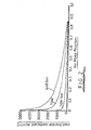
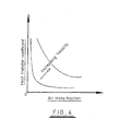
- Figure 4 presents information showing that an imposed gas velocity parallel to the condensing surface improves the heat transfer coefficient. But this is still expected to be significantly affected even at relatively high imposed velocities.
- the present invention makes it possible to reduce the air mass fraction immediately adjacent the cooling surfaces of heat exchangers and as a result to improve the efficiency of such devices. This makes it possible to reduce the size of a condenser required for a particular purpose as compared with conventionally designed condensers used for that purpose. Overall efficiency of plant is also increased. The result is potentially of very significant commercial importance.
- a vertical downward flow of a steam-air mixture passing a horizontal tube in which a coolant flows may be considered.
- the coolant at the hot end of the tube is 20°C, to a good approximation this will be the temperature of the water condensed at that location and therefore also the temperature of steam condensing at that location.
- the partial pressure of the steam at that location will be the saturation pressure given a temperature of 20°C, that is 23 mbars.
- the coolant at the cold end of the tube is 10°C, then by the same argument the partial pressure of steam at that location will be 12 mbars.
- the total pressure at both locations will be the same, the balance being made up by the partial pressure of air at each of the locations.
- extracting air from where its concentration is highest, that is adjacent the cold end of the tube reduces its partial pressure throughout the volume of the condenser. This improves the heat transfer process, resulting in the condensation of more steam and a reduction in the partial pressure of steam throughout the volume.
- the function of the condenser is to remove the latent heat from steam after it exits a turbine so that the steam is condensed to water.
- the coolant flowing through the tubes is usually water taken from a separate and dedicated system, whereas the process flow is steam.
- steam at an outlet of a turbine is at a subatmospheric pressure.
- the structure of the condenser is generally large, typically in excess of 6 metres high 15 metres long and many metres wide.
- condensers of this type define an enclosure housing a nest of tubes through which cooling water flows.
- the tubes are arranged in parallel so as to form a central open region about which the tubes are distributed.
- An air extraction duct is in communication with the central open region and air and steam within the central open region is simply pumped out of the condenser enclosure.
- the extract flow rate is one part in 10,000 of the steam flow.
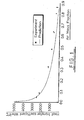
- the temperature of the condensate is, within measurement error, the saturation temperature of steam at 50 mbars.
- condensate forms at a lower temperature and that it is possible to reduce the vacuum after exit from the turbine.
- the set of parameters outlined above would be taken as indicating an excellent condenser design, as both the vacuum is in line with conventional expectations and the condensate has not been cooled to an unnecessarily low temperature.
- the air mass fraction within the central region of the nest of tubes will also be higher than one part in 10,000.
- the flow rate of steam that is not condensed and therefore is extracted with the residual air is about the same as that of the extracted air, and so the air mass fraction of the extracted flow will be around 0.5.
- the air mass fraction may be higher than that at the extract from the central region.
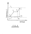
- this represents the well-known thermal cycle of a steam power station with turbine generator.
- the temperature of the heat source of the system is represented by a broken line 1 and the temperature of a heat sink, for example a source of cold water, is represented by broken line 2.
- the temperature rise represented by the line between points 3 and 4 corresponds to an increase in pressure between a condenser output and the input to the water heating system.
- the line between points 4 and 5 corresponding to heating of the water.
- the line between points 5 and 6 corresponds to the formation of steam at a stable temperature corresponding to the boiling point of water.
- the line between points 6 and 7 corresponding to super-heating of the previously formed steam.
- the line between points 7 and 8a corresponds to the extraction of energy from the super-heated steam by the driven turbine. (The line between points 6 and 8b corresponds to the alternative of extraction of energy from saturated steam).
- the line between points 8a and 3 corresponds to the residual heat rejected to the heat sink.
- the spacing between the line from points 8a or 8b to 3 and broken line 2 corresponds to the difference between the temperature of the gas in the condenser and the temperature of the coolant. The smaller this difference can be made, the greater will be the efficiency of the generating system as the steam delivered to the turbine will expand to a lower pressure, thereby generating more electricity and increasing the efficiency of the cycle.
- the present invention enables this temperature difference to be reduced.
- FIGs 6 and 7 the structure of a known steam condenser is illustrated in general terms.
- such condensers comprise a nest of horizontally extending tubes which carry cooling water, steam to be condensed being arranged to flow inwards from the exterior of the nest to an open region at the centre.
- broken lines 9 represents the outer periphery of the nest of tubes, and broken lines 10 the inner limit of the nest of tubes.
- the central open region is represented by the area 11.
- Steam flowing radially inwards is represented by arrows 12.
- Flow 13 in Figs 6 and 7 represent the off-take for air and the residue of steam that has not condensed.
- a condensate collection system 14 collects falling water droplets, the flow of condensate being extracted via outlet 15.
- One of the nested tubes is represented by component 16 in Figure 7 .
- Fig 7 indicates that the pipe work for the extract flow 13 for the known steam condenser has to pass through the bulk gas.
- the gas flowing through this pipe work contains a significant proportion of gas that could potentially be condensed.
- the pipe work, pump and fittings have to be sized appropriately. This is expensive.
- the pump consumes energy.
- thermally isolating or insulating this extract system from the effects of the bulk gas to prevent condensate from being re-evaporated and the extracted gas being re-heated. Both effects will increase the volume flow rate of gas, which increases the backpressure, thus offsetting some potential benefits of the design.
- Droplets of water falling off the condenser tubes are at approximately the same temperature as the surface of the tubes. Therefore, adjacent to where these droplets are formed, the air mass fraction is high. As the droplets fall through the local steam/air mixture they are heated up to the temperature of that mixture, and the air mass fraction reduces. Accordingly, if gas is removed from the structure at locations where the gas mixture is still relatively cool, the proportion of air in the removed gas is relatively high.
- Tube 17 represents the position of a tube adjacent the open interior of the structure
- tube 18 represents the lowermost tube in the structure.
- Cold coolant is introduced to the left hand end of these tubes (in the example above at a temperature of 10°C) as indicated by arrows 19, and the heated coolant (in the example above water at a temperature of 20°C) issues from these tubes as represented by arrows 20.
- air extract ducts 21 are provided, the inlet ends of these ducts being located beneath droplet deflectors 22 arranged to prevent any droplets of water entering the air extract ducts 21.
- the uppermost duct 21 is placed adjacent the interior of the tube nest. (The flow of steam is perpendicular to the axis of the tube as represented by arrow 23).
- the lowermost duct 21 is located at the bottom of the structure given that there is a tendency for gas incorporating a large volume of air to fall to the bottom of the structure.
- Fig 8 represents a single vertical section through the tube structure and accordingly it will be appreciated that ducts 21 will be distributed in a direction perpendicular to the plane of Fig 8 .
- any convenient structure could be provided to prevent condensate being extracted through the air extract duct 21.
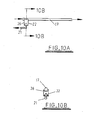
- the simple "roof' structure shown in Figure 8 could be substituted for example by a pipe with orifices in the bottom as shown in Figures 9A and 9B, Figure 9B being a section on line 9B to 9B of Figure 9A , or by a member of inverted U-shaped section as shown in Figures 9C and 9D, Figure 9D being a section on line 9D-9D of Figure 9C or by a rectangular channel with a slot cut in its base or the like.
- an array of interconnected extract pipes 21 could extend perpendicular to the tubes 18.
- a shield could be provided to protect the falling droplets of cold condensate and surrounding cold gas from the temperature and velocity of the hotter flow of the bulk gas, which would reduce the mass fraction of non-condensing gas.
- Figures 10A and 10B represent such a shield, the side elevation of Figure 10A showing the axial length of the shield 26 is as short as is necessary to protect the gas extract.
- the shield 26 is generally cylindrical, with its lower edge surrounding the deflector 22 and its upper edge extending to adjacent the tube 17.
- the end elevation of Figure 10B shows the clearance around the coolant tube and deflector is small.
- air is extracted from the coldest points within the structure.
- the appropriate positions of air extract ducts can be determined by measurement of the temperatures of the structure before modification. It will of course be appreciated that falling droplets of condensate create a localised volume of high air mass fraction which makes an arrangement such as that illustrated in Fig 8 particularly appropriate.
- the air extract ducts reduce the concentration and partial pressure of air in the localised volumes of highest concentration, and then diffusion processes reduce the concentration of air throughout the structure. Hence, even if air is extracted from only a limited number of regions of the structure, the heat transfer processes of the condenser will be improved throughout the structure.
- An auxiliary cooling system or sub-condenser, could be installed to create localised volumes of very high air mass fraction, and additional air extract points located appropriately. For example, in generating plant where cooling towers form the main heat sink, make-up water could be colder than water from the cooling towers and would provide an appropriate heat sink. Alternatively a dedicated supply could be installed. An effective approach would be to install a plant to freeze out the remaining potential condensate. One approach would be to utilise covers used during construction or for inspection. Figure 11 illustrates a modified cover provided for this purpose.
- the condensate pressure vessel has a wall 27 defining an aperture covered by a plate 28 insulated from the wall 27 by a thermally insulating gasket 29.
- the plate 28 defines many small diameter passages (only two of which are shown) communicating with a manifold connected by a suitable pipe 30 to a pump 31 and a flow meter 32. Cooling and heating coils (not shown) are incorporated in a body 33 in good thermal contact with the plate 28.
- a pressure sensor and a temperature sensor sense the pressure adjacent the plate 28 and the temperature of the plate 28.
- the cooling and heating coils would be controlled to maintain the temperature of the centre of the plate 28 at just above the freezing point of water given the sensed pressure, thereby maximising the air fraction in the condenser adjacent the plate 28 and therefore maximising the air fraction in the extracted flow. If the flow-meter was to detect zero flow and the sensed temperature indicates there could be frozen water in the extract system, the control system would reduce the cooling air or if necessary halt cooling and turn on the heating coils.
- a localised "cool spot” is produced by cooling a modified cover plate adjacent which a relatively high concentration of air accumulates.
- Alternative approaches may be adopted to produce a localised cool spot. For example, in a condenser in which a condensate pool forms all or part of the condensate pool could itself be cooled so as to encourage concentration of air adjacent the pool. Gas would then be extracted from adjacent the condensate pool.
- straight-through flow is used to indicate a condenser in which steam with entrained air enters the condenser through an upper end of condenser housing, air being extracted from suitable locations which correspond to localised cool spots resulting from for example falling droplets of condensate or at the bottom of the structure just above a condensate pool. In the latter case, the area of the condensate pool should be as large as possible.
- the condensate pool could incorporate its own heat exchanger, perhaps cooled by a flow of coolant at the coolant inlet temperature of the condenser. This would offset any potential for incoming steam to evaporate condensate. The residual of the vertical downwards flow of steam would impinge on the condensate in the condensate pool and some of the residual steam would condense.
- a further advantage of such a condenser geometry is that the bulk flow of gas is always in the same (vertical) direction, emitting energy losses due to changes in the direction of flow within the condenser. The pressure at the outlet from the turbine could thereby be further reduced.
- FIG. 12 An incoming air and steam flow is represented by arrow 34.
- the incoming flow passes through a condenser having an outer body 35 and condensate is collected in a condensate pool 36.
- the condensate pool 36 has a large free surface area.
- a heat exchanger 37 is in contact with the condensate pool 36 so as to cool condensate within the pool. The result is a concentration of air immediately above the free surface of the condensate in the pool.
- a nest of horizontal tubes represented by area 38 is located above the condensate pool, condensing out water dripping from those tubes into the condensate pool 36.
- An auxiliary cooling device 39 may also be provided to produce a further cool spot in a manner analogous to that described with reference to Figure 11 .
- the auxiliary cooling device 39 could be for example mounted on a removable plate.
- An outlet (not shown) for non-condensing gas could be provided in association with the auxiliary cooling device 39.
- a non-condensing gas outlet 40 is provided, the outlet extending from beneath a droplet deflector 41 similar to the deflector 22 of Figure 10 .
- the outlet 40 is located just above the surface of the condensate pool 36 so as to remove the gas of high air content which accumulated immediately above the condensate.
- Condensate will be removed from the condensate pool 36 as indicated by flow 42. That flow may be passed through an auxiliary heat exchanger 42a located at the top of the condenser so as to reheat the condensate by absorbing energy from the incoming flow of steam and air if condensate reheat is required in a particular application.
- a conventional condenser design in which the bulk gas flows inwards has the advantage that the cross-sectional area of the flow reduces from the inlet to the outlet, thereby partially offsetting the reducing gas velocity which results from the reducing mass flow as gas is condensed out of the mixture. This reduction in cross-sectional flow area to an extent mitigates the adverse effects on the condensation process of the increasing mass fraction of the non-condensing gas.
- a straight-through design such as that illustrated in Figure 12 does not provide the advantages of an inwards flow but nevertheless careful location of the various extraction devices through which non-condensing gases are removed from the condenser still delivers a considerable overall benefit.
- the design of a turbine/condenser combination will be selected with a view to optimising performance given the conditions that apply in the particular application, for example in dependence upon the source of cooling water from the sea, a river or a lake, the use of wet or dry cooling towers as the final heat sink etc.
- the designer will have to make a choice between the minimum cost of condenser (by minimising the size and the area of the heat transfer surface) or accepting a larger condenser to enable the use of cheaper components or design of heat sink to reduce the overall capital cost.
- the final choice will depend therefore on the site and the economic requirements, for example whether or not the lowest possible capital cost or the lowest possible long term running cost is required.
- Figure 13 shows a refinement of the design outlined in Figure 12 in which the main tube nest which is shown as a unitary assembly 38 in Figure 12 is split into a pair of in-line sections 43, 44. It will be appreciated of course that more than two in-line sections could be used in an assembly of the general type illustrated in Figure 13 . Where appropriate the same reference numerals are used in Figure 13 as in Figure 12 .
- the tube nest sections 43 and 44 of Figure 13 could define separate primary and secondary heat exchangers with separate heat sinks, the secondary heat exchanger 44 being supplied with coolant at a temperature which is lower than the temperature of coolant supply to the primary heat exchanger 43. Condensate dripping off the relatively cold secondary heat exchanger 44 will be colder than condensate falling off the primary heat exchanger 43, enhancing the concentration of cold gas of high air content in the region from which gas is withdrawn from the condenser body 35. The lower secondary heat exchanger 44 will reject residual heat and could be designed so that only a small proportion of the total steam condensed would be condensed within the tube nest 44.
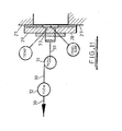
- Figure 14 schematically illustrates a simple arrangement in which the flow of cooling water can make more than one pass through the condenser. Such an arrangement can reduce the temperature difference between the gas mixture at entry and the first tubes encountered by the mixture towards the top of the condenser whilst maintaining an adequate temperature differential between the gas mixture flow and the tubes which are lower down in the tube nest.
- the incoming steam and air mixture is represented by arrow 45
- the condenser housing is represented by the rectangle 46
- the condensate pool is represented by the shaded area 47.
- Air is extracted as represented by arrow 48 from immediately above the condensate pool and condensate is removed as indicated by arrow 49.
- the tube nest incorporates an upper tube 50 and a lower tube 51 which are connected in series such that coolant enters tube 51 at point A, flows from tube 51 to tube 50 via points B and C, and exits the condenser at point D.
- the coolant within tube 51 will be colder than the coolant within tube 50.
- Figure 15 illustrates an alternative flow pattern in which a coolant enters a condenser 52 at point A to pass through a tube 53 and exit the condenser at point B. That flow is then transferred to point C, flows through tube 54 and exits the condenser at point D. A second flow enters the condenser at point E and traverses the condenser in tube 55, exits the condenser at point F, re-enters the condenser at point G and traverses the condenser through tube 56, leaving the condenser at point H.
- first and second series connected tube pairs 53, 54 and 55, 56 are spaced apart in both the vertical and horizontal directions.
- the first flow enters from one side of the condenser (the side of points A, D, F and G) whereas the other flow enters from the other side of the condenser (the side of points B, C, E and H).
- coolant flows in one direction in the first tube 53 of the first pair and the second tube 56 of the second pair, but in the opposite direction in the second tube 54 of the first pair and the first tube 55 of the second pair.
- each tube 53 and 56 are spaced apart in the process flow direction, as are the tubes 54 and 55.
- each tube can be designed to remove a similar quantity of heat as vertically spaced points on tube pairs 53, 56 and 54, 55 are always at different temperatures.
- the temperature of the coolant at point A will be 10°, at points B and C 15°C, and at point D 20°C.
- the temperature at point E may be 10°C
- the temperature at points F and G may be 15°C
- the point H at the final exit temperature of 20°C.
- condenser tube nests are generally described as being made up from a series of parallel horizontal tubes.
- the cooling tubes could be vertical and adopting such a design would provide an alternative method for maintaining a good temperature difference between the gas mixture and the tubes throughout the tube nest.
- bulk gas could be passed through the condenser in a vertically condensing gas flow and coolant could be passed through the condenser in vertical tubes with the coolant flowing vertically upwards through the tubes. This would improve condensation heat transfer as compared with conventional designs, and therefore the surface area of the tubes making up the nest could be smaller than in current designs.
- the coolant temperature varies in direction which is transverse to the vertical component of the flow of bulk gas and thus alters the heat transfer characteristics across the width of the structure.
- the heat transfer characteristics are constant across any horizontal plane.
- the temperature of the coolant at the coolant outlet can therefore be higher and nearer to that of the bulk gas inlet. This effect is integrated throughout the condenser, and so the overall flow of coolant can be reduced, thereby saving pumping power. Some adverse effects may arise however if it is necessary to dilute the outlet flow with further coolant to reduce the discharge temperature to the local environment.
- the upper ends of the vertical tubes could be connected to an outlet header above the tube nest which does not have to be thermally insulated from the bulk gas as its additional cooling effect could be beneficial.
- An inlet header at the bottom of the tube nest could be immersed in a condensate pool in order to cool the pool, thereby ensuring the accumulation of non-condensing gases adjacent the cooling pool.
- the inlet header could be thermally isolated if it was thought necessary to eliminate condensate sub-cooling in order to maintain desired control over the entire plant.
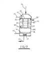
- FIG. 17 illustrates such an arrangement.
- An incoming air and steam flow is represented by arrow 34.
- the incoming flow 34 is incident upon an upper tube plate 65.
- Tube plate 65 is supported by (and sealed to) an annular support 66 extending around the interior of the outer body 35.
- the incoming flow passes through an array of vertical tubes 67 forming a single tube nest.
- the upper ends of the tubes are sealed to the upper tube plate 65, such that the tubes 67 connect with the upper part of the condenser.
- the lower ends of the tubes 67 are sealed to a lower tube plate 68, such that the tubes 67 connect with the lower part of the condenser allowing process fluid to flow through the tubes.
- An array of baffles 71 are incorporated into the volume between the upper and lower tube plates. These extend partway transverse the condenser, e.g. across the width of the condenser.
- the array of baffles is staggered, with alternate baffles extending from opposite sides of the condenser.
- the baffles 71 define an array of parallel heat exchanger conduits. Coolant is passed into the conduits at a lower inlet 69 and exits via an upper outlet 70.
- the conduits extend in series, such that coolant will flow in one direction along a first of the conduits, and in the opposite direction along the next, adjacent conduit.
- Condensate condenses on the inside of tubes 67. Condensate then collects in a condensate pool 36.
- the condensate pool 36 is in contact with a heat exchanger 37 to cool the condensate, as described above in relation to Figure 12 .
- a condensate outlet 42 is provided.
- Non condensing gas outlets 40 are incorporated both in the volume above upper tube plate 65 and in the volume below lower tube plate 68. Incorporating a non condensing gas outlet 40 in the volume above upper tube plate 65 allows the counteraction of any leakage of air into this portion of the condenser through outer body 35. Additionally, this non condensing gas outlet 40 can also serve to maximise the condensation in the tubes. Non condensing gas outlet 40 in the volume below the lower tube plate 68 allows air to be removed on start up of the condensation process, and the counteraction any leakage of air into this portion of the condenser through outer body 35.
- non condensing gas outlets 40 are shown in conjunction with droplet deflectors 41 as described above in relation to Figure 12 . It will be appreciated that this outlet design may be replaced by the non condensing gas outlet of Figure 11 .
- a disadvantage of a vertical tube design is that the thickness of the condensate on the cooling tubes will increase with distance down the tubes. This therefore presents a greater resistance to the heat flux than for horizontal tube designs.
- the tubes could be arranged so as to encourage the formation of droplets so that the droplets fall off the tube.
- the tubes could be arranged at a small angle from the vertical.
- the tube surfaces may be shaped to promote break-up of the condensate into droplets by surface roughening or the addition of short fins.
- a helical fin design could be considered.
- FIG 16 this schematically illustrates a containment vessel of a water-cooled nuclear reactor.
- the containment vessel has an outer wall 57 which is intended to prevent the release of gas to the local environment in the event of an excess pressure building up within the containment vessel.
- Housed within the containment vessel are a steam generator 58, a nuclear reactor 59 and a reactor coolant pump 60.
- the steam generator delivers steam to a turbine (not shown) through pipe 61 and receives condensate from the turbine through pipe 62.
- Spray heads 63 are located in an upper section of the containment vessel.
- Large surface area trays 64 are provided on the floor of the containment vessel such that condensate formed within the containment vessel will accumulate in those pools.
- trays 64 are indicated as providing a way to produce large surface area pools of condensate.
- These trays could for example be defined by relatively small (in the vertical direction) formations on a floor across which personnel normally simply walk.
- the effect of having a pool of condensate on the peak pressure within the containment vessel could be further enhanced by ensuing a very rapid formation of a pool of coolant rather than waiting for a pool of coolant to accumulate as a result of steam condensation.
- a tank of water could be provided which would be rapidly discharged into a tray such as that shown in Figure 16 as soon as the pressure within the containment vessel exceeded a predetermined threshold.
- the present invention relates to condensers which typically are provided for the express purpose of converting a gas to a condensate.
- apparatus is manufactured which is not typically referred to as a "condenser” but which relies upon condensation processes and it is the intention that the present invention should encompass such apparatus.
- sterilisers are widely used which rely upon the injection of steam into an enclosure to sterilise both the enclosure and articles placed within that enclosure.
- the enclosure is initially filled with air and a predetermined time is specified for purging the air by injecting sufficient steam so that the initial atmosphere of air within the enclosure at ambient pressure is converted to pressurised saturated steam.
- the interior of the enclosure is pumped out or simply vented to atmosphere to remove air.
- the air off-take pipe is located at the top of the enclosure. As a result the process of evacuating air from the enclosure is relatively slow. If the air off-take was located so as to extract gas from a region within the enclosure which is at a relatively low temperature, for example a region adjacent the bottom of the steriliser or adjacent a cooling device provided to produce a localised region of low temperature, the rate at which air could be removed from the steriliser would be significantly increased. This in turn would reduce the period required for the purging process.
- the invention applies the same principle to the extraction of unwanted non-condensing gases as is applied in the case of condensers for steam in electric power generation plant.
- the same principles can of course be applied in apparatus other than sterilisers, for example heat exchangers in oil refineries or other chemical engineering plant where there is a need to remove non-condensing gases from a mixture of condensing and non-condensing gases.
Landscapes
- Chemical & Material Sciences (AREA)
- Chemical Kinetics & Catalysis (AREA)
- Engineering & Computer Science (AREA)
- Analytical Chemistry (AREA)
- General Chemical & Material Sciences (AREA)
- Oil, Petroleum & Natural Gas (AREA)
- Physics & Mathematics (AREA)
- Thermal Sciences (AREA)
- Heat-Exchange Devices With Radiators And Conduit Assemblies (AREA)
- Structure Of Emergency Protection For Nuclear Reactors (AREA)
- Vaporization, Distillation, Condensation, Sublimation, And Cold Traps (AREA)
Applications Claiming Priority (2)
| Application Number | Priority Date | Filing Date | Title |
|---|---|---|---|
| GBGB0308657.6A GB0308657D0 (en) | 2003-04-15 | 2003-04-15 | Condensation processes |
| EP04726202A EP1613412B1 (fr) | 2003-04-15 | 2004-04-07 | Procede de condensation |
Related Parent Applications (2)
| Application Number | Title | Priority Date | Filing Date |
|---|---|---|---|
| EP04726202.7 Division | 2004-04-07 | ||
| EP04726202A Division-Into EP1613412B1 (fr) | 2003-04-15 | 2004-04-07 | Procede de condensation |
Publications (2)
| Publication Number | Publication Date |
|---|---|
| EP2422860A2 true EP2422860A2 (fr) | 2012-02-29 |
| EP2422860A3 EP2422860A3 (fr) | 2012-08-29 |
Family
ID=9956798
Family Applications (2)
| Application Number | Title | Priority Date | Filing Date |
|---|---|---|---|
| EP11008452A Withdrawn EP2422860A3 (fr) | 2003-04-15 | 2004-04-07 | Procédé de condensation et condensateur |
| EP04726202A Expired - Lifetime EP1613412B1 (fr) | 2003-04-15 | 2004-04-07 | Procede de condensation |
Family Applications After (1)
| Application Number | Title | Priority Date | Filing Date |
|---|---|---|---|
| EP04726202A Expired - Lifetime EP1613412B1 (fr) | 2003-04-15 | 2004-04-07 | Procede de condensation |
Country Status (4)
| Country | Link |
|---|---|
| US (2) | US7780767B2 (fr) |
| EP (2) | EP2422860A3 (fr) |
| GB (1) | GB0308657D0 (fr) |
| WO (1) | WO2004091752A1 (fr) |
Families Citing this family (10)
| Publication number | Priority date | Publication date | Assignee | Title |
|---|---|---|---|---|
| US8206656B2 (en) * | 2008-07-30 | 2012-06-26 | Ford Global Technologies, Llc | Freezable-liquid dispenser for motor vehicles |
| US20120255712A1 (en) * | 2011-04-07 | 2012-10-11 | Basf Se | Apparatus and method for condensing vapor in a vessel |
| US11300370B2 (en) * | 2014-12-29 | 2022-04-12 | The United States Of America As Represented By The Secretary Of The Army | Methods and apparatus for dropwise excitation heat transfer |
| CN106500433B (zh) * | 2016-12-14 | 2022-03-01 | 天津市天商冰源科技发展有限公司 | 一种冷库气压平衡器 |
| CN108379997B (zh) * | 2018-04-13 | 2023-04-18 | 郑州轻工业学院 | 小型多通道蒸汽冷凝集液器 |
| US20210008464A1 (en) * | 2019-07-08 | 2021-01-14 | United States Of America As Represented By The Administrator Of Nasa | Spacecraft atmosphere co2 capture via deposition |
| CN111861005B (zh) * | 2020-07-22 | 2021-10-19 | 西安交通大学 | 一种预测倾斜平板上冷凝液体滴落量的方法 |
| CN117753154B (zh) * | 2024-01-02 | 2024-08-20 | 百仑生物科技(江苏)有限公司 | 一种发酵罐的尾气冷凝、调节一体化处理装置 |
| CN118856352B (zh) * | 2024-07-25 | 2025-10-24 | 浙江工业大学台州研究院 | 一种高效节能的耐腐蚀智能温控震动烟气冷凝系统 |
| CN119903785B (zh) * | 2025-02-11 | 2026-01-27 | 北京广厦环能科技股份有限公司 | 一种真空冷凝器的设计方法 |
Family Cites Families (10)
| Publication number | Priority date | Publication date | Assignee | Title |
|---|---|---|---|---|
| US1585640A (en) * | 1926-01-08 | 1926-05-25 | Ingersoll Rand Co | Surface condenser |
| US1941650A (en) * | 1929-10-16 | 1934-01-02 | Westinghouse Electric & Mfg Co | Surface condenser |
| NL72565C (fr) * | 1949-04-21 | |||
| US3410724A (en) * | 1963-12-30 | 1968-11-12 | Hercules Inc | Cleaning or treating process |
| US3884768A (en) * | 1972-03-02 | 1975-05-20 | Joseph W Griffith | Reclamation of non-combustible liquids by direct flame vaporization, centrifugal solids separation and subsequent condensation |
| FI82386C (fi) * | 1989-05-31 | 1991-03-11 | Inventio Oy | Tvaostegskondensor. |
| DE4202802A1 (de) | 1992-01-31 | 1993-08-05 | Seiler Wolfram | Vorrichtung zum kuehltrocknen von gasen |
| DE4239021A1 (de) * | 1992-11-19 | 1994-05-26 | Linde Kca Dresden Gmbh | Verfahren zur Abtrennung gasförmiger Komponenten aus wasserstoffhaltigen Synthesepurgegasen |
| US5534230A (en) * | 1994-07-05 | 1996-07-09 | The Babcock & Wilcox Company | Segmented heat exchanger flue gas treatment |
| DE19703681A1 (de) | 1997-01-31 | 1998-08-06 | Linde Ag | Verfahren und Vorrichtung zur Entfernung von kondensierbaren Komponenten aus Gasen und/oder Gasgemischen |
-
2003
- 2003-04-15 GB GBGB0308657.6A patent/GB0308657D0/en not_active Ceased
-
2004
- 2004-04-07 EP EP11008452A patent/EP2422860A3/fr not_active Withdrawn
- 2004-04-07 US US10/553,541 patent/US7780767B2/en not_active Expired - Fee Related
- 2004-04-07 WO PCT/GB2004/001511 patent/WO2004091752A1/fr not_active Ceased
- 2004-04-07 EP EP04726202A patent/EP1613412B1/fr not_active Expired - Lifetime
-
2010
- 2010-08-16 US US12/856,744 patent/US8092580B2/en not_active Expired - Fee Related
Non-Patent Citations (3)
| Title |
|---|
| J A ROBINSON ET AL.: "Measurements of Condensation Heat Transfer Using a Variable Conductance Heat Pipe", SECOND UK NATIONAL HEAT TRANSFER CONFERENCE, 1988 |
| J G COILIER: "Convective Boiling and Condensation" |
| J W ROSE: "Condensation of a Vapour in the Presence of a Non-conducting Gas", INT J HEAT MASS TRANSFER, vol. 12, 1969, pages 233 - 237 |
Also Published As
| Publication number | Publication date |
|---|---|
| US7780767B2 (en) | 2010-08-24 |
| EP1613412B1 (fr) | 2012-10-24 |
| US8092580B2 (en) | 2012-01-10 |
| WO2004091752A1 (fr) | 2004-10-28 |
| EP1613412A1 (fr) | 2006-01-11 |
| US20100307192A1 (en) | 2010-12-09 |
| EP2422860A3 (fr) | 2012-08-29 |
| GB0308657D0 (en) | 2003-05-21 |
| US20070089445A1 (en) | 2007-04-26 |
Similar Documents
| Publication | Publication Date | Title |
|---|---|---|
| US8092580B2 (en) | Condensation process and containment vessel | |
| CN107210071A (zh) | 安全壳内部的非能动除热系统 | |
| US6241009B1 (en) | Integrated heat pipe vent condenser | |
| US4072183A (en) | Heat exchanger with intermediate evaporating and condensing fluid | |
| Oh et al. | Complete condensation in a vertical tube passive condenser | |
| Darwish et al. | Developments in the multi-stage flash desalting system | |
| AU2002252680B2 (en) | Condensers and their monitoring | |
| RU2565650C1 (ru) | Деаэратор (варианты) | |
| RU2371632C1 (ru) | Вертикальный подогреватель | |
| RU2614266C1 (ru) | Кожухотрубный теплообменник | |
| Carlucci | Computations of flow and heat transfer in power plant condensers | |
| RU2305226C1 (ru) | Поверхностный подогреватель | |
| RU2278323C1 (ru) | Теплообменник | |
| WO2017176239A1 (fr) | Échangeur de chaleur | |
| Morozov et al. | An experimental study of a VVER reactor’s steam generator model operating in the condensing mode | |
| Oh et al. | Investigation of the noncondensable effect and the operational modes of the passive condenser system | |
| RU2366859C1 (ru) | Вертикальный подогреватель | |
| KR20210131490A (ko) | 전열촉진관부의 평균열전달계수 감소값 측정을 위한 시험장치 및 시험방법 | |
| RU2378571C1 (ru) | Вертикальный теплообменник | |
| Suen et al. | Analysis and optimization of circulating cooling technology of super heavy oil steam spray | |
| RU2775748C1 (ru) | Пароперегреватель турбоустановки | |
| SU1672187A1 (ru) | Установка дл охлаждени | |
| RU2303475C1 (ru) | Многоступенчатый испаритель мгновенного вскипания | |
| CN111664439A (zh) | 一种定期排污扩容器 | |
| US20160216040A1 (en) | Heat exchanger |
Legal Events
| Date | Code | Title | Description |
|---|---|---|---|
| AC | Divisional application: reference to earlier application |
Ref document number: 1613412 Country of ref document: EP Kind code of ref document: P |
|
| AK | Designated contracting states |
Kind code of ref document: A2 Designated state(s): AT BE BG CH CY CZ DE DK EE ES FI FR GB GR HU IE IT LI LU MC NL PL PT RO SE SI SK TR |
|
| PUAI | Public reference made under article 153(3) epc to a published international application that has entered the european phase |
Free format text: ORIGINAL CODE: 0009012 |
|
| PUAL | Search report despatched |
Free format text: ORIGINAL CODE: 0009013 |
|
| AK | Designated contracting states |
Kind code of ref document: A3 Designated state(s): AT BE BG CH CY CZ DE DK EE ES FI FR GB GR HU IE IT LI LU MC NL PL PT RO SE SI SK TR |
|
| RIC1 | Information provided on ipc code assigned before grant |
Ipc: B01D 53/00 20060101AFI20120720BHEP Ipc: B01D 53/26 20060101ALI20120720BHEP Ipc: B01D 5/00 20060101ALI20120720BHEP |
|
| STAA | Information on the status of an ep patent application or granted ep patent |
Free format text: STATUS: THE APPLICATION IS DEEMED TO BE WITHDRAWN |
|
| 18D | Application deemed to be withdrawn |
Effective date: 20130301 |