EP2422870A1 - Extraktion von CO2-Gas - Google Patents
Extraktion von CO2-Gas Download PDFInfo
- Publication number
- EP2422870A1 EP2422870A1 EP10177231A EP10177231A EP2422870A1 EP 2422870 A1 EP2422870 A1 EP 2422870A1 EP 10177231 A EP10177231 A EP 10177231A EP 10177231 A EP10177231 A EP 10177231A EP 2422870 A1 EP2422870 A1 EP 2422870A1
- Authority
- EP
- European Patent Office
- Prior art keywords
- vessel
- liquid medium
- gas
- organisms
- medium
- Prior art date
- Legal status (The legal status is an assumption and is not a legal conclusion. Google has not performed a legal analysis and makes no representation as to the accuracy of the status listed.)
- Withdrawn
Links
- 238000000605 extraction Methods 0.000 title claims abstract description 40
- 239000007788 liquid Substances 0.000 claims abstract description 185
- 239000007789 gas Substances 0.000 claims abstract description 155
- CURLTUGMZLYLDI-UHFFFAOYSA-N Carbon dioxide Chemical compound O=C=O CURLTUGMZLYLDI-UHFFFAOYSA-N 0.000 claims abstract description 84
- 229910002092 carbon dioxide Inorganic materials 0.000 claims abstract description 42
- XLYOFNOQVPJJNP-UHFFFAOYSA-N water Substances O XLYOFNOQVPJJNP-UHFFFAOYSA-N 0.000 claims abstract description 36
- VNWKTOKETHGBQD-UHFFFAOYSA-N methane Chemical compound C VNWKTOKETHGBQD-UHFFFAOYSA-N 0.000 claims abstract description 34
- 239000001569 carbon dioxide Substances 0.000 claims abstract description 22
- 239000003345 natural gas Substances 0.000 claims abstract description 17
- 238000003306 harvesting Methods 0.000 claims abstract description 14
- 230000000243 photosynthetic effect Effects 0.000 claims abstract description 12
- 230000006835 compression Effects 0.000 claims abstract description 5
- 238000007906 compression Methods 0.000 claims abstract description 5
- 238000000034 method Methods 0.000 claims description 32
- 238000010276 construction Methods 0.000 claims description 20
- 238000010438 heat treatment Methods 0.000 claims description 20
- 238000012546 transfer Methods 0.000 claims description 15
- 238000002485 combustion reaction Methods 0.000 claims description 14
- 239000002803 fossil fuel Substances 0.000 claims description 13
- 238000004140 cleaning Methods 0.000 claims description 11
- 238000004891 communication Methods 0.000 claims description 8
- 230000014759 maintenance of location Effects 0.000 claims description 3
- 241000195493 Cryptophyta Species 0.000 description 44
- 230000012010 growth Effects 0.000 description 16
- 235000015097 nutrients Nutrition 0.000 description 15
- 230000008569 process Effects 0.000 description 13
- 239000000463 material Substances 0.000 description 11
- 238000012545 processing Methods 0.000 description 11
- 239000000446 fuel Substances 0.000 description 9
- 239000000203 mixture Substances 0.000 description 8
- 238000001816 cooling Methods 0.000 description 7
- 230000005611 electricity Effects 0.000 description 7
- 238000005286 illumination Methods 0.000 description 7
- 239000000919 ceramic Substances 0.000 description 6
- 238000000926 separation method Methods 0.000 description 6
- QVGXLLKOCUKJST-UHFFFAOYSA-N atomic oxygen Chemical compound [O] QVGXLLKOCUKJST-UHFFFAOYSA-N 0.000 description 5
- 239000001301 oxygen Substances 0.000 description 5
- 229910052760 oxygen Inorganic materials 0.000 description 5
- 239000003225 biodiesel Substances 0.000 description 4
- 239000012530 fluid Substances 0.000 description 4
- 230000029553 photosynthesis Effects 0.000 description 4
- 238000010672 photosynthesis Methods 0.000 description 4
- 238000013021 overheating Methods 0.000 description 3
- 230000037361 pathway Effects 0.000 description 3
- 239000000047 product Substances 0.000 description 3
- IJGRMHOSHXDMSA-UHFFFAOYSA-N Atomic nitrogen Chemical compound N#N IJGRMHOSHXDMSA-UHFFFAOYSA-N 0.000 description 2
- 241000894006 Bacteria Species 0.000 description 2
- LYCAIKOWRPUZTN-UHFFFAOYSA-N Ethylene glycol Chemical compound OCCO LYCAIKOWRPUZTN-UHFFFAOYSA-N 0.000 description 2
- 238000013019 agitation Methods 0.000 description 2
- 230000005791 algae growth Effects 0.000 description 2
- 230000003247 decreasing effect Effects 0.000 description 2
- 230000000694 effects Effects 0.000 description 2
- 230000003450 growing effect Effects 0.000 description 2
- 238000002347 injection Methods 0.000 description 2
- 239000007924 injection Substances 0.000 description 2
- 238000004519 manufacturing process Methods 0.000 description 2
- 238000012544 monitoring process Methods 0.000 description 2
- 231100000331 toxic Toxicity 0.000 description 2
- 230000002588 toxic effect Effects 0.000 description 2
- 241001269539 Spirolina Species 0.000 description 1
- 230000009471 action Effects 0.000 description 1
- 239000000654 additive Substances 0.000 description 1
- 150000001412 amines Chemical class 0.000 description 1
- 230000008901 benefit Effects 0.000 description 1
- 239000006227 byproduct Substances 0.000 description 1
- 238000006243 chemical reaction Methods 0.000 description 1
- 229930002875 chlorophyll Natural products 0.000 description 1
- 235000019804 chlorophyll Nutrition 0.000 description 1
- ATNHDLDRLWWWCB-AENOIHSZSA-M chlorophyll a Chemical compound C1([C@@H](C(=O)OC)C(=O)C2=C3C)=C2N2C3=CC(C(CC)=C3C)=[N+]4C3=CC3=C(C=C)C(C)=C5N3[Mg-2]42[N+]2=C1[C@@H](CCC(=O)OC\C=C(/C)CCC[C@H](C)CCC[C@H](C)CCCC(C)C)[C@H](C)C2=C5 ATNHDLDRLWWWCB-AENOIHSZSA-M 0.000 description 1
- 239000000356 contaminant Substances 0.000 description 1
- 239000012809 cooling fluid Substances 0.000 description 1
- 230000001351 cycling effect Effects 0.000 description 1
- 230000007423 decrease Effects 0.000 description 1
- 230000005484 gravity Effects 0.000 description 1
- WGCNASOHLSPBMP-UHFFFAOYSA-N hydroxyacetaldehyde Natural products OCC=O WGCNASOHLSPBMP-UHFFFAOYSA-N 0.000 description 1
- 239000011810 insulating material Substances 0.000 description 1
- 230000010354 integration Effects 0.000 description 1
- 150000002500 ions Chemical class 0.000 description 1
- 238000002156 mixing Methods 0.000 description 1
- 238000012986 modification Methods 0.000 description 1
- 230000004048 modification Effects 0.000 description 1
- 229910052757 nitrogen Inorganic materials 0.000 description 1
- 239000013307 optical fiber Substances 0.000 description 1
- 230000035515 penetration Effects 0.000 description 1
- 239000003208 petroleum Substances 0.000 description 1
- 230000009467 reduction Effects 0.000 description 1
- 238000011160 research Methods 0.000 description 1
- 238000007790 scraping Methods 0.000 description 1
- 230000009919 sequestration Effects 0.000 description 1
- 238000010008 shearing Methods 0.000 description 1
- 239000000243 solution Substances 0.000 description 1
- 230000000638 stimulation Effects 0.000 description 1
- 239000002699 waste material Substances 0.000 description 1
Images






Classifications
-
- C—CHEMISTRY; METALLURGY
- C12—BIOCHEMISTRY; BEER; SPIRITS; WINE; VINEGAR; MICROBIOLOGY; ENZYMOLOGY; MUTATION OR GENETIC ENGINEERING
- C12M—APPARATUS FOR ENZYMOLOGY OR MICROBIOLOGY; APPARATUS FOR CULTURING MICROORGANISMS FOR PRODUCING BIOMASS, FOR GROWING CELLS OR FOR OBTAINING FERMENTATION OR METABOLIC PRODUCTS, i.e. BIOREACTORS OR FERMENTERS
- C12M21/00—Bioreactors or fermenters specially adapted for specific uses
- C12M21/02—Photobioreactors
-
- B—PERFORMING OPERATIONS; TRANSPORTING
- B01—PHYSICAL OR CHEMICAL PROCESSES OR APPARATUS IN GENERAL
- B01D—SEPARATION
- B01D53/00—Separation of gases or vapours; Recovering vapours of volatile solvents from gases; Chemical or biological purification of waste gases, e.g. engine exhaust gases, smoke, fumes, flue gases, aerosols
- B01D53/34—Chemical or biological purification of waste gases
- B01D53/74—General processes for purification of waste gases; Apparatus or devices specially adapted therefor
- B01D53/84—Biological processes
-
- C—CHEMISTRY; METALLURGY
- C12—BIOCHEMISTRY; BEER; SPIRITS; WINE; VINEGAR; MICROBIOLOGY; ENZYMOLOGY; MUTATION OR GENETIC ENGINEERING
- C12M—APPARATUS FOR ENZYMOLOGY OR MICROBIOLOGY; APPARATUS FOR CULTURING MICROORGANISMS FOR PRODUCING BIOMASS, FOR GROWING CELLS OR FOR OBTAINING FERMENTATION OR METABOLIC PRODUCTS, i.e. BIOREACTORS OR FERMENTERS
- C12M29/00—Means for introduction, extraction or recirculation of materials, e.g. pumps
- C12M29/02—Percolation
-
- C—CHEMISTRY; METALLURGY
- C12—BIOCHEMISTRY; BEER; SPIRITS; WINE; VINEGAR; MICROBIOLOGY; ENZYMOLOGY; MUTATION OR GENETIC ENGINEERING
- C12M—APPARATUS FOR ENZYMOLOGY OR MICROBIOLOGY; APPARATUS FOR CULTURING MICROORGANISMS FOR PRODUCING BIOMASS, FOR GROWING CELLS OR FOR OBTAINING FERMENTATION OR METABOLIC PRODUCTS, i.e. BIOREACTORS OR FERMENTERS
- C12M29/00—Means for introduction, extraction or recirculation of materials, e.g. pumps
- C12M29/24—Recirculation of gas
-
- C—CHEMISTRY; METALLURGY
- C12—BIOCHEMISTRY; BEER; SPIRITS; WINE; VINEGAR; MICROBIOLOGY; ENZYMOLOGY; MUTATION OR GENETIC ENGINEERING
- C12M—APPARATUS FOR ENZYMOLOGY OR MICROBIOLOGY; APPARATUS FOR CULTURING MICROORGANISMS FOR PRODUCING BIOMASS, FOR GROWING CELLS OR FOR OBTAINING FERMENTATION OR METABOLIC PRODUCTS, i.e. BIOREACTORS OR FERMENTERS
- C12M29/00—Means for introduction, extraction or recirculation of materials, e.g. pumps
- C12M29/26—Conditioning fluids entering or exiting the reaction vessel
-
- C—CHEMISTRY; METALLURGY
- C12—BIOCHEMISTRY; BEER; SPIRITS; WINE; VINEGAR; MICROBIOLOGY; ENZYMOLOGY; MUTATION OR GENETIC ENGINEERING
- C12M—APPARATUS FOR ENZYMOLOGY OR MICROBIOLOGY; APPARATUS FOR CULTURING MICROORGANISMS FOR PRODUCING BIOMASS, FOR GROWING CELLS OR FOR OBTAINING FERMENTATION OR METABOLIC PRODUCTS, i.e. BIOREACTORS OR FERMENTERS
- C12M41/00—Means for regulation, monitoring, measurement or control, e.g. flow regulation
- C12M41/06—Means for regulation, monitoring, measurement or control, e.g. flow regulation of illumination
-
- C—CHEMISTRY; METALLURGY
- C12—BIOCHEMISTRY; BEER; SPIRITS; WINE; VINEGAR; MICROBIOLOGY; ENZYMOLOGY; MUTATION OR GENETIC ENGINEERING
- C12M—APPARATUS FOR ENZYMOLOGY OR MICROBIOLOGY; APPARATUS FOR CULTURING MICROORGANISMS FOR PRODUCING BIOMASS, FOR GROWING CELLS OR FOR OBTAINING FERMENTATION OR METABOLIC PRODUCTS, i.e. BIOREACTORS OR FERMENTERS
- C12M43/00—Combinations of bioreactors or fermenters with other apparatus
- C12M43/04—Bioreactors or fermenters combined with combustion devices or plants, e.g. for carbon dioxide removal
-
- B—PERFORMING OPERATIONS; TRANSPORTING
- B01—PHYSICAL OR CHEMICAL PROCESSES OR APPARATUS IN GENERAL
- B01D—SEPARATION
- B01D2257/00—Components to be removed
- B01D2257/50—Carbon oxides
- B01D2257/504—Carbon dioxide
-
- Y—GENERAL TAGGING OF NEW TECHNOLOGICAL DEVELOPMENTS; GENERAL TAGGING OF CROSS-SECTIONAL TECHNOLOGIES SPANNING OVER SEVERAL SECTIONS OF THE IPC; TECHNICAL SUBJECTS COVERED BY FORMER USPC CROSS-REFERENCE ART COLLECTIONS [XRACs] AND DIGESTS
- Y02—TECHNOLOGIES OR APPLICATIONS FOR MITIGATION OR ADAPTATION AGAINST CLIMATE CHANGE
- Y02A—TECHNOLOGIES FOR ADAPTATION TO CLIMATE CHANGE
- Y02A50/00—TECHNOLOGIES FOR ADAPTATION TO CLIMATE CHANGE in human health protection, e.g. against extreme weather
- Y02A50/20—Air quality improvement or preservation, e.g. vehicle emission control or emission reduction by using catalytic converters
-
- Y—GENERAL TAGGING OF NEW TECHNOLOGICAL DEVELOPMENTS; GENERAL TAGGING OF CROSS-SECTIONAL TECHNOLOGIES SPANNING OVER SEVERAL SECTIONS OF THE IPC; TECHNICAL SUBJECTS COVERED BY FORMER USPC CROSS-REFERENCE ART COLLECTIONS [XRACs] AND DIGESTS
- Y02—TECHNOLOGIES OR APPLICATIONS FOR MITIGATION OR ADAPTATION AGAINST CLIMATE CHANGE
- Y02C—CAPTURE, STORAGE, SEQUESTRATION OR DISPOSAL OF GREENHOUSE GASES [GHG]
- Y02C20/00—Capture or disposal of greenhouse gases
- Y02C20/40—Capture or disposal of greenhouse gases of CO2
-
- Y—GENERAL TAGGING OF NEW TECHNOLOGICAL DEVELOPMENTS; GENERAL TAGGING OF CROSS-SECTIONAL TECHNOLOGIES SPANNING OVER SEVERAL SECTIONS OF THE IPC; TECHNICAL SUBJECTS COVERED BY FORMER USPC CROSS-REFERENCE ART COLLECTIONS [XRACs] AND DIGESTS
- Y02—TECHNOLOGIES OR APPLICATIONS FOR MITIGATION OR ADAPTATION AGAINST CLIMATE CHANGE
- Y02P—CLIMATE CHANGE MITIGATION TECHNOLOGIES IN THE PRODUCTION OR PROCESSING OF GOODS
- Y02P20/00—Technologies relating to chemical industry
- Y02P20/50—Improvements relating to the production of bulk chemicals
- Y02P20/59—Biological synthesis; Biological purification
Definitions
- This invention relates to a system to extract CO2 from gas. Particularly but not exclusively, the system is targeted at stationary engines burning natural gas commonly used for gas compression but the system could apply to any combustion of fossil fuels.
- a method for extraction of carbon dioxide from exhaust gases from combustion of a fossil fuel comprising:
- the duct is carried on an outside surface of the wall.
- the inside surface of the wall is flush for cleaning.
- the cooled exhaust gas is supplied to the vessel though a plurality of diffusers at the base of the vessel supplied through a plurality of communication conduits passing through the medium in the vessel and wherein the communication conduits are arranged to act as heat exchanger transferring heat from the conduits to the medium in the vessel.
- the heat supplied by the cooled exhaust gas and by the heating liquid is controlled to maintain the temperature of the medium in the vessel at a temperature for active growth of the organisms.
- the gas is supplied to the vessel by a supply construction defined by a horizontal array of supply pipes extending across the base of the vessel and plurality of diffusers mounted on the array above the array, each diffuser including a ceramic nozzle for generating bubbles in the medium.
- the gas is supplied to the vessel by a supply construction extending across the base of the vessel and wherein the liquid medium is extracted by a suction system extending across the base underneath the supply construction.
- a method for extraction of carbon dioxide from exhaust gases from combustion of a fossil fuel comprising:
- the gas is supplied to the vessel by a supply construction defined by a horizontal array of supply pipes extending across the base of the vessel and plurality of diffusers mounted on the array above the array, each diffuser including a ceramic nozzle for generating bubbles in the medium.
- the gas is supplied to the vessel by a supply construction extending across the base of the vessel and wherein the liquid medium is extracted by a suction system extending across the base underneath the supply construction.
- a method for extraction of carbon dioxide from exhaust gases from combustion of a fossil fuel comprising:
- the amount of water extracted from the exhaust gas is greater than the amount of water removed during the extracting of the organisms.
- a heat transfer system arranged to use heat from the heat exchanger to dewater the liquid medium from the liquid medium during the extracting of the organisms.
- the vessel has a respective liquid medium extraction system arranged to continuously extract the liquid medium containing the organisms from said the vessel and a harvesting system arranged to extract some of the organisms from the extracted liquid medium so as to provide a stream of harvested organisms in a liquid medium and a stream of liquid medium to be returned to the vessel.
- a respective liquid medium extraction system arranged to continuously extract the liquid medium containing the organisms from said the vessel and a harvesting system arranged to extract some of the organisms from the extracted liquid medium so as to provide a stream of harvested organisms in a liquid medium and a stream of liquid medium to be returned to the vessel.
- a gas recirculation system for withdrawing gas from the vessel and returning the gas to the gas supply system to the liquid medium in the vessel
- a heat transfer system arranged to use heat from the heat exchanger to dewater the liquid medium from the liquid medium extraction system.
- the engine is an engine fueled by natural gas and used for natural gas compression.
- the light and dark cycles generated are arranged to provide natural light and dark cycles necessary for proper growth of the organisms.
- the lighted area forms a proportion of the total area which is in the range 50% to 80%.
- the rate of circulation is varied to maximize the growth rate of the organisms.
- the lighted and dark areas are open to one another within the vessel and the circulation is caused by free currents within the vessel.
- the circulation is effected without a pathway which defines a path of the medium.
- the circulation is effected by circulation fans within the dark area of the vessel.
- the lighted area is defined by a section of the vessel containing banks of light sources and the dark area contains none of the light sources.
- the light sources in the lighted area are arranged at spacing to provide light to substantially all of the organisms in the lighted area.
- an interface between the lighted and dark areas is formed by an end face of the banks of light sources without any impediment to flow therebetween.
- the banks of light sources are suspended into the tank from supports at the top.
- the banks of lights each comprise a plurality of parallel spaced florescent tubes carried on a common mounting assembly.
- each tube is surrounded by a protecting sleeve.
- each bank is horizontal and the banks are vertical and arranged side by side.
- the gas is supplied to the vessel by a supply construction defined by a horizontal array of supply pipes extending across the base of the vessel and plurality of diffusers mounted on the array above the array, each diffuser including a ceramic nozzle for generating bubbles in the medium.
- the gas is supplied to the vessel by a supply construction extending across the base of the vessel and wherein the liquid medium is extracted by a suction system extending across the base underneath the supply construction.
- the level of carbon dioxide introduced into the medium is greater than .062 x 10-7 m3/sec per liter of liquid medium (0.0008517 CFM per gallon of liquid medium).
- a gas recirculation system for withdrawing gas from the vessel and returning the gas to the gas supply system to the liquid medium in said at least one vessel and wherein the recirculation system is arranged so that the gas has a retention time of greater than 0.5 seconds per foot of liquid medium depth (1.64 seconds per meter of liquid medium depth).
- the level of light energy introduced into the medium is greater than 0.045 watts per liter (or 0.170 watts per US gallon).
- the rate of extraction is greater than 1.5 grams per liter of liquid medium per day (0.20 ounces per US Gallon of liquid medium per day).
- the apparatus described in more detail hereinafter arranged for extraction of carbon dioxide from exhaust gases from an engine burning fossil fuel comprises:
- the bioreactor includes a plurality of vessels.
- each vessel is arranged in series such that each is supplied with gas taken from a previous vessel of the series and preferably each vessel has a respective liquid medium extraction system arranged to continuously extract the liquid medium containing the organisms from said the vessel and a harvesting system arranged to extract some of the organisms from the extracted liquid medium so as to provide a stream of harvested organisms in a liquid medium and a stream of liquid medium to be returned to the vessel.
- a respective liquid medium extraction system arranged to continuously extract the liquid medium containing the organisms from said the vessel and a harvesting system arranged to extract some of the organisms from the extracted liquid medium so as to provide a stream of harvested organisms in a liquid medium and a stream of liquid medium to be returned to the vessel.
- the flow rate of liquid medium is controlled in each vessel so that a dwell time of the liquid medium in a vessel is longer for later vessels of the series than a first one of the vessels of the series as the amount of CO2 is decreased.
- each vessel has a respective heating system controlled to maintain the temperature of that vessel independently of the other vessels of the series.
- a gas recirculation system for withdrawing gas from the vessel and returning the gas to the gas supply system to the liquid medium in the vessel
- each vessel of the series has a respective gas recirculation system for withdrawing gas from the vessel and returning the gas to the gas supply system to the liquid medium in the vessel
- a sensor for measuring CO2 content in the gas as supplied to the vessel and as discharged from the vessel which is used to control the volume of gas recirculation.
- the defines a bath with the guide walls defining a flow path of the liquid medium through the bath and the gas recirculation system includes an extraction duct system arranged to take recirculation from overhead from the bath at spaced positions along the path.
- the vessel defines a bath with the guide walls forming dividers in the vessel defining a labyrinth flow path of the liquid medium through the bath.
- the dividers are formed of two parallel transparent sheets with the lights between, where the lights preferably are vertical florescent light tubes through the height of the bath.
- the gas supply system comprises a plurality of diffusers at the bottom of the vessel, where the diffusers are preferably arranged to be directional along the vessel so as to cause flow of liquid medium along the vessel.
- the electrically heated lights use electricity taken from an external electric supply rather than from electricity generated from the waste energy of the engine output.
- the vessel and the heat exchanger are arranged such that a heat supply acts to maintain a required temperature in the bioreactor on the coldest days without introduction of extra heat and on remaining days excess heat is discarded. In this way no additional heat is required. In this way cooling can preferably be avoided.
- a blower at the duct to ensure that no back pressure is applied into the duct to the engine.
- a bypass valve in the duct arranged to release the exhaust gases to atmosphere in the event that a process interruption causes back pressure to develop to the engine.
- the heating system is arranged to transfer heat from a first of the vessels of the series to others of the series.
- a heat transfer system arranged to use heat from the heat exchanger to dewater the liquid medium from the liquid medium extraction system.
- the engine is preferably an engine fueled by natural gas and used for natural gas compression.
- the reduction of CO2 content is achieved by taking the exhaust from the engine and circulating it through a bioreactor.
- the bioreactor consists of a series of vessels which sequentially reduce the CO2 content of the exhaust.
- the bioreactor contains algae, which convert the CO2 into oxygen in the presence of nutrients and light. In the process of converting the CO2 into oxygen, the algae will multiply.
- the algae are harvested and processed into biodiesel and associated by-products.
- the exhaust created by internal combustion engine is cooled and the associated heat can be recovered (heat exchangers) for use in the process.
- the heat extracted can optionally be used for heating, or electrical generation using an organic Rankin cycle generation system.
- the exhaust is introduced into the bioreactor. Nutrients and algae are mixed and introduced into the bioreactor. Light is introduced into the bioreactor. The algae utilize the light, CO2, and nutrients to produce oxygen and to reproduce whereupon algae is removed from the bioreactor, separated from the circulation water, and processed into biodiesel and associated products. The water and remaining algae are mixed with nutrients and used again. The exhaust is released to the atmosphere after being cleaned of CO2.
- the bioreactor is formed by a series of vessels. These vessels are maintained at the correct temperature for algae growth.
- the temperature is controlled by an automated system, which uses heat from the engine exhaust and optionally cooling from coolers as required. The process operates continuously.
- Each vessel contains a lighting system which provides intensive lighting for the growth of algae using florescent or LED light.
- Each vessel contains an algae/nutrient mix circulating system. This system allows for the introduction of the algae/nutrient mix and for the removal of the algae/nutrient mix. Circulation of the algae/nutrient mix inside the vessel can be achieved by the use of oriented exhaust gas circulation jets. The movement of the exhaust gas through the nozzle will cause the agitation and movement of the algae/nutrient mix in the vessel.
- Each vessel contains an exhaust gas circulation system. This system allows for the introduction of exhaust gas and the removal of exhaust gas (gas flow through the vessel at the equivalent mass flow rate of the exhaust leaving the engine). It also has a related system that allows for exhaust gas in the vessel to be re-circulated through the algae / nutrient mix.
- the exhaust is collected at the top of the vessel and re-injected into the exhaust feed line. This recirculation of exhaust gas is controlled to result in optimal algae growing conditions and CO2 removal in each vessel.
- the exhaust gas is circulated through the directional nozzles where the orientation of the nozzles controls the flow of algae/nutrient mix through the vessel
- the exhaust travels through the vessels in series with the CO2 content of the exhaust decreased in each tank.
- the residence time of the algae/nutrient mix in each vessel is thus different and is controlled to optimize the CO2 removal and algae growth.
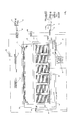
- the apparatus shown schematically in Figure 1 and 6 includes an engine 10 which generates exhaust through a discharge duct 11 for supplying the exhaust to atmosphere through an outlet 12.
- the engine concerned is primarily a stationary engine of the type used for compressing natural gas where the engine is often located in the remote location and uses as a supply fuel a stream of the natural gas itself which is intended to be compressed.
- the exhaust gases in the duct 11 are supplemented by a carbon dioxide stream from the carbon dioxide extracted from the natural gas stream using conventional processes such as amine extraction.
- the apparatus for extracting the carbon dioxide is generally indicated at 13 and includes an inlet duct 14 for taking the exhaust gases from the duct 11 and supplying them into the apparatus.
- a valve 15 is provided which closes off the duct 11 and allows all of the exhaust gases to be drawn into the apparatus described herein.
- valve 15 which acts as a bypass so as to shut off the apparatus and return the exhaust to the discharge 12 in the event that any process interruption occurs in the apparatus which would lead to a back pressure against the engine 10.
- the duct 14 is connected to a blower or fan 16 which provides all flow and pressure for the operation of the apparatus and thus avoids the back pressure on the engine 10.
- the blower can be controlled so as to maintain the pressure at the duct 11 at the required level for normal engine operation.
- the apparatus comprises a bioreactor generally indicated at 17 which is formed from a plurality of separate bio reactor vessels indicated at 18, 19, 20 and 21 respectively in Figure 1 .
- a bioreactor generally indicated at 17 which is formed from a plurality of separate bio reactor vessels indicated at 18, 19, 20 and 21 respectively in Figure 1 .
- a single vessel 18 is shown but this can be one of a plurality or can be a single vessel depending on dimensions and requirements.
- the number shown in the apparatus present is for such vessels but of course it will be appreciated that the number of vessels can vary in dependence upon the requirements for the process.
- the vessels can be used in series as shown in Figure 1 or can be used in parallel so that the cooled exhaust gas stream is split into separate pars to be fed to separate ones of the vessels.
- the bioreactor utilizes a photo-synthetic organism such as algae.
- a photo-synthetic organism such as algae.
- Such organisms are well known and commercially available and can be selected for use in generating various output materials such as fuels after the algae are harvested.
- the algae be selected for production of bio-diesel since such algae are readily available and are of a type which can be readily managed in a bio reactor of the type described hereinafter.
- the apparatus further includes a heat exchanger 22 which receives the exhaust from the blower 16 and produces from that exhaust a stream of the gas indicated at 23 and a heat stream provided on a supply duct 24.
- the heat stream may be carried by any fluid so that the heat can be used in various parts of the process.
- the heat stream is utilized for supplying heat to each of the vessels 18, 19, 20 and 21 so as to maintain each vessel at a required temperature for growing the organisms within the liquid within the vessel.
- a heat control system is schematically indicated at 25 which controls the supply of the heat to the individual vessels bearing in mind that the vessels will have different heat requirements due to the different processing conditions within each of the vessels.
- the heat control system therefore supplies the heated fluid to each of the vessels through a separate supply line and suitable monitoring systems are provided within the vessels to ensure the required temperature is maintained and the necessary control signals are transmitted back to the control system 25.
- control system 25 may also be arranged to control the supply of heat to the individual vessel so as to act to transfer heat from one vessel to another.
- cooling is also necessary so that a cooling system 26 can be provided as an optional element which provides cooling fluid to the individual vessels again controlled by the control system 25.
- the heating fluid is supplied to heating pipes 27 shown schematically and located within the vessels so that the fluid is not in contact with the materials within the vessel but merely acts to supply heat.
- the vessels contain illumination systems including lights 28 located within the vessels.
- the intention is that the vessels receive wholly generated light without any intention to receive natural light or to transmit that natural light into the growing medium within the vessel.
- the lights can be LED or fluorescent tubes which are arranged in an array described hereinafter to provide suitable illumination into the liquid medium within the vessels to provide a growing action for the organisms within the medium.
- the lights 28 are powered by an electric supply 29 taken from the site electricity supply.
- the system utilizing the site electricity supply is more simple and more suitable without adding the complexity of adding electricity manufacture on site. However this possibility is shown in Figure 6 and described in more detail hereinafter.
- each vessel contains a bath of a liquid medium, generally water at a required pH.
- the liquid medium is maintained at the required temperature and at the required pH by carefully monitoring the temperature and pH at various locations within the vessel to ensure that the organisms are maintained within the optimum growing conditions at all places within the vessel.
- each of the vessels has its own liquid and its own liquid processing and operating system.
- the liquid for the vessel 21 is injected at an inlet location 30 of the vessel and is extracted at an outlet 31.
- the liquid is then recirculated back to the inlet through a processing system schematically indicated at 32.
- each of the vessels 18, 19 and 20 contains the same processing system schematically indicated at 32.
- the processing system is shown in more detail in respect of vessel 18.
- the processing system 32 of the vessel 18 includes a duct 33 supplying the extracted liquid containing the organisms at their end of their process within the vessel so that the liquid is carried to an algae separation system schematically indicated at 34.
- the vessel is arranged so that the passage of the liquid medium through the vessel carries out a growing action on the organism so that the percentage of the algae within the liquid medium increases from the input 30 at a value of the order of 3% through to the outlet 31 where the value is of the order of 6%.
- the algae be introduced to vessel at a lower level with the ability to reproduce within the vessel to a level which is generally the maximum that can be obtained within the illumination system so that the difference between the maximum and minimum levels can be extracted by the algae separation systems 34, returning the minimum level to the vessel for a further passage through the vessel in a further cycle.
- the system is continuous in that the medium contained minimum level of algae is introduced continuously into the vessel and is extracted continuously at the outlet so that the content of algae gradually increases as the medium passes through the vessel in a in a path to the outlet.
- Various techniques for separation of the algae are well known and can be used from commercial systems generally including centrifuge systems which in effect increase the concentration of the algae within the liquid medium and extract the portion of increased concentration leaving the remaining portion to be returned.
- the extracted materials contains a proportion of the liquid medium which is then extracted for return to the system or is expelled in a dewatering system generally indicated at 35.
- the dewatering system 35 can use heat from the exchanger 22 carried along a line 36 to a dewatering system. Suitable dewatering systems are commercially available.
- the extracted algae and concentration are supplied to a processor 37 again which is of a conventional nature which is used to process the algae to produce a fuel in a fuel supply 38.
- a processor 37 again which is of a conventional nature which is used to process the algae to produce a fuel in a fuel supply 38.
- the algae selected produces bio-diesel.
- the extracted liquid medium containing the minimum amount of algae is returned to the inlet 30 but is passed through a processing step indicated at 39 where the inlet materials are analyzed and the necessary additives supplied to the materials to ensure that the liquid medium contains the required levels of algae and required levels of further materials when introduced at the inlet 30. For this reason there is provided an algae supply 40 and a nutrient supply 41 which supplies the required materials to the step 39. Thus when the material is added into the vessel they are at the required levels for nutrient, pH and algae content.
- the exhaust gas on the line 23 is passed through each of the vessels in turn so that they are arranged in series relative to the gas supply.
- the supply line 23 supplies a gas inlet 42 which enters the vessel 21.
- the gas is extracted at an outlet 43 which is then transferred to the inlet of the vessel through a pump 43A.
- the gas passes, in the arrangement of Figure 1 , through each of the vessels in turn thus emerging from the vessel 18 finally after the final processing step where the gas is supplied to a discharge duct 44 where the gas is released to atmosphere at 45. It will be appreciated therefore that the amount of carbon dioxide within the gas decreases as it enters and passes through each vessel.
- the parameters within the vessels are therefore selected independently of one another so as to maximize the processing of the materials within the respective vessel. It will be appreciated therefore that the amount of CO2 within the last vessel 18 is significantly reduced relative to the first vessel 21. For this reason the dwell time of the liquid and the algae within the vessel 18 must be significantly greater than the dwell time within the vessel 21. For this reason the flow rate through the vessel can be significantly higher in the vessel 21 than in the vessel 18.
- the vessels may be of different sizes. In each case the intention is to ensure that the growth of the algae is optimized within the vessel so that the algae levels enter at the predetermined minimum level and exit at the required elevated level.
- a further processing characteristic which can be adjusted within the individual vessels is that of a recirculation system generally indicated at 46.
- each of the vessels has a recirculation system for the gas so that the gas is returned into the vessel for recirculation.
- the proportion which is recirculated can be controlled so that the number of recirculation's is controlled and can be varied to manage the system within the bio-reactor.
- the vessel comprises a rectangular container with four side walls 50 upstanding from a base and covered by a top cover 51. Each of the walls and the top cover are insulated by an insulating material 52 so as to maintain heat within the vessel. It is expected that these vessels will be operating in low temperature environments so that there will be a requirement for additional heat rather than cooling.
- divider walls 53, 54, 55 and 56 Inside the outer walls, there are provided a series of divider walls 53, 54, 55 and 56. These are arranged so that the walls 53 and 55 extend from one end wall and are spaced from the other end wall and symmetrically the dividers 54 and 56 extend from the other end wall and extend back toward the first end wall from which they are spaced. This forms a labyrinthine path from the liquid inlet 30 to the liquid outlet 31.
- Each divider is formed from a pair of transparent sheets 57 and 58 which form between them a space 59 separated from the liquid within the vessel and flowing through the labyrinth dine path.
- a plurality of fluorescent tubes 60 which extend from an upper connector bar 61 to a lower connector bar 62 so that the fluorescent tubes extend through the full height of the bath with the bar 62 closely adjacent the base 63 of the vessel and the bar 61 just below the top of the divider walls.
- the divider walls terminate at a position spaced from the top panel 51 to leave a header space 64 above the divider walls.
- the liquid level 66 is maintained of course below the top of the divider walls.
- the fluorescent tubes 60 are maintained in a liquid free area to avoid interference with their operation.
- the path defined inside the vessel is therefore generally rectangular defined by the side walls of the vessel and the divider walls without any complexity of the light tubes and therefore can be readily cleaned by a scraping system which can pass through the path.
- the liquid therefore passes from the inlet 30 to the outlet 31 at a rate determined by the rate of flow of the liquid as it is pumped through the path and through the return system including the processor 32.
- the gas from the exhaust is introduced into the liquid within the vessel through a gas injection system schematically indicated by the gas inlet 42.
- a gas injection system schematically indicated by the gas inlet 42.
- Each of the pipe 72 extends therefore along the path portion defined between the outside wall and the first divider wall or between the divider walls themselves. In the arrangement shown where there are four divider walls, there are therefore five individual paths and five pipes 72.
- the pipes 72 are located at the base or under the base as supply ducts. On each pipe is provided an injector 73, 74.
- the injectors 74 are ceramic diffusers arranged to generate bubbles in the gas as it escapes from the pipe into the liquid. Porous ceramic diffusers thus carry the gases and divide the gases into individual small streams to generate small bubbles within the liquid.
- the directional diffusers 74 are arranged at an angle inclined to the base in a direction along the path portion tending to carry the liquid in the required direction along the path.
- each inclined diffuser includes an end face 75 where the gases emerge in a stream 76 of bubbles which is inclined along the path and also rises within the liquid as indicated at 77. This acts to generate a stream of small bubbles within the liquid and at the same time acts to cause slight agitation within the liquid and slight flow of the liquid along the path.
- the amount of injection is maintained so that the turbulence within the liquid is below a level which can damage the algae. It will be appreciated that turbulence above certain levels causes a shearing action within the structure of the algae which can break the cells and thus interfere with the proper growth.
- the provision of the directional diffusers provides a mixing of the bubbles to maximize the dissolving of the carbon dioxide into the liquid and the integration of the carbon dioxide with the algae for the photosynthesis to occur which leads to the growth.
- a gas extraction system for the recirculation including a plurality of extraction pipes 75 extending across the header space 64 and providing a series of inlet openings 76 along those pipes.
- the pipes connect at one end to a common discharge pipe 77 carrying the extracted gas to an exterior transfer pipe 78 to a blower 79 and a valve 80 which controls the amount of gas extracted through the recirculation system.
- the gas in the recirculation system is returned to the inlet 42 which is then re-injected through the system 70.
- the gas outlet 43 can be provided as part of the recirculation system or can be provided by a separate gas extraction pipe which draws gas from the vessel at a rate equal to the gas inlet supply rate.
- the CO2 content of the gas at the inlet 42 and at the outlet 43 is measured by a sensor 42A, 43A for managing the process within the respective vessel.
- the CO2 content can be used to control various parameters including particularly the volume recirculated through the respective vessel.
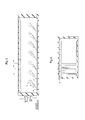
- the vessel 18 defining the bioreactor cell is single vessel defined by a base 181, upstanding end walls 182 and 183 and upstanding side walls 184 and 185 forming a rectangular container of simple construction. There is therefore merely a common hollow interior with no pathways of separate chambers.
- the system operates to directly apply the exhaust gases to the liquid medium after cooling to a temperature which avoids overheating the liquid.
- This is possible particularly in view of the use of natural gas as a fossil fuel, bearing in mind that combustion of natural gas generates much lower levels of toxic materials than do other fuels.
- the application of the un-processed natural gas exhaust into contact with the organisms does not cause toxic effects on the organisms allowing them to flourish in the medium to process the carbon dioxide in the gas.
- an electricity generation system 221 in the form preferably of an organic Rankin cycle engine is provided. This receives heat from the exhaust via a branch of the heat exchanger 22 to generate electric power which is then used to drive the system.
- power can be supplied to the pump 43A, the blower 16, a pump 30A driving the water supply at the inlet 30, the lighting banks 28 and the separation system 34. In this way the system can be self sufficient for energy using only the excess heat from the engine 10.
- the system shown in Figure 6 to 10 therefore provides a method for extraction of carbon dioxide from exhaust gases from combustion of a fossil fuel where the fuel is preferably used in an engine using natural gas as the supply.
- the method includes providing a supply 11 of exhaust gas from combustion of a fossil fuel in the engine 10. Heat is extracted from the exhaust gas using the heat exchanger 22 to cool the exhaust gas and to generate the supply 24 of a heated liquid.
- water vapor is extracted at 222 from the exhaust gas in the heat exchanger or at a specifically defined extraction system to form a supply of water.
- the vessel 18 contains the liquid medium including or primarily water which carries the photo-synthetic organisms. Light energy is provided by the lighting banks 28 and the cooled exhaust gas are supplied to the liquid medium in the vessel to carry out the growth of the organisms using photosynthesis.
- the organisms are extracted from the liquid medium by the extraction system 31 allowing harvesting at least some of the organisms from the extracted liquid medium at the separation system 34 and return of some of the liquid medium including some of the water after the extraction to the vessel 18.
- At least some of the supply of water 222 from the heat exchanger is supplied to the vessel via a pipe and the pump 30A to provide a make-up supply of water to replace water removed during the extracting of the organisms or by other losses.
- the amount of water which is available to be extracted from the exhaust gas is greater than the amount of water removed during the extracting of the organisms so that the system is water supply positive. This is a particular advantage where water is not available or is in short supply.
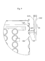
- the heating of the wall 185 of the tank 18 using the heated liquid from the heat exchanger 22 is effected by passing the liquid through at least one heating duct 241 mounted in contact with at least one wall 185 of the vessel so as to apply heat to the wall 185. More than one duct can be provided ion the wall. Only one or more than one of the walls may be heated depending on the temperature required and the temperature of the liquid, bearing in mind the necessity to maintain the required temperature of the medium without overheating.
- the duct 241 is carried on an outside surface of the wall so that it does not interfere with maintaining the inside surface of the wall flush for cleaning.
- the walls are corrugated as indicated at 186 leaving convenient hollows on the outside which can be closed by a cover 187 to define the duct to be heated.
- the duct can be filled with a suitable heat transfer liquid such as glycol to receive the heat from the hot supply pipes 242 before returning the heating liquid through the pipes 243 to the heat exchanger.
- a suitable heat transfer liquid such as glycol
- the cooled exhaust gas from the pipe 23 is supplied to the vessel 18 though the pump 43A and the pipe 42 to a plurality of diffusers 231 at the base of the vessel.
- the diffusers comprise commercially available circular ceramic disks into which the gas is introduced to release the gas into the medium as a stream of bubbles.
- the number and dimensions of the diffusers can vary according to engineering practice.
- the total area of the diffusers combined is preferably of the order of 0.00005 m2 per liter of liquid medium (0.00204 ft2 per US Gallon of liquid medium)
- the gas is supplied to the diffusers through a plurality of communication conduits 232 passing through the medium in the vessel and connected to the pipe 42 at one end of the vessel.
- the conduits form an array of pipes located in the medium at the bottom of the vessel and include heat transfer fins or the like to assist in transferring heat from the gas to the medium.
- the communication conduits or pipe array 232 is arranged to act as a heat exchanger transferring heat from the gas to the medium in the vessel. This heat transfer allows the gas to enter the vessel at a higher temperature than would otherwise be possible since the gas is further cooled before it is released into the medium through the diffusers. This reduces the heat transfer capacity required for the heat exchanger 22 and improves heat transfer efficiency.
- the use of the heating through the tank wall and the heat exchange at the bottom of the vessel by the supply pipes ensures effective heat transfer to keep the medium at the required temperatures even in the coldest climate while avoiding hot spots or overheating of the medium.
- the heat supplied by the cooled exhaust gas and by the heating liquid is controlled to maintain the temperature of the medium in the vessel at a temperature for active growth of the organisms.
- the supply construction 232 is defined by a horizontal array of supply pipes extending across the base of the vessel.
- the liquid medium is extracted by a suction system 311 extending across the base underneath the supply construction and connected to the duct 31.
- the suction system includes an array of outlet openings so that the extraction occurs across the whole area of the base to ensure continual extraction of any materials such as particulates collecting at the base.
- the suction system comprises a plurality of transversely extending ducts 312 at spaced positions along the length of the vessel and each defining an upwardly facing slot 313 across the base.
- the transverse ducts are connected to a longitudinal pipe 314 along the center of the vessel. For occasional cleaning at a shut down, there is provided a sump 315 in the base 181.
- Such light and dark cycles are created by the simple expedient of turning the illumination source on and off at suitable periods which can be measured in hours or parts of seconds.
- the required light and dark cycles are generated by forming a lighted area 281 in the vessel in which the medium is supplied with light energy and a dark area 282 in the vessel in which the medium is remote from the light energy.
- the medium containing the organisms is then circulated between the light and dark areas to generate the light and dark cycles for the organisms.
- the lighted area is formed by a series of light banks 283 in the vessel extending from the top 186 to a bottom 284 of the light banks spaced from the base 181.
- the density of the organisms in the medium is such that the light can only penetrate from a source such as a florescent tube to a depth of the order of a few inches at most. Thus as soon as the organisms move beyond this distance from the light source they are in the dark area.
- the ratio of light area to total area in the vessel is typically in the range 50 to 80% which simulates the level of light which the organism might meet in normal existence in the day to night light cycle, thus maximizing the growth potential while avoiding the over stimulation of the organisms which interferes with growth.
- the lighted and dark areas are open to one another at the bottom of the light banks within the vessel.
- the interface between the lighted and dark areas is formed by an end face of the banks of light sources without any impediment to flow therebetween.
- the circulation between the areas is caused by free currents within the vessel generated by circulation fans 285 and 286 located suitable within the vessel.
- the fans are located at the bottom corners within the dark area of the vessel to generate complex flow and turbulence within the vessel.
- These fans are supplemented by additional fans between one bank 283 and the next and tending to carry the medium though the banks.
- the circulation is effected without a pathway or guide which defines a specific path of the medium and the medium is free to move within the vessel.
- the light sources are arranged at spacing to provide light to substantially all of the organisms in the lighted area.
- the dark area all the organisms are dark.
- the individual organisms may see very different ratios of light and dark even though the average will see a ratio of light and dark equal to the ratio of volume in the light and dark areas.
- the organisms are themselves are not average or homogenous and vary in their characteristics and requirements depending on their stage of life.
- the rate of circulation can be varied to maximize the growth rate of the organisms either by changing the flow patterns by redirecting the circulation fans of by increasing the number or flow rate of the fans.
- the light energy is supplied by the plurality of banks 283 of light sources which are suspended into the vessel from supports at the top.
- Each bank comprise a series of rows side by side across the vessel.
- Each row includes a plurality of parallel spaced florescent tubes 288 carried on a common mounting assembly 289 defined by vertical side rails 290 and 291.
- a top housing 292 contains the electrical components and supports the rails.
- the row is dropped into the vessel from the top and sits on a pair of wires 293 across the opening so that the wires support all the rows of the bank.
- Each florescent tube is surrounded by a protecting sleeve 295 which allows cleaning of the light system to ensure continued light penetration.
- the tubes of each row are horizontal and the rows are vertical and arranged side by side across the vessel with each row extending longitudinally of the vessel.
- the banks of light sources can be removed from the vessel through the top. This leaves the internal surface of the walls free from any mounting for the lighting system.
- the supply construction 232 and the diffusers 231 can be removed through the top by disconnecting the end of the array from the pipe 42.
- the upstanding side walls are flush with no outstanding components allowing cleaning of the upstanding flush side walls.
- suction system 311 including the ducts 312 and the pipe 313 can be removed through the top by disconnecting the end of the array from the pipe.
- the upstanding side walls and base are flush with no outstanding components allowing cleaning of the upstanding flush side walls.
Landscapes
- Engineering & Computer Science (AREA)
- Chemical & Material Sciences (AREA)
- Health & Medical Sciences (AREA)
- Life Sciences & Earth Sciences (AREA)
- Bioinformatics & Cheminformatics (AREA)
- Organic Chemistry (AREA)
- Wood Science & Technology (AREA)
- Zoology (AREA)
- Biomedical Technology (AREA)
- Biotechnology (AREA)
- Genetics & Genomics (AREA)
- General Engineering & Computer Science (AREA)
- Biochemistry (AREA)
- General Health & Medical Sciences (AREA)
- Sustainable Development (AREA)
- Microbiology (AREA)
- Molecular Biology (AREA)
- Analytical Chemistry (AREA)
- Environmental & Geological Engineering (AREA)
- Combustion & Propulsion (AREA)
- General Chemical & Material Sciences (AREA)
- Oil, Petroleum & Natural Gas (AREA)
- Chemical Kinetics & Catalysis (AREA)
- Apparatus Associated With Microorganisms And Enzymes (AREA)
- Treating Waste Gases (AREA)
Applications Claiming Priority (2)
| Application Number | Priority Date | Filing Date | Title |
|---|---|---|---|
| US12/869,398 US20110020916A1 (en) | 2008-04-30 | 2010-08-26 | Extraction of CO2 Gas |
| US12/869,376 US20110020915A1 (en) | 2008-04-30 | 2010-08-26 | Extraction of CO2 Gas |
Publications (1)
| Publication Number | Publication Date |
|---|---|
| EP2422870A1 true EP2422870A1 (de) | 2012-02-29 |
Family
ID=43734167
Family Applications (1)
| Application Number | Title | Priority Date | Filing Date |
|---|---|---|---|
| EP10177231A Withdrawn EP2422870A1 (de) | 2010-08-26 | 2010-09-16 | Extraktion von CO2-Gas |
Country Status (1)
| Country | Link |
|---|---|
| EP (1) | EP2422870A1 (de) |
Cited By (8)
| Publication number | Priority date | Publication date | Assignee | Title |
|---|---|---|---|---|
| WO2014063229A1 (en) * | 2012-10-24 | 2014-05-01 | Pond Biofuels Inc. | Process of operating a plurality of photobioreactors |
| US8889400B2 (en) | 2010-05-20 | 2014-11-18 | Pond Biofuels Inc. | Diluting exhaust gas being supplied to bioreactor |
| US8940520B2 (en) | 2010-05-20 | 2015-01-27 | Pond Biofuels Inc. | Process for growing biomass by modulating inputs to reaction zone based on changes to exhaust supply |
| US8969067B2 (en) | 2010-05-20 | 2015-03-03 | Pond Biofuels Inc. | Process for growing biomass by modulating supply of gas to reaction zone |
| US9534261B2 (en) | 2012-10-24 | 2017-01-03 | Pond Biofuels Inc. | Recovering off-gas from photobioreactor |
| US11124751B2 (en) | 2011-04-27 | 2021-09-21 | Pond Technologies Inc. | Supplying treated exhaust gases for effecting growth of phototrophic biomass |
| US11512278B2 (en) | 2010-05-20 | 2022-11-29 | Pond Technologies Inc. | Biomass production |
| US11612118B2 (en) | 2010-05-20 | 2023-03-28 | Pond Technologies Inc. | Biomass production |
Citations (15)
| Publication number | Priority date | Publication date | Assignee | Title |
|---|---|---|---|---|
| US5104803A (en) | 1988-03-03 | 1992-04-14 | Martek Corporation | Photobioreactor |
| US5659977A (en) | 1996-04-29 | 1997-08-26 | Cyanotech Corporation | Integrated microalgae production and electricity cogeneration |
| US5741702A (en) | 1995-06-21 | 1998-04-21 | Lorenz; Thomas | System for processing gases containing carbon dioxide |
| US5804432A (en) | 1992-06-18 | 1998-09-08 | Knapp; Doug | Method and apparatus for treating contaminated water |
| US6083740A (en) | 1998-02-12 | 2000-07-04 | Spirulina Biological Lab., Ltd. | System for purifying a polluted air by using algae |
| US6287852B1 (en) | 1997-10-17 | 2001-09-11 | Matsushita Electric Industrial Co., Ltd. | Photosynthetic culture apparatus and group of photosynthesis culture apparatuses |
| US20030059932A1 (en) | 2001-07-23 | 2003-03-27 | National Research Council Of Canada | Photobioreactor |
| US20030073231A1 (en) * | 2001-10-17 | 2003-04-17 | Co2 Solution Inc. | Photobioreactor |
| US6667171B2 (en) | 2000-07-18 | 2003-12-23 | Ohio University | Enhanced practical photosynthetic CO2 mitigation |
| WO2007011343A1 (en) | 2005-07-18 | 2007-01-25 | Greenfuel Technologies Corporation | Photobioreactor and process for biomass production and mitigation of pollutants in flue gases |
| WO2007134141A2 (en) | 2006-05-10 | 2007-11-22 | Ohio University | Apparatus and method for growing biological organisms for fuel and other purposes |
| WO2008008262A2 (en) | 2006-07-10 | 2008-01-17 | Greenfuel Technologies Corp. | Photobioreactor systems and methods for treating co2-enriched gas and producing biomass |
| US20090275120A1 (en) * | 2008-04-30 | 2009-11-05 | Edward John Koch | Extraction of co2 gas from engine exhaust |
| WO2010025345A2 (en) * | 2008-08-28 | 2010-03-04 | Innovative American Technology Inc. | Semi-closed loop alga-diesel fuel photobioreactor using waste water |
| WO2010076795A1 (en) * | 2009-01-02 | 2010-07-08 | Avraham Avidan | Non-flat photobioreactor |
-
2010
- 2010-09-16 EP EP10177231A patent/EP2422870A1/de not_active Withdrawn
Patent Citations (16)
| Publication number | Priority date | Publication date | Assignee | Title |
|---|---|---|---|---|
| US5104803A (en) | 1988-03-03 | 1992-04-14 | Martek Corporation | Photobioreactor |
| US5804432A (en) | 1992-06-18 | 1998-09-08 | Knapp; Doug | Method and apparatus for treating contaminated water |
| US5741702A (en) | 1995-06-21 | 1998-04-21 | Lorenz; Thomas | System for processing gases containing carbon dioxide |
| US5659977A (en) | 1996-04-29 | 1997-08-26 | Cyanotech Corporation | Integrated microalgae production and electricity cogeneration |
| US6287852B1 (en) | 1997-10-17 | 2001-09-11 | Matsushita Electric Industrial Co., Ltd. | Photosynthetic culture apparatus and group of photosynthesis culture apparatuses |
| US6083740A (en) | 1998-02-12 | 2000-07-04 | Spirulina Biological Lab., Ltd. | System for purifying a polluted air by using algae |
| US6667171B2 (en) | 2000-07-18 | 2003-12-23 | Ohio University | Enhanced practical photosynthetic CO2 mitigation |
| US20030059932A1 (en) | 2001-07-23 | 2003-03-27 | National Research Council Of Canada | Photobioreactor |
| US6602703B2 (en) | 2001-10-17 | 2003-08-05 | Co2 Solution Inc. | Photobioreactor |
| US20030073231A1 (en) * | 2001-10-17 | 2003-04-17 | Co2 Solution Inc. | Photobioreactor |
| WO2007011343A1 (en) | 2005-07-18 | 2007-01-25 | Greenfuel Technologies Corporation | Photobioreactor and process for biomass production and mitigation of pollutants in flue gases |
| WO2007134141A2 (en) | 2006-05-10 | 2007-11-22 | Ohio University | Apparatus and method for growing biological organisms for fuel and other purposes |
| WO2008008262A2 (en) | 2006-07-10 | 2008-01-17 | Greenfuel Technologies Corp. | Photobioreactor systems and methods for treating co2-enriched gas and producing biomass |
| US20090275120A1 (en) * | 2008-04-30 | 2009-11-05 | Edward John Koch | Extraction of co2 gas from engine exhaust |
| WO2010025345A2 (en) * | 2008-08-28 | 2010-03-04 | Innovative American Technology Inc. | Semi-closed loop alga-diesel fuel photobioreactor using waste water |
| WO2010076795A1 (en) * | 2009-01-02 | 2010-07-08 | Avraham Avidan | Non-flat photobioreactor |
Cited By (8)
| Publication number | Priority date | Publication date | Assignee | Title |
|---|---|---|---|---|
| US8889400B2 (en) | 2010-05-20 | 2014-11-18 | Pond Biofuels Inc. | Diluting exhaust gas being supplied to bioreactor |
| US8940520B2 (en) | 2010-05-20 | 2015-01-27 | Pond Biofuels Inc. | Process for growing biomass by modulating inputs to reaction zone based on changes to exhaust supply |
| US8969067B2 (en) | 2010-05-20 | 2015-03-03 | Pond Biofuels Inc. | Process for growing biomass by modulating supply of gas to reaction zone |
| US11512278B2 (en) | 2010-05-20 | 2022-11-29 | Pond Technologies Inc. | Biomass production |
| US11612118B2 (en) | 2010-05-20 | 2023-03-28 | Pond Technologies Inc. | Biomass production |
| US11124751B2 (en) | 2011-04-27 | 2021-09-21 | Pond Technologies Inc. | Supplying treated exhaust gases for effecting growth of phototrophic biomass |
| WO2014063229A1 (en) * | 2012-10-24 | 2014-05-01 | Pond Biofuels Inc. | Process of operating a plurality of photobioreactors |
| US9534261B2 (en) | 2012-10-24 | 2017-01-03 | Pond Biofuels Inc. | Recovering off-gas from photobioreactor |
Similar Documents
| Publication | Publication Date | Title |
|---|---|---|
| US20090275120A1 (en) | Extraction of co2 gas from engine exhaust | |
| EP2422870A1 (de) | Extraktion von CO2-Gas | |
| CA2712862C (en) | Photobioreactor and method for processing polluted air | |
| WO2008040828A1 (es) | Fotobiorreactor vertical sumergible para la obtención de biocombustibles | |
| US20120088296A1 (en) | Photobioreactor system | |
| ES2653848T3 (es) | Procedimiento en continuo para la generación de un producto de valor nutricional elevado y de recursos energéticos | |
| KR20090029264A (ko) | 이산화탄소 격리를 위한 방법 및 장치 | |
| US20160017266A1 (en) | Photobioreactor and Method for Processing Polluted Air | |
| US10123495B2 (en) | Controlled system for supporting algae growth with adsorbed carbon dioxide | |
| WO2012024758A1 (en) | Extraction of co2 gas | |
| US20110020916A1 (en) | Extraction of CO2 Gas | |
| US9206388B1 (en) | Process for a sustainable growth of algae in a bioreactor and for the extraction of a biofuel product | |
| CN103946368A (zh) | 利用废气使光养生物质生长的方法 | |
| CA2630297C (en) | Extraction of co2 gas from engine exhaust | |
| CA2780103A1 (en) | Growing microorganisms using exhaust gas as a nutrient supply | |
| US20150315534A1 (en) | Enhanced Photobioreactor System | |
| TWI433647B (zh) | 微藻養殖模組 | |
| WO2007144440A1 (es) | Fotoconvertidor de energía para la obtención de biocombustibles | |
| LU102994B1 (en) | Cultivating aquatic organisms, such as algae, in particular to support the conversion of co2 into biomass | |
| WO2013112961A1 (en) | Fluid treatment system | |
| CA2713240C (en) | Extraction of c02 gas | |
| US20110020915A1 (en) | Extraction of CO2 Gas | |
| US9090862B2 (en) | System and method for processing biological material | |
| US10400202B2 (en) | Enhanced photobioreactor system | |
| CN223921382U (zh) | 一种藻光互补的微藻养殖系统 |
Legal Events
| Date | Code | Title | Description |
|---|---|---|---|
| AK | Designated contracting states |
Kind code of ref document: A1 Designated state(s): AL AT BE BG CH CY CZ DE DK EE ES FI FR GB GR HR HU IE IS IT LI LT LU LV MC MK MT NL NO PL PT RO SE SI SK SM TR |
|
| AX | Request for extension of the european patent |
Extension state: BA ME RS |
|
| PUAI | Public reference made under article 153(3) epc to a published international application that has entered the european phase |
Free format text: ORIGINAL CODE: 0009012 |
|
| RTI1 | Title (correction) |
Free format text: EXTRACTION OF CO2 GAS |
|
| 17P | Request for examination filed |
Effective date: 20120828 |
|
| STAA | Information on the status of an ep patent application or granted ep patent |
Free format text: STATUS: THE APPLICATION IS DEEMED TO BE WITHDRAWN |
|
| 18D | Application deemed to be withdrawn |
Effective date: 20120830 |