EP2423048A2 - Lichtverteilungssteuervorrichtung - Google Patents
Lichtverteilungssteuervorrichtung Download PDFInfo
- Publication number
- EP2423048A2 EP2423048A2 EP11178951A EP11178951A EP2423048A2 EP 2423048 A2 EP2423048 A2 EP 2423048A2 EP 11178951 A EP11178951 A EP 11178951A EP 11178951 A EP11178951 A EP 11178951A EP 2423048 A2 EP2423048 A2 EP 2423048A2
- Authority
- EP
- European Patent Office
- Prior art keywords
- lane mark
- lane
- light distribution
- sensing mode
- steering angle
- Prior art date
- Legal status (The legal status is an assumption and is not a legal conclusion. Google has not performed a legal analysis and makes no representation as to the accuracy of the status listed.)
- Granted
Links
- 238000005286 illumination Methods 0.000 claims abstract description 18
- 238000005516 engineering process Methods 0.000 description 2
- 206010016322 Feeling abnormal Diseases 0.000 description 1
- 230000002159 abnormal effect Effects 0.000 description 1
- 230000002542 deteriorative effect Effects 0.000 description 1
- 230000007613 environmental effect Effects 0.000 description 1
- 238000000034 method Methods 0.000 description 1
- 230000003287 optical effect Effects 0.000 description 1
Images




Classifications
-
- B—PERFORMING OPERATIONS; TRANSPORTING
- B60—VEHICLES IN GENERAL
- B60Q—ARRANGEMENT OF SIGNALLING OR LIGHTING DEVICES, THE MOUNTING OR SUPPORTING THEREOF OR CIRCUITS THEREFOR, FOR VEHICLES IN GENERAL
- B60Q1/00—Arrangement of optical signalling or lighting devices, the mounting or supporting thereof or circuits therefor
- B60Q1/02—Arrangement of optical signalling or lighting devices, the mounting or supporting thereof or circuits therefor the devices being primarily intended to illuminate the way ahead or to illuminate other areas of way or environments
- B60Q1/04—Arrangement of optical signalling or lighting devices, the mounting or supporting thereof or circuits therefor the devices being primarily intended to illuminate the way ahead or to illuminate other areas of way or environments the devices being headlights
- B60Q1/06—Arrangement of optical signalling or lighting devices, the mounting or supporting thereof or circuits therefor the devices being primarily intended to illuminate the way ahead or to illuminate other areas of way or environments the devices being headlights adjustable, e.g. remotely-controlled from inside vehicle
- B60Q1/08—Arrangement of optical signalling or lighting devices, the mounting or supporting thereof or circuits therefor the devices being primarily intended to illuminate the way ahead or to illuminate other areas of way or environments the devices being headlights adjustable, e.g. remotely-controlled from inside vehicle automatically
- B60Q1/085—Arrangement of optical signalling or lighting devices, the mounting or supporting thereof or circuits therefor the devices being primarily intended to illuminate the way ahead or to illuminate other areas of way or environments the devices being headlights adjustable, e.g. remotely-controlled from inside vehicle automatically due to special conditions, e.g. adverse weather, type of road, badly illuminated road signs or potential dangers
-
- B—PERFORMING OPERATIONS; TRANSPORTING
- B60—VEHICLES IN GENERAL
- B60Q—ARRANGEMENT OF SIGNALLING OR LIGHTING DEVICES, THE MOUNTING OR SUPPORTING THEREOF OR CIRCUITS THEREFOR, FOR VEHICLES IN GENERAL
- B60Q1/00—Arrangement of optical signalling or lighting devices, the mounting or supporting thereof or circuits therefor
- B60Q1/02—Arrangement of optical signalling or lighting devices, the mounting or supporting thereof or circuits therefor the devices being primarily intended to illuminate the way ahead or to illuminate other areas of way or environments
- B60Q1/04—Arrangement of optical signalling or lighting devices, the mounting or supporting thereof or circuits therefor the devices being primarily intended to illuminate the way ahead or to illuminate other areas of way or environments the devices being headlights
- B60Q1/06—Arrangement of optical signalling or lighting devices, the mounting or supporting thereof or circuits therefor the devices being primarily intended to illuminate the way ahead or to illuminate other areas of way or environments the devices being headlights adjustable, e.g. remotely-controlled from inside vehicle
- B60Q1/08—Arrangement of optical signalling or lighting devices, the mounting or supporting thereof or circuits therefor the devices being primarily intended to illuminate the way ahead or to illuminate other areas of way or environments the devices being headlights adjustable, e.g. remotely-controlled from inside vehicle automatically
- B60Q1/12—Arrangement of optical signalling or lighting devices, the mounting or supporting thereof or circuits therefor the devices being primarily intended to illuminate the way ahead or to illuminate other areas of way or environments the devices being headlights adjustable, e.g. remotely-controlled from inside vehicle automatically due to steering position
-
- B—PERFORMING OPERATIONS; TRANSPORTING
- B60—VEHICLES IN GENERAL
- B60Q—ARRANGEMENT OF SIGNALLING OR LIGHTING DEVICES, THE MOUNTING OR SUPPORTING THEREOF OR CIRCUITS THEREFOR, FOR VEHICLES IN GENERAL
- B60Q2300/00—Indexing codes for automatically adjustable headlamps or automatically dimmable headlamps
- B60Q2300/10—Indexing codes relating to particular vehicle conditions
- B60Q2300/12—Steering parameters
- B60Q2300/122—Steering angle
-
- B—PERFORMING OPERATIONS; TRANSPORTING
- B60—VEHICLES IN GENERAL
- B60Q—ARRANGEMENT OF SIGNALLING OR LIGHTING DEVICES, THE MOUNTING OR SUPPORTING THEREOF OR CIRCUITS THEREFOR, FOR VEHICLES IN GENERAL
- B60Q2300/00—Indexing codes for automatically adjustable headlamps or automatically dimmable headlamps
- B60Q2300/30—Indexing codes relating to the vehicle environment
- B60Q2300/32—Road surface or travel path
- B60Q2300/322—Road curvature
Definitions
- An Apparatus consistent with the present invention relates to a light distribution control apparatus which controls the distribution of the light of a headlamp or the like for illuminating an area ahead of a vehicle such as a car.
- an apparatus consistent with the invention relates to a light distribution control apparatus for automatically controlling the light distribution.
- a steering angle sensing mode which controls the illumination direction (illumination optical axis direction) of the light of the headlamp according to a steering angle signal to be obtained by following the angle of steering of the car.
- a lane mark sensing mode which detects the lines of both sides (vehicle lines which are hereinafter referred to as lane marks) of a running passage of the driver's own vehicle from an image obtained when picking up an area existing ahead of the vehicle, recognizes the running area of the vehicle according to the detected marks, and controls the illumination direction of the headlamp toward the thus recognized running area.
- the lane mark sensing mode even when a driver steers the steering wheel of the vehicle improperly, the running area of the vehicle can be illuminated positively. Thanks to this, the lane mark sensing mode is more preferable than the steering angle sensing mode from the viewpoint of safe running.
- the light distribution control according to the lane mark sensing mode disclosed in the reference patent 1 in the case that the lane marks are detected, it is possible to realize a suitable light distribution control.
- the reference patent 1 there is no description as to a case where the lane marks cannot be detected.
- measures are taken to fix the light distribution in the straight-going direction or to fix the light distribution to a direction in which the light distribution has been set before.
- the automatic light distribution control can be stopped suddenly, which gives the driver a strange feeling.
- proper light distribution control is hard to be carried out, which is not preferable from the viewpoint of safe running.
- Exemplary embodiments of the invention provide a light distribution control apparatus which, even when lane marks cannot be detected, does not give a driver a strange feeling from the light distribution but also can secure light distribution control suitable for safe running.
- the light distribution control unit may control the light distribution of the headlamp according to the lane mark sensing mode.
- the lane mark detecting unit may detect the lane marks based on an image obtained when an area ahead of a driver's own vehicle is picked up, and the light distribution control unit may control the illumination direction of the headlamp of the driver's own vehicle in the right and left direction.
- a light distribution control apparatus when the lane mark recognition rate, which express the degree of reliability of the detected lane marks, is high, the light distribution control is carried out according to the lane mark sensing mode and, when the lane mark recognition rate is lower and thus the degree of reliability of the detected lane marks is lower, the light distribution control is carried out according to the steering angle sensing mode. Specifically, when the lane marks cannot be properly detected, light distribution control is carried based on the steering angle. This can prevent the driver from receiving a strange feeling from the light distribution and also can enhance the visibility of the area ahead of own vehicle to thereby be able to secure light distribution control suitable for safety running.
- the light distribution control is carried out while switching the lane mark sensing mode and steering angle sensing mode over to each other according to the lane mark information about a straight road or a curved road obtained from the lane marks detected, it is possible to secure proper light distribution control corresponding to variations in the running condition of the vehicle, thereby being able to secure the safety running of the vehicle.
- an area ahead of the curved road can be illuminated regardless of steering angles when the vehicle is running along the S-shaped curved road. This can enhance the visibility of the area ahead of the vehicle while running and thus can secure the safety running of the vehicle.
- FIG. 1 is a conceptual structure view of an embodiment in which the invention is applied to a light distribution control apparatus of a headlamp used in a car.
- a car "CAR" includes a headlamp (headlight) HL for illuminating a road area ahead of the driver's own car (area ahead), and a swivel control unit 1 serving as a light distribution control unit according to the invention which is used to control deflection of the light distribution of the headlamp, here, the light illumination direction of the headlamp in the right and left direction.
- the car “CAR” further includes an image pickup camera CAM for picking up the image of the area ahead of the car, and a lane mark detecting unit 2 for detecting lane marks existing in the area ahead according to an image picked up by the image pickup camera CAM.
- the lane mark detecting unit 2 generates lane mark information showing the state of a road, that is, whether a road determined by lane marks detected is a straight road or a curved road and the rate of recognition of the lane marks detected, and then outputs the thus generated lane mark information and lane mark recognition rate to the swivel control unit 1.
- the car “CAR” includes a steering angle sensor S ⁇ for detecting the steering angle of a steering wheel to be steered by a driver, whereby the detected steering angle can be output to the swivel control unit 1.
- the headlamp HL is structured as a so called swivel lamp. Specifically, while only the conceptual structure thereof is shown in Fig. 1 , the headlamp HL can swivel a lamp unit (not shown) provided within the headlamp HL right and left using a swivel mechanism 3 attached to the headlamp HL, thereby being able to control deflection of the light illumination direction.
- the image pickup camera CAM can be constituted of a digital camera including an image pickup element which is conventionally proposed.
- the image pickup camera CAM is constituted of a digital camera using a CCD image pickup element or a MOS image pickup element which outputs an image signal corresponding to an image picked up.
- the lane mark detecting unit 2 includes a lane mark detecting portion 21 for detecting lane marks obtained from an image picked up by the image pickup camera CAM, and a lane mark recognition rate determining portion 22 for determining a lane mark recognition rate which may also be referred to as the degree of reliability that the detected lane marks are actual lane marks.
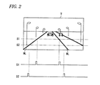
- the lane mark detecting portion 21, for example, as shown in Fig. 2 is used to detect high radiance points from scan signals S1, S2, ... obtained by scanning an image V picked up by the image pickup camera CAM at a large number of vertical positions in the horizontal direction, and then to detect, as lane marks WL, virtual lines respectively connecting together the high radiance points on the respective horizontal scan lines.
- a pair or more of high radiance points are detected and, in the case that, as shown in Fig. 3A , any of these high radiance points are present within a preset area A, the corresponding lines are detected as the lane marks WL.
- the distance D in the horizontal direction between a pair of right and left high radiance points of assumed lane marks WL is measured and, in the case that the measured distance is within a given distance error range, the assumed lines are detected as the lane marks WL.
- the given distance D is previously set according to the angle of view of the image pickup camera CAM, the distance from the image pickup camera CAM to the road surface, and the ordinary spacing between lane marks (traffic lanes width).
- the given distance varies according to the vertical positions of the same horizontal scan line of the image.
- Fig. 3B shows that, the higher the portions of the image are, the more distant they are from the own vehicle, that is, the shorter the given distance becomes.
- the lane mark detecting portion 21 detects a center point C in the right and left direction on the horizontal scan line of the detected two lane marks WL, and simulates a center line CL defined by continuously connecting together multiple center points C in the vertical direction of the image. Further, when the virtual center line CL is a straight line in the vertical direction, the lane mark detecting portion 21 determines that the current road is a straight road and when the vertical center line CL is a curved line, which is curved right or left, the portion 21 determines that the current road is a curved road. As shown in Fig.
- the portion 21 determines that the current road is an S-shaped curved road.
- the portion 21 outputs lane mark information about a straight road, curved road, S-shaped curved road or the like.
- the lane mark recognition rate determining portion 22 determines the degree of reliability that the detected lane marks are actually lane marks. That is, the determining portion 22 determines the rate of multiple high radiance points detected from the image V as shown in Fig. 2 that exist within a preset area A as shown in Fig. 3A , and determines that the thus determined rate is the lane mark recognition rate. Alternatively, when the distance D in the horizontal direction of the paired high radiance points detected with respect to a large number of horizontal scan lines as shown in Fig. 3B exist within a given distance error range, the determining portion 22 determines that the rate of such existence is the lane mark recognition rate.
- the high radiance points are all determined to correspond to lane marks, it is determined that the lane mark recognition rate is "10"; and, when the high radiance points do not exist at all, it is determined that the lane mark recognition rate is "0".
- the lane mark recognition rate is high, the degree of reliability that the detected high radiance points are lane marks is high, whereas, when the lane mark recognition rate is low, the degree of reliability that the detected high radiance points are lane marks is low.
- the swivel control unit 1 includes a swivel control portion 11 for controlling the swivel mechanism 3 of the headlamp HL, and a recognition rate comparing portion 12 for comparing the lane mark recognition rate input therein from the lane mark detecting unit 2 with a previously set reference rate. Further, the swivel control unit 1 also includes a swivel switching portion 13 which, according to the comparison results of the recognition rate comparing portion 12, the lane mark information from the lane mark detecting unit 2 and, as will be discussed later, the steering angle of own vehicle input from a steering angle sensor S ⁇ , switches in the swivel control portion 21 between the two modes of swivel control in the swivel control portion 21.
- the two modes of swivel control include a lane mark sensing mode based on the lane mark information, and a steering angle sensing mode based on the steering angle.
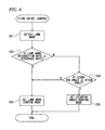
- Fig. 4 is a flow chart of first swivel control which provides the basic swivel control of a light distribution control apparatus according to an exemplary embodiment of the invention.
- the lane mark detecting portion 21 of the lane mark detecting unit 2 detects lane marks
- the lane mark recognition rate determining portion 22 determines the lane mark recognition rate and outputs lane mark information about the detected lane marks and lane mark recognition rate to the swivel control unit I (S11).
- the recognition rate comparing portion 12 of the swivel control unit 1 I compares the input lane mark recognition rate with a previously set reference rate (S 12).
- the swivel switching portion 13 sets the swivel control portion 11 to the lane mark sensing mode (S13).
- the swivel control portion 11 controls the swivel mechanism 3 according to several pieces of lane mark information simultaneously input therein, the illumination direction of the headlamp HL is swivel controlled following the detected lane marks.
- the recognition rate is lower than the reference rate when the two rates are compared by the recognition rate comparing portion 12
- the swivel switching portion 13 sets the swivel control portion 11 to the steering angle sensing mode (S 14).
- the steering angle sensing mode since the swivel control portion 11 controls the swivel mechanism 3 according to the steering angle received from the steering angle sensor S ⁇ , the illumination direction of the headlamp HL is controlled following the steering direction of the steering wheel.
- the headlamp HL is swivel controlled according to the lane marks detected, the running area of the driver's own vehicle can be illuminated positively and thus the visibility of the running area can be enhanced even when a driver is not carrying out a proper steering operation, thereby being able to secure the safe running of the own vehicle.
- the reliability of the lane marks found in the lane mark detecting unit 2 is low, there is no possibility that the illumination direction of the headlamp HL can be controlled according to the wrong lane mark information since the headlamp HL is swivel controlled according to the steering angle. Therefore, since there is no possibility that the headlamp HL can be controlled in an abnormal direction, which can prevent the driver from feeling strange in the light distribution and can also enhance the visibility of the area in the steering direction.
- the lane mark sensing mode and steering angle sensing mode can be switched between each other according to the lane mark recognition rate and is thereby able to carry out a proper swivel control operation.
- the proper swivel control is hard to be carried out depending on the curved state of the road.
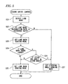
- the swivel control unit 1 compares the lane mark recognition rate obtained from the lane mark detecting unit 2 with the reference rate (S22) and, when the lane mark recognition rate is equal to or higher than the reference rate, sets the lane mark sensing mode (S23). When the lane mark recognition rate is lower than the reference rate, the steering angle sensing mode is set (S27) similarly to the first swivel control discussed above. Additionally in the lane mark sensing mode, it is further determined whether or not the lane marks are curved lines (S24) according to the lane mark information.
- the lane mark sensing mode is maintained (S25).
- the steering angle has varied by a given angle amount or more (S26).
- the lane mark sensing mode is maintained as it is (S25).
- the mode is switched to the steering angle sensing mode (S27) and, then, the swivel control is carried out based on the steering angle.
- the lane mark sensing mode when the steering angle is small, the lane mark sensing mode is set and thus the illumination direction of the headlamp HL is swivel controlled in a direction along the curved road even when the road is a curved road.
- the mode is switched over to the steering angle sensing mode and thus the illumination direction of the headlamp HL is swivel controlled in the advancing direction of the vehicle, whereby the advancing direction of the vehicle can be illuminated properly and thus the visibility of the area ahead of the vehicle can be enhanced.
- the lane mark control unit 1 sets the lane mark sensing mode and carries out a swivel control operation according to the lane mark sensing mode (S33).
- the lane mark recognition rate is lower than the reference rate, it is determined whether or not the steering angle obtained from the steering angle sensor S ⁇ has varied by a given angle amount of or more(S34).
- the steering angle has not varied by a given angle amount of or more, the lane mark sensing mode is maintained as it is.
- the mode is switched over to the steering angle sensing mode (S35) and, then, the swivel control is carried out according to the steering angle.
- the mode is switched over to the steering angle sensing mode, whereby the steered direction can be illuminated and thus the visibility of the area ahead of the vehicle can be enhanced.
- the mode is switched over to the steering angle sensing mode when the steering angle has varied by a given angle or more in the lane mark sensing mode.
- the swivel control is carried out according to the lane mark sensing mode but, for the second curve, the steering wheel is operated in the opposite direction, whereby the steering angle becomes large.
- the mode is necessarily switched over to the steering angle sensing mode and the swivel control is thereafter carried out according to the steering angle. Therefore, when the steering direction is varied from the first curve to the second curve, there is produced a delay in the swivel control, thereby deteriorating the visibility of the second curve.
- the swivel control unit 1 compares the lane mark recognition rate obtained from the lane mark detecting unit 2 with the reference rate (S42). When the lane mark recognition rate is equal to or higher than the reference rate, the lane mark sensing mode is set and the swivel control is thereafter carried out according to the lane mark sensing mode (S43). When the lane mark recognition rate is lower than the reference rate, the steering angle sensing mode (S46) is set.
- the lane mark sensing mode it is determined whether or not the lane marks show S-shaped curved lines (S44) according to the lane mark information. When they are not the S-shaped curved lines, the mode is switched over to the steering angle sensing mode (S46) and the swivel control is thereafter carried out according the steering angle. On the other hand, when they are the S-shaped curved lines, the lane mark sensing mode is maintained regardless of variations in the steering angle (S45).
- the steering angle sensing mode is set except for the S-shaped curved lines.
- the light distribution is automatically swivel controlled toward the direction of the second curve according to the lane mark sensing mode even when the vehicle is running along the first curve under the steering operation by the driver. This can prevent the delay in the swivel control when the advancing direction of the vehicle is changed toward the second curve, thereby being able to enhance the visibility of the second curve.
- Step S44 when it is determined in Step S44 that the lane marks are not the S-shaped curved lines, there may also be carried out the steps S26 and S27 of the flow chart of the second swivel control shown in Fig. 5 . That is, when normal curves, rather than the S-shaped curves, are present, the mode may be switched according to the steering angle. Also, in the fourth swivel control, with the size (radius of curvature) of the S-shaped curve may be taken into consideration for a gentle curve having a large radius of curvature, the mode may also be switched over to the steering angle sensing mode as in the second swivel control.
- the mode when the lane mark recognition rate is lower than the reference rate, the mode is switched to the steering angle sensing mode.
- the mode is switched to the steering angle sensing mode.
- the reference rate, with which the lane mark recognition rate is compared may be set not as a fixed value, but the reference rate may also be varied according to variations in the speed of the vehicle, or according to the running environmental condition variations such as daytime, nighttime or rain weather.
- the reference rate in the high speed running time, by setting the reference rate at a relatively high value, the lane mark sensing mode can be carried out with further higher accuracy; and, in the low speed running time, by setting the reference rate at a relatively low value, the frequency of the swivel control according to the lane mark sensing mode can be enhanced to thereby be able to make effective use of the light distribution control apparatus.
- the lane marks are detected according to the image picked up by the image pickup camera and, from the detected lane marks, there are determined the lane mark information and lane mark recognition rate.
- the lane marks may also be detected according to lane mark information obtained from a road information system such as a car navigation apparatus or ITS, and the lane mark recognition rate may also be determined according to the thus detected lane marks.
- Embodiments of the invention can be employed in a light distribution control apparatus structured such that it detects lane marks and carries out its light distribution control according to the detected lane marks.
Landscapes
- Engineering & Computer Science (AREA)
- Mechanical Engineering (AREA)
- Lighting Device Outwards From Vehicle And Optical Signal (AREA)
Applications Claiming Priority (1)
| Application Number | Priority Date | Filing Date | Title |
|---|---|---|---|
| JP2010190394A JP5656512B2 (ja) | 2010-08-27 | 2010-08-27 | 配光制御装置 |
Publications (3)
| Publication Number | Publication Date |
|---|---|
| EP2423048A2 true EP2423048A2 (de) | 2012-02-29 |
| EP2423048A3 EP2423048A3 (de) | 2013-12-11 |
| EP2423048B1 EP2423048B1 (de) | 2017-03-01 |
Family
ID=44677562
Family Applications (1)
| Application Number | Title | Priority Date | Filing Date |
|---|---|---|---|
| EP11178951.7A Not-in-force EP2423048B1 (de) | 2010-08-27 | 2011-08-26 | Lichtverteilungssteuervorrichtung |
Country Status (2)
| Country | Link |
|---|---|
| EP (1) | EP2423048B1 (de) |
| JP (1) | JP5656512B2 (de) |
Cited By (1)
| Publication number | Priority date | Publication date | Assignee | Title |
|---|---|---|---|---|
| US20170083774A1 (en) * | 2015-09-23 | 2017-03-23 | Magna Electronics Inc. | Vehicle vision system with detection enhancement using light control |
Families Citing this family (1)
| Publication number | Priority date | Publication date | Assignee | Title |
|---|---|---|---|---|
| JP2021049822A (ja) * | 2019-09-24 | 2021-04-01 | スタンレー電気株式会社 | 車両用灯具システム |
Family Cites Families (11)
| Publication number | Priority date | Publication date | Assignee | Title |
|---|---|---|---|---|
| JP3085326B2 (ja) * | 1992-06-10 | 2000-09-04 | 富士通株式会社 | 車両照明装置 |
| JP2002104065A (ja) * | 2000-09-28 | 2002-04-09 | Denso Corp | 車両用前照灯光軸方向自動調整装置 |
| JP2002193025A (ja) * | 2000-12-27 | 2002-07-10 | Koito Mfg Co Ltd | 車両用前照灯装置 |
| JP3862015B2 (ja) * | 2002-10-25 | 2006-12-27 | オムロン株式会社 | 車載用レーダ装置 |
| DE10347552A1 (de) * | 2003-10-14 | 2005-05-19 | Opel Eisenach Gmbh | Scheinwerfersystem und Verfahren |
| JP4552750B2 (ja) * | 2004-08-06 | 2010-09-29 | 株式会社デンソー | 車両用前照灯装置 |
| DE102006004764A1 (de) * | 2005-08-23 | 2007-03-29 | Daimlerchrysler Ag | Nutzung unterschiedlicher Sensorinformationen für eine fahrtrichtungsabhängig schwenkbare Fahrzeugbeleuchtung |
| US20070052555A1 (en) * | 2005-09-08 | 2007-03-08 | Visteon Global Technologies, Inc. | Predictive adaptive front lighting integrated system |
| FR2906362B1 (fr) * | 2006-09-26 | 2009-01-02 | Valeo Vision Sa | Procede de determination anticipee d'un virage sur une portion de route et systeme associe. |
| JP5293076B2 (ja) * | 2008-10-21 | 2013-09-18 | マツダ株式会社 | 車両の灯体制御装置 |
| JP2010111341A (ja) * | 2008-11-10 | 2010-05-20 | Mazda Motor Corp | 車両の灯体制御装置 |
-
2010
- 2010-08-27 JP JP2010190394A patent/JP5656512B2/ja not_active Expired - Fee Related
-
2011
- 2011-08-26 EP EP11178951.7A patent/EP2423048B1/de not_active Not-in-force
Non-Patent Citations (1)
| Title |
|---|
| None |
Cited By (3)
| Publication number | Priority date | Publication date | Assignee | Title |
|---|---|---|---|---|
| US20170083774A1 (en) * | 2015-09-23 | 2017-03-23 | Magna Electronics Inc. | Vehicle vision system with detection enhancement using light control |
| US10331956B2 (en) * | 2015-09-23 | 2019-06-25 | Magna Electronics Inc. | Vehicle vision system with detection enhancement using light control |
| US10929693B2 (en) | 2015-09-23 | 2021-02-23 | Magna Electronics Inc. | Vehicular vision system with auxiliary light source |
Also Published As
| Publication number | Publication date |
|---|---|
| JP2012046084A (ja) | 2012-03-08 |
| EP2423048A3 (de) | 2013-12-11 |
| JP5656512B2 (ja) | 2015-01-21 |
| EP2423048B1 (de) | 2017-03-01 |
Similar Documents
| Publication | Publication Date | Title |
|---|---|---|
| JP4390631B2 (ja) | 境界線検出装置 | |
| US6626564B2 (en) | Apparatus and method for automatically adjusting optical axis of vehicle headlights | |
| JP4092308B2 (ja) | 境界線検出装置 | |
| US11008009B2 (en) | Vehicle control device | |
| US7792621B2 (en) | Apparatus for controlling swivel angles of on-vehicle headlights | |
| KR101927162B1 (ko) | 센서 퓨전 시스템 및 그 방법 | |
| US10019014B2 (en) | Lane-keeping system for automated vehicles | |
| KR100509773B1 (ko) | 차량의 예상 주행 코스 범위를 결정하기 위한 방법 및 장치 | |
| US20080106886A1 (en) | Apparatus for controlling swivel angles of on-vehicle headlights | |
| US20190071080A1 (en) | Driving assistance apparatus | |
| US20170066445A1 (en) | Vehicle control apparatus | |
| EP0677799A2 (de) | Vorrichtung zur Fahrhilfe eines Fahrzeugs | |
| KR101518909B1 (ko) | 전방영상 및 네비게이션 기반 운행 장치 및 방법 | |
| US20190351902A1 (en) | Lane division line recognition apparatus, lane division line recognition method, driving assist apparatus including lane division line recognition apparatus, and driving assist method including lane division line recognition method | |
| JP2020057069A (ja) | 区画線認識装置 | |
| JPH10278670A (ja) | 車両のヘッドランプの照射距離・照射方向の制御方法 | |
| US20100088024A1 (en) | Method and apparatus for determining traveling condition of vehicle | |
| KR100435654B1 (ko) | 자동차의 차선 이탈 방지를 위한 제어 방법 | |
| US9988059B2 (en) | Vehicle behavior detection device | |
| JP6354659B2 (ja) | 走行支援装置 | |
| US7429120B2 (en) | Headlight swivel control apparatus | |
| JP2018136700A (ja) | 車両の制御装置 | |
| JP2022039469A (ja) | 車両走行制御装置 | |
| CN103129448B (zh) | 用于确定调整右和左前灯光线分布参考变量的设备和方法 | |
| JP2008225822A (ja) | 道路区画線検出装置 |
Legal Events
| Date | Code | Title | Description |
|---|---|---|---|
| 17P | Request for examination filed |
Effective date: 20110826 |
|
| AK | Designated contracting states |
Kind code of ref document: A2 Designated state(s): AL AT BE BG CH CY CZ DE DK EE ES FI FR GB GR HR HU IE IS IT LI LT LU LV MC MK MT NL NO PL PT RO RS SE SI SK SM TR |
|
| AX | Request for extension of the european patent |
Extension state: BA ME |
|
| PUAI | Public reference made under article 153(3) epc to a published international application that has entered the european phase |
Free format text: ORIGINAL CODE: 0009012 |
|
| PUAL | Search report despatched |
Free format text: ORIGINAL CODE: 0009013 |
|
| AK | Designated contracting states |
Kind code of ref document: A3 Designated state(s): AL AT BE BG CH CY CZ DE DK EE ES FI FR GB GR HR HU IE IS IT LI LT LU LV MC MK MT NL NO PL PT RO RS SE SI SK SM TR |
|
| AX | Request for extension of the european patent |
Extension state: BA ME |
|
| RIC1 | Information provided on ipc code assigned before grant |
Ipc: B60Q 1/08 20060101AFI20131107BHEP Ipc: B60Q 1/12 20060101ALI20131107BHEP |
|
| 17Q | First examination report despatched |
Effective date: 20140724 |
|
| GRAP | Despatch of communication of intention to grant a patent |
Free format text: ORIGINAL CODE: EPIDOSNIGR1 |
|
| INTG | Intention to grant announced |
Effective date: 20160901 |
|
| GRAJ | Information related to disapproval of communication of intention to grant by the applicant or resumption of examination proceedings by the epo deleted |
Free format text: ORIGINAL CODE: EPIDOSDIGR1 |
|
| GRAP | Despatch of communication of intention to grant a patent |
Free format text: ORIGINAL CODE: EPIDOSNIGR1 |
|
| STAA | Information on the status of an ep patent application or granted ep patent |
Free format text: STATUS: GRANT OF PATENT IS INTENDED |
|
| INTC | Intention to grant announced (deleted) | ||
| INTG | Intention to grant announced |
Effective date: 20161129 |
|
| GRAS | Grant fee paid |
Free format text: ORIGINAL CODE: EPIDOSNIGR3 |
|
| GRAA | (expected) grant |
Free format text: ORIGINAL CODE: 0009210 |
|
| STAA | Information on the status of an ep patent application or granted ep patent |
Free format text: STATUS: THE PATENT HAS BEEN GRANTED |
|
| AK | Designated contracting states |
Kind code of ref document: B1 Designated state(s): AL AT BE BG CH CY CZ DE DK EE ES FI FR GB GR HR HU IE IS IT LI LT LU LV MC MK MT NL NO PL PT RO RS SE SI SK SM TR |
|
| REG | Reference to a national code |
Ref country code: GB Ref legal event code: FG4D |
|
| REG | Reference to a national code |
Ref country code: CH Ref legal event code: EP Ref country code: AT Ref legal event code: REF Ref document number: 870859 Country of ref document: AT Kind code of ref document: T Effective date: 20170315 |
|
| REG | Reference to a national code |
Ref country code: IE Ref legal event code: FG4D |
|
| REG | Reference to a national code |
Ref country code: DE Ref legal event code: R096 Ref document number: 602011035370 Country of ref document: DE |
|
| REG | Reference to a national code |
Ref country code: NL Ref legal event code: MP Effective date: 20170301 |
|
| REG | Reference to a national code |
Ref country code: FR Ref legal event code: PLFP Year of fee payment: 7 |
|
| REG | Reference to a national code |
Ref country code: LT Ref legal event code: MG4D |
|
| REG | Reference to a national code |
Ref country code: AT Ref legal event code: MK05 Ref document number: 870859 Country of ref document: AT Kind code of ref document: T Effective date: 20170301 |
|
| PG25 | Lapsed in a contracting state [announced via postgrant information from national office to epo] |
Ref country code: HR Free format text: LAPSE BECAUSE OF FAILURE TO SUBMIT A TRANSLATION OF THE DESCRIPTION OR TO PAY THE FEE WITHIN THE PRESCRIBED TIME-LIMIT Effective date: 20170301 Ref country code: GR Free format text: LAPSE BECAUSE OF FAILURE TO SUBMIT A TRANSLATION OF THE DESCRIPTION OR TO PAY THE FEE WITHIN THE PRESCRIBED TIME-LIMIT Effective date: 20170602 Ref country code: LT Free format text: LAPSE BECAUSE OF FAILURE TO SUBMIT A TRANSLATION OF THE DESCRIPTION OR TO PAY THE FEE WITHIN THE PRESCRIBED TIME-LIMIT Effective date: 20170301 Ref country code: NO Free format text: LAPSE BECAUSE OF FAILURE TO SUBMIT A TRANSLATION OF THE DESCRIPTION OR TO PAY THE FEE WITHIN THE PRESCRIBED TIME-LIMIT Effective date: 20170601 Ref country code: FI Free format text: LAPSE BECAUSE OF FAILURE TO SUBMIT A TRANSLATION OF THE DESCRIPTION OR TO PAY THE FEE WITHIN THE PRESCRIBED TIME-LIMIT Effective date: 20170301 |
|
| PG25 | Lapsed in a contracting state [announced via postgrant information from national office to epo] |
Ref country code: AT Free format text: LAPSE BECAUSE OF FAILURE TO SUBMIT A TRANSLATION OF THE DESCRIPTION OR TO PAY THE FEE WITHIN THE PRESCRIBED TIME-LIMIT Effective date: 20170301 Ref country code: BG Free format text: LAPSE BECAUSE OF FAILURE TO SUBMIT A TRANSLATION OF THE DESCRIPTION OR TO PAY THE FEE WITHIN THE PRESCRIBED TIME-LIMIT Effective date: 20170601 Ref country code: ES Free format text: LAPSE BECAUSE OF FAILURE TO SUBMIT A TRANSLATION OF THE DESCRIPTION OR TO PAY THE FEE WITHIN THE PRESCRIBED TIME-LIMIT Effective date: 20170301 Ref country code: RS Free format text: LAPSE BECAUSE OF FAILURE TO SUBMIT A TRANSLATION OF THE DESCRIPTION OR TO PAY THE FEE WITHIN THE PRESCRIBED TIME-LIMIT Effective date: 20170301 Ref country code: SE Free format text: LAPSE BECAUSE OF FAILURE TO SUBMIT A TRANSLATION OF THE DESCRIPTION OR TO PAY THE FEE WITHIN THE PRESCRIBED TIME-LIMIT Effective date: 20170301 Ref country code: LV Free format text: LAPSE BECAUSE OF FAILURE TO SUBMIT A TRANSLATION OF THE DESCRIPTION OR TO PAY THE FEE WITHIN THE PRESCRIBED TIME-LIMIT Effective date: 20170301 |
|
| PG25 | Lapsed in a contracting state [announced via postgrant information from national office to epo] |
Ref country code: NL Free format text: LAPSE BECAUSE OF FAILURE TO SUBMIT A TRANSLATION OF THE DESCRIPTION OR TO PAY THE FEE WITHIN THE PRESCRIBED TIME-LIMIT Effective date: 20170301 |
|
| PG25 | Lapsed in a contracting state [announced via postgrant information from national office to epo] |
Ref country code: SK Free format text: LAPSE BECAUSE OF FAILURE TO SUBMIT A TRANSLATION OF THE DESCRIPTION OR TO PAY THE FEE WITHIN THE PRESCRIBED TIME-LIMIT Effective date: 20170301 Ref country code: CZ Free format text: LAPSE BECAUSE OF FAILURE TO SUBMIT A TRANSLATION OF THE DESCRIPTION OR TO PAY THE FEE WITHIN THE PRESCRIBED TIME-LIMIT Effective date: 20170301 Ref country code: RO Free format text: LAPSE BECAUSE OF FAILURE TO SUBMIT A TRANSLATION OF THE DESCRIPTION OR TO PAY THE FEE WITHIN THE PRESCRIBED TIME-LIMIT Effective date: 20170301 Ref country code: EE Free format text: LAPSE BECAUSE OF FAILURE TO SUBMIT A TRANSLATION OF THE DESCRIPTION OR TO PAY THE FEE WITHIN THE PRESCRIBED TIME-LIMIT Effective date: 20170301 Ref country code: IT Free format text: LAPSE BECAUSE OF FAILURE TO SUBMIT A TRANSLATION OF THE DESCRIPTION OR TO PAY THE FEE WITHIN THE PRESCRIBED TIME-LIMIT Effective date: 20170301 |
|
| PGFP | Annual fee paid to national office [announced via postgrant information from national office to epo] |
Ref country code: GB Payment date: 20170823 Year of fee payment: 7 |
|
| PG25 | Lapsed in a contracting state [announced via postgrant information from national office to epo] |
Ref country code: PL Free format text: LAPSE BECAUSE OF FAILURE TO SUBMIT A TRANSLATION OF THE DESCRIPTION OR TO PAY THE FEE WITHIN THE PRESCRIBED TIME-LIMIT Effective date: 20170301 Ref country code: IS Free format text: LAPSE BECAUSE OF FAILURE TO SUBMIT A TRANSLATION OF THE DESCRIPTION OR TO PAY THE FEE WITHIN THE PRESCRIBED TIME-LIMIT Effective date: 20170701 Ref country code: SM Free format text: LAPSE BECAUSE OF FAILURE TO SUBMIT A TRANSLATION OF THE DESCRIPTION OR TO PAY THE FEE WITHIN THE PRESCRIBED TIME-LIMIT Effective date: 20170301 Ref country code: PT Free format text: LAPSE BECAUSE OF FAILURE TO SUBMIT A TRANSLATION OF THE DESCRIPTION OR TO PAY THE FEE WITHIN THE PRESCRIBED TIME-LIMIT Effective date: 20170703 |
|
| REG | Reference to a national code |
Ref country code: DE Ref legal event code: R097 Ref document number: 602011035370 Country of ref document: DE |
|
| PLBE | No opposition filed within time limit |
Free format text: ORIGINAL CODE: 0009261 |
|
| STAA | Information on the status of an ep patent application or granted ep patent |
Free format text: STATUS: NO OPPOSITION FILED WITHIN TIME LIMIT |
|
| PG25 | Lapsed in a contracting state [announced via postgrant information from national office to epo] |
Ref country code: DK Free format text: LAPSE BECAUSE OF FAILURE TO SUBMIT A TRANSLATION OF THE DESCRIPTION OR TO PAY THE FEE WITHIN THE PRESCRIBED TIME-LIMIT Effective date: 20170301 |
|
| 26N | No opposition filed |
Effective date: 20171204 |
|
| PG25 | Lapsed in a contracting state [announced via postgrant information from national office to epo] |
Ref country code: SI Free format text: LAPSE BECAUSE OF FAILURE TO SUBMIT A TRANSLATION OF THE DESCRIPTION OR TO PAY THE FEE WITHIN THE PRESCRIBED TIME-LIMIT Effective date: 20170301 |
|
| REG | Reference to a national code |
Ref country code: CH Ref legal event code: PL |
|
| PG25 | Lapsed in a contracting state [announced via postgrant information from national office to epo] |
Ref country code: MC Free format text: LAPSE BECAUSE OF FAILURE TO SUBMIT A TRANSLATION OF THE DESCRIPTION OR TO PAY THE FEE WITHIN THE PRESCRIBED TIME-LIMIT Effective date: 20170301 |
|
| PG25 | Lapsed in a contracting state [announced via postgrant information from national office to epo] |
Ref country code: LI Free format text: LAPSE BECAUSE OF NON-PAYMENT OF DUE FEES Effective date: 20170831 Ref country code: CH Free format text: LAPSE BECAUSE OF NON-PAYMENT OF DUE FEES Effective date: 20170831 |
|
| REG | Reference to a national code |
Ref country code: IE Ref legal event code: MM4A |
|
| REG | Reference to a national code |
Ref country code: BE Ref legal event code: MM Effective date: 20170831 |
|
| PG25 | Lapsed in a contracting state [announced via postgrant information from national office to epo] |
Ref country code: LU Free format text: LAPSE BECAUSE OF NON-PAYMENT OF DUE FEES Effective date: 20170826 |
|
| REG | Reference to a national code |
Ref country code: FR Ref legal event code: PLFP Year of fee payment: 8 |
|
| PG25 | Lapsed in a contracting state [announced via postgrant information from national office to epo] |
Ref country code: IE Free format text: LAPSE BECAUSE OF NON-PAYMENT OF DUE FEES Effective date: 20170826 |
|
| PG25 | Lapsed in a contracting state [announced via postgrant information from national office to epo] |
Ref country code: BE Free format text: LAPSE BECAUSE OF NON-PAYMENT OF DUE FEES Effective date: 20170831 |
|
| PG25 | Lapsed in a contracting state [announced via postgrant information from national office to epo] |
Ref country code: MT Free format text: LAPSE BECAUSE OF NON-PAYMENT OF DUE FEES Effective date: 20170826 |
|
| GBPC | Gb: european patent ceased through non-payment of renewal fee |
Effective date: 20180826 |
|
| PG25 | Lapsed in a contracting state [announced via postgrant information from national office to epo] |
Ref country code: HU Free format text: LAPSE BECAUSE OF FAILURE TO SUBMIT A TRANSLATION OF THE DESCRIPTION OR TO PAY THE FEE WITHIN THE PRESCRIBED TIME-LIMIT; INVALID AB INITIO Effective date: 20110826 |
|
| PG25 | Lapsed in a contracting state [announced via postgrant information from national office to epo] |
Ref country code: CY Free format text: LAPSE BECAUSE OF NON-PAYMENT OF DUE FEES Effective date: 20170301 Ref country code: GB Free format text: LAPSE BECAUSE OF NON-PAYMENT OF DUE FEES Effective date: 20180826 |
|
| PGFP | Annual fee paid to national office [announced via postgrant information from national office to epo] |
Ref country code: FR Payment date: 20190711 Year of fee payment: 9 Ref country code: DE Payment date: 20190813 Year of fee payment: 9 |
|
| PG25 | Lapsed in a contracting state [announced via postgrant information from national office to epo] |
Ref country code: MK Free format text: LAPSE BECAUSE OF FAILURE TO SUBMIT A TRANSLATION OF THE DESCRIPTION OR TO PAY THE FEE WITHIN THE PRESCRIBED TIME-LIMIT Effective date: 20170301 |
|
| PG25 | Lapsed in a contracting state [announced via postgrant information from national office to epo] |
Ref country code: TR Free format text: LAPSE BECAUSE OF FAILURE TO SUBMIT A TRANSLATION OF THE DESCRIPTION OR TO PAY THE FEE WITHIN THE PRESCRIBED TIME-LIMIT Effective date: 20170301 |
|
| PG25 | Lapsed in a contracting state [announced via postgrant information from national office to epo] |
Ref country code: AL Free format text: LAPSE BECAUSE OF FAILURE TO SUBMIT A TRANSLATION OF THE DESCRIPTION OR TO PAY THE FEE WITHIN THE PRESCRIBED TIME-LIMIT Effective date: 20170301 |
|
| REG | Reference to a national code |
Ref country code: DE Ref legal event code: R119 Ref document number: 602011035370 Country of ref document: DE |
|
| PG25 | Lapsed in a contracting state [announced via postgrant information from national office to epo] |
Ref country code: DE Free format text: LAPSE BECAUSE OF NON-PAYMENT OF DUE FEES Effective date: 20210302 Ref country code: FR Free format text: LAPSE BECAUSE OF NON-PAYMENT OF DUE FEES Effective date: 20200831 |