EP2423075A2 - Elektrisches Servolenksystem - Google Patents
Elektrisches Servolenksystem Download PDFInfo
- Publication number
- EP2423075A2 EP2423075A2 EP11179134A EP11179134A EP2423075A2 EP 2423075 A2 EP2423075 A2 EP 2423075A2 EP 11179134 A EP11179134 A EP 11179134A EP 11179134 A EP11179134 A EP 11179134A EP 2423075 A2 EP2423075 A2 EP 2423075A2
- Authority
- EP
- European Patent Office
- Prior art keywords
- worm shaft
- shaft
- worm
- bearing
- electric power
- Prior art date
- Legal status (The legal status is an assumption and is not a legal conclusion. Google has not performed a legal analysis and makes no representation as to the accuracy of the status listed.)
- Granted
Links
Images


Classifications
-
- B—PERFORMING OPERATIONS; TRANSPORTING
- B62—LAND VEHICLES FOR TRAVELLING OTHERWISE THAN ON RAILS
- B62D—MOTOR VEHICLES; TRAILERS
- B62D5/00—Power-assisted or power-driven steering
- B62D5/04—Power-assisted or power-driven steering electrical, e.g. using an electric servo-motor connected to, or forming part of, the steering gear
- B62D5/0409—Electric motor acting on the steering column
-
- F—MECHANICAL ENGINEERING; LIGHTING; HEATING; WEAPONS; BLASTING
- F16—ENGINEERING ELEMENTS AND UNITS; GENERAL MEASURES FOR PRODUCING AND MAINTAINING EFFECTIVE FUNCTIONING OF MACHINES OR INSTALLATIONS; THERMAL INSULATION IN GENERAL
- F16C—SHAFTS; FLEXIBLE SHAFTS; ELEMENTS OR CRANKSHAFT MECHANISMS; ROTARY BODIES OTHER THAN GEARING ELEMENTS; BEARINGS
- F16C27/00—Elastic or yielding bearings or bearing supports, for exclusively rotary movement
- F16C27/04—Ball or roller bearings, e.g. with resilient rolling bodies
-
- F—MECHANICAL ENGINEERING; LIGHTING; HEATING; WEAPONS; BLASTING
- F16—ENGINEERING ELEMENTS AND UNITS; GENERAL MEASURES FOR PRODUCING AND MAINTAINING EFFECTIVE FUNCTIONING OF MACHINES OR INSTALLATIONS; THERMAL INSULATION IN GENERAL
- F16C—SHAFTS; FLEXIBLE SHAFTS; ELEMENTS OR CRANKSHAFT MECHANISMS; ROTARY BODIES OTHER THAN GEARING ELEMENTS; BEARINGS
- F16C19/00—Bearings with rolling contact, for exclusively rotary movement
- F16C19/02—Bearings with rolling contact, for exclusively rotary movement with bearing balls essentially of the same size in one or more circular rows
- F16C19/04—Bearings with rolling contact, for exclusively rotary movement with bearing balls essentially of the same size in one or more circular rows for radial load mainly
- F16C19/06—Bearings with rolling contact, for exclusively rotary movement with bearing balls essentially of the same size in one or more circular rows for radial load mainly with a single row or balls
-
- F—MECHANICAL ENGINEERING; LIGHTING; HEATING; WEAPONS; BLASTING
- F16—ENGINEERING ELEMENTS AND UNITS; GENERAL MEASURES FOR PRODUCING AND MAINTAINING EFFECTIVE FUNCTIONING OF MACHINES OR INSTALLATIONS; THERMAL INSULATION IN GENERAL
- F16C—SHAFTS; FLEXIBLE SHAFTS; ELEMENTS OR CRANKSHAFT MECHANISMS; ROTARY BODIES OTHER THAN GEARING ELEMENTS; BEARINGS
- F16C2326/00—Articles relating to transporting
- F16C2326/20—Land vehicles
- F16C2326/24—Steering systems, e.g. steering rods or columns
-
- F—MECHANICAL ENGINEERING; LIGHTING; HEATING; WEAPONS; BLASTING
- F16—ENGINEERING ELEMENTS AND UNITS; GENERAL MEASURES FOR PRODUCING AND MAINTAINING EFFECTIVE FUNCTIONING OF MACHINES OR INSTALLATIONS; THERMAL INSULATION IN GENERAL
- F16H—GEARING
- F16H57/00—General details of gearing
- F16H57/02—Gearboxes; Mounting gearing therein
- F16H57/021—Shaft support structures, e.g. partition walls, bearing eyes, casing walls or covers with bearings
- F16H2057/0213—Support of worm gear shafts
-
- F—MECHANICAL ENGINEERING; LIGHTING; HEATING; WEAPONS; BLASTING
- F16—ENGINEERING ELEMENTS AND UNITS; GENERAL MEASURES FOR PRODUCING AND MAINTAINING EFFECTIVE FUNCTIONING OF MACHINES OR INSTALLATIONS; THERMAL INSULATION IN GENERAL
- F16H—GEARING
- F16H55/00—Elements with teeth or friction surfaces for conveying motion; Worms, pulleys or sheaves for gearing mechanisms
- F16H55/02—Toothed members; Worms
- F16H55/22—Toothed members; Worms for transmissions with crossing shafts, especially worms, worm-gears
- F16H55/24—Special devices for taking up backlash
Definitions
- the invention relates to an electric power steering system that uses a motor as a steering assist force generation source.
- An electric power steering system for a vehicle includes a motor for assisting steering and a reduction gear mechanism that transmits rotational force of the motor to a steering device.
- the electric power steering system is configured to assist the operation of the steering device in response to rotation of a steering member, using rotation of the motor, to thereby reduce a driver's steering effort.
- the reduction gear mechanism includes a worm shaft and a worm wheel.
- the worm shaft rotates in accordance with the rotation of the motor.
- the worm wheel is in mesh with the worm shaft.
- the adjustment mechanism has a structure in which a certain amount of internal clearance is formed at a motor-side bearing for the worm shaft, which is close to the motor, an oscillation center is set, and a bearing, which is distant from the motor, is pressed toward the worm wheel by a spring.
- a certain amount of internal clearance is formed at a motor-side bearing for the worm shaft, which is close to the motor, an oscillation center is set, and a bearing, which is distant from the motor, is pressed toward the worm wheel by a spring.
- the internal clearance is too small, the stiffness of the worm shaft increases to overcome the spring load of the bearing distant from the motor and, as a result, the worm shaft does not oscillate.
- the internal clearance is too large, noise occurs inside the bearing.
- the internal clearance of the motor-side bearing is formed under extremely strict dimensional management.
- An aspect of the invention relates to an electric power steering system, including: a worm shaft that is coupled to an output shaft of a motor so as to be operated in accordance with the output shaft; a rolling bearing that rotatably supports the worm shaft; a worm wheel that is in mesh with the worm shaft, and that is coupled to a steering device; an urging member that urges an end portion of the worm shaft, the end portion being distant from the motor, toward the worm wheel; and a movement inhibitor that is arranged between an inner peripheral surface of the bearing and the worm shaft.
- the movement inhibitor includes an elastic element, and allows the worm shaft to move within a predetermined range in a radial direction of the worm shaft with respect to the bearing and allows the worm shaft to move within a predetermined range in an axial direction of the worm shaft with respect to the bearing.
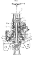
- FIG. 1 is an enlarged sectional view that shows the configuration of a reduction gear mechanism portion of an electric power steering system according to the embodiment of the invention.
- FIG. 2 is a sectional view that shows the overall configuration of the electric power steering system.
- the electric power steering system includes a motor 1 for assisting steering, a reduction gear mechanism A and a steering device 5.
- the reduction gear mechanism A has a worm shaft 3 and a worm wheel 4.
- the worm shaft 3 is coupled to an output shaft 1a of the motor 1 via a shaft coupling 2.
- the worm wheel 4 is in mesh with the worm shaft 3.
- the steering device 5 is coupled to the reduction gear mechanism A.
- the steering device 5 includes a first steering shaft 51, a torsion bar 52 and a second steering shaft 53.
- the first steering shaft 51 is connected at one end to a steering wheel B for steering, and the first steering shaft 51 has a cylindrical portion 51a at other end.
- the torsion bar 52 is inserted in the cylindrical portion 51a of the first steering shaft 51, and is coupled at one end to the cylindrical portion 51a of the first steering shaft 51.
- An outer peripheral portion of one end of the second steering shaft 53 is fitted to an inner peripheral portion of one end of the cylindrical portion 51a, and the other end of the second steering shaft 53 is coupled to the other end of the torsion bar 52.
- the torsion bar 52 is twisted by the action of steering torque applied to the steering wheel B.
- the second steering shaft 53 is connected to, for example, a rack-and-pinion steering mechanism (not shown) via a universal joint.
- the worm shaft 3 of the reduction gear mechanism A has shaft portions 3a and 3b at respective ends.
- the shaft portion 3a at one end is coupled to the output shaft 1a of the motor 1 in a state where the shaft portion 3a is rotatably supported by an aluminum support member 7 via a first rolling bearing 6.
- the shaft portion 3b at the other end is supported by the support member 7 via a second rolling bearing 8.
- An inner ring 6a of the rolling bearing 6 is fitted to the shaft portion 3a via a movement inhibitor 11.
- An inner ring 8a of the rolling bearing 8 is fitted to the shaft portion 3b.
- the worm wheel 4 has an annular tooth element 41 and a core member 42.
- the annular tooth element 41 is made of synthetic resin.
- the core member 42 is made of metal and is connected to the inner side of the annular tooth element 41.
- the core member 42 is fixedly fitted to an intermediate portion of the second steering shaft 53.
- the support member 7 has a first accommodating portion 7a and a second accommodating portion 7b.
- the first accommodating portion 7a accommodates the worm shaft 3, and rotatably supports the shaft portions 3a and 3b of the worm shaft 3 via the rolling bearings 6 and 8.
- the second accommodating portion 7b accommodates the worm wheel 4, and supports the worm wheel 4 via the second steering shaft 53 and two rolling bearings 9 and 10 that are fitted around the second steering shaft 53.
- the first accommodating portion 7a extends in the axial longitudinal direction of the worm shaft 3.
- the first accommodating portion 7a has a support hole 71, an annular groove 72 and a motor mounting portion 73 at one end in the longitudinal direction thereof.
- the rolling bearing 6 is loosely fitted in the support hole 71 so that the rolling bearing 6 is supported.
- the annular groove 72 is contiguous with the support hole 71.
- a snap ring 14 is fitted in the annular groove 72. The snap ring 14 contacts an outer ring 6b of the rolling bearing 6 to restrict movement of the rolling bearing 6 in the axial longitudinal direction.
- the rolling bearing 6 that supports the shaft portion 3a at one end includes the inner ring 6a, the outer ring 6b and a plurality of rolling elements 6c interposed between the inner ring 6a and the outer ring 6b.
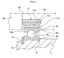
- FIG. 3 is an enlarged sectional view that is taken along the line I-I in FIG. 1 .
- FIG 4 is a perspective view that shows the configuration of a curved leaf spring.
- a support hole 74 is formed at the other end of the first accommodating portion 7a. The support hole 74 is used to support the second rolling bearing 8 and a curved leaf spring 12 fitted around the rolling bearing 8.
- the shaft portion 3b (rolling bearing 8) is pressed against a first inner peripheral surface 74a, the distance H between the rotation centers of the worm shaft 3 and worm wheel 4 (see FIG. 1 ) becomes long.
- the shaft portion 3b (rolling bearing 8) is pressed against a second inner peripheral surface 74b, the distance H becomes short.
- the support hole 74 is formed in such an oval shape that the radius between the first inner peripheral surface 74a and the center of the support hole 74 is longer than the radius between the second inner peripheral surface 74b and the center of the support hole 74.
- the curved leaf spring 12 may be deflected between the first inner peripheral surface 74a and the rolling bearing 8.
- a recess 74c is formed in the middle of the first inner peripheral surface 74a in the circumferential direction. The recess 74c accommodates ends 12a and 12b of the curved leaf spring 12.
- the curved leaf spring 12 is formed of a band-like spring steel of which the intermediate portion in the longitudinal direction is curved in a substantially circular shape along the outer peripheral surface of the rolling bearing 8 and that has a length larger than the perimeter of the rolling bearing 8.
- the one end 12a has a cutout 12c at its center in the widthwise direction.
- the other end 12b has cutouts 12d at respective sides in the widthwise direction.
- the ends 12a are inserted into the cutout recesses 12d or the end 12b is inserted into the cutout recess 12c to thereby allow the ends 12a and 12b to intersect with each other without any increase in width.
- the ends 12a and 12b are located away from the outer peripheral surface of the rolling bearing 8, that is, a curved portion 12e.
- the ends 12a and 12b of the curved leaf spring 12 are inserted into the recess 74c and are deflected within the recess 74c to thereby urge, via the rolling bearing 8, the worm shaft 3 in the direction in which the distance H between the rotation centers is reduced.
- a plurality of spring pieces 12f is formed integrally with the curved leaf spring 12.
- the spring pieces 12f are formed at one side of the curved portion 12e of the curved leaf spring 12 in the widthwise direction at positions apart from each other in the longitudinal direction of the curved leaf spring 12.
- the spring pieces 12f contact a side surface 74d of the support hole 74 to press the second rolling bearing 8 toward the motor 1.
- the spring pieces 12f each protrude so as to be inclined inward with respect to the peripheral surface of the curved portion 12e.
- Each of the spring pieces 12f is deflected by contacting the side surface 74d of the support hole 74.
- the reaction force of the elastic restoring force of each spring piece 12f acts on the outer ring 8b of the second rolling bearing 8 and presses the worm shaft 3 toward the motor 1 via the outer ring 8b, the rolling elements and the inner ring 8a.
- a torque sensor 13 is installed in the support member 7.
- the torque sensor 13 detects a steering torque applied to the steering wheel B on the basis of a relative rotational displacement between the steering shafts 51 and 53 in response to the twist of the torsion bar 52.
- the motor 1 is subjected to drive control on the basis of the torque detected by the torque sensor 13, and the like.
- the curved leaf spring 12 is inserted into the support hole 74 of the support member 7 and then the ends 12a and 12b of the curved leaf spring 12 are inserted into the recess 74c to set the position of the curved leaf spring 12.
- the inner ring 6a of the rolling bearing 6 is fitted to the shaft portion 3a of the worm shaft 3 via the movement inhibitor 11, and the inner ring 8a of the rolling bearing 8 is fitted to the shaft portion 3b of the worm shaft 3.
- the worm shaft 3 is inserted in the first accommodating portion 7a.
- the second rolling bearing 8 is placed on the inner side of the curved leaf spring 12.
- the first rolling bearing 6 is loosely fitted in the support hole 71.
- the snap ring 14 is fitted in the annular groove 72.
- the ends 12a and 12b of the curved leaf spring 12 that urges the installed worm shaft 3 are inserted in the recess 74c of the support member 7 to urge the rolling bearing 8 and the worm shaft 3 supported by the rolling bearing 8 in the direction in which the distance H between the rotation centers is reduced (toward the worm wheel) using the deflection of the ends 12a and 12b.
- the curved leaf spring 12 is curved along the outer peripheral surface of the rolling bearing 8, so it is possible to eliminate the gap between the curved leaf spring 12 and the rolling bearing 8 and the gap between the curved leaf spring 12 and the second inner peripheral surface 74b of the support hole 74. Thus, it is possible to restrict the worm shaft 3 from moving in a direction that intersects with the direction in which the distance H between the rotation centers increases or reduces. More specific description will be provided below.
- the tooth traces of the worm shaft 3 and worm wheel 4 are twisted with respect to the rotation center line.
- the worm shaft 3 urged by the curved leaf spring 12 as described above oscillates, in the direction in which the distance H between the rotation centers increases or reduces, about the support portion of the worm shaft 3, supported by the first rolling bearing 6.
- the first rolling bearing 6 supports the shaft portion 3a of the worm shaft 3 via the movement inhibitor 14, so there is no gap between the worm shaft 3 and the bearing 6.
- the worm shaft 3 is coupled to the output shaft 1a via the shaft coupling 2 having an elastic tooth element 23, so an allowable oscillation amount of the worm shaft 3 may be increased.
- the worm shaft 3 is pressed in a direction away from the motor 1 by the shaft coupling 2 having first and second coupling elements 21 and 22 and the elastic tooth element 23 interposed between the coupling elements 21 and 22.
- the worm shaft 3 is pressed toward the motor 1 by the spring pieces 12f of the curved leaf spring 12, so it is possible to maintain a balance between forces that act on the worm shaft 3 in the axial longitudinal direction to thereby make it possible to improve the rotational performance of the worm shaft 3.
- the worm shaft 3 is connected to the output shaft 1a by the shaft coupling 2 having the elastic tooth element 23, so propagation of noise generated at the motor 1-side to the worm shaft 3 is interrupted by the elastic tooth element 23, and noise at the shaft coupling portion is eliminated.
- the movement inhibitor 11 As shown in FIG 1 and FIG 5 , the movement inhibitor 11 according to the present embodiment is fitted to and held by the shaft portion 3a of the worm shaft 3 supported rotatably by the rolling bearing 6.
- the movement inhibitor 11 inhibits movement of the worm shaft 3 in the axial longitudinal direction.
- the movement inhibitor 11 includes a metal inner ring 11 a, a metal outer ring 11c and an elastic element 11b.
- the metal inner ring 11 a is fitted around the outer peripheral surface of the shaft portion 3 a of the worm shaft 3.
- the inner peripheral surface of the metal outer ring 11c is larger in diameter than the outer peripheral surface of the metal inner ring 11a.
- the metal outer ring 11c is fitted to the inner ring 6a of the rolling bearing 6.
- the elastic element 11b is bonded by cure adhesion, or the like, between the outer peripheral surface of the inner ring 11 a and the inner peripheral surface of the outer ring 11c.
- the position of the inner ring 11a is determined by an end surface 3c of the worm shaft 3 and a coupling end surface 22a.
- the outer ring 11c has the same size in the axial direction of the worm shaft 3 as the inner ring 6a.
- the elastic element 11b has a substantially trapezoidal shape in cross section so as to connect the ends of both rings 11a and 11c.
- the inner ring 11a is press-fitted to the shaft portion 3a.
- a coupling 22 is fitted to the shaft portion 3a.
- An elastic tooth element 23 is fitted between the coupling 22 and a first coupling element 21.
- the coupling 22 is fitted to the first coupling element 21 via the elastic tooth element 23.
- a shaft coupling 2 includes the coupling 22, the first coupling element 21 and the elastic tooth element 23.
- the shaft coupling 2 is coupled to the output shaft 1a (see FIG 1 ).
- the outer ring 11c has a radial protruding portion 11d at the center on the inner peripheral surface.
- the radial protruding portion 11d protrudes toward the elastic element 11b.
- the protruding portion 11d may be formed not at the outer ring 11c but at the inner ring 11a.
- the elastic element 11b has cylindrical portion, and a recess that is formed in a peripheral surface of the cylindrical portion and that receives the protruding portion 11d. Note that, instead of the protruding portion of the outer ring 11c or the inner ring 11a, a recess (not shown in the figure) may be formed in the outer ring 11c or the inner ring 11a.
- a protruding portion may be formed at the elastic element 11b.
- the shaft portion 3a is allowed to move in the radial direction within a predetermined range that corresponds to the distance between the outer peripheral surface of the protruding portion 11d and the inner peripheral surface of the inner ring 11 a.
- the outer peripheral surface of the protruding portion 11d substantially contacts the inner peripheral surface of the inner ring 11 a, the movement of the worm shaft 3 in the radial direction is restricted and thus the worm shaft 3 is prevented from moving by an excessive amount. As a result, durability of the elastic member 11b is secured.
- the curved leaf spring 12 presses the worm shaft 3 toward the worm wheel 4.
- the worm shaft 3 oscillates about the shaft portion 3a supported by the bearing 6.
- the shaft portion 3a is elastically supported by the bearing 6 owing to the movement inhibitor 11, so highly accurate gap size management between the outer peripheral surface of the shaft portion and the inner peripheral surface of the bearing is not required unlike in the existing art.
- the worm shaft 3 is supported movably in the axial direction by the movement inhibitor 11.
- the movement inhibitor 11 restricts the amount of movement of the shaft portion 3a in the axial direction and in the radial direction with respect to the bearing 6, so load on the elastic element 11b is suppressed to thereby improve the durability of the elastic element 11b.
- the movement inhibitor 11 restricts movement of the outer ring 11c in the axial direction and in the radial direction, so load on the elastic element 11b is restricted to impart durability to the elastic element 11b.
- the elastic element when the tooth surface of the worm shaft contacts the tooth surface of the worm wheel, the elastic element is deformed to move the rotary shaft in at least one of the axial direction and the radial direction with respect to the housing. According to the present embodiment, it is possible to cope with a large backlash, and the elastic element damps a collision between the tooth surfaces against vibrations transmitted form wheels and against vibrations transmitted from the motor to thereby make it possible to reduce a rattle of the tooth surfaces.
- An electric power steering system includes a worm reduction gear. An end portion of worm shaft, the end portion being distant from a motor, is urged toward a worm wheel. The worm shaft is supported by a bearing at an end portion close to the motor. A movement inhibitor that includes an elastic element is arranged between the worm shaft and the bearing. The movement inhibitor allows the worm shaft to move within a predetermined range in a radial direction of the worm shaft with respect to the bearing and allows the worm shaft to move within a predetermined range in an axial direction of the worm shaft with respect to the bearing.
Landscapes
- Engineering & Computer Science (AREA)
- General Engineering & Computer Science (AREA)
- Mechanical Engineering (AREA)
- Chemical & Material Sciences (AREA)
- Combustion & Propulsion (AREA)
- Transportation (AREA)
- Power Steering Mechanism (AREA)
- Gear Transmission (AREA)
Applications Claiming Priority (3)
| Application Number | Priority Date | Filing Date | Title |
|---|---|---|---|
| JP2010192555 | 2010-08-30 | ||
| JP2011057906A JP2012071815A (ja) | 2010-08-30 | 2011-03-16 | 電動パワーステアリング装置 |
| JP2011137303A JP2012071820A (ja) | 2010-08-30 | 2011-06-21 | 電動パワーステアリング装置 |
Publications (3)
| Publication Number | Publication Date |
|---|---|
| EP2423075A2 true EP2423075A2 (de) | 2012-02-29 |
| EP2423075A3 EP2423075A3 (de) | 2013-12-04 |
| EP2423075B1 EP2423075B1 (de) | 2014-11-26 |
Family
ID=44534054
Family Applications (1)
| Application Number | Title | Priority Date | Filing Date |
|---|---|---|---|
| EP11179134.9A Not-in-force EP2423075B1 (de) | 2010-08-30 | 2011-08-29 | Elektrisches Servolenksystem |
Country Status (3)
| Country | Link |
|---|---|
| US (1) | US8381868B2 (de) |
| EP (1) | EP2423075B1 (de) |
| CN (1) | CN102398627B (de) |
Cited By (3)
| Publication number | Priority date | Publication date | Assignee | Title |
|---|---|---|---|---|
| DE102013020599A1 (de) | 2013-12-13 | 2015-06-18 | Thyssenkrupp Presta Ag | Verfahren zum Einlaufen eines Schneckenradgetriebes |
| DE102014105921A1 (de) | 2014-04-28 | 2015-10-29 | Thyssenkrupp Presta Ag | Vorrichtung zum Aufbringen einer Hilfskraft in einer Kraftfahrzeuglenkung |
| DE102014110306A1 (de) | 2014-07-22 | 2016-01-28 | Thyssenkrupp Ag | Elektromechanische Servolenkung |
Families Citing this family (12)
| Publication number | Priority date | Publication date | Assignee | Title |
|---|---|---|---|---|
| JP5566750B2 (ja) * | 2010-03-31 | 2014-08-06 | 本田技研工業株式会社 | 鞍乗り型車両の電動パワーステアリング装置 |
| DE102012103147A1 (de) * | 2012-04-12 | 2013-10-17 | Zf Lenksysteme Gmbh | Loslager für ein lenkgetriebe |
| EP2842835A4 (de) * | 2012-04-25 | 2016-04-06 | Jtekt Corp | Elektrische servolenkvorrichtung |
| JP6020893B2 (ja) * | 2012-07-27 | 2016-11-02 | 株式会社ジェイテクト | 電動パワーステアリング装置 |
| JP5908380B2 (ja) * | 2012-09-24 | 2016-04-26 | 日立オートモティブシステムズステアリング株式会社 | パワーステアリング装置およびパワーステアリング装置用減速機 |
| JP5934733B2 (ja) * | 2014-03-06 | 2016-06-15 | 富士重工業株式会社 | ステアリング装置 |
| DE102016211706B3 (de) * | 2016-06-29 | 2017-12-14 | Ford Global Technologies, Llc | Getriebeeinheit für ein Kraftfahrzeug |
| EP3820762B1 (de) * | 2018-07-11 | 2022-11-16 | thyssenkrupp Presta AG | Verstellantrieb für eine lenksäule, motorisch verstellbare lenksäule für ein kraftfahrzeug, und verfahren zur einstellung einer lageranordnung eines verstellantriebs |
| DE102020200285A1 (de) * | 2020-01-11 | 2021-07-15 | Robert Bosch Gesellschaft mit beschränkter Haftung | Schneckengetriebe |
| JP2023510097A (ja) * | 2020-01-16 | 2023-03-13 | サン-ゴバン パフォーマンス プラスティックス レンコール リミティド | ステアリング組立体用の軸受 |
| CN114635916A (zh) * | 2022-03-29 | 2022-06-17 | 奇瑞汽车股份有限公司 | 轴承固定结构、轴承组件及减速机 |
| CN118220310A (zh) * | 2023-09-28 | 2024-06-21 | 比亚迪股份有限公司 | 传动装置、转向机构和车辆 |
Citations (1)
| Publication number | Priority date | Publication date | Assignee | Title |
|---|---|---|---|---|
| US7213677B2 (en) | 2002-12-24 | 2007-05-08 | Koyo Seiko Co., Ltd. | Motor-driven type power steering apparatus |
Family Cites Families (7)
| Publication number | Priority date | Publication date | Assignee | Title |
|---|---|---|---|---|
| JPH04349334A (ja) | 1991-05-24 | 1992-12-03 | Shimadzu Corp | 飛行時間型イオン散乱分析装置 |
| JP3915610B2 (ja) | 1997-05-29 | 2007-05-16 | 日本精工株式会社 | 電動式パワーステアリング装置 |
| US7077235B2 (en) * | 2001-12-03 | 2006-07-18 | Nsk Ltd. | Electric power steering device |
| JP4442421B2 (ja) * | 2002-12-09 | 2010-03-31 | 日本精工株式会社 | 電動パワーステアリング装置 |
| CN100577490C (zh) * | 2004-04-06 | 2010-01-06 | 日本精工株式会社 | 电动转向装置 |
| JP5017927B2 (ja) * | 2006-05-31 | 2012-09-05 | 日本精工株式会社 | 電動パワーステアリング装置 |
| JP2008254495A (ja) * | 2007-04-02 | 2008-10-23 | Jtekt Corp | 電動パワーステアリング装置 |
-
2011
- 2011-08-23 US US13/215,882 patent/US8381868B2/en not_active Expired - Fee Related
- 2011-08-26 CN CN201110253501.7A patent/CN102398627B/zh not_active Expired - Fee Related
- 2011-08-29 EP EP11179134.9A patent/EP2423075B1/de not_active Not-in-force
Patent Citations (1)
| Publication number | Priority date | Publication date | Assignee | Title |
|---|---|---|---|---|
| US7213677B2 (en) | 2002-12-24 | 2007-05-08 | Koyo Seiko Co., Ltd. | Motor-driven type power steering apparatus |
Cited By (9)
| Publication number | Priority date | Publication date | Assignee | Title |
|---|---|---|---|---|
| DE102013020599A1 (de) | 2013-12-13 | 2015-06-18 | Thyssenkrupp Presta Ag | Verfahren zum Einlaufen eines Schneckenradgetriebes |
| WO2015086156A1 (de) | 2013-12-13 | 2015-06-18 | Thyssenkrupp Presta Ag | Verfahren zum einlaufen eines schneckenradgetriebes |
| US10260620B2 (en) | 2013-12-13 | 2019-04-16 | Thyssenkrupp Presta Ag | Method for the running in of a worm-wheel gear |
| DE102013020599B4 (de) | 2013-12-13 | 2020-06-10 | Thyssenkrupp Presta Ag | Verfahren zum Einlaufen eines Schneckenradgetriebes |
| DE102014105921A1 (de) | 2014-04-28 | 2015-10-29 | Thyssenkrupp Presta Ag | Vorrichtung zum Aufbringen einer Hilfskraft in einer Kraftfahrzeuglenkung |
| WO2015165698A1 (de) | 2014-04-28 | 2015-11-05 | Thyssenkrupp Presta Ag | Vorrichtung zum aufbringen einer hilfskraft in einer kraftfahrzeuglenkung |
| US10000231B2 (en) | 2014-04-28 | 2018-06-19 | Thyssenkrupp Presta Ag | Device for applying an auxiliary force in a motor vehicle steering system |
| DE102014110306A1 (de) | 2014-07-22 | 2016-01-28 | Thyssenkrupp Ag | Elektromechanische Servolenkung |
| US10252742B2 (en) | 2014-07-22 | 2019-04-09 | Thyssenkrupp Presta Ag | Electromechanical power steering system |
Also Published As
| Publication number | Publication date |
|---|---|
| CN102398627B (zh) | 2015-12-09 |
| US8381868B2 (en) | 2013-02-26 |
| US20120048640A1 (en) | 2012-03-01 |
| EP2423075A3 (de) | 2013-12-04 |
| EP2423075B1 (de) | 2014-11-26 |
| CN102398627A (zh) | 2012-04-04 |
Similar Documents
| Publication | Publication Date | Title |
|---|---|---|
| EP2423075B1 (de) | Elektrisches Servolenksystem | |
| JP3951913B2 (ja) | 電動式パワーステアリング装置 | |
| JP5645070B2 (ja) | 電動パワーステアリング装置 | |
| JP4868215B2 (ja) | 電動パワーステアリング装置 | |
| CN108372880B (zh) | 电动助力转向设备的减速器 | |
| EP2371675B1 (de) | Elektrische Servolenkung | |
| JP4563424B2 (ja) | 電動式操向装置 | |
| JP6020893B2 (ja) | 電動パワーステアリング装置 | |
| US7077235B2 (en) | Electric power steering device | |
| US9499194B2 (en) | Electric power steering system | |
| JP2006175891A (ja) | 電動パワーステアリング装置 | |
| JP4385286B2 (ja) | 電動パワーステアリング装置 | |
| JP4501068B2 (ja) | 電動パワーステアリング装置 | |
| KR20170076256A (ko) | 전동식 동력 보조 조향장치의 감속기 | |
| KR20180089629A (ko) | 전동식 동력 보조 조향장치의 감속기 | |
| JP2008105649A (ja) | 電動パワーステアリング装置 | |
| KR20110096816A (ko) | 전동식 동력 보조 조향장치의 감속기 및 이를 구비한 전동식 동력 보조 조향장치 | |
| EP2966317A1 (de) | Schneckenuntersetzungsgetriebe und elektrisches servolenksystem damit | |
| JP2006117049A (ja) | 電動パワーステアリング装置 | |
| JP2012087881A (ja) | 動力伝達継手および電動パワーステアリング装置 | |
| JP2004249844A (ja) | 電動パワーステアリング装置 | |
| JP4085867B2 (ja) | ウォーム支持装置及び電動パワーステアリング装置 | |
| EP1867552A1 (de) | Zahnstangenlenkungsrad | |
| JP2012071815A (ja) | 電動パワーステアリング装置 | |
| KR20220123833A (ko) | 자동차 조향장치의 감속기 |
Legal Events
| Date | Code | Title | Description |
|---|---|---|---|
| AK | Designated contracting states |
Kind code of ref document: A2 Designated state(s): AL AT BE BG CH CY CZ DE DK EE ES FI FR GB GR HR HU IE IS IT LI LT LU LV MC MK MT NL NO PL PT RO RS SE SI SK SM TR |
|
| AX | Request for extension of the european patent |
Extension state: BA ME |
|
| PUAI | Public reference made under article 153(3) epc to a published international application that has entered the european phase |
Free format text: ORIGINAL CODE: 0009012 |
|
| PUAL | Search report despatched |
Free format text: ORIGINAL CODE: 0009013 |
|
| AK | Designated contracting states |
Kind code of ref document: A3 Designated state(s): AL AT BE BG CH CY CZ DE DK EE ES FI FR GB GR HR HU IE IS IT LI LT LU LV MC MK MT NL NO PL PT RO RS SE SI SK SM TR |
|
| AX | Request for extension of the european patent |
Extension state: BA ME |
|
| RIC1 | Information provided on ipc code assigned before grant |
Ipc: F16C 27/04 20060101ALI20131025BHEP Ipc: B62D 5/04 20060101AFI20131025BHEP Ipc: F16H 57/021 20120101ALN20131025BHEP |
|
| 17P | Request for examination filed |
Effective date: 20140429 |
|
| GRAP | Despatch of communication of intention to grant a patent |
Free format text: ORIGINAL CODE: EPIDOSNIGR1 |
|
| RIC1 | Information provided on ipc code assigned before grant |
Ipc: F16H 57/021 20120101ALN20140626BHEP Ipc: B62D 5/04 20060101AFI20140626BHEP Ipc: F16C 27/04 20060101ALI20140626BHEP |
|
| INTG | Intention to grant announced |
Effective date: 20140708 |
|
| RIN1 | Information on inventor provided before grant (corrected) |
Inventor name: HAMAKITA, JUN |
|
| GRAS | Grant fee paid |
Free format text: ORIGINAL CODE: EPIDOSNIGR3 |
|
| GRAA | (expected) grant |
Free format text: ORIGINAL CODE: 0009210 |
|
| AK | Designated contracting states |
Kind code of ref document: B1 Designated state(s): AL AT BE BG CH CY CZ DE DK EE ES FI FR GB GR HR HU IE IS IT LI LT LU LV MC MK MT NL NO PL PT RO RS SE SI SK SM TR |
|
| REG | Reference to a national code |
Ref country code: GB Ref legal event code: FG4D |
|
| REG | Reference to a national code |
Ref country code: CH Ref legal event code: EP |
|
| REG | Reference to a national code |
Ref country code: AT Ref legal event code: REF Ref document number: 697990 Country of ref document: AT Kind code of ref document: T Effective date: 20141215 |
|
| REG | Reference to a national code |
Ref country code: IE Ref legal event code: FG4D |
|
| REG | Reference to a national code |
Ref country code: DE Ref legal event code: R096 Ref document number: 602011011683 Country of ref document: DE Effective date: 20150108 |
|
| REG | Reference to a national code |
Ref country code: NL Ref legal event code: VDEP Effective date: 20141126 |
|
| REG | Reference to a national code |
Ref country code: AT Ref legal event code: MK05 Ref document number: 697990 Country of ref document: AT Kind code of ref document: T Effective date: 20141126 |
|
| REG | Reference to a national code |
Ref country code: LT Ref legal event code: MG4D |
|
| PG25 | Lapsed in a contracting state [announced via postgrant information from national office to epo] |
Ref country code: FI Free format text: LAPSE BECAUSE OF FAILURE TO SUBMIT A TRANSLATION OF THE DESCRIPTION OR TO PAY THE FEE WITHIN THE PRESCRIBED TIME-LIMIT Effective date: 20141126 Ref country code: NO Free format text: LAPSE BECAUSE OF FAILURE TO SUBMIT A TRANSLATION OF THE DESCRIPTION OR TO PAY THE FEE WITHIN THE PRESCRIBED TIME-LIMIT Effective date: 20150226 Ref country code: IS Free format text: LAPSE BECAUSE OF FAILURE TO SUBMIT A TRANSLATION OF THE DESCRIPTION OR TO PAY THE FEE WITHIN THE PRESCRIBED TIME-LIMIT Effective date: 20150326 Ref country code: LT Free format text: LAPSE BECAUSE OF FAILURE TO SUBMIT A TRANSLATION OF THE DESCRIPTION OR TO PAY THE FEE WITHIN THE PRESCRIBED TIME-LIMIT Effective date: 20141126 Ref country code: ES Free format text: LAPSE BECAUSE OF FAILURE TO SUBMIT A TRANSLATION OF THE DESCRIPTION OR TO PAY THE FEE WITHIN THE PRESCRIBED TIME-LIMIT Effective date: 20141126 Ref country code: NL Free format text: LAPSE BECAUSE OF FAILURE TO SUBMIT A TRANSLATION OF THE DESCRIPTION OR TO PAY THE FEE WITHIN THE PRESCRIBED TIME-LIMIT Effective date: 20141126 Ref country code: PT Free format text: LAPSE BECAUSE OF FAILURE TO SUBMIT A TRANSLATION OF THE DESCRIPTION OR TO PAY THE FEE WITHIN THE PRESCRIBED TIME-LIMIT Effective date: 20150326 |
|
| PG25 | Lapsed in a contracting state [announced via postgrant information from national office to epo] |
Ref country code: LV Free format text: LAPSE BECAUSE OF FAILURE TO SUBMIT A TRANSLATION OF THE DESCRIPTION OR TO PAY THE FEE WITHIN THE PRESCRIBED TIME-LIMIT Effective date: 20141126 Ref country code: RS Free format text: LAPSE BECAUSE OF FAILURE TO SUBMIT A TRANSLATION OF THE DESCRIPTION OR TO PAY THE FEE WITHIN THE PRESCRIBED TIME-LIMIT Effective date: 20141126 Ref country code: CY Free format text: LAPSE BECAUSE OF FAILURE TO SUBMIT A TRANSLATION OF THE DESCRIPTION OR TO PAY THE FEE WITHIN THE PRESCRIBED TIME-LIMIT Effective date: 20141126 Ref country code: SE Free format text: LAPSE BECAUSE OF FAILURE TO SUBMIT A TRANSLATION OF THE DESCRIPTION OR TO PAY THE FEE WITHIN THE PRESCRIBED TIME-LIMIT Effective date: 20141126 Ref country code: HR Free format text: LAPSE BECAUSE OF FAILURE TO SUBMIT A TRANSLATION OF THE DESCRIPTION OR TO PAY THE FEE WITHIN THE PRESCRIBED TIME-LIMIT Effective date: 20141126 Ref country code: AT Free format text: LAPSE BECAUSE OF FAILURE TO SUBMIT A TRANSLATION OF THE DESCRIPTION OR TO PAY THE FEE WITHIN THE PRESCRIBED TIME-LIMIT Effective date: 20141126 Ref country code: GR Free format text: LAPSE BECAUSE OF FAILURE TO SUBMIT A TRANSLATION OF THE DESCRIPTION OR TO PAY THE FEE WITHIN THE PRESCRIBED TIME-LIMIT Effective date: 20150227 |
|
| PG25 | Lapsed in a contracting state [announced via postgrant information from national office to epo] |
Ref country code: RO Free format text: LAPSE BECAUSE OF FAILURE TO SUBMIT A TRANSLATION OF THE DESCRIPTION OR TO PAY THE FEE WITHIN THE PRESCRIBED TIME-LIMIT Effective date: 20141126 Ref country code: CZ Free format text: LAPSE BECAUSE OF FAILURE TO SUBMIT A TRANSLATION OF THE DESCRIPTION OR TO PAY THE FEE WITHIN THE PRESCRIBED TIME-LIMIT Effective date: 20141126 Ref country code: DK Free format text: LAPSE BECAUSE OF FAILURE TO SUBMIT A TRANSLATION OF THE DESCRIPTION OR TO PAY THE FEE WITHIN THE PRESCRIBED TIME-LIMIT Effective date: 20141126 Ref country code: SK Free format text: LAPSE BECAUSE OF FAILURE TO SUBMIT A TRANSLATION OF THE DESCRIPTION OR TO PAY THE FEE WITHIN THE PRESCRIBED TIME-LIMIT Effective date: 20141126 Ref country code: EE Free format text: LAPSE BECAUSE OF FAILURE TO SUBMIT A TRANSLATION OF THE DESCRIPTION OR TO PAY THE FEE WITHIN THE PRESCRIBED TIME-LIMIT Effective date: 20141126 |
|
| REG | Reference to a national code |
Ref country code: DE Ref legal event code: R097 Ref document number: 602011011683 Country of ref document: DE |
|
| PG25 | Lapsed in a contracting state [announced via postgrant information from national office to epo] |
Ref country code: PL Free format text: LAPSE BECAUSE OF FAILURE TO SUBMIT A TRANSLATION OF THE DESCRIPTION OR TO PAY THE FEE WITHIN THE PRESCRIBED TIME-LIMIT Effective date: 20141126 |
|
| PLBE | No opposition filed within time limit |
Free format text: ORIGINAL CODE: 0009261 |
|
| STAA | Information on the status of an ep patent application or granted ep patent |
Free format text: STATUS: NO OPPOSITION FILED WITHIN TIME LIMIT |
|
| 26N | No opposition filed |
Effective date: 20150827 |
|
| PG25 | Lapsed in a contracting state [announced via postgrant information from national office to epo] |
Ref country code: IT Free format text: LAPSE BECAUSE OF FAILURE TO SUBMIT A TRANSLATION OF THE DESCRIPTION OR TO PAY THE FEE WITHIN THE PRESCRIBED TIME-LIMIT Effective date: 20141126 |
|
| PG25 | Lapsed in a contracting state [announced via postgrant information from national office to epo] |
Ref country code: SI Free format text: LAPSE BECAUSE OF FAILURE TO SUBMIT A TRANSLATION OF THE DESCRIPTION OR TO PAY THE FEE WITHIN THE PRESCRIBED TIME-LIMIT Effective date: 20141126 |
|
| PG25 | Lapsed in a contracting state [announced via postgrant information from national office to epo] |
Ref country code: LU Free format text: LAPSE BECAUSE OF FAILURE TO SUBMIT A TRANSLATION OF THE DESCRIPTION OR TO PAY THE FEE WITHIN THE PRESCRIBED TIME-LIMIT Effective date: 20150829 Ref country code: MC Free format text: LAPSE BECAUSE OF FAILURE TO SUBMIT A TRANSLATION OF THE DESCRIPTION OR TO PAY THE FEE WITHIN THE PRESCRIBED TIME-LIMIT Effective date: 20141126 |
|
| REG | Reference to a national code |
Ref country code: CH Ref legal event code: PL |
|
| GBPC | Gb: european patent ceased through non-payment of renewal fee |
Effective date: 20150829 |
|
| PG25 | Lapsed in a contracting state [announced via postgrant information from national office to epo] |
Ref country code: LI Free format text: LAPSE BECAUSE OF NON-PAYMENT OF DUE FEES Effective date: 20150831 Ref country code: CH Free format text: LAPSE BECAUSE OF NON-PAYMENT OF DUE FEES Effective date: 20150831 |
|
| REG | Reference to a national code |
Ref country code: IE Ref legal event code: MM4A |
|
| REG | Reference to a national code |
Ref country code: FR Ref legal event code: PLFP Year of fee payment: 6 |
|
| PG25 | Lapsed in a contracting state [announced via postgrant information from national office to epo] |
Ref country code: GB Free format text: LAPSE BECAUSE OF NON-PAYMENT OF DUE FEES Effective date: 20150829 Ref country code: IE Free format text: LAPSE BECAUSE OF NON-PAYMENT OF DUE FEES Effective date: 20150829 |
|
| PG25 | Lapsed in a contracting state [announced via postgrant information from national office to epo] |
Ref country code: MT Free format text: LAPSE BECAUSE OF FAILURE TO SUBMIT A TRANSLATION OF THE DESCRIPTION OR TO PAY THE FEE WITHIN THE PRESCRIBED TIME-LIMIT Effective date: 20141126 |
|
| PG25 | Lapsed in a contracting state [announced via postgrant information from national office to epo] |
Ref country code: SM Free format text: LAPSE BECAUSE OF FAILURE TO SUBMIT A TRANSLATION OF THE DESCRIPTION OR TO PAY THE FEE WITHIN THE PRESCRIBED TIME-LIMIT Effective date: 20141126 Ref country code: BG Free format text: LAPSE BECAUSE OF FAILURE TO SUBMIT A TRANSLATION OF THE DESCRIPTION OR TO PAY THE FEE WITHIN THE PRESCRIBED TIME-LIMIT Effective date: 20141126 Ref country code: HU Free format text: LAPSE BECAUSE OF FAILURE TO SUBMIT A TRANSLATION OF THE DESCRIPTION OR TO PAY THE FEE WITHIN THE PRESCRIBED TIME-LIMIT; INVALID AB INITIO Effective date: 20110829 |
|
| REG | Reference to a national code |
Ref country code: FR Ref legal event code: PLFP Year of fee payment: 7 |
|
| PG25 | Lapsed in a contracting state [announced via postgrant information from national office to epo] |
Ref country code: TR Free format text: LAPSE BECAUSE OF FAILURE TO SUBMIT A TRANSLATION OF THE DESCRIPTION OR TO PAY THE FEE WITHIN THE PRESCRIBED TIME-LIMIT Effective date: 20141126 |
|
| PG25 | Lapsed in a contracting state [announced via postgrant information from national office to epo] |
Ref country code: BE Free format text: LAPSE BECAUSE OF FAILURE TO SUBMIT A TRANSLATION OF THE DESCRIPTION OR TO PAY THE FEE WITHIN THE PRESCRIBED TIME-LIMIT Effective date: 20141126 |
|
| PG25 | Lapsed in a contracting state [announced via postgrant information from national office to epo] |
Ref country code: MK Free format text: LAPSE BECAUSE OF FAILURE TO SUBMIT A TRANSLATION OF THE DESCRIPTION OR TO PAY THE FEE WITHIN THE PRESCRIBED TIME-LIMIT Effective date: 20141126 |
|
| REG | Reference to a national code |
Ref country code: FR Ref legal event code: PLFP Year of fee payment: 8 |
|
| PG25 | Lapsed in a contracting state [announced via postgrant information from national office to epo] |
Ref country code: AL Free format text: LAPSE BECAUSE OF FAILURE TO SUBMIT A TRANSLATION OF THE DESCRIPTION OR TO PAY THE FEE WITHIN THE PRESCRIBED TIME-LIMIT Effective date: 20141126 |
|
| PGFP | Annual fee paid to national office [announced via postgrant information from national office to epo] |
Ref country code: FR Payment date: 20230703 Year of fee payment: 13 Ref country code: DE Payment date: 20230705 Year of fee payment: 13 |
|
| REG | Reference to a national code |
Ref country code: DE Ref legal event code: R119 Ref document number: 602011011683 Country of ref document: DE |
|
| PG25 | Lapsed in a contracting state [announced via postgrant information from national office to epo] |
Ref country code: DE Free format text: LAPSE BECAUSE OF NON-PAYMENT OF DUE FEES Effective date: 20250301 |
|
| PG25 | Lapsed in a contracting state [announced via postgrant information from national office to epo] |
Ref country code: FR Free format text: LAPSE BECAUSE OF NON-PAYMENT OF DUE FEES Effective date: 20240831 |