EP2423151B2 - Dispositif de capteur angulaire de rotation à équilibrage de jeu radial - Google Patents
Dispositif de capteur angulaire de rotation à équilibrage de jeu radial Download PDFInfo
- Publication number
- EP2423151B2 EP2423151B2 EP11175629.2A EP11175629A EP2423151B2 EP 2423151 B2 EP2423151 B2 EP 2423151B2 EP 11175629 A EP11175629 A EP 11175629A EP 2423151 B2 EP2423151 B2 EP 2423151B2
- Authority
- EP
- European Patent Office
- Prior art keywords
- rotary encoder
- rotation
- axis
- rotational
- unwinding
- Prior art date
- Legal status (The legal status is an assumption and is not a legal conclusion. Google has not performed a legal analysis and makes no representation as to the accuracy of the status listed.)
- Not-in-force
Links
- 230000002093 peripheral effect Effects 0.000 claims description 12
- 239000013013 elastic material Substances 0.000 claims description 3
- 239000004033 plastic Substances 0.000 claims description 2
- 238000005096 rolling process Methods 0.000 description 67
- 238000004519 manufacturing process Methods 0.000 description 3
- 230000001419 dependent effect Effects 0.000 description 1
- 230000005489 elastic deformation Effects 0.000 description 1
- 238000005259 measurement Methods 0.000 description 1
Images

Classifications
-
- B—PERFORMING OPERATIONS; TRANSPORTING
- B66—HOISTING; LIFTING; HAULING
- B66C—CRANES; LOAD-ENGAGING ELEMENTS OR DEVICES FOR CRANES, CAPSTANS, WINCHES, OR TACKLES
- B66C23/00—Cranes comprising essentially a beam, boom, or triangular structure acting as a cantilever and mounted for translatory of swinging movements in vertical or horizontal planes or a combination of such movements, e.g. jib-cranes, derricks, tower cranes
- B66C23/62—Constructional features or details
- B66C23/84—Slewing gear
Definitions
- the invention relates to a radial play compensating Drehwinkelgeberan Aunt for the crane slewing connection, in particular for a rotary connection to working machines, in particular for a ball slewing connection or roller slewing connection between the upper and lower chassis of a mobile crane.
- the turntable of a superstructure is usually rotatably connected to a mobile crane via a ball slewing or roller slewing with the undercarriage. If the rotary joint is not exactly centered on the turntable, a certain radial tolerance between the rotary joint and turntable may occur during the initial assembly of the rotary joint on the turntable. If a rotary encoder is arranged on the turntable of the superstructure, it then comes to the intervention of the rotary encoder on the rotating ring gear of the rotary joint also to an unwanted radial tolerance.
- the bendable arm projecting beyond the turntable can be easily damaged together with the rotary encoder,
- the undercarriage lifting means such as belts or chains that hang on the arm and bend it.
- the present invention is therefore an object of the invention to provide a rotary encoder, which compensates for the radial play occurring at the rotary joint and at the same time avoids damage to the rotary encoder.
- the rotary encoder arrangement according to the invention is provided for a crane turning connection, which allows a rotation between two rotary elements, for example a top and an undercarriage of a mobile crane.
- two rotary elements for example a top and an undercarriage of a mobile crane.
- the rotation angle sensor arrangement comprises an elastic rolling element, which rotates coupled to the rotary encoder via its peripheral surface on the first rotary element, the rotary encoder detects the rotational movement about the axis of rotation of the rolling element and the rolling element is held translationally and / or rotationally adjustable by the second rotary member by means of a bearing, so as to vary the distance of the rolling element to the first rotary element.
- the rotation angle sensor arrangement comprises a rolling element which can be deformed in the elastic region, which, for example, like a friction wheel, can have a smooth circumferential rolling surface. To avoid slippage between rolling element and rotating element, however, it may also have a toothing or the like.
- This rolling element rolls over its peripheral surface at one corresponding surface of a first rotary member and is thereby supported or supported by a second rotary member which is rotatably movable relative to the first rotary member.
- the axis of rotation of the rolling element is fixed to the second rotary element and the rotational movement of the rolling element is transmitted to a rotary encoder, so that the Abrollweg the rolling element can be determined.
- the rolling element is not supported directly by the first rotary member, but rather a bearing is provided, which is interposed between the rolling element and the rotary element and so coupled rolling element and second rotary element to each other.
- This storage allows a rotation of the rolling element relative to the first rotary member. In this way, the distance between the rolling element and the first rotary element can be changed.
- the rolling element is held by means of a substantially disposed within the first rotary member storage and thus protected from damage.
- the bearing supports the rolling element so that it can be rotated about a different axis of rotation of the rolling element second axis of rotation. Since the second axis of rotation differs from the first axis of rotation caused by the rolling movement of the rolling element, a change in distance between the rolling element and the first rotary element on which the rolling element unrolls results upon rotation of the rolling element about the second axis of rotation.
- the elastic rolling element is pretensioned with respect to the first rotary element or the sprocket. Subsequently, only by any manufacturing / assembly tolerances of the rotary joint or the ring gear of the rotary joint must be compensated. According to the present invention, this is done by the elastic rolling element, which compensates to a certain extent concentricity tolerances, while the The axis of rotation of the rolling element relative to the turntable / second rotary element does not change its position and orientation.
- the present invention provides a double radial tolerance compensation, wherein coarse adjustment takes place by rotation of the rolling element in the bearing about the second axis of rotation and the tolerances caused by the production of the rotary joint or the ring gear of the rotary joint by the elastic configuration of the rolling element be compensated.
- the rolling element is a pinion which engages and rolls in the peripheral teeth of a rotary joint sprocket on the first rotary member.
- the advantage of a corresponding toothing of pinion and ring gear is that no slip between the rolling element and the first rotary element with the ring gear and consequent measurement inaccuracies must be feared.
- the second axis of rotation extends parallel to the axis of rotation of the rolling element about which the rotation caused by the rolling takes place. Consequently, the movement which the rolling element performs by turning about the second axis of rotation is directed perpendicular to the first axis of rotation and, if the peripheral surface of the rolling element is aligned parallel to the first axis of rotation, also perpendicular to this peripheral surface.
- the second axis of rotation is parallel to the axis of rotation between the first and second rotary elements, so that the movement which the rolling element makes when rotating about the second axis of rotation is perpendicular to the axis of rotation between the rotary elements, and if so corresponding rolling surface or toothing on the second rotary element / undercarriage runs parallel to the axis of rotation between the rotary elements, also perpendicular to this rolling surface or sprocket teeth of the undercarriage.
- the elastic rolling element may comprise an elastic material according to another preferred embodiment.
- This can be about an elastic plastic, in particular rubber.
- the rolling element can in this case be made entirely of elastic material, so that there is a kind of rubber gear.
- the inelastic element can be configured as a ring, in which a toothing is incorporated and which rotates a rubber element as an insert.
- the internal elastic member then couples the inelastic ring member to a drive member of the rotary encoder to relay the rotation of the rolling member to the rotary encoder.
- the bearing comprises a receptacle for an eccentric, wherein the bearing itself may be formed on or in the second rotary member.
- the accommodated eccentric then supports the rolling element so that the axis of rotation of the rolling element in the eccentric is different from the axis of rotation of the eccentric in the receptacle of the rotary element.
- the receptacle may be a through-hole in the second rotary element or in the turntable of a mobile crane.
- the receptacle sits the Storage and thus also the rolling element more or less in the massively built turntable and is advantageously no longer so vulnerable to damage outside the turntable attached to a bendable arm.
- the eccentric supports the rolling element coupled to the rotary encoder together with the rotary encoder itself, in such a way that the eccentric circumferentially surrounds the rotary encoder and holds.
- the rotary encoder is arranged at a location other than on or in the storage and receives the rotational movement of the rolling element via a drive element, for example via a rigid or flexible shaft.
- the Drehwinkelgeberan angel invention may have a locking device with which the adjustable support of the rolling element and, if necessary. the Drehwinkelgebers can be locked, so that no further rotation of the rolling element and, if necessary.
- the rotary encoder to the second axis of rotation is possible.
- the rolling element can thereby be biased play-balancing with a certain force against the sprocket, which is made possible by the use of an elastic rolling element.
- the locking device comprises a clamping ring which is screwed to the eccentric and thereby clamps a clamping ring between the eccentric and arranged, elongated holes for screwing and fixed to the second rotary element base.
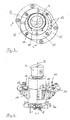
- the present invention is based on an embodiment of the FIGS. 1 to 4 explained in more detail.
- the invention may include features shown here individually as well as in any meaningful combination.
- FIG. 1 a turntable 2 of a superstructure and a ring gear 1 of a lower carriage is shown, wherein the turntable 2 about the rotational axis D relative to the ring gear 1 is rotatably movable. If such a rotation takes place, the screwed firmly on the turntable 2 Drehwinkelgeberan Samuel is moved in its storage 5 about the rotation axis D, wherein the rolling element 3 rolls with its peripheral surface 3 a on a corresponding peripheral surface 1 a of the ring gear 1.
- the peripheral surfaces 1a and 3a are in this case corresponding Stirnradveriereept.
- the rolling element 3 rotates about the axis of rotation R and is screwed to the rotary encoder 4 so that only a rotational movement about the axis R is possible.
- the housing of the rotary encoder 4 is firmly held by the eccentric 10.
- the turntable 2 also has a through hole 9, in which the eccentric 10 is embedded.
- the base 15 is clamped by the clamping ring 12 and the eccentric 10, so that the eccentric together with the clamping ring 12 relative to the base 10 can not be rotated. Since the base 15 is screwed to the turntable 2, and the eccentric is fixedly mounted in the turntable 2.
- FIG. 2 shows a perspective view of the rotary encoder assembly with the eccentric 10, the base 15, which is rotatable about the rotation axis R rolling element 3 with the circumferential toothing 3A. Also to be seen is the screw 8 of the elastic rolling element 3, wherein a further not designated inelastic disc allows the screwing of the elastic rolling element 3 to the input shaft of the rotary encoder.
- a plan view of the Drehwinkelgeberan angel invention is the eccentricity e between the first axis of rotation about which the rolling element 3 rotates when rolling over its teeth 3A, and the second axis of rotation E, by which the eccentric 10 can rotate in the bore 9, unless this is clamped against rotation with the clamping ring 12 and the screw 14 on the base 15. Also visible are the elongated holes 13, which allow a rotation of the eccentric together with the clamping ring 12 and the screw 14, if the screw 14 has been solved.
- FIG. 4 From the FIG. 4 is a sectional view along AA from the FIG. 3 to see.
- the rolling element 3 here has no inelastic, circumferential ring, but the elastic part 7 extends to the rolling teeth 3A and comes into direct contact with the teeth 1A of the ring gear.
- the housing of the rotary encoder has a kind of key surface which engages in a further not designated corresponding holding surface of the eccentric 10 and prevents rotation of the rotary encoder 4 relative to the eccentric 10. This is supported by a further unspecified screw.
Landscapes
- Engineering & Computer Science (AREA)
- Mechanical Engineering (AREA)
- Rolling Contact Bearings (AREA)
- Rolls And Other Rotary Bodies (AREA)
- Control And Safety Of Cranes (AREA)
- Replacement Of Web Rolls (AREA)
- Retarders (AREA)
- Transmission And Conversion Of Sensor Element Output (AREA)
Claims (9)
- Ensemble de capteur d'angle de rotation pour une liaison rotative sur une machine-outil, notamment pour une liaison rotative d'une grue, entre deux éléments rotatifs (1, 2), avec un élément de roulement (3) élastique, qui en accouplement au capteur d'angle de rotation (4), roule sur le premier élément rotatif (1) par l'intermédiaire de sa surface périphérique (3a), le capteur d'angle de rotation (4) détectant le mouvement de rotation autour de l'axe de rotation (R) de l'élément de roulement (3) et l'élément de roulement (3) étant maintenu de manière réglable en rotation par le deuxième élément rotatif (2) au moyen d'un palier (5) autour d'un deuxième axe de rotation (E) différent de l'axe de rotation (R), pour ainsi faire varier la distance entre l'élément de roulement (3) et le premier élément rotatif (1), le palier (5) comportant un dispositif de blocage (11),avec lequel le maintien réglable de l'élément de roulement (3) peut être bloqué.
- Ensemble de capteur d'angle de rotation selon la revendication 1, dans lequel l'élément de roulement (3) est un pignon (3), lequel vient en prise dans la denture périphérique (1a) d'une couronne dentée de la liaison rotative sur le premier élément rotatif (1) et qui roule sur lui.
- Ensemble de capteur d'angle de rotation selon la revendication 1 ou 2 , dans lequel le deuxième axe de rotation (E) est aligné parallèlement à l'axe de rotation (R) de l'élément de roulement (3) et/ou parallèlement à l'axe de rotation (D) entre le premier et le deuxième élément rotatif (1, 2).
- Ensemble de capteur d'angle de rotation selon l'une des revendications 1 à 3, dans lequel l'élément de roulement (3) comprend un matériau élastique, notamment une matière synthétique, en particulier du caoutchouc.
- Ensemble de capteur d'angle de rotation selon la revendication 4, dans lequel la surface périphérique (3a) de l'élément de roulement (3), qui constitue notamment une partie d'une pièce annulaire inélastique, s'accouple à un élément d'entraînement (8) au moyen d'un élément élastique (6), notamment d'un insert (6), l'élément d'entraînement (8) transmettant le mouvement de rotation de l'élément de roulement (3) au capteur d'angle de rotation (4).
- Ensemble de capteur d'angle de rotation selon l'une des revendications 1 à 5, dans lequel le palier (5) comprend un réceptacle (9) pour un excentrique (10) sur ou dans le deuxième élément rotatif (2), qui supporte l'excentrique (10) autour du deuxième axe de rotation (E), et dans lequel l'excentrique (10) supporte l'élément de roulement (3) autour de l'axe de rotation (R) de l'élément de roulement (3).
- Ensemble de capteur d'angle de rotation selon la revendication 6, dans lequel le réceptacle (9) constitue un alésage traversant dans le deuxième élément rotatif (2), notamment dans la table rotative (2).
- Ensemble de capteur d'angle de rotation selon la revendication 6 ou 7, dans lequel l'excentrique (10) supporte l'élément de roulement (3) qui s'accouple au capteur d'angle de rotation (4) au moyen du capteur d'angle de rotation (4), et dans lequel l'excentrique (10) enserre notamment le capteur d'angle de rotation (4) autour de la circonférence.
- Ensemble de capteur d'angle de rotation selon l'une des revendications 1 à 8, dans lequel le dispositif de blocage (11) comprend une bague de serrage (12) qui est vissée sur l'excentrique (10), et serre ainsi une base (15) disposée entre la bague de serrage (12) et l'excentrique (10), comportant des trous oblongs (13) pour le vissage (14) et étant fixée sur le deuxième élément rotatif (2).
Applications Claiming Priority (1)
| Application Number | Priority Date | Filing Date | Title |
|---|---|---|---|
| DE202010011721U DE202010011721U1 (de) | 2010-08-24 | 2010-08-24 | Radialspielausgleichende Drehwinkelgeberanordnung |
Publications (3)
| Publication Number | Publication Date |
|---|---|
| EP2423151A1 EP2423151A1 (fr) | 2012-02-29 |
| EP2423151B1 EP2423151B1 (fr) | 2015-11-11 |
| EP2423151B2 true EP2423151B2 (fr) | 2019-05-01 |
Family
ID=42994219
Family Applications (1)
| Application Number | Title | Priority Date | Filing Date |
|---|---|---|---|
| EP11175629.2A Not-in-force EP2423151B2 (fr) | 2010-08-24 | 2011-07-27 | Dispositif de capteur angulaire de rotation à équilibrage de jeu radial |
Country Status (4)
| Country | Link |
|---|---|
| US (1) | US8572855B2 (fr) |
| EP (1) | EP2423151B2 (fr) |
| CA (1) | CA2748874C (fr) |
| DE (1) | DE202010011721U1 (fr) |
Families Citing this family (9)
| Publication number | Priority date | Publication date | Assignee | Title |
|---|---|---|---|---|
| DE102010012888B4 (de) * | 2010-03-26 | 2018-02-08 | Liebherr-Werk Ehingen Gmbh | Baumaschine |
| DE202010011721U1 (de) * | 2010-08-24 | 2010-10-21 | Manitowoc Crane Group France Sas | Radialspielausgleichende Drehwinkelgeberanordnung |
| CN103557313A (zh) * | 2013-10-31 | 2014-02-05 | 北方重工集团有限公司 | 一种回转驱动中心位置微调装置 |
| DE112014005496T8 (de) * | 2014-06-16 | 2016-10-06 | Xcmg Xuzhou Truck Mounted Crane Co., Ltd. | Detektionsvorrichtung, -System und Detektionsverfahren eines Drehbereiches |
| CN104555738B (zh) * | 2015-01-19 | 2017-11-10 | 浙江三一装备有限公司 | 起重机及其回转角度测量装置 |
| CN107304026A (zh) * | 2016-04-18 | 2017-10-31 | 上海船厂船舶有限公司 | 行走机构 |
| CN107381363A (zh) * | 2017-08-08 | 2017-11-24 | 国家电网公司 | 桥机并车中的位移数据采集系统 |
| CN109019341B (zh) * | 2018-08-14 | 2020-07-28 | 苏州汇川技术有限公司 | 塔式起重机回转控制系统以及方法 |
| IT201900015388A1 (it) * | 2019-09-02 | 2021-03-02 | Fassi Gru S P A | Gru a ralla con rotazione limitata |
Family Cites Families (16)
| Publication number | Priority date | Publication date | Assignee | Title |
|---|---|---|---|---|
| US3629635A (en) | 1970-06-01 | 1971-12-21 | Bendix Corp | Wheel-speed sensor for an adaptive braking system |
| DD159516A3 (de) | 1981-03-18 | 1983-03-16 | Gunter Planitzer | Messwertgeber |
| US5045034A (en) * | 1990-05-31 | 1991-09-03 | Aurora Crane Corporation | Adjustable antibacklash gear system |
| DE4028931A1 (de) * | 1990-09-12 | 1992-03-19 | Bosch Gmbh Robert | Drehstellungsgeber |
| DE4240615C2 (de) * | 1992-12-03 | 2001-11-15 | Bosch Gmbh Robert | Stellungsgeber |
| GB9225971D0 (en) * | 1992-12-12 | 1993-02-10 | Penny & Giles Blackwood Ltd | Rotary transducer |
| DE19624074A1 (de) | 1996-06-17 | 1997-12-18 | Bayerische Motoren Werke Ag | Zahnradgetriebe mit exzentrisch gelagerter Welle, beispielsweise für den Ausgleichswellen-Antrieb einer Brennkraftmaschine |
| US6035736A (en) | 1997-11-07 | 2000-03-14 | Caterpillar Inc. | Adjustable pinion gear mounting arrangement |
| DE19904471B4 (de) * | 1999-02-04 | 2011-03-31 | Dr. Johannes Heidenhain Gmbh | Drehgeber |
| US6374664B1 (en) * | 2000-01-21 | 2002-04-23 | Delphi Technologies, Inc. | Rotary position transducer and method |
| DE102004022770B4 (de) * | 2004-05-05 | 2007-10-18 | Koenig & Bauer Aktiengesellschaft | Befestigung eines Drehgebers |
| JP2006144305A (ja) * | 2004-11-17 | 2006-06-08 | Kayaba Ind Co Ltd | 旋回機構。 |
| FR2907109B1 (fr) | 2006-10-12 | 2008-12-19 | Potain Soc Par Actions Simplif | Indicateur de position de fleche pour grue |
| EP1953503B1 (fr) * | 2007-01-05 | 2010-03-10 | SICK STEGMANN GmbH | Encodeur |
| DE102008025027B4 (de) * | 2008-05-24 | 2021-05-20 | Koenig & Bauer Ag | Verfahren und Vorrichtung zur Kompensierung von Rundlauffehlern eines Drehwinkel erfassenden Sensors |
| DE202010011721U1 (de) * | 2010-08-24 | 2010-10-21 | Manitowoc Crane Group France Sas | Radialspielausgleichende Drehwinkelgeberanordnung |
-
2010
- 2010-08-24 DE DE202010011721U patent/DE202010011721U1/de not_active Expired - Lifetime
-
2011
- 2011-07-27 EP EP11175629.2A patent/EP2423151B2/fr not_active Not-in-force
- 2011-08-12 CA CA2748874A patent/CA2748874C/fr not_active Expired - Fee Related
- 2011-08-23 US US13/215,850 patent/US8572855B2/en not_active Expired - Fee Related
Non-Patent Citations (1)
| Title |
|---|
| <<<N O N - C I T E D D O C U M E N T>>> Anlagenvolut der Fernsteuergeräte FSG Kurt Oelsch GmbH † |
Also Published As
| Publication number | Publication date |
|---|---|
| CA2748874A1 (fr) | 2012-02-24 |
| US20120117810A1 (en) | 2012-05-17 |
| DE202010011721U1 (de) | 2010-10-21 |
| EP2423151B1 (fr) | 2015-11-11 |
| EP2423151A1 (fr) | 2012-02-29 |
| CA2748874C (fr) | 2014-12-23 |
| US8572855B2 (en) | 2013-11-05 |
Similar Documents
| Publication | Publication Date | Title |
|---|---|---|
| EP2423151B2 (fr) | Dispositif de capteur angulaire de rotation à équilibrage de jeu radial | |
| EP2951078B1 (fr) | Colonne de direction pour véhicule automobile | |
| EP2861879B1 (fr) | Palier lisse pour un arbre de direction | |
| EP2855237B1 (fr) | Colonne de direction pour un véhicule automobile | |
| DE4126535C2 (de) | Walze zum Führen und Strecken von Bändern und/oder Folienbahnen | |
| EP3010781B1 (fr) | Compensation de jeu pour un palier de pignon | |
| DE202010016197U1 (de) | Spielfrei laufendes Zahnrad | |
| EP2115822B1 (fr) | Connecteur à fiches coudé à direction de départ variable | |
| DE4434166C2 (de) | Vorrichtung zum Ausgleich der Unwucht eines Bohrkopfes | |
| DE4220879A1 (de) | Riemenspannvorrichtung | |
| EP0802048B1 (fr) | Capteur de rotation pour un cylindre d'une machine à imprimer | |
| EP3544878A1 (fr) | Mécanisme de direction et système de direction | |
| EP3541685A1 (fr) | Système de direction | |
| EP2881604B1 (fr) | Dispositif de fixation destiné à la fixation concentrique d'un arbre sur un arbre d'encodeur et système de rétroaction de moteur doté d'une telle fixation | |
| WO2015124466A1 (fr) | Direction à crémaillère et ensemble d'amortissement de butée de fin de course pour ladite direction à crémaillère | |
| EP1978275B1 (fr) | Articulation, en particulier sur une plateforme pivotante entre un wagon avant et un wagon arrière d'un bus à plateforme pivotante | |
| EP2072201B1 (fr) | Palpeur d'angle | |
| WO2021052526A1 (fr) | Vis d'entraînement à roulement planétaire | |
| DE102008039390B4 (de) | Fehlercompensierende Schneckenfördervorrichtung unter Verwendung von Lagerungen | |
| DE102009016187B4 (de) | Lager für eine Vorrichtung zur Erzeugung eines Schwenkmoments | |
| EP3850246B1 (fr) | Transmission | |
| DE102021202509A1 (de) | Steer-by-Wire-Lenksystem | |
| DE9318878U1 (de) | Riemenspanner mit Doppelexzenter | |
| EP1989454B1 (fr) | Cylindre | |
| WO2018206305A1 (fr) | Palier fixe, mécanisme de direction et système de direction |
Legal Events
| Date | Code | Title | Description |
|---|---|---|---|
| AK | Designated contracting states |
Kind code of ref document: A1 Designated state(s): AL AT BE BG CH CY CZ DE DK EE ES FI FR GB GR HR HU IE IS IT LI LT LU LV MC MK MT NL NO PL PT RO RS SE SI SK SM TR |
|
| AX | Request for extension of the european patent |
Extension state: BA ME |
|
| PUAI | Public reference made under article 153(3) epc to a published international application that has entered the european phase |
Free format text: ORIGINAL CODE: 0009012 |
|
| 17P | Request for examination filed |
Effective date: 20120424 |
|
| RIC1 | Information provided on ipc code assigned before grant |
Ipc: B66C 23/84 20060101AFI20130130BHEP |
|
| RAP1 | Party data changed (applicant data changed or rights of an application transferred) |
Owner name: MANITOWOC CRANE GROUP FRANCE SAS |
|
| GRAP | Despatch of communication of intention to grant a patent |
Free format text: ORIGINAL CODE: EPIDOSNIGR1 |
|
| INTG | Intention to grant announced |
Effective date: 20150603 |
|
| GRAS | Grant fee paid |
Free format text: ORIGINAL CODE: EPIDOSNIGR3 |
|
| GRAA | (expected) grant |
Free format text: ORIGINAL CODE: 0009210 |
|
| AK | Designated contracting states |
Kind code of ref document: B1 Designated state(s): AL AT BE BG CH CY CZ DE DK EE ES FI FR GB GR HR HU IE IS IT LI LT LU LV MC MK MT NL NO PL PT RO RS SE SI SK SM TR |
|
| REG | Reference to a national code |
Ref country code: GB Ref legal event code: FG4D Free format text: NOT ENGLISH |
|
| REG | Reference to a national code |
Ref country code: CH Ref legal event code: EP |
|
| REG | Reference to a national code |
Ref country code: IE Ref legal event code: FG4D Free format text: LANGUAGE OF EP DOCUMENT: GERMAN |
|
| REG | Reference to a national code |
Ref country code: AT Ref legal event code: REF Ref document number: 760323 Country of ref document: AT Kind code of ref document: T Effective date: 20151215 |
|
| REG | Reference to a national code |
Ref country code: DE Ref legal event code: R096 Ref document number: 502011008321 Country of ref document: DE |
|
| REG | Reference to a national code |
Ref country code: LT Ref legal event code: MG4D |
|
| REG | Reference to a national code |
Ref country code: NL Ref legal event code: MP Effective date: 20160211 |
|
| PG25 | Lapsed in a contracting state [announced via postgrant information from national office to epo] |
Ref country code: IT Free format text: LAPSE BECAUSE OF FAILURE TO SUBMIT A TRANSLATION OF THE DESCRIPTION OR TO PAY THE FEE WITHIN THE PRESCRIBED TIME-LIMIT Effective date: 20151111 Ref country code: NL Free format text: LAPSE BECAUSE OF FAILURE TO SUBMIT A TRANSLATION OF THE DESCRIPTION OR TO PAY THE FEE WITHIN THE PRESCRIBED TIME-LIMIT Effective date: 20151111 Ref country code: HR Free format text: LAPSE BECAUSE OF FAILURE TO SUBMIT A TRANSLATION OF THE DESCRIPTION OR TO PAY THE FEE WITHIN THE PRESCRIBED TIME-LIMIT Effective date: 20151111 Ref country code: IS Free format text: LAPSE BECAUSE OF FAILURE TO SUBMIT A TRANSLATION OF THE DESCRIPTION OR TO PAY THE FEE WITHIN THE PRESCRIBED TIME-LIMIT Effective date: 20160311 Ref country code: NO Free format text: LAPSE BECAUSE OF FAILURE TO SUBMIT A TRANSLATION OF THE DESCRIPTION OR TO PAY THE FEE WITHIN THE PRESCRIBED TIME-LIMIT Effective date: 20160211 Ref country code: LT Free format text: LAPSE BECAUSE OF FAILURE TO SUBMIT A TRANSLATION OF THE DESCRIPTION OR TO PAY THE FEE WITHIN THE PRESCRIBED TIME-LIMIT Effective date: 20151111 Ref country code: ES Free format text: LAPSE BECAUSE OF FAILURE TO SUBMIT A TRANSLATION OF THE DESCRIPTION OR TO PAY THE FEE WITHIN THE PRESCRIBED TIME-LIMIT Effective date: 20151111 |
|
| PG25 | Lapsed in a contracting state [announced via postgrant information from national office to epo] |
Ref country code: GR Free format text: LAPSE BECAUSE OF FAILURE TO SUBMIT A TRANSLATION OF THE DESCRIPTION OR TO PAY THE FEE WITHIN THE PRESCRIBED TIME-LIMIT Effective date: 20160212 Ref country code: LV Free format text: LAPSE BECAUSE OF FAILURE TO SUBMIT A TRANSLATION OF THE DESCRIPTION OR TO PAY THE FEE WITHIN THE PRESCRIBED TIME-LIMIT Effective date: 20151111 Ref country code: PL Free format text: LAPSE BECAUSE OF FAILURE TO SUBMIT A TRANSLATION OF THE DESCRIPTION OR TO PAY THE FEE WITHIN THE PRESCRIBED TIME-LIMIT Effective date: 20151111 Ref country code: FI Free format text: LAPSE BECAUSE OF FAILURE TO SUBMIT A TRANSLATION OF THE DESCRIPTION OR TO PAY THE FEE WITHIN THE PRESCRIBED TIME-LIMIT Effective date: 20151111 Ref country code: SE Free format text: LAPSE BECAUSE OF FAILURE TO SUBMIT A TRANSLATION OF THE DESCRIPTION OR TO PAY THE FEE WITHIN THE PRESCRIBED TIME-LIMIT Effective date: 20151111 Ref country code: RS Free format text: LAPSE BECAUSE OF FAILURE TO SUBMIT A TRANSLATION OF THE DESCRIPTION OR TO PAY THE FEE WITHIN THE PRESCRIBED TIME-LIMIT Effective date: 20151111 Ref country code: PT Free format text: LAPSE BECAUSE OF FAILURE TO SUBMIT A TRANSLATION OF THE DESCRIPTION OR TO PAY THE FEE WITHIN THE PRESCRIBED TIME-LIMIT Effective date: 20160311 |
|
| REG | Reference to a national code |
Ref country code: FR Ref legal event code: PLFP Year of fee payment: 6 |
|
| REG | Reference to a national code |
Ref country code: DE Ref legal event code: R026 Ref document number: 502011008321 Country of ref document: DE |
|
| PG25 | Lapsed in a contracting state [announced via postgrant information from national office to epo] |
Ref country code: CZ Free format text: LAPSE BECAUSE OF FAILURE TO SUBMIT A TRANSLATION OF THE DESCRIPTION OR TO PAY THE FEE WITHIN THE PRESCRIBED TIME-LIMIT Effective date: 20151111 |
|
| PLBI | Opposition filed |
Free format text: ORIGINAL CODE: 0009260 |
|
| PG25 | Lapsed in a contracting state [announced via postgrant information from national office to epo] |
Ref country code: SM Free format text: LAPSE BECAUSE OF FAILURE TO SUBMIT A TRANSLATION OF THE DESCRIPTION OR TO PAY THE FEE WITHIN THE PRESCRIBED TIME-LIMIT Effective date: 20151111 Ref country code: RO Free format text: LAPSE BECAUSE OF FAILURE TO SUBMIT A TRANSLATION OF THE DESCRIPTION OR TO PAY THE FEE WITHIN THE PRESCRIBED TIME-LIMIT Effective date: 20151111 Ref country code: SK Free format text: LAPSE BECAUSE OF FAILURE TO SUBMIT A TRANSLATION OF THE DESCRIPTION OR TO PAY THE FEE WITHIN THE PRESCRIBED TIME-LIMIT Effective date: 20151111 Ref country code: DK Free format text: LAPSE BECAUSE OF FAILURE TO SUBMIT A TRANSLATION OF THE DESCRIPTION OR TO PAY THE FEE WITHIN THE PRESCRIBED TIME-LIMIT Effective date: 20151111 Ref country code: EE Free format text: LAPSE BECAUSE OF FAILURE TO SUBMIT A TRANSLATION OF THE DESCRIPTION OR TO PAY THE FEE WITHIN THE PRESCRIBED TIME-LIMIT Effective date: 20151111 |
|
| 26 | Opposition filed |
Opponent name: LIEBHERR-WERK EHINGEN GMBH Effective date: 20160727 |
|
| PLAX | Notice of opposition and request to file observation + time limit sent |
Free format text: ORIGINAL CODE: EPIDOSNOBS2 |
|
| PG25 | Lapsed in a contracting state [announced via postgrant information from national office to epo] |
Ref country code: SI Free format text: LAPSE BECAUSE OF FAILURE TO SUBMIT A TRANSLATION OF THE DESCRIPTION OR TO PAY THE FEE WITHIN THE PRESCRIBED TIME-LIMIT Effective date: 20151111 |
|
| PLBB | Reply of patent proprietor to notice(s) of opposition received |
Free format text: ORIGINAL CODE: EPIDOSNOBS3 |
|
| PG25 | Lapsed in a contracting state [announced via postgrant information from national office to epo] |
Ref country code: BE Free format text: LAPSE BECAUSE OF NON-PAYMENT OF DUE FEES Effective date: 20160731 |
|
| REG | Reference to a national code |
Ref country code: CH Ref legal event code: PL |
|
| GBPC | Gb: european patent ceased through non-payment of renewal fee |
Effective date: 20160727 |
|
| PG25 | Lapsed in a contracting state [announced via postgrant information from national office to epo] |
Ref country code: MC Free format text: LAPSE BECAUSE OF FAILURE TO SUBMIT A TRANSLATION OF THE DESCRIPTION OR TO PAY THE FEE WITHIN THE PRESCRIBED TIME-LIMIT Effective date: 20151111 |
|
| PG25 | Lapsed in a contracting state [announced via postgrant information from national office to epo] |
Ref country code: LI Free format text: LAPSE BECAUSE OF NON-PAYMENT OF DUE FEES Effective date: 20160731 Ref country code: CH Free format text: LAPSE BECAUSE OF NON-PAYMENT OF DUE FEES Effective date: 20160731 |
|
| REG | Reference to a national code |
Ref country code: IE Ref legal event code: MM4A |
|
| PG25 | Lapsed in a contracting state [announced via postgrant information from national office to epo] |
Ref country code: GB Free format text: LAPSE BECAUSE OF NON-PAYMENT OF DUE FEES Effective date: 20160727 |
|
| REG | Reference to a national code |
Ref country code: FR Ref legal event code: PLFP Year of fee payment: 7 |
|
| PG25 | Lapsed in a contracting state [announced via postgrant information from national office to epo] |
Ref country code: IE Free format text: LAPSE BECAUSE OF NON-PAYMENT OF DUE FEES Effective date: 20160727 |
|
| PG25 | Lapsed in a contracting state [announced via postgrant information from national office to epo] |
Ref country code: LU Free format text: LAPSE BECAUSE OF NON-PAYMENT OF DUE FEES Effective date: 20160727 |
|
| PG25 | Lapsed in a contracting state [announced via postgrant information from national office to epo] |
Ref country code: HU Free format text: LAPSE BECAUSE OF FAILURE TO SUBMIT A TRANSLATION OF THE DESCRIPTION OR TO PAY THE FEE WITHIN THE PRESCRIBED TIME-LIMIT; INVALID AB INITIO Effective date: 20110727 Ref country code: CY Free format text: LAPSE BECAUSE OF FAILURE TO SUBMIT A TRANSLATION OF THE DESCRIPTION OR TO PAY THE FEE WITHIN THE PRESCRIBED TIME-LIMIT Effective date: 20151111 |
|
| PG25 | Lapsed in a contracting state [announced via postgrant information from national office to epo] |
Ref country code: MT Free format text: LAPSE BECAUSE OF FAILURE TO SUBMIT A TRANSLATION OF THE DESCRIPTION OR TO PAY THE FEE WITHIN THE PRESCRIBED TIME-LIMIT Effective date: 20151111 Ref country code: TR Free format text: LAPSE BECAUSE OF FAILURE TO SUBMIT A TRANSLATION OF THE DESCRIPTION OR TO PAY THE FEE WITHIN THE PRESCRIBED TIME-LIMIT Effective date: 20151111 Ref country code: MK Free format text: LAPSE BECAUSE OF FAILURE TO SUBMIT A TRANSLATION OF THE DESCRIPTION OR TO PAY THE FEE WITHIN THE PRESCRIBED TIME-LIMIT Effective date: 20151111 |
|
| REG | Reference to a national code |
Ref country code: FR Ref legal event code: PLFP Year of fee payment: 8 |
|
| PG25 | Lapsed in a contracting state [announced via postgrant information from national office to epo] |
Ref country code: BG Free format text: LAPSE BECAUSE OF FAILURE TO SUBMIT A TRANSLATION OF THE DESCRIPTION OR TO PAY THE FEE WITHIN THE PRESCRIBED TIME-LIMIT Effective date: 20151111 |
|
| PG25 | Lapsed in a contracting state [announced via postgrant information from national office to epo] |
Ref country code: AL Free format text: LAPSE BECAUSE OF FAILURE TO SUBMIT A TRANSLATION OF THE DESCRIPTION OR TO PAY THE FEE WITHIN THE PRESCRIBED TIME-LIMIT Effective date: 20151111 |
|
| PUAH | Patent maintained in amended form |
Free format text: ORIGINAL CODE: 0009272 |
|
| STAA | Information on the status of an ep patent application or granted ep patent |
Free format text: STATUS: PATENT MAINTAINED AS AMENDED |
|
| 27A | Patent maintained in amended form |
Effective date: 20190501 |
|
| AK | Designated contracting states |
Kind code of ref document: B2 Designated state(s): AL AT BE BG CH CY CZ DE DK EE ES FI FR GB GR HR HU IE IS IT LI LT LU LV MC MK MT NL NO PL PT RO RS SE SI SK SM TR |
|
| REG | Reference to a national code |
Ref country code: DE Ref legal event code: R102 Ref document number: 502011008321 Country of ref document: DE |
|
| PGFP | Annual fee paid to national office [announced via postgrant information from national office to epo] |
Ref country code: DE Payment date: 20190719 Year of fee payment: 9 Ref country code: FR Payment date: 20190719 Year of fee payment: 9 |
|
| PGFP | Annual fee paid to national office [announced via postgrant information from national office to epo] |
Ref country code: AT Payment date: 20190722 Year of fee payment: 9 |
|
| REG | Reference to a national code |
Ref country code: DE Ref legal event code: R119 Ref document number: 502011008321 Country of ref document: DE |
|
| REG | Reference to a national code |
Ref country code: AT Ref legal event code: MM01 Ref document number: 760323 Country of ref document: AT Kind code of ref document: T Effective date: 20200727 |
|
| PG25 | Lapsed in a contracting state [announced via postgrant information from national office to epo] |
Ref country code: FR Free format text: LAPSE BECAUSE OF NON-PAYMENT OF DUE FEES Effective date: 20200731 |
|
| PG25 | Lapsed in a contracting state [announced via postgrant information from national office to epo] |
Ref country code: DE Free format text: LAPSE BECAUSE OF NON-PAYMENT OF DUE FEES Effective date: 20210202 Ref country code: AT Free format text: LAPSE BECAUSE OF NON-PAYMENT OF DUE FEES Effective date: 20200727 |