EP2423432A2 - Verankerungsvorrichtung und Verfahren zu ihrer Verwendung - Google Patents
Verankerungsvorrichtung und Verfahren zu ihrer Verwendung Download PDFInfo
- Publication number
- EP2423432A2 EP2423432A2 EP11167023A EP11167023A EP2423432A2 EP 2423432 A2 EP2423432 A2 EP 2423432A2 EP 11167023 A EP11167023 A EP 11167023A EP 11167023 A EP11167023 A EP 11167023A EP 2423432 A2 EP2423432 A2 EP 2423432A2
- Authority
- EP
- European Patent Office
- Prior art keywords
- anchor
- screw
- tubular member
- nut
- hole
- Prior art date
- Legal status (The legal status is an assumption and is not a legal conclusion. Google has not performed a legal analysis and makes no representation as to the accuracy of the status listed.)
- Granted
Links
- 238000000034 method Methods 0.000 title description 24
- 238000004873 anchoring Methods 0.000 title description 19
- 238000013459 approach Methods 0.000 claims abstract description 26
- 238000003780 insertion Methods 0.000 claims abstract description 10
- 230000037431 insertion Effects 0.000 claims abstract description 10
- 230000003068 static effect Effects 0.000 claims description 14
- 239000000463 material Substances 0.000 claims description 3
- 230000008569 process Effects 0.000 description 6
- 230000000694 effects Effects 0.000 description 4
- 230000008901 benefit Effects 0.000 description 3
- 238000005476 soldering Methods 0.000 description 3
- 230000007480 spreading Effects 0.000 description 3
- XEEYBQQBJWHFJM-UHFFFAOYSA-N Iron Chemical compound [Fe] XEEYBQQBJWHFJM-UHFFFAOYSA-N 0.000 description 2
- 238000009434 installation Methods 0.000 description 2
- 230000003993 interaction Effects 0.000 description 2
- 238000007665 sagging Methods 0.000 description 2
- RYGMFSIKBFXOCR-UHFFFAOYSA-N Copper Chemical compound [Cu] RYGMFSIKBFXOCR-UHFFFAOYSA-N 0.000 description 1
- 229910000831 Steel Inorganic materials 0.000 description 1
- 230000009471 action Effects 0.000 description 1
- 230000006978 adaptation Effects 0.000 description 1
- 238000004026 adhesive bonding Methods 0.000 description 1
- XAGFODPZIPBFFR-UHFFFAOYSA-N aluminium Chemical compound [Al] XAGFODPZIPBFFR-UHFFFAOYSA-N 0.000 description 1
- 229910052782 aluminium Inorganic materials 0.000 description 1
- 230000009286 beneficial effect Effects 0.000 description 1
- 239000011449 brick Substances 0.000 description 1
- 238000010276 construction Methods 0.000 description 1
- 229910052802 copper Inorganic materials 0.000 description 1
- 239000010949 copper Substances 0.000 description 1
- 229910052602 gypsum Inorganic materials 0.000 description 1
- 239000010440 gypsum Substances 0.000 description 1
- 229910052742 iron Inorganic materials 0.000 description 1
- 238000012986 modification Methods 0.000 description 1
- 230000004048 modification Effects 0.000 description 1
- 239000010959 steel Substances 0.000 description 1
- 239000004575 stone Substances 0.000 description 1
- 238000003466 welding Methods 0.000 description 1
Images





Classifications
-
- F—MECHANICAL ENGINEERING; LIGHTING; HEATING; WEAPONS; BLASTING
- F16—ENGINEERING ELEMENTS AND UNITS; GENERAL MEASURES FOR PRODUCING AND MAINTAINING EFFECTIVE FUNCTIONING OF MACHINES OR INSTALLATIONS; THERMAL INSULATION IN GENERAL
- F16B—DEVICES FOR FASTENING OR SECURING CONSTRUCTIONAL ELEMENTS OR MACHINE PARTS TOGETHER, e.g. NAILS, BOLTS, CIRCLIPS, CLAMPS, CLIPS OR WEDGES; JOINTS OR JOINTING
- F16B13/00—Dowels or other devices fastened in walls or the like by inserting them in holes made therein for that purpose
- F16B13/04—Dowels or other devices fastened in walls or the like by inserting them in holes made therein for that purpose with parts gripping in the hole or behind the reverse side of the wall after inserting from the front
- F16B13/08—Dowels or other devices fastened in walls or the like by inserting them in holes made therein for that purpose with parts gripping in the hole or behind the reverse side of the wall after inserting from the front with separate or non-separate gripping parts moved into their final position in relation to the body of the device without further manual operation
- F16B13/0866—Dowels or other devices fastened in walls or the like by inserting them in holes made therein for that purpose with parts gripping in the hole or behind the reverse side of the wall after inserting from the front with separate or non-separate gripping parts moved into their final position in relation to the body of the device without further manual operation with prongs penetrating into the wall of the hole by a retractile movement of a threaded member
-
- E—FIXED CONSTRUCTIONS
- E21—EARTH OR ROCK DRILLING; MINING
- E21D—SHAFTS; TUNNELS; GALLERIES; LARGE UNDERGROUND CHAMBERS
- E21D21/00—Anchoring-bolts for roof, floor in galleries or longwall working, or shaft-lining protection
- E21D21/008—Anchoring or tensioning means
Definitions
- the present invention generally pertains to an apparatus and method for anchoring devices. More specifically to it relates to an expandable anchor apparatus and a method to use the anchor such that the anchor is anchored in a pre-formed hole.
- Expansion anchors for mounting in concrete and other strata have taken on a variety of methods and configurations through the years.
- Expansion anchors of different types are provided in the prior art.
- One of these consists of a plastic sleeve having an elongated neck provided with a stop which holds an object at an adjustable distance from a support structure in which the sleeve is mounted.
- the stop is in form of a nut that can be screwed onto the external thread provided on the neck.
- the screw which is threaded into the sleeve to expand the same has a head between which and the nut the object to be affixed is held.
- US Patent 6,986,623 discloses an improved mine roof bolt.
- the mine roof bolt comprises a bolt portion having a camming nut rigidly fixed to it and a threaded end and an expansion shell having a central threaded nut with wedge fingers extending from it.
- the expansion shell is threaded onto the threaded section of the bolt. Turning the bolt while it is in a hole causes the expansion shell to move along the bolt and brings the wedge fingers into contact with the camming nut, spreading the wedge fingers into contact with the hole sides. As the turning of the bolt continues, the relative movement of the camming nut and wedge fingers increases the wedging effect within the hole until the bolt is anchored in the hole.
- the anchor of this patent suffers from a critical limitation. This limitation is in the process of the anchoring.
- the present invention discloses an anchor apparatus for insertion into a pre-formed hole in an object of interest for permanent embedment in the hole.
- the apparatus comprises:
- the anchor and the tubular member disposed on the screw with sufficiently loose fit between the screw head and the nut such that the distal part of the tubular member spreads apart the fixing petals of the anchor when the screw head and the nut approach each other.
- the proximal part of the tubular member comprises a gripping part adapted for gripping by a user's tool, so that the anchor is prevented from turning around an axis of the screw due to static friction between the tubular member and the petals while the screw head and the nut approach each other.
- the present invention also discloses an anchor apparatus, wherein the nut and the distal part of the anchor are interconnected between each other. Further wherein the screw head and the nut approach each while the screw is screwed into the nut.
- the present invention also discloses an anchor apparatus, wherein the screw head and the distal part of the anchor and interconnected between each other, further wherein the screw head and the nut approach each while the nut is screwed on the nut.
- the present invention also discloses an anchor apparatus, wherein said interconnected is selected from a group consisting of: glued, attached, bound, fastened, soldered, welded or any combination thereof.
- the present invention also discloses an anchor apparatus, wherein the object of interest is a wall.
- the present invention also discloses an anchor apparatus, wherein the wall is a selected from a group consisting of a concrete wall, a gypsum wall, a block wall, a brick wall, a stone wall, or any combination thereof.
- the present invention also discloses an anchor apparatus, the distal part of the tubular member has an approximate shape selected from a group consisting of: a conical shape, a cylindrical shape, a spherical shape, a polygonal shape or any combination thereof.
- the present invention also discloses an anchor apparatus, wherein the distal part of the tubular member further comprises sagging guide paths.
- the guide paths are adapted to cause the fixing petals slide across the length of the distal part of the tubular member.
- the present invention also discloses an anchor apparatus, wherein the grasping part has an approximate shape selected from a group consisting of: a conical shape, a cylindrical shape, a polygonal shape or any combination thereof.
- the present invention also discloses an anchor apparatus, wherein the tool comprises at least two parts: a stable part for gripping the grasping part of the tubular member, and a rotating part for rotating the screw head.
- the present invention also discloses an anchor apparatus, wherein the tool comprises at least two parts: a stable part for gripping the grasping part of the tubular member, and a rotating part for rotating the nut.
- the present inventions also discloses an anchor apparatus, wherein the internal sides of the fixing petals and the outside of the distal part of the tubular member are made of materials with a static friction coefficient of between about 0.5 and about 0.8.
- the present invention also discloses an anchor apparatus, wherein the fixing petals and the tubular member are made of material selected from a group consisting of: steel, iron, copper, aluminum, plastic or any combination thereof.
- the present invention also discloses an anchor apparatus further comprising at least one disc adapted to be positioned on the tubular member and to be disposed on the tubular member between the screw head and the proximal part of the anchor.
- the present invention also discloses an anchor apparatus further comprising at least one disc adapted to be positioned on the tubular member and to be disposed on the tubular member between the nut and the proximal part of the anchor.
- the present invention also discloses an anchor apparatus, wherein the object of interest is located between the nut and the proximal part of the anchor.
- the present invention also discloses an anchor apparatus, wherein the object of interest is located between the screw head and the proximal part of the anchor.
- the present invention also discloses an anchor apparatus, wherein the screw or the nut are screwed is by a tool selected from a group consisting of: an adjustable spanner, an extractor, a screwdriver, a plier, a screw tool or any combination thereof.
- the present invention also discloses an anchor apparatus, wherein the object of interest is located between the screw head and the proximal part of the anchor.
- the present invention also discloses an anchor apparatus, wherein the gripping tool is selected from a group consisting of: an adjustable spanner, a plier, a screw tool or any combination thereof.
- the present invention also discloses a method of using an anchor apparatus.
- the method comprises:
- the present invention also discloses a method of using an anchor apparatus.
- the method comprises:
- the present invention also discloses a method of using an anchor apparatus which comprises an additional step of interconnecting the nut and the distal part of the anchor.
- the present invention also discloses a method of using an anchor apparatus which comprises an additional step of interconnecting the screw head and the distal part of the anchor.
- the present invention also discloses a method of using an anchor apparatus, wherein the step of interconnecting is selected from a group consisting of: gluing, attaching, bounding, fastening, soldering, welding or any combination thereof.
- the present invention discloses an anchor apparatus for insertion into a pre-formed hole in an object of interest for permanent embedment in the hole.
- the apparatus comprises:
- the anchor and the tubular member disposed on the screw with sufficiently loose fit between the screw head and the nut such that the distal part of the tubular member spreads apart the fixing petals of the anchor when the screw head and the nut approach each other.
- the proximal part of the tubular member comprises a gripping part adapted for gripping by a user's tool, so that the anchor is prevented from turning around an axis of the screw due to static friction between the tubular member and the petals which is greater than the static friction between the nut and the screw, while the screw head and the nut approach each other.
- the present invention discloses an anchor apparatus for insertion into a pre-formed hole in an object of interest for permanent embedment in the hole.
- the apparatus comprises:
- the anchor and the tubular member disposed on the screw with sufficiently loose fit between the screw head and the nut such that the distal part of the tubular member spreads apart the fixing petals of the anchor when the screw head and the nut approach each other.
- the proximal part of the tubular member comprises a gripping part adapted for gripping by a user's tool, so that the anchor is prevented from turning around an axis of the screw due to static friction between the tubular member and the petals while the screw head and the nut approach each other.
- the expansion of the anchor does not depend on the inner walls of the hole as the anchor does not rotate while being expended inside said hole.
- the initial diameter of the hole can be greater than the initial diameter of the anchor.
- the present invention also discloses an anchor apparatus insertable into a pre-formed hole in an object of interest for permanent fixation in said hole.
- the aforesaid apparatus comprises (a) a rotatable screw provided with a head grippable by a user's screw key; and (b) fixating means.
- the fixating means comprises a pair of extendable anchors including distal and proximal anchors. The anchors are loosely put onto said screw.
- the distal anchor is provided with a portion grippable by an user's key.
- the proximal anchor is provided with a portion threadably connected to said screw.
- the petals are provided with bevels at terminals thereof.
- Each anchor has a portion provided with an equal number of extendable petal-shaped members.
- the petal-shaped portions are face-to-face oriented along to said screw.
- the petal shaped members are provided with internal and outer bevels at terminals thereof.
- the petal shaped members belonging to each anchor provided with said internal and outer bevels in an alternate manner.
- the anchors are angularly oriented such that bevels of petal shaped members disposed contrariwise each other have opposite bevels.
- the rotatable screw is adapted for tying up said anchors such that said petal shaped members having said outside bevels are inserted under said petal shaped members having internal bevels and force said members having internal bevels to spread out aside.
- the present invention also discloses a method of using an anchor apparatus.
- the aforesaid method comprise the steps of: (a) (a) providing an anchor apparatus insertable into a pre-formed hole in an object of interest for permanent fixation in said hole, said apparatus comprising (i) a rotatable screw provided with a head grippable by a user's screw key; and (ii) fixating means; (b) said apparatus further comprises a pair of extendable anchors including distal and proximal anchors; said anchors loosely put onto said screw; said distal anchor provided with a portion grippable by an user's key; said proximal anchor provided with a portion threadably connected to said screw; said petals provided with bevels at terminals thereof; each anchor having a portion provided with an equal number of extendable petal-shaped members; said portions are face-to-face oriented along to said screw; said petal shaped members are provided with internal and outer bevels at terminals thereof; said petal shaped members belonging to each anchor provided with
- said step of fixating said apparatus within said hole further comprises a step of tying up said fixating means comprising a pair of extendable anchors including distal and proximal anchors; said anchors are loosely put onto said screw; said distal anchor is gripped by an user's key; said proximal anchor is threadably connected to said screw; said petals are provided with bevels at terminals thereof; each anchor has a portion provided with an equal number of extendable petal-shaped members; said portions are face-to-face oriented along to said screw; said petal shaped members are provided with internal and outer bevels at terminals thereof; said petal shaped members belonging to each anchor provided with said internal and outer bevels in an alternate manner; said anchors are angularly oriented such that bevels of petal shaped members disposed contrariwise each other have opposite bevels; said petal shaped members having said outside bevels are inserted under said petal shaped members having internal bevels and force said members having internal bevels to spread out aside.
- 'bevel' hereinafter refers to a surface which is not perpendicular to the faces of the piece.
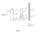
- FIG. 1 where illustrated one aspect of the anchor apparatus of the present invention for insertion into a pre-formed hole in an object of interest for permanent embedment in the hole.
- screw 10 with a screw head 11 and a thread 12.
- the nut 15 is adapted to be threaded on the thread 12 of screw 10.
- the Anchor 20 with a distal part 21 and a proximal part 22 is provided to be received and anchored in the hole.
- anchor 20 comprises three fixing petals 24 extendable from the outer perimeter of the distal part 21 of anchor 20 .
- Pushing tubular member 30 comprises a distal part 31 , a proximal part 32 and a gripping part 33 .
- the distal part of the tubular member 30 adapted to expand the fixing petals 24 of the anchor 20.
- the distal part 31 of the tubular member 30 has a conical outer shape.
- the distal part 31 of the tubular member 30 further comprises sagging guide paths 34 .
- the guide paths 34 are adapted to cause the fixing petals 24 slide across the length of the distal part 31 of the tubular member 30.
- the anchor 20 and the tubular member 30 are adapted to be disposed on the screw 10 sufficiently loose fit.
- the internal part of the anchor 20 and the tubular member 30 are not threaded.
- the dimensions of the element present in the Figures of the present invention are not limited, and can vary according to a specific embodiment of the present invention. For example, the length of the screw can be much greater.
- the anchor 20 and the tubular member 30 are adapted to be disposed on the screw 10 in the two configurations presented in Fig. 2 and Fig. 3 .
- the anchor 20 and the tubular member 30 are disposed between the screw head 11 and the nut 15 such that the distal part 31 of the tubular member 30 and the fixing petals 24 of the anchor 20 are proximate to each other.
- the distal part 31 of the tubular member 30 spreads apart the fixing petals 24 of said anchor 20 when the screw head 11 and the nut 15 approach each other.
- FIG. 2 where illustrated one configuration of the anchor apparatus.
- anchor 20 and tubular member 30 are disposed on the screw 10 .
- the distal part 21 of the anchor 20 and nut 15 are interconnected by soldering means, the screw head 11 and the proximal part 32 of the tubular member 30 are proximate to each other and the distal part 31 of the tubular member 30 and the fixing petals 24 of the anchor 20 are proximate to each other.
- Anchor 20 of this specific embodiment is expandable by the following method:
- the gripping part 33 is held by a gripping tool, for example, an adjustable spanner, while a screwing tool, for example, a plier rotates screw head 11 of screw 10 .
- a nut 15 is mechanically connected to the anchor 20 in a fixated manner. Due to static friction between the distal part 31 of the tubular member 30 and the fixing petals 24 , which is greater than the friction between nut 15 and thread 12 , thread 12 is rotated and threaded into nut 15, while nut 15 , anchor 20 and tubular member 30 do not rotate when gripping part 33 is held by said gripping tool, and screw 10 is rotated. Thereby, nut 15 and screw head 11 approach each other, and anchor 20 approaches tubular member 30 . While anchor 20 approaches tubular member 30 , fixing petals 24 slide across the length of the distal part 31 of the tubular member 30 , fixing petals 24 spread apart, and anchor 20 is anchored in said hole.
- FIG. 3 where illustrated a second configuration of the anchor apparatus.
- anchor 20 and tubular member 30 are mechanically connected to the screw 10 in a fixated manner.
- the distal part 21 of the anchor 20 and screw head 11 are interconnected by soldering means, the nut 15 and the proximal part 32 of the tubular member 30 are proximate to each other and the distal part 31 of the tubular member 30 and the fixing petals 24 of the anchor 20 are proximate to each other.
- Anchor 20 of this specific embodiment is expandable by the following method:
- the gripping part 33 is held by a gripping tool, for example, an adjustable spanner, while a screwing tool, for example, a plier rotates nut 15 .
- a gripping tool for example, an adjustable spanner
- a screwing tool for example, a plier rotates nut 15 .
- Due to static friction between the distal part 31 of the tubular member 30 and the fixing petals 24 which is greater than the friction between nut 15 and thread 12
- screw 10 , anchor 20 and tubular member 30 do not rotate when gripping part 33 is held by said gripping tool.
- nut 15 and screw head 11 approach each other, and anchor 20 approaches tubular member 30 .
- fixing petals 24 slide across the length of the distal part 31 of the tubular member 30
- fixing petals 2 4 spread apart
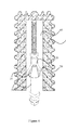
- FIG. 4 where illustrated a hole 60 in the wall 65 , and the anchor 20 of Fig.2 anchored and fixed in said hole.
- fixing petals 24 are spread apart and are under high pressure of the wall 65 from one side, and the distal part 31 of the tubular member 30 from the other side.
- FIG. 5 where illustrated a hole 60 in the wall 65 , and the anchor 20 of Fig.3 anchored and fixed in said hole.
- fixing petals 24 are spread apart and are under high pressure of the wall 65 from one side, and the distal part 31 of the tubular member 30 from the other side.
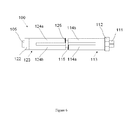
- the anchoring device 100 comprises a screw 105 provided with a head 111 configured for gripping by a user's key (not shown) and a pair of a distal anchor 113 and proximal anchor 123 loosely put on the screw 105.
- the distal anchor 113 is provided with a portion 112 configured for gripping by a user's key (not shown).
- the proximal anchor is provided with a portion 122 which is threadably connected thereto.
- the anchor 113 comprises petal shaped members 114a and 114b.
- the anchor 123 comprises petal shaped members 124a and 124b.
- the petal members 114a and 124a are provided with an outer face 115.
- the petal members 114b and 124b are provided with an internal face 116 (not shown).
- the anchoring device 100 is inserted into the preformed hole (not shown).
- the user rotates the head 111 of the screw 105 by one key (not shown). Concurrently with this action, the user keeps the head 112 fixed by another key (not shown).
- the screw 105 ties the anchors 113 and 123.
- the petal members 114a and 124a having the outer bevel are inserted under the petal members 124b and 114b, respectively.
- the aforesaid petal members 124b and 114b are deployed aside into positions 124c and 114c, respectively (see Fig. 7 ).
- the concept of the current embodiment is similar to previously disclosed but provides more liable fixation in the hole.
- FIGs 8a and 8b depicting interaction of petal members during tying the anchors 113 and 123.
- the internal bevel 116 slides over the outer bevel 115.
- the petal members 114a and 124a are forced to be deployed aside.
- Fig. 9 presenting the anchoring apparatus 100 provided with a collar 130.
- the aforesaid collar is designed to center the anchoring apparatus 100 or similar in the hole 65.
- the main effect achieved by the method described above is that anchor does not rotate in said hole while screw is screwed into the anchor.
- the effect is highly important for proper and stable anchoring of the anchor in the hole.
- the effect is highly useful in cases in which the walls of the hole can be crumbled if an anchor rotates inside the wall during the process anchoring. This undesirable rotation can enlarge the hole, and even damage the hole making it inappropriate for installation of the anchor.
- the anchor of the present invention does not depend on the hole, means the anchor of the present invention does not use the walls of the hole in order not to turn inside the wall during the anchoring. This advantage over the anchors known in the prior art is critical, in many cases, for proper installation of the anchor in the hole.
- the anchor apparatus of the present invention is independent of the size of the hole in which it is anchored. That means that the pre-formed hole can be wider than the diameter of the anchor. During the process of the expansion, the anchor will adapt itself to the size of the hole.
- the present invention comprises two novel elements which can be regarded an inventive step in the field of the invention: (a) The anchor does not rotate during the anchoring process. (b) The size of the hole in which the anchor is going to be installed can be larger than the diameter of the anchor. These two elements do not characterize the anchor of US patent 6,986,623 .
Landscapes
- Engineering & Computer Science (AREA)
- General Engineering & Computer Science (AREA)
- Mining & Mineral Resources (AREA)
- Mechanical Engineering (AREA)
- Structural Engineering (AREA)
- Life Sciences & Earth Sciences (AREA)
- General Life Sciences & Earth Sciences (AREA)
- Geochemistry & Mineralogy (AREA)
- Geology (AREA)
- Joining Of Building Structures In Genera (AREA)
Applications Claiming Priority (1)
| Application Number | Priority Date | Filing Date | Title |
|---|---|---|---|
| US37668410P | 2010-08-25 | 2010-08-25 |
Publications (3)
| Publication Number | Publication Date |
|---|---|
| EP2423432A2 true EP2423432A2 (de) | 2012-02-29 |
| EP2423432A3 EP2423432A3 (de) | 2013-05-15 |
| EP2423432B1 EP2423432B1 (de) | 2014-11-19 |
Family
ID=44672163
Family Applications (1)
| Application Number | Title | Priority Date | Filing Date |
|---|---|---|---|
| EP11167023.8A Not-in-force EP2423432B1 (de) | 2010-08-25 | 2011-05-23 | Verankerungsvorrichtung und Verfahren zu ihrer Verwendung |
Country Status (4)
| Country | Link |
|---|---|
| US (1) | US20120213607A1 (de) |
| EP (1) | EP2423432B1 (de) |
| CA (1) | CA2740943A1 (de) |
| IL (1) | IL213022A (de) |
Cited By (4)
| Publication number | Priority date | Publication date | Assignee | Title |
|---|---|---|---|---|
| CN103133026A (zh) * | 2013-03-26 | 2013-06-05 | 安徽理工大学 | 一种新型胀壳倒楔式可注浆锚杆 |
| CN103774648A (zh) * | 2012-10-26 | 2014-05-07 | 兰州大学 | 一种防止从锚孔中拔出的预应力锚杆 |
| CN104018864A (zh) * | 2014-06-27 | 2014-09-03 | 福州市规划设计研究院 | 超前支护径向锚杆结构及其施工方法 |
| WO2016005901A1 (en) | 2014-07-07 | 2016-01-14 | Defendoor Cc | Fastener |
Families Citing this family (6)
| Publication number | Priority date | Publication date | Assignee | Title |
|---|---|---|---|---|
| CN103774652B (zh) * | 2012-10-26 | 2015-10-28 | 兰州大学 | 顺口防止从锚孔中拔出的预应力锚杆 |
| US9708809B2 (en) * | 2013-03-14 | 2017-07-18 | Darren Bruce Bennett | Anchor and method of using the same |
| AU2019202151A1 (en) * | 2018-08-31 | 2020-03-19 | Jusand Nominees Pty Ltd | Retainer device for a rock anchor, rock anchor system and associated installation method |
| US11732583B2 (en) * | 2018-08-31 | 2023-08-22 | Jusand Nominees Pty Ltd | Retainer device for a rock anchor, rock anchor system and associated installation method |
| USD926025S1 (en) * | 2020-03-03 | 2021-07-27 | Jinsong LI | Bolt |
| USD926561S1 (en) * | 2020-03-17 | 2021-08-03 | Jinsong LI | Bolt |
Citations (1)
| Publication number | Priority date | Publication date | Assignee | Title |
|---|---|---|---|---|
| US6986623B2 (en) | 2003-12-08 | 2006-01-17 | Robertson Jr Roy Lee | Method and apparatus for anchoring a mine roof bolt |
Family Cites Families (1)
| Publication number | Priority date | Publication date | Assignee | Title |
|---|---|---|---|---|
| FR2038851A5 (de) * | 1969-03-31 | 1971-01-08 | Comp Generale Electricite |
-
2011
- 2011-05-19 IL IL213022A patent/IL213022A/en not_active IP Right Cessation
- 2011-05-19 US US13/111,090 patent/US20120213607A1/en not_active Abandoned
- 2011-05-19 CA CA2740943A patent/CA2740943A1/en not_active Abandoned
- 2011-05-23 EP EP11167023.8A patent/EP2423432B1/de not_active Not-in-force
Patent Citations (1)
| Publication number | Priority date | Publication date | Assignee | Title |
|---|---|---|---|---|
| US6986623B2 (en) | 2003-12-08 | 2006-01-17 | Robertson Jr Roy Lee | Method and apparatus for anchoring a mine roof bolt |
Cited By (5)
| Publication number | Priority date | Publication date | Assignee | Title |
|---|---|---|---|---|
| CN103774648A (zh) * | 2012-10-26 | 2014-05-07 | 兰州大学 | 一种防止从锚孔中拔出的预应力锚杆 |
| CN103774648B (zh) * | 2012-10-26 | 2015-12-02 | 兰州大学 | 一种防止从锚孔中拔出的预应力锚杆 |
| CN103133026A (zh) * | 2013-03-26 | 2013-06-05 | 安徽理工大学 | 一种新型胀壳倒楔式可注浆锚杆 |
| CN104018864A (zh) * | 2014-06-27 | 2014-09-03 | 福州市规划设计研究院 | 超前支护径向锚杆结构及其施工方法 |
| WO2016005901A1 (en) | 2014-07-07 | 2016-01-14 | Defendoor Cc | Fastener |
Also Published As
| Publication number | Publication date |
|---|---|
| CA2740943A1 (en) | 2012-02-25 |
| EP2423432B1 (de) | 2014-11-19 |
| IL213022A (en) | 2015-08-31 |
| US20120213607A1 (en) | 2012-08-23 |
| EP2423432A3 (de) | 2013-05-15 |
| IL213022A0 (en) | 2011-07-31 |
Similar Documents
| Publication | Publication Date | Title |
|---|---|---|
| EP2423432B1 (de) | Verankerungsvorrichtung und Verfahren zu ihrer Verwendung | |
| US8499427B2 (en) | Expansion anchor setting apparatus | |
| US8424180B2 (en) | Wedge anchor setting apparatus | |
| TR201812975T4 (tr) | Genişleyen dübel ve genişleyen dübelin montaj yöntemi. | |
| KR101483632B1 (ko) | 단열재용 유니버셜 인서트 | |
| US9551157B2 (en) | Unit fixing insulation to a wall | |
| US20090214315A1 (en) | Drop-in anchor for concrete structures | |
| US4592687A (en) | Roof bolt | |
| US20130185920A1 (en) | Anchor device and method of use | |
| CA2275125A1 (en) | Anchor rod for a connection anchoring system | |
| US3170663A (en) | Screw type earth anchor and pipeline saddle | |
| US20150192016A1 (en) | Truss eye | |
| GB2125872A (en) | Attachment of scaffolding or like structures to buildings | |
| JP6378764B2 (ja) | アンカ装置の設置方法およびかかる方法を実行するための装置 | |
| JP2002001677A (ja) | アンカー抜き取り具 | |
| KR102037167B1 (ko) | 지반고정용 앵커 | |
| JP2007046418A (ja) | 除去式アンカーの定着具及びその定着方法 | |
| GB2087944A (en) | Cavity wall tie | |
| JP4596997B2 (ja) | 壁パネル、そのアンカー及びその取付方法 | |
| CN101660337B (zh) | 自切底锚栓 | |
| US20170073959A1 (en) | Anchoring System & Method of Use | |
| KR20190002896U (ko) | 천장용 세트앵커 | |
| KR102722004B1 (ko) | 개량형 확개타입 앵커구조 | |
| GB1574982A (en) | Cable or pipe clamp | |
| JP5628258B2 (ja) | アンカー撤去工具 |
Legal Events
| Date | Code | Title | Description |
|---|---|---|---|
| AK | Designated contracting states |
Kind code of ref document: A2 Designated state(s): AL AT BE BG CH CY CZ DE DK EE ES FI FR GB GR HR HU IE IS IT LI LT LU LV MC MK MT NL NO PL PT RO RS SE SI SK SM TR |
|
| AX | Request for extension of the european patent |
Extension state: BA ME |
|
| PUAI | Public reference made under article 153(3) epc to a published international application that has entered the european phase |
Free format text: ORIGINAL CODE: 0009012 |
|
| PUAL | Search report despatched |
Free format text: ORIGINAL CODE: 0009013 |
|
| AK | Designated contracting states |
Kind code of ref document: A3 Designated state(s): AL AT BE BG CH CY CZ DE DK EE ES FI FR GB GR HR HU IE IS IT LI LT LU LV MC MK MT NL NO PL PT RO RS SE SI SK SM TR |
|
| AX | Request for extension of the european patent |
Extension state: BA ME |
|
| RIC1 | Information provided on ipc code assigned before grant |
Ipc: F16B 13/08 20060101ALI20130411BHEP Ipc: E21D 21/00 20060101AFI20130411BHEP |
|
| 17P | Request for examination filed |
Effective date: 20131114 |
|
| RBV | Designated contracting states (corrected) |
Designated state(s): AL AT BE BG CH CY CZ DE DK EE ES FI FR GB GR HR HU IE IS IT LI LT LU LV MC MK MT NL NO PL PT RO RS SE SI SK SM TR |
|
| GRAP | Despatch of communication of intention to grant a patent |
Free format text: ORIGINAL CODE: EPIDOSNIGR1 |
|
| INTG | Intention to grant announced |
Effective date: 20140402 |
|
| INTG | Intention to grant announced |
Effective date: 20140409 |
|
| GRAJ | Information related to disapproval of communication of intention to grant by the applicant or resumption of examination proceedings by the epo deleted |
Free format text: ORIGINAL CODE: EPIDOSDIGR1 |
|
| GRAP | Despatch of communication of intention to grant a patent |
Free format text: ORIGINAL CODE: EPIDOSNIGR1 |
|
| INTG | Intention to grant announced |
Effective date: 20140611 |
|
| GRAS | Grant fee paid |
Free format text: ORIGINAL CODE: EPIDOSNIGR3 |
|
| GRAA | (expected) grant |
Free format text: ORIGINAL CODE: 0009210 |
|
| AK | Designated contracting states |
Kind code of ref document: B1 Designated state(s): AL AT BE BG CH CY CZ DE DK EE ES FI FR GB GR HR HU IE IS IT LI LT LU LV MC MK MT NL NO PL PT RO RS SE SI SK SM TR |
|
| REG | Reference to a national code |
Ref country code: GB Ref legal event code: FG4D |
|
| REG | Reference to a national code |
Ref country code: CH Ref legal event code: EP |
|
| REG | Reference to a national code |
Ref country code: AT Ref legal event code: REF Ref document number: 697160 Country of ref document: AT Kind code of ref document: T Effective date: 20141215 |
|
| REG | Reference to a national code |
Ref country code: IE Ref legal event code: FG4D |
|
| REG | Reference to a national code |
Ref country code: DE Ref legal event code: R096 Ref document number: 602011011446 Country of ref document: DE Effective date: 20141231 |
|
| REG | Reference to a national code |
Ref country code: NL Ref legal event code: T3 |
|
| REG | Reference to a national code |
Ref country code: AT Ref legal event code: MK05 Ref document number: 697160 Country of ref document: AT Kind code of ref document: T Effective date: 20141119 |
|
| REG | Reference to a national code |
Ref country code: LT Ref legal event code: MG4D |
|
| PG25 | Lapsed in a contracting state [announced via postgrant information from national office to epo] |
Ref country code: PT Free format text: LAPSE BECAUSE OF FAILURE TO SUBMIT A TRANSLATION OF THE DESCRIPTION OR TO PAY THE FEE WITHIN THE PRESCRIBED TIME-LIMIT Effective date: 20150319 Ref country code: FI Free format text: LAPSE BECAUSE OF FAILURE TO SUBMIT A TRANSLATION OF THE DESCRIPTION OR TO PAY THE FEE WITHIN THE PRESCRIBED TIME-LIMIT Effective date: 20141119 Ref country code: ES Free format text: LAPSE BECAUSE OF FAILURE TO SUBMIT A TRANSLATION OF THE DESCRIPTION OR TO PAY THE FEE WITHIN THE PRESCRIBED TIME-LIMIT Effective date: 20141119 Ref country code: LT Free format text: LAPSE BECAUSE OF FAILURE TO SUBMIT A TRANSLATION OF THE DESCRIPTION OR TO PAY THE FEE WITHIN THE PRESCRIBED TIME-LIMIT Effective date: 20141119 Ref country code: NO Free format text: LAPSE BECAUSE OF FAILURE TO SUBMIT A TRANSLATION OF THE DESCRIPTION OR TO PAY THE FEE WITHIN THE PRESCRIBED TIME-LIMIT Effective date: 20150219 Ref country code: IS Free format text: LAPSE BECAUSE OF FAILURE TO SUBMIT A TRANSLATION OF THE DESCRIPTION OR TO PAY THE FEE WITHIN THE PRESCRIBED TIME-LIMIT Effective date: 20150319 |
|
| PG25 | Lapsed in a contracting state [announced via postgrant information from national office to epo] |
Ref country code: CY Free format text: LAPSE BECAUSE OF FAILURE TO SUBMIT A TRANSLATION OF THE DESCRIPTION OR TO PAY THE FEE WITHIN THE PRESCRIBED TIME-LIMIT Effective date: 20141119 Ref country code: PL Free format text: LAPSE BECAUSE OF FAILURE TO SUBMIT A TRANSLATION OF THE DESCRIPTION OR TO PAY THE FEE WITHIN THE PRESCRIBED TIME-LIMIT Effective date: 20141119 Ref country code: LV Free format text: LAPSE BECAUSE OF FAILURE TO SUBMIT A TRANSLATION OF THE DESCRIPTION OR TO PAY THE FEE WITHIN THE PRESCRIBED TIME-LIMIT Effective date: 20141119 Ref country code: HR Free format text: LAPSE BECAUSE OF FAILURE TO SUBMIT A TRANSLATION OF THE DESCRIPTION OR TO PAY THE FEE WITHIN THE PRESCRIBED TIME-LIMIT Effective date: 20141119 Ref country code: SE Free format text: LAPSE BECAUSE OF FAILURE TO SUBMIT A TRANSLATION OF THE DESCRIPTION OR TO PAY THE FEE WITHIN THE PRESCRIBED TIME-LIMIT Effective date: 20141119 Ref country code: RS Free format text: LAPSE BECAUSE OF FAILURE TO SUBMIT A TRANSLATION OF THE DESCRIPTION OR TO PAY THE FEE WITHIN THE PRESCRIBED TIME-LIMIT Effective date: 20141119 Ref country code: GR Free format text: LAPSE BECAUSE OF FAILURE TO SUBMIT A TRANSLATION OF THE DESCRIPTION OR TO PAY THE FEE WITHIN THE PRESCRIBED TIME-LIMIT Effective date: 20150220 Ref country code: AT Free format text: LAPSE BECAUSE OF FAILURE TO SUBMIT A TRANSLATION OF THE DESCRIPTION OR TO PAY THE FEE WITHIN THE PRESCRIBED TIME-LIMIT Effective date: 20141119 |
|
| PG25 | Lapsed in a contracting state [announced via postgrant information from national office to epo] |
Ref country code: SK Free format text: LAPSE BECAUSE OF FAILURE TO SUBMIT A TRANSLATION OF THE DESCRIPTION OR TO PAY THE FEE WITHIN THE PRESCRIBED TIME-LIMIT Effective date: 20141119 Ref country code: DK Free format text: LAPSE BECAUSE OF FAILURE TO SUBMIT A TRANSLATION OF THE DESCRIPTION OR TO PAY THE FEE WITHIN THE PRESCRIBED TIME-LIMIT Effective date: 20141119 Ref country code: RO Free format text: LAPSE BECAUSE OF FAILURE TO SUBMIT A TRANSLATION OF THE DESCRIPTION OR TO PAY THE FEE WITHIN THE PRESCRIBED TIME-LIMIT Effective date: 20141119 Ref country code: CZ Free format text: LAPSE BECAUSE OF FAILURE TO SUBMIT A TRANSLATION OF THE DESCRIPTION OR TO PAY THE FEE WITHIN THE PRESCRIBED TIME-LIMIT Effective date: 20141119 Ref country code: EE Free format text: LAPSE BECAUSE OF FAILURE TO SUBMIT A TRANSLATION OF THE DESCRIPTION OR TO PAY THE FEE WITHIN THE PRESCRIBED TIME-LIMIT Effective date: 20141119 |
|
| REG | Reference to a national code |
Ref country code: DE Ref legal event code: R097 Ref document number: 602011011446 Country of ref document: DE |
|
| PLBE | No opposition filed within time limit |
Free format text: ORIGINAL CODE: 0009261 |
|
| STAA | Information on the status of an ep patent application or granted ep patent |
Free format text: STATUS: NO OPPOSITION FILED WITHIN TIME LIMIT |
|
| 26N | No opposition filed |
Effective date: 20150820 |
|
| PG25 | Lapsed in a contracting state [announced via postgrant information from national office to epo] |
Ref country code: IT Free format text: LAPSE BECAUSE OF FAILURE TO SUBMIT A TRANSLATION OF THE DESCRIPTION OR TO PAY THE FEE WITHIN THE PRESCRIBED TIME-LIMIT Effective date: 20141119 |
|
| REG | Reference to a national code |
Ref country code: CH Ref legal event code: PL |
|
| PG25 | Lapsed in a contracting state [announced via postgrant information from national office to epo] |
Ref country code: LI Free format text: LAPSE BECAUSE OF NON-PAYMENT OF DUE FEES Effective date: 20150531 Ref country code: MC Free format text: LAPSE BECAUSE OF FAILURE TO SUBMIT A TRANSLATION OF THE DESCRIPTION OR TO PAY THE FEE WITHIN THE PRESCRIBED TIME-LIMIT Effective date: 20141119 Ref country code: LU Free format text: LAPSE BECAUSE OF FAILURE TO SUBMIT A TRANSLATION OF THE DESCRIPTION OR TO PAY THE FEE WITHIN THE PRESCRIBED TIME-LIMIT Effective date: 20150523 Ref country code: CH Free format text: LAPSE BECAUSE OF NON-PAYMENT OF DUE FEES Effective date: 20150531 |
|
| PG25 | Lapsed in a contracting state [announced via postgrant information from national office to epo] |
Ref country code: SI Free format text: LAPSE BECAUSE OF FAILURE TO SUBMIT A TRANSLATION OF THE DESCRIPTION OR TO PAY THE FEE WITHIN THE PRESCRIBED TIME-LIMIT Effective date: 20141119 |
|
| REG | Reference to a national code |
Ref country code: FR Ref legal event code: PLFP Year of fee payment: 6 |
|
| PGFP | Annual fee paid to national office [announced via postgrant information from national office to epo] |
Ref country code: NL Payment date: 20160520 Year of fee payment: 6 |
|
| PGFP | Annual fee paid to national office [announced via postgrant information from national office to epo] |
Ref country code: DE Payment date: 20160520 Year of fee payment: 6 Ref country code: IE Payment date: 20160530 Year of fee payment: 6 Ref country code: GB Payment date: 20160530 Year of fee payment: 6 |
|
| PGFP | Annual fee paid to national office [announced via postgrant information from national office to epo] |
Ref country code: FR Payment date: 20160530 Year of fee payment: 6 |
|
| PG25 | Lapsed in a contracting state [announced via postgrant information from national office to epo] |
Ref country code: MT Free format text: LAPSE BECAUSE OF FAILURE TO SUBMIT A TRANSLATION OF THE DESCRIPTION OR TO PAY THE FEE WITHIN THE PRESCRIBED TIME-LIMIT Effective date: 20141119 |
|
| PG25 | Lapsed in a contracting state [announced via postgrant information from national office to epo] |
Ref country code: SM Free format text: LAPSE BECAUSE OF FAILURE TO SUBMIT A TRANSLATION OF THE DESCRIPTION OR TO PAY THE FEE WITHIN THE PRESCRIBED TIME-LIMIT Effective date: 20141119 Ref country code: BG Free format text: LAPSE BECAUSE OF FAILURE TO SUBMIT A TRANSLATION OF THE DESCRIPTION OR TO PAY THE FEE WITHIN THE PRESCRIBED TIME-LIMIT Effective date: 20141119 Ref country code: HU Free format text: LAPSE BECAUSE OF FAILURE TO SUBMIT A TRANSLATION OF THE DESCRIPTION OR TO PAY THE FEE WITHIN THE PRESCRIBED TIME-LIMIT; INVALID AB INITIO Effective date: 20110523 |
|
| PG25 | Lapsed in a contracting state [announced via postgrant information from national office to epo] |
Ref country code: TR Free format text: LAPSE BECAUSE OF FAILURE TO SUBMIT A TRANSLATION OF THE DESCRIPTION OR TO PAY THE FEE WITHIN THE PRESCRIBED TIME-LIMIT Effective date: 20141119 |
|
| PG25 | Lapsed in a contracting state [announced via postgrant information from national office to epo] |
Ref country code: BE Free format text: LAPSE BECAUSE OF FAILURE TO SUBMIT A TRANSLATION OF THE DESCRIPTION OR TO PAY THE FEE WITHIN THE PRESCRIBED TIME-LIMIT Effective date: 20141119 |
|
| REG | Reference to a national code |
Ref country code: DE Ref legal event code: R119 Ref document number: 602011011446 Country of ref document: DE |
|
| REG | Reference to a national code |
Ref country code: NL Ref legal event code: MM Effective date: 20170601 |
|
| GBPC | Gb: european patent ceased through non-payment of renewal fee |
Effective date: 20170523 |
|
| REG | Reference to a national code |
Ref country code: IE Ref legal event code: MM4A |
|
| REG | Reference to a national code |
Ref country code: FR Ref legal event code: ST Effective date: 20180131 |
|
| PG25 | Lapsed in a contracting state [announced via postgrant information from national office to epo] |
Ref country code: NL Free format text: LAPSE BECAUSE OF NON-PAYMENT OF DUE FEES Effective date: 20170601 |
|
| PG25 | Lapsed in a contracting state [announced via postgrant information from national office to epo] |
Ref country code: DE Free format text: LAPSE BECAUSE OF NON-PAYMENT OF DUE FEES Effective date: 20171201 Ref country code: IE Free format text: LAPSE BECAUSE OF NON-PAYMENT OF DUE FEES Effective date: 20170523 Ref country code: GB Free format text: LAPSE BECAUSE OF NON-PAYMENT OF DUE FEES Effective date: 20170523 |
|
| PG25 | Lapsed in a contracting state [announced via postgrant information from national office to epo] |
Ref country code: FR Free format text: LAPSE BECAUSE OF NON-PAYMENT OF DUE FEES Effective date: 20170531 |
|
| PG25 | Lapsed in a contracting state [announced via postgrant information from national office to epo] |
Ref country code: MK Free format text: LAPSE BECAUSE OF FAILURE TO SUBMIT A TRANSLATION OF THE DESCRIPTION OR TO PAY THE FEE WITHIN THE PRESCRIBED TIME-LIMIT Effective date: 20141119 |
|
| PG25 | Lapsed in a contracting state [announced via postgrant information from national office to epo] |
Ref country code: AL Free format text: LAPSE BECAUSE OF FAILURE TO SUBMIT A TRANSLATION OF THE DESCRIPTION OR TO PAY THE FEE WITHIN THE PRESCRIBED TIME-LIMIT Effective date: 20141119 |