EP2423436A2 - Forme de profil d'aube pour compresseur - Google Patents
Forme de profil d'aube pour compresseur Download PDFInfo
- Publication number
- EP2423436A2 EP2423436A2 EP11178245A EP11178245A EP2423436A2 EP 2423436 A2 EP2423436 A2 EP 2423436A2 EP 11178245 A EP11178245 A EP 11178245A EP 11178245 A EP11178245 A EP 11178245A EP 2423436 A2 EP2423436 A2 EP 2423436A2
- Authority
- EP
- European Patent Office
- Prior art keywords
- rotor
- blade
- rotor blade
- blade height
- blades
- Prior art date
- Legal status (The legal status is an assumption and is not a legal conclusion. Google has not performed a legal analysis and makes no representation as to the accuracy of the status listed.)
- Granted
Links
Images


Classifications
-
- F—MECHANICAL ENGINEERING; LIGHTING; HEATING; WEAPONS; BLASTING
- F01—MACHINES OR ENGINES IN GENERAL; ENGINE PLANTS IN GENERAL; STEAM ENGINES
- F01D—NON-POSITIVE DISPLACEMENT MACHINES OR ENGINES, e.g. STEAM TURBINES
- F01D5/00—Blades; Blade-carrying members; Heating, heat-insulating, cooling or antivibration means on the blades or the members
- F01D5/12—Blades
- F01D5/14—Form or construction
- F01D5/141—Shape, i.e. outer, aerodynamic form
-
- F—MECHANICAL ENGINEERING; LIGHTING; HEATING; WEAPONS; BLASTING
- F02—COMBUSTION ENGINES; HOT-GAS OR COMBUSTION-PRODUCT ENGINE PLANTS
- F02C—GAS-TURBINE PLANTS; AIR INTAKES FOR JET-PROPULSION PLANTS; CONTROLLING FUEL SUPPLY IN AIR-BREATHING JET-PROPULSION PLANTS
- F02C3/00—Gas-turbine plants characterised by the use of combustion products as the working fluid
- F02C3/04—Gas-turbine plants characterised by the use of combustion products as the working fluid having a turbine driving a compressor
- F02C3/06—Gas-turbine plants characterised by the use of combustion products as the working fluid having a turbine driving a compressor the compressor comprising only axial stages
-
- F—MECHANICAL ENGINEERING; LIGHTING; HEATING; WEAPONS; BLASTING
- F02—COMBUSTION ENGINES; HOT-GAS OR COMBUSTION-PRODUCT ENGINE PLANTS
- F02C—GAS-TURBINE PLANTS; AIR INTAKES FOR JET-PROPULSION PLANTS; CONTROLLING FUEL SUPPLY IN AIR-BREATHING JET-PROPULSION PLANTS
- F02C7/00—Features, components parts, details or accessories, not provided for in, or of interest apart form groups F02C1/00 - F02C6/00; Air intakes for jet-propulsion plants
-
- F—MECHANICAL ENGINEERING; LIGHTING; HEATING; WEAPONS; BLASTING
- F04—POSITIVE - DISPLACEMENT MACHINES FOR LIQUIDS; PUMPS FOR LIQUIDS OR ELASTIC FLUIDS
- F04D—NON-POSITIVE-DISPLACEMENT PUMPS
- F04D29/00—Details, component parts, or accessories
- F04D29/26—Rotors specially for elastic fluids
- F04D29/32—Rotors specially for elastic fluids for axial flow pumps
- F04D29/321—Rotors specially for elastic fluids for axial flow pumps for axial flow compressors
- F04D29/324—Blades
-
- F—MECHANICAL ENGINEERING; LIGHTING; HEATING; WEAPONS; BLASTING
- F04—POSITIVE - DISPLACEMENT MACHINES FOR LIQUIDS; PUMPS FOR LIQUIDS OR ELASTIC FLUIDS
- F04D—NON-POSITIVE-DISPLACEMENT PUMPS
- F04D29/00—Details, component parts, or accessories
- F04D29/26—Rotors specially for elastic fluids
- F04D29/32—Rotors specially for elastic fluids for axial flow pumps
- F04D29/38—Blades
-
- F—MECHANICAL ENGINEERING; LIGHTING; HEATING; WEAPONS; BLASTING
- F05—INDEXING SCHEMES RELATING TO ENGINES OR PUMPS IN VARIOUS SUBCLASSES OF CLASSES F01-F04
- F05D—INDEXING SCHEME FOR ASPECTS RELATING TO NON-POSITIVE-DISPLACEMENT MACHINES OR ENGINES, GAS-TURBINES OR JET-PROPULSION PLANTS
- F05D2250/00—Geometry
- F05D2250/70—Shape
- F05D2250/74—Shape given by a set or table of xyz-coordinates
-
- F—MECHANICAL ENGINEERING; LIGHTING; HEATING; WEAPONS; BLASTING
- F05—INDEXING SCHEMES RELATING TO ENGINES OR PUMPS IN VARIOUS SUBCLASSES OF CLASSES F01-F04
- F05D—INDEXING SCHEME FOR ASPECTS RELATING TO NON-POSITIVE-DISPLACEMENT MACHINES OR ENGINES, GAS-TURBINES OR JET-PROPULSION PLANTS
- F05D2260/00—Function
- F05D2260/96—Preventing, counteracting or reducing vibration or noise
-
- Y—GENERAL TAGGING OF NEW TECHNOLOGICAL DEVELOPMENTS; GENERAL TAGGING OF CROSS-SECTIONAL TECHNOLOGIES SPANNING OVER SEVERAL SECTIONS OF THE IPC; TECHNICAL SUBJECTS COVERED BY FORMER USPC CROSS-REFERENCE ART COLLECTIONS [XRACs] AND DIGESTS
- Y10—TECHNICAL SUBJECTS COVERED BY FORMER USPC
- Y10S—TECHNICAL SUBJECTS COVERED BY FORMER USPC CROSS-REFERENCE ART COLLECTIONS [XRACs] AND DIGESTS
- Y10S416/00—Fluid reaction surfaces, i.e. impellers
- Y10S416/02—Formulas of curves
Definitions
- the present invention relates generally to airfoils and, more specifically, to airfoil shapes used in compressors, e.g., as part of gas turbines.
- a compressor is a machine which accelerates gas particles to, ultimately, increase the pressure of a compressible fluid, e.g., a gas, through the use of mechanical energy.
- Compressors are used in a number of different applications, including operating as an initial stage of a gas turbine engine.
- centrifugal compressors in which mechanical energy operates on gas input to the compressor by way of centrifugal acceleration, e.g., by rotating a centrifugal impeller (sometimes also called a "rotor") by which the compressible fluid is passing, and axial compressors which have, as each stage, a drum having a number of annular airfoil rows (blades) attached thereto.
- axial and centrifugal compressors can be said to be part of a class of machinery known as “turbo machines” or “turbo rotating machines”.
- a blade of a compressor stator should achieve thermal and mechanical operating requirements associated with the particular stage in which it is located.
- a blade of a compressor rotor should also achieve thermal and mechanical operating requirements associated with the particular stage of the gas turbine in which it is located.
- Blades e.g., as part of a rotor or a stator associated with a turbo machine, with particular shapes to optimize operating characteristics.
- blade thickness as a function of blade height can be tailored to operating characteristics of the turbo machine.
- a rotor blade having a nominal surface profile substantially in accordance with Cartesian coordinates X, Y and Z as set forth in TABLE 1, and wherein X and Y are distances in millimeters which, when connected by smooth, continuing arcs, define airfoil profile sections at each distance Z in millimeters, the airfoil profile sections at the Z distances being joined smoothly with one another to form a complete airfoil shape.
- a rotor blade includes a platform, a root portion of the rotor blade connected to the platform, and a blade surface ending in a tip portion, the blade surface having a cross-sectional airfoil shape, wherein a thickness of the rotor blade varies as a function of rotor blade height in accordance with three different linear functions.
- a turbo machine includes a drive shaft, at least one rotor wheel, a plurality of circumferentially spaced rotor blades mounted on the rotor wheel, a stator, and a plurality of circumferentially spaced stator blades attached to the stator wherein at least one of the plurality of rotor blades and plurality of stator blades further includes: a platform, a root portion of the at least one of the plurality of rotor blades and plurality of stator blades connected to the platform, and a blade surface ending in a tip portion, the blade surface having a cross-sectional airfoil shape,wherein a thickness of the at least one of the plurality of rotor blades and plurality of stator blades varies as a function of blade height in accordance with three different linear functions.
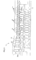
- Figures 1 depicts an exemplary axial compressor in which blade shapes according to exemplary embodiments can be implemented
- Figures 2 shows a suction side of a rotor blade according to an exemplary embodiment
- Figure 3 shows a pressure side of a rotor blade according to an exemplary embodiment
- Figure 4 illustrates aspects associated with a coordinate system used to define a loci of points according to an exemplary embodiment
- Figure 5 is a graph depicting blade thickness as a function of blade height according to an exemplary embodiment.
- rotor blades impart kinetic energy to the air flow and therefore bring about a desired pressure rise across the compressor.
- stator airfoils Directly following the rotor airfoils is a stage of stator airfoils. Both the rotor and stator airfoils turn the airflow, slow the airflow velocity (in the respective airfoil frame of reference), and yield a rise in the static pressure of the airflow.
- the configuration of the airfoils determines stage airflow efficiency, aeromechanics, smooth laminar flow from stage to stage, reduced thermal stresses, enhanced interrelation of the stages to effectively pass the airflow from stage to stage, and reduced mechanical stresses, among other desirable aspects of these exemplary embodiments.
- multiple rows of rotor/stator stages are stacked in axial flow compressors to achieve a desired discharge to inlet pressure ratio.
- Rotor and stator airfoils can be secured to rotor wheels or stator case by an appropriate attachment configuration, often known as a "root”, “base” or “dovetail”, examples of which are described below.
- Figure 1 illustrates an exemplary axial compressor 100, e.g., associated with a gas turbine compressor.
- an axial compressor typically includes a plurality of compressor stages, for example seventeen or eighteen stages, however those skilled in the art will appreciate that axial compressors according to exemplary embodiments may include any number of rotor stages and stator stages.
- the stage 100 of the axial compressor illustrated in Figure 1 includes a plurality of circumferentially spaced rotor blades 102 mounted on a rotor wheel or drum 104 and a plurality of circumferentially spaced stator blades 106 attached to a static compressor case 108.
- Each of the rotor wheels 104 is attached to aft drive shaft 110, which is connected to the turbine section (not shown) of the engine.
- the rotor blades 102 and stator blades 106 are disposed in the flow path of the axial compressor.
- the direction of airflow along the flow path, in this exemplary axial compressor, is indicated by the arrow 112. It will be appreciated that this stage 100 of an axial compressor is merely exemplary of the various stages of an axial compressor and that the illustrated and described stage 100 of the axial compressor is not intended to limit the invention in any manner.
- Rotor blades 102 are illustrated in more detail in Figures 2 and 3 which show opposite sides of a rotor blade 102.
- such rotor blades 102 according to these exemplary embodiments can be used in the first stage of axial compressors like that shown in Figure 1 , i.e., in the stage closest to the inlet associated with the process flow.
- Figure 2 depicts the suction side of a rotor blade 102 according to an exemplary embodiment
- Figure 3 depicts the pressure side of the same rotor blade 102 having a leading edge (LE) and trailing edge (TE) as shown relative to the compressor flow path 112.
- LE leading edge
- TE trailing edge
- Each rotor blade 102 can, for example, be provided with a platform 200, and a substantially axial (or near axial) entry dovetail 202 for connection with a complementary-shaped mating dovetail (not shown) on the rotor wheel 104. Additionally, each rotor blade 102 includes a rotor blade airfoil 204 having a profile at any cross-section thereof, i.e., from the airfoil root 206 to the rotor blade tip 208 in the general shape of an airfoil, as will be discussed in more detail below.
- a set or loci of points in space are provided in Table 1 below. It can be seen that the exemplary rotor blade 102 in Figures 2 and 3 have sixteen section lines, although those skilled in the art will recognize that any number of sections could be defined.
- This set or loci of points is intended to meet the section requirements associated with the section or sections in which rotor blades 102 are to be used so that the section can be manufactured.
- This loci of points is also intended to meet the desired specifications for stage efficiency and reduced thermal and mechanical stresses. The loci of points are arrived at by simulations, iterating between aerodynamic and mechanical loadings and enabling compressors designed in accordance with exemplary embodiments to run in an efficient, safe and smooth manner.
- the loci defines the rotor blade airfoil profile according to exemplary embodiments and can include a set of points which are defined relative to an axis of rotation of the engine.
- a Cartesian coordinate system of X, Y and Z values can be defined and used to reference the points in the loci.
- the Cartesian coordinate system has orthogonally-related X, Y and Z axes.
- the X axis lies parallel to the engine's centerline, as illustrated in Figure 4 .
- a positive X coordinate value is thus axial toward the aft, for example toward the exhaust end of the axial compressor.
- a positive Y coordinate value is directed circumferentially following engine counterclockwise direction of rotation.
- a positive Z coordinate value is directed radially outward toward tip of the airfoil 204, i.e., in the direction towards the static casing 108 of the compressor.
- a Point-0 passing through the intersection of the airfoil 204 and the platform 200 along the stacking axis, as illustrated in Figure 4 .
- the Point-0 is defined as the reference section where the Z coordinate of the Table 1 below is at 416.97 millimeters, which is a set predetermined distance from the engine or rotor centerline.
- the Table 1 of points which define the rotor blade 102's surface is provided below.
- the thickness of the rotor blade 102 changes continuously along the blade height in order to, for example, move a resonance frequency associated with movement of the rotor blade 102 to, for example, improve a design margin associated with fatigue. This change in thickness can be seen, for example, in the plot of Figure 5 .
- Tmax - 1.0209 * h + 1.2058 where h is blade height percentage
- function 500 depicts rotor blade thickness as a function of blade height for an exemplary embodiment
- function 502 depicts the same quantity for a baseline design
- exemplary embodiments provide for a thicker rotor blade through about the first 75% of the blade height (where the functions cross) and then for a thinner rotor blade relative to the baseline design.
- Table 1 provides sufficient data to completely define the shape of an airfoil 204 according to exemplary embodiments.
- the profile section of the rotor blade airfoil 204 at each Z distance along the length of the airfoil can be ascertained.
- each profile section of the airfoil 204 at each distance Z can be fixed.
- the airfoil profiles of the various surface locations between the distances Z are determined by smoothly connecting the adjacent profile sections to one another, thus forming the airfoil 204's profile.
- the values set forth above in Table 1 represent the airfoil profiles according to exemplary embodiments at ambient, non-operating or non-hot conditions and are for an uncoated airfoil.
- Table 1 The table values provided in Table 1 are generated and shown to two decimal places for determining the profile of the airfoil 204. There are typical manufacturing tolerances as well as coatings, which should be accounted for in the actual profile of the airfoil. Accordingly, it will be appreciated by those skilled in the art that the values for the profile given in Table 1 are for a nominal airfoil 204. It will therefore be appreciated that the actual values encompassed by these exemplary embodiments are not limited to the precise values shown in Table 1, but are instead intended to include a range of values around those specified in the table.
- a distance of about +/- 1.0mm in a direction normal to any surface location along the airfoil profile defines an airfoil profile envelope for a rotor blade airfoil design and compressor according to these exemplary embodiments.
- a distance of about +/- 1.0mm, and preferably about +/- 0.5 mm, in a direction normal to any surface location along the airfoil profile defines a range of variation between measured points on the actual airfoil surface at nominal cold or room temperature and the ideal position of those points, at the same temperature, according to exemplary embodiments.
- the shape of the airfoils 204 will also vary from their cold or room temperature manufactured shape, to their heated shape when placed into operation in a gas turbine engine. As the airfoils 204 heat up in service, stress and temperature will cause a change in the X, Y, Z values of the cold or room temperature points depicted in Table 1. Thus exemplary embodiments further contemplate the inclusion of variances associated with heating of the airfoils 204 during normal operation.
- the airfoil as embodied by the exemplary embodiments, can find application as a first stage rotor shape.
- the coordinate values for the X, Y and Z coordinates are set forth in millimeters, although other units of dimensions may be used when the values are appropriately converted. These values exclude fillet regions of the platform.
Landscapes
- Engineering & Computer Science (AREA)
- Mechanical Engineering (AREA)
- General Engineering & Computer Science (AREA)
- Chemical & Material Sciences (AREA)
- Combustion & Propulsion (AREA)
- Physics & Mathematics (AREA)
- Fluid Mechanics (AREA)
- Structures Of Non-Positive Displacement Pumps (AREA)
- Organic Low-Molecular-Weight Compounds And Preparation Thereof (AREA)
- Steroid Compounds (AREA)
Applications Claiming Priority (1)
| Application Number | Priority Date | Filing Date | Title |
|---|---|---|---|
| ITCO2010A000045A IT1401661B1 (it) | 2010-08-25 | 2010-08-25 | Forma di profilo areodinamico per compressore. |
Publications (3)
| Publication Number | Publication Date |
|---|---|
| EP2423436A2 true EP2423436A2 (fr) | 2012-02-29 |
| EP2423436A3 EP2423436A3 (fr) | 2014-06-11 |
| EP2423436B1 EP2423436B1 (fr) | 2016-06-01 |
Family
ID=43735310
Family Applications (1)
| Application Number | Title | Priority Date | Filing Date |
|---|---|---|---|
| EP11178245.4A Not-in-force EP2423436B1 (fr) | 2010-08-25 | 2011-08-22 | Forme de profil d'aube pour compresseur |
Country Status (8)
| Country | Link |
|---|---|
| US (1) | US8882456B2 (fr) |
| EP (1) | EP2423436B1 (fr) |
| JP (1) | JP6055172B2 (fr) |
| KR (1) | KR101819240B1 (fr) |
| CN (1) | CN102384103B (fr) |
| CA (1) | CA2749488A1 (fr) |
| IT (1) | IT1401661B1 (fr) |
| RU (1) | RU2581501C2 (fr) |
Cited By (6)
| Publication number | Priority date | Publication date | Assignee | Title |
|---|---|---|---|---|
| FR3005682A1 (fr) * | 2013-05-14 | 2014-11-21 | Man Diesel & Turbo Se | Aube de compresseur axial ainsi que compresseur equipe de telles aubes |
| EP3026214A1 (fr) * | 2014-11-25 | 2016-06-01 | Pratt & Whitney Canada Corp. | Profil aérodynamique avec distribution d'épaisseur étagée dans le sens radial |
| US10473112B2 (en) | 2017-02-14 | 2019-11-12 | Rolls-Royce Plc | Gas turbine engine fan blade |
| US10577937B2 (en) | 2017-02-14 | 2020-03-03 | Rolls-Royce Plc | Gas turbine engine fan blade |
| EP4083384A1 (fr) * | 2021-04-30 | 2022-11-02 | General Electric Company | Profil aérodynamique d'aube rotorique de compresseur |
| EP4083383A1 (fr) * | 2021-04-30 | 2022-11-02 | General Electric Company | Profil aérodynamique d'aube rotorique de compresseur |
Families Citing this family (17)
| Publication number | Priority date | Publication date | Assignee | Title |
|---|---|---|---|---|
| US9297259B2 (en) * | 2012-06-14 | 2016-03-29 | Alstom Technology | Compressor blade |
| US8926287B2 (en) * | 2012-06-19 | 2015-01-06 | General Electric Company | Airfoil shape for a compressor |
| US8961119B2 (en) * | 2012-06-19 | 2015-02-24 | General Electric Company | Airfoil shape for a compressor |
| US10385698B2 (en) * | 2016-07-13 | 2019-08-20 | Safran Aircraft Engines | Optimized aerodynamic profile for a turbine vane, in particular for a nozzle of the sixth stage of a turbine |
| US10385697B2 (en) * | 2016-07-13 | 2019-08-20 | Safran Aircraft Engines | Optimized aerodynamic profile for a turbine blade, in particular for a rotary wheel of the fourth stage of a turbine |
| US10458245B2 (en) * | 2016-07-13 | 2019-10-29 | Safran Aircraft Engines | Optimized aerodynamic profile for a turbine blade, in particular for a rotary wheel of the third stage of a turbine |
| US10287886B2 (en) * | 2016-09-22 | 2019-05-14 | General Electric Company | Airfoil shape for first stage compressor rotor blade |
| US10087952B2 (en) * | 2016-09-23 | 2018-10-02 | General Electric Company | Airfoil shape for first stage compressor stator vane |
| US10436034B2 (en) * | 2017-05-15 | 2019-10-08 | General Electric Company | Airfoil shape for a turbine rotor blade |
| CN107829985B (zh) * | 2017-09-28 | 2019-09-10 | 中国航发动力股份有限公司 | 一种航空发动机风扇叶片固有频率的修正方法 |
| GB201813666D0 (en) * | 2018-08-22 | 2018-10-03 | Rolls Royce Plc | Fan blade |
| US11421702B2 (en) * | 2019-08-21 | 2022-08-23 | Pratt & Whitney Canada Corp. | Impeller with chordwise vane thickness variation |
| US20210381385A1 (en) * | 2020-06-03 | 2021-12-09 | Honeywell International Inc. | Characteristic distribution for rotor blade of booster rotor |
| US11306594B1 (en) * | 2021-02-25 | 2022-04-19 | Doosan Heavy Industries & Construction Co., Ltd. | Airfoil profile |
| US11255195B1 (en) * | 2021-02-25 | 2022-02-22 | Doosan Heavy Industries & Construction Co., Ltd. | Airfoil profile |
| US11428159B1 (en) * | 2021-07-01 | 2022-08-30 | Doosan Enerbility Co., Ltd. | Airfoil profile for a turbine blade |
| US11480056B1 (en) * | 2021-07-01 | 2022-10-25 | Doosan Heavy Industries & Construction Co., Ltd. | Airfoil profile for a turbine blade |
Family Cites Families (15)
| Publication number | Priority date | Publication date | Assignee | Title |
|---|---|---|---|---|
| FR2536365A1 (fr) * | 1982-11-18 | 1984-05-25 | Onera (Off Nat Aerospatiale) | Pale pour propulseur d'aeronef |
| US5980209A (en) | 1997-06-27 | 1999-11-09 | General Electric Co. | Turbine blade with enhanced cooling and profile optimization |
| EP0894558A1 (fr) * | 1997-07-29 | 1999-02-03 | Siemens Aktiengesellschaft | Aube de turbine et procédé de fabrication d'un aube de turbine |
| US6761535B1 (en) * | 2003-04-28 | 2004-07-13 | General Electric Company | Internal core profile for a turbine bucket |
| ITBO20040417A1 (it) * | 2004-07-06 | 2004-10-06 | Spal Srl | Ventola a flusso assiale |
| ITMI20041804A1 (it) * | 2004-09-21 | 2004-12-21 | Nuovo Pignone Spa | Pala di un rutore di un primo stadio di una turbina a gas |
| US7497664B2 (en) * | 2005-08-16 | 2009-03-03 | General Electric Company | Methods and apparatus for reducing vibrations induced to airfoils |
| FR2891594A1 (fr) * | 2005-09-30 | 2007-04-06 | Snecma Sa | Aube de compresseur a sommet chanfreine |
| ITMI20060341A1 (it) * | 2006-02-27 | 2007-08-28 | Nuovo Pignone Spa | Pala di un rotore di un non stadio di un compressore |
| ITMI20060340A1 (it) | 2006-02-27 | 2007-08-28 | Nuovo Pignone Spa | Pala di un rotore di un secondo stadio di un compressore |
| US7572105B2 (en) * | 2006-10-25 | 2009-08-11 | General Electric Company | Airfoil shape for a compressor |
| US8057188B2 (en) * | 2008-05-21 | 2011-11-15 | Alstom Technologies Ltd. Llc | Compressor airfoil |
| US8038411B2 (en) | 2008-07-14 | 2011-10-18 | Pratt & Whitney Canada Corp. | Compressor turbine blade airfoil profile |
| FR2935016A1 (fr) * | 2008-08-13 | 2010-02-19 | Snecma | Profil aerodynamique optimise pour une aube de turbine |
| US8573945B2 (en) * | 2009-11-13 | 2013-11-05 | Alstom Technology Ltd. | Compressor stator vane |
-
2010
- 2010-08-25 IT ITCO2010A000045A patent/IT1401661B1/it active
-
2011
- 2011-08-18 CA CA2749488A patent/CA2749488A1/fr not_active Abandoned
- 2011-08-22 EP EP11178245.4A patent/EP2423436B1/fr not_active Not-in-force
- 2011-08-23 JP JP2011181101A patent/JP6055172B2/ja not_active Expired - Fee Related
- 2011-08-24 KR KR1020110084430A patent/KR101819240B1/ko not_active Expired - Fee Related
- 2011-08-24 RU RU2011135181/06A patent/RU2581501C2/ru not_active IP Right Cessation
- 2011-08-25 CN CN201110257320.1A patent/CN102384103B/zh not_active Expired - Fee Related
- 2011-08-25 US US13/218,106 patent/US8882456B2/en active Active
Non-Patent Citations (1)
| Title |
|---|
| None |
Cited By (8)
| Publication number | Priority date | Publication date | Assignee | Title |
|---|---|---|---|---|
| FR3005682A1 (fr) * | 2013-05-14 | 2014-11-21 | Man Diesel & Turbo Se | Aube de compresseur axial ainsi que compresseur equipe de telles aubes |
| EP3026214A1 (fr) * | 2014-11-25 | 2016-06-01 | Pratt & Whitney Canada Corp. | Profil aérodynamique avec distribution d'épaisseur étagée dans le sens radial |
| US9845684B2 (en) | 2014-11-25 | 2017-12-19 | Pratt & Whitney Canada Corp. | Airfoil with stepped spanwise thickness distribution |
| US10718215B2 (en) | 2014-11-25 | 2020-07-21 | Pratt & Whitney Canada Corp. | Airfoil with stepped spanwise thickness distribution |
| US10473112B2 (en) | 2017-02-14 | 2019-11-12 | Rolls-Royce Plc | Gas turbine engine fan blade |
| US10577937B2 (en) | 2017-02-14 | 2020-03-03 | Rolls-Royce Plc | Gas turbine engine fan blade |
| EP4083384A1 (fr) * | 2021-04-30 | 2022-11-02 | General Electric Company | Profil aérodynamique d'aube rotorique de compresseur |
| EP4083383A1 (fr) * | 2021-04-30 | 2022-11-02 | General Electric Company | Profil aérodynamique d'aube rotorique de compresseur |
Also Published As
| Publication number | Publication date |
|---|---|
| RU2581501C2 (ru) | 2016-04-20 |
| KR20120019399A (ko) | 2012-03-06 |
| ITCO20100045A1 (it) | 2012-02-26 |
| IT1401661B1 (it) | 2013-08-02 |
| CN102384103B (zh) | 2015-12-16 |
| JP6055172B2 (ja) | 2016-12-27 |
| US20120051901A1 (en) | 2012-03-01 |
| EP2423436B1 (fr) | 2016-06-01 |
| RU2011135181A (ru) | 2013-02-27 |
| CN102384103A (zh) | 2012-03-21 |
| KR101819240B1 (ko) | 2018-01-16 |
| US8882456B2 (en) | 2014-11-11 |
| JP2012047175A (ja) | 2012-03-08 |
| EP2423436A3 (fr) | 2014-06-11 |
| CA2749488A1 (fr) | 2012-02-25 |
Similar Documents
| Publication | Publication Date | Title |
|---|---|---|
| EP2423436B1 (fr) | Forme de profil d'aube pour compresseur | |
| US7517196B2 (en) | Airfoil shape for a compressor | |
| EP1918516A2 (fr) | Forme de surface portante pour compresseur | |
| EP1921261A2 (fr) | Forme de surface portable pour compresseur | |
| US7497665B2 (en) | Airfoil shape for a compressor | |
| US7534092B2 (en) | Airfoil shape for a compressor | |
| US7566202B2 (en) | Airfoil shape for a compressor | |
| EP1921264A2 (fr) | Forme de profil aérodynamique pour un compresseur | |
| EP1921266A2 (fr) | Forme de profil aérodynamique pour un compresseur | |
| EP1921265A2 (fr) | Forme de profil aérodynamique pour un compresseur | |
| US7534094B2 (en) | Airfoil shape for a compressor | |
| US7513749B2 (en) | Airfoil shape for a compressor | |
| US7517188B2 (en) | Airfoil shape for a compressor | |
| EP1921262A2 (fr) | Forme de surface portable pour compresseur | |
| EP1918518A2 (fr) | Forme de surface portante pour compresseur | |
| EP1970534A2 (fr) | Profil aérodynamique pour un compresseur | |
| EP1921267A2 (fr) | Forme de profil aérodynamique pour un compresseur | |
| EP1916387A2 (fr) | Profil aérodynamique pour un compresseur | |
| EP1916384A2 (fr) | Profil aérodynamique pour un compresseur | |
| EP1921257A2 (fr) | Forme de surface portable pour compresseur | |
| EP1916383A2 (fr) | Profil aérodynamique pour compresseur | |
| EP1918514A2 (fr) | Forme de surface portante pour compresseur | |
| EP1918519A2 (fr) | Forme de surface portable pour compresseur | |
| US20180017070A1 (en) | Compressor blade for a gas turbine engine |
Legal Events
| Date | Code | Title | Description |
|---|---|---|---|
| AK | Designated contracting states |
Kind code of ref document: A2 Designated state(s): AL AT BE BG CH CY CZ DE DK EE ES FI FR GB GR HR HU IE IS IT LI LT LU LV MC MK MT NL NO PL PT RO RS SE SI SK SM TR |
|
| AX | Request for extension of the european patent |
Extension state: BA ME |
|
| PUAI | Public reference made under article 153(3) epc to a published international application that has entered the european phase |
Free format text: ORIGINAL CODE: 0009012 |
|
| PUAL | Search report despatched |
Free format text: ORIGINAL CODE: 0009013 |
|
| AK | Designated contracting states |
Kind code of ref document: A3 Designated state(s): AL AT BE BG CH CY CZ DE DK EE ES FI FR GB GR HR HU IE IS IT LI LT LU LV MC MK MT NL NO PL PT RO RS SE SI SK SM TR |
|
| AX | Request for extension of the european patent |
Extension state: BA ME |
|
| RIC1 | Information provided on ipc code assigned before grant |
Ipc: F04D 29/32 20060101ALI20140507BHEP Ipc: F01D 5/14 20060101AFI20140507BHEP |
|
| 17P | Request for examination filed |
Effective date: 20141211 |
|
| RBV | Designated contracting states (corrected) |
Designated state(s): AL AT BE BG CH CY CZ DE DK EE ES FI FR GB GR HR HU IE IS IT LI LT LU LV MC MK MT NL NO PL PT RO RS SE SI SK SM TR |
|
| 17Q | First examination report despatched |
Effective date: 20150122 |
|
| GRAP | Despatch of communication of intention to grant a patent |
Free format text: ORIGINAL CODE: EPIDOSNIGR1 |
|
| INTG | Intention to grant announced |
Effective date: 20151130 |
|
| INTG | Intention to grant announced |
Effective date: 20160105 |
|
| GRAS | Grant fee paid |
Free format text: ORIGINAL CODE: EPIDOSNIGR3 |
|
| GRAA | (expected) grant |
Free format text: ORIGINAL CODE: 0009210 |
|
| AK | Designated contracting states |
Kind code of ref document: B1 Designated state(s): AL AT BE BG CH CY CZ DE DK EE ES FI FR GB GR HR HU IE IS IT LI LT LU LV MC MK MT NL NO PL PT RO RS SE SI SK SM TR |
|
| REG | Reference to a national code |
Ref country code: GB Ref legal event code: FG4D |
|
| REG | Reference to a national code |
Ref country code: CH Ref legal event code: EP Ref country code: AT Ref legal event code: REF Ref document number: 804000 Country of ref document: AT Kind code of ref document: T Effective date: 20160615 |
|
| REG | Reference to a national code |
Ref country code: IE Ref legal event code: FG4D |
|
| REG | Reference to a national code |
Ref country code: DE Ref legal event code: R096 Ref document number: 602011027056 Country of ref document: DE |
|
| REG | Reference to a national code |
Ref country code: FR Ref legal event code: PLFP Year of fee payment: 6 |
|
| REG | Reference to a national code |
Ref country code: LT Ref legal event code: MG4D |
|
| REG | Reference to a national code |
Ref country code: NL Ref legal event code: MP Effective date: 20160601 |
|
| PG25 | Lapsed in a contracting state [announced via postgrant information from national office to epo] |
Ref country code: FI Free format text: LAPSE BECAUSE OF FAILURE TO SUBMIT A TRANSLATION OF THE DESCRIPTION OR TO PAY THE FEE WITHIN THE PRESCRIBED TIME-LIMIT Effective date: 20160601 Ref country code: NO Free format text: LAPSE BECAUSE OF FAILURE TO SUBMIT A TRANSLATION OF THE DESCRIPTION OR TO PAY THE FEE WITHIN THE PRESCRIBED TIME-LIMIT Effective date: 20160901 Ref country code: LT Free format text: LAPSE BECAUSE OF FAILURE TO SUBMIT A TRANSLATION OF THE DESCRIPTION OR TO PAY THE FEE WITHIN THE PRESCRIBED TIME-LIMIT Effective date: 20160601 |
|
| REG | Reference to a national code |
Ref country code: AT Ref legal event code: MK05 Ref document number: 804000 Country of ref document: AT Kind code of ref document: T Effective date: 20160601 |
|
| PG25 | Lapsed in a contracting state [announced via postgrant information from national office to epo] |
Ref country code: NL Free format text: LAPSE BECAUSE OF FAILURE TO SUBMIT A TRANSLATION OF THE DESCRIPTION OR TO PAY THE FEE WITHIN THE PRESCRIBED TIME-LIMIT Effective date: 20160601 Ref country code: SE Free format text: LAPSE BECAUSE OF FAILURE TO SUBMIT A TRANSLATION OF THE DESCRIPTION OR TO PAY THE FEE WITHIN THE PRESCRIBED TIME-LIMIT Effective date: 20160601 Ref country code: LV Free format text: LAPSE BECAUSE OF FAILURE TO SUBMIT A TRANSLATION OF THE DESCRIPTION OR TO PAY THE FEE WITHIN THE PRESCRIBED TIME-LIMIT Effective date: 20160601 Ref country code: ES Free format text: LAPSE BECAUSE OF FAILURE TO SUBMIT A TRANSLATION OF THE DESCRIPTION OR TO PAY THE FEE WITHIN THE PRESCRIBED TIME-LIMIT Effective date: 20160601 Ref country code: RS Free format text: LAPSE BECAUSE OF FAILURE TO SUBMIT A TRANSLATION OF THE DESCRIPTION OR TO PAY THE FEE WITHIN THE PRESCRIBED TIME-LIMIT Effective date: 20160601 Ref country code: GR Free format text: LAPSE BECAUSE OF FAILURE TO SUBMIT A TRANSLATION OF THE DESCRIPTION OR TO PAY THE FEE WITHIN THE PRESCRIBED TIME-LIMIT Effective date: 20160902 |
|
| PG25 | Lapsed in a contracting state [announced via postgrant information from national office to epo] |
Ref country code: BE Free format text: LAPSE BECAUSE OF NON-PAYMENT OF DUE FEES Effective date: 20160831 |
|
| PG25 | Lapsed in a contracting state [announced via postgrant information from national office to epo] |
Ref country code: CZ Free format text: LAPSE BECAUSE OF FAILURE TO SUBMIT A TRANSLATION OF THE DESCRIPTION OR TO PAY THE FEE WITHIN THE PRESCRIBED TIME-LIMIT Effective date: 20160601 Ref country code: SK Free format text: LAPSE BECAUSE OF FAILURE TO SUBMIT A TRANSLATION OF THE DESCRIPTION OR TO PAY THE FEE WITHIN THE PRESCRIBED TIME-LIMIT Effective date: 20160601 Ref country code: EE Free format text: LAPSE BECAUSE OF FAILURE TO SUBMIT A TRANSLATION OF THE DESCRIPTION OR TO PAY THE FEE WITHIN THE PRESCRIBED TIME-LIMIT Effective date: 20160601 Ref country code: RO Free format text: LAPSE BECAUSE OF FAILURE TO SUBMIT A TRANSLATION OF THE DESCRIPTION OR TO PAY THE FEE WITHIN THE PRESCRIBED TIME-LIMIT Effective date: 20160601 Ref country code: IS Free format text: LAPSE BECAUSE OF FAILURE TO SUBMIT A TRANSLATION OF THE DESCRIPTION OR TO PAY THE FEE WITHIN THE PRESCRIBED TIME-LIMIT Effective date: 20161001 |
|
| PG25 | Lapsed in a contracting state [announced via postgrant information from national office to epo] |
Ref country code: AT Free format text: LAPSE BECAUSE OF FAILURE TO SUBMIT A TRANSLATION OF THE DESCRIPTION OR TO PAY THE FEE WITHIN THE PRESCRIBED TIME-LIMIT Effective date: 20160601 Ref country code: PT Free format text: LAPSE BECAUSE OF FAILURE TO SUBMIT A TRANSLATION OF THE DESCRIPTION OR TO PAY THE FEE WITHIN THE PRESCRIBED TIME-LIMIT Effective date: 20161003 Ref country code: PL Free format text: LAPSE BECAUSE OF FAILURE TO SUBMIT A TRANSLATION OF THE DESCRIPTION OR TO PAY THE FEE WITHIN THE PRESCRIBED TIME-LIMIT Effective date: 20160601 Ref country code: BE Free format text: LAPSE BECAUSE OF FAILURE TO SUBMIT A TRANSLATION OF THE DESCRIPTION OR TO PAY THE FEE WITHIN THE PRESCRIBED TIME-LIMIT Effective date: 20160601 Ref country code: SM Free format text: LAPSE BECAUSE OF FAILURE TO SUBMIT A TRANSLATION OF THE DESCRIPTION OR TO PAY THE FEE WITHIN THE PRESCRIBED TIME-LIMIT Effective date: 20160601 |
|
| REG | Reference to a national code |
Ref country code: DE Ref legal event code: R097 Ref document number: 602011027056 Country of ref document: DE |
|
| PG25 | Lapsed in a contracting state [announced via postgrant information from national office to epo] |
Ref country code: MC Free format text: LAPSE BECAUSE OF FAILURE TO SUBMIT A TRANSLATION OF THE DESCRIPTION OR TO PAY THE FEE WITHIN THE PRESCRIBED TIME-LIMIT Effective date: 20160601 |
|
| PLBE | No opposition filed within time limit |
Free format text: ORIGINAL CODE: 0009261 |
|
| STAA | Information on the status of an ep patent application or granted ep patent |
Free format text: STATUS: NO OPPOSITION FILED WITHIN TIME LIMIT |
|
| 26N | No opposition filed |
Effective date: 20170302 |
|
| PG25 | Lapsed in a contracting state [announced via postgrant information from national office to epo] |
Ref country code: DK Free format text: LAPSE BECAUSE OF FAILURE TO SUBMIT A TRANSLATION OF THE DESCRIPTION OR TO PAY THE FEE WITHIN THE PRESCRIBED TIME-LIMIT Effective date: 20160601 Ref country code: SI Free format text: LAPSE BECAUSE OF FAILURE TO SUBMIT A TRANSLATION OF THE DESCRIPTION OR TO PAY THE FEE WITHIN THE PRESCRIBED TIME-LIMIT Effective date: 20160601 |
|
| REG | Reference to a national code |
Ref country code: IE Ref legal event code: MM4A |
|
| PG25 | Lapsed in a contracting state [announced via postgrant information from national office to epo] |
Ref country code: IE Free format text: LAPSE BECAUSE OF NON-PAYMENT OF DUE FEES Effective date: 20160822 |
|
| REG | Reference to a national code |
Ref country code: FR Ref legal event code: PLFP Year of fee payment: 7 |
|
| PG25 | Lapsed in a contracting state [announced via postgrant information from national office to epo] |
Ref country code: LU Free format text: LAPSE BECAUSE OF NON-PAYMENT OF DUE FEES Effective date: 20160822 |
|
| PG25 | Lapsed in a contracting state [announced via postgrant information from national office to epo] |
Ref country code: HU Free format text: LAPSE BECAUSE OF FAILURE TO SUBMIT A TRANSLATION OF THE DESCRIPTION OR TO PAY THE FEE WITHIN THE PRESCRIBED TIME-LIMIT; INVALID AB INITIO Effective date: 20110822 Ref country code: CY Free format text: LAPSE BECAUSE OF FAILURE TO SUBMIT A TRANSLATION OF THE DESCRIPTION OR TO PAY THE FEE WITHIN THE PRESCRIBED TIME-LIMIT Effective date: 20160601 |
|
| PG25 | Lapsed in a contracting state [announced via postgrant information from national office to epo] |
Ref country code: HR Free format text: LAPSE BECAUSE OF FAILURE TO SUBMIT A TRANSLATION OF THE DESCRIPTION OR TO PAY THE FEE WITHIN THE PRESCRIBED TIME-LIMIT Effective date: 20160601 Ref country code: MT Free format text: LAPSE BECAUSE OF NON-PAYMENT OF DUE FEES Effective date: 20160831 Ref country code: TR Free format text: LAPSE BECAUSE OF FAILURE TO SUBMIT A TRANSLATION OF THE DESCRIPTION OR TO PAY THE FEE WITHIN THE PRESCRIBED TIME-LIMIT Effective date: 20160601 Ref country code: MK Free format text: LAPSE BECAUSE OF FAILURE TO SUBMIT A TRANSLATION OF THE DESCRIPTION OR TO PAY THE FEE WITHIN THE PRESCRIBED TIME-LIMIT Effective date: 20160601 |
|
| REG | Reference to a national code |
Ref country code: FR Ref legal event code: PLFP Year of fee payment: 8 |
|
| PG25 | Lapsed in a contracting state [announced via postgrant information from national office to epo] |
Ref country code: BG Free format text: LAPSE BECAUSE OF FAILURE TO SUBMIT A TRANSLATION OF THE DESCRIPTION OR TO PAY THE FEE WITHIN THE PRESCRIBED TIME-LIMIT Effective date: 20160601 |
|
| PG25 | Lapsed in a contracting state [announced via postgrant information from national office to epo] |
Ref country code: AL Free format text: LAPSE BECAUSE OF FAILURE TO SUBMIT A TRANSLATION OF THE DESCRIPTION OR TO PAY THE FEE WITHIN THE PRESCRIBED TIME-LIMIT Effective date: 20160601 |
|
| PGFP | Annual fee paid to national office [announced via postgrant information from national office to epo] |
Ref country code: IT Payment date: 20180719 Year of fee payment: 8 Ref country code: DE Payment date: 20180719 Year of fee payment: 8 Ref country code: FR Payment date: 20180720 Year of fee payment: 8 |
|
| PGFP | Annual fee paid to national office [announced via postgrant information from national office to epo] |
Ref country code: CH Payment date: 20180726 Year of fee payment: 8 Ref country code: GB Payment date: 20180720 Year of fee payment: 8 |
|
| REG | Reference to a national code |
Ref country code: DE Ref legal event code: R119 Ref document number: 602011027056 Country of ref document: DE |
|
| GBPC | Gb: european patent ceased through non-payment of renewal fee |
Effective date: 20190822 |
|
| PG25 | Lapsed in a contracting state [announced via postgrant information from national office to epo] |
Ref country code: LI Free format text: LAPSE BECAUSE OF NON-PAYMENT OF DUE FEES Effective date: 20190831 Ref country code: CH Free format text: LAPSE BECAUSE OF NON-PAYMENT OF DUE FEES Effective date: 20190831 |
|
| PG25 | Lapsed in a contracting state [announced via postgrant information from national office to epo] |
Ref country code: FR Free format text: LAPSE BECAUSE OF NON-PAYMENT OF DUE FEES Effective date: 20190831 Ref country code: DE Free format text: LAPSE BECAUSE OF NON-PAYMENT OF DUE FEES Effective date: 20200303 |
|
| PG25 | Lapsed in a contracting state [announced via postgrant information from national office to epo] |
Ref country code: IT Free format text: LAPSE BECAUSE OF NON-PAYMENT OF DUE FEES Effective date: 20190822 Ref country code: GB Free format text: LAPSE BECAUSE OF NON-PAYMENT OF DUE FEES Effective date: 20190822 |