EP2423518A2 - Procédé de fabrication d'une liaison par clous entre au moins deux éléments d'assemblage - Google Patents
Procédé de fabrication d'une liaison par clous entre au moins deux éléments d'assemblage Download PDFInfo
- Publication number
- EP2423518A2 EP2423518A2 EP11006741A EP11006741A EP2423518A2 EP 2423518 A2 EP2423518 A2 EP 2423518A2 EP 11006741 A EP11006741 A EP 11006741A EP 11006741 A EP11006741 A EP 11006741A EP 2423518 A2 EP2423518 A2 EP 2423518A2
- Authority
- EP
- European Patent Office
- Prior art keywords
- nail
- guide sleeve
- joining part
- joining
- head
- Prior art date
- Legal status (The legal status is an assumption and is not a legal conclusion. Google has not performed a legal analysis and makes no representation as to the accuracy of the status listed.)
- Granted
Links
Images


Classifications
-
- F—MECHANICAL ENGINEERING; LIGHTING; HEATING; WEAPONS; BLASTING
- F16—ENGINEERING ELEMENTS AND UNITS; GENERAL MEASURES FOR PRODUCING AND MAINTAINING EFFECTIVE FUNCTIONING OF MACHINES OR INSTALLATIONS; THERMAL INSULATION IN GENERAL
- F16B—DEVICES FOR FASTENING OR SECURING CONSTRUCTIONAL ELEMENTS OR MACHINE PARTS TOGETHER, e.g. NAILS, BOLTS, CIRCLIPS, CLAMPS, CLIPS OR WEDGES; JOINTS OR JOINTING
- F16B19/00—Bolts without screw-thread; Pins, including deformable elements; Rivets
- F16B19/14—Bolts or the like for shooting into concrete constructions, metal walls or the like by means of detonation-operated nailing tools
-
- F—MECHANICAL ENGINEERING; LIGHTING; HEATING; WEAPONS; BLASTING
- F16—ENGINEERING ELEMENTS AND UNITS; GENERAL MEASURES FOR PRODUCING AND MAINTAINING EFFECTIVE FUNCTIONING OF MACHINES OR INSTALLATIONS; THERMAL INSULATION IN GENERAL
- F16B—DEVICES FOR FASTENING OR SECURING CONSTRUCTIONAL ELEMENTS OR MACHINE PARTS TOGETHER, e.g. NAILS, BOLTS, CIRCLIPS, CLAMPS, CLIPS OR WEDGES; JOINTS OR JOINTING
- F16B5/00—Joining sheets or plates, e.g. panels, to one another or to strips or bars parallel to them
- F16B5/04—Joining sheets or plates, e.g. panels, to one another or to strips or bars parallel to them by means of riveting
Definitions
- the invention relates to a method for producing a nail connection between at least two joining parts according to the preamble of patent claim 1.
- Such a method which uses a nail having a nail head with an annular groove provided on the head bottom, a nail shank and a nail tip.
- the nail is driven by means of a setting device at high speed in the joining area in the joining parts substantially free of rotation axially so that the nail tip and the nail shank penetrate into the joining parts until the nail head rests on the top of the joining part and in this case a material throw is formed on the upper side of the joining part, which protrudes into the annular groove on the head underside of the nail, and in the nail head remote joining part on the underside of a crater-shaped material ejection is formed, which protrudes in the direction away from the nail head.
- this method is not readily applicable when joining pre-punched parts to be joined, since often the diameter of the pre-hole is too large.
- a pre-hole is available for production reasons or when a connection means, such as a screw, a rivet or the like, has to be removed in the event of repair.
- the object of the invention is therefore to develop a method of the type mentioned in such a way that a wide range of applications arises and in particular the disadvantages mentioned are avoided without the production cost of such a joint connection substantially increase.
- This method according to the invention is characterized in that in the joining region, at least of the nail head side joining part, a nail guide sleeve is inserted and the nail is driven into the nail guide sleeve.
- a first application relates to the joining of a joining part of fiber-reinforced plastic with at least one metallic, preferably non-perforated joining part, for example of aluminum.
- the nail guide sleeve is introduced as an insert into the nail head side joining part, which consists of fiber-reinforced plastic, preferably laminated or cast.
- Such a plastic joining part is then placed on the at least one further joining part and connected thereto by driving the nail into the nail guide sleeve and the at least one further joining part.
- the insert can be formed with a smaller inner diameter relative to the shank diameter of the nail, so that this insertion part is widened by the driving of the nail, whereby a high clamping effect is produced.
- the insert may have an inner diameter which corresponds to the shaft diameter or slightly larger than the shaft diameter, whereby the plastic joining part between the nail head and the at least one nail head facing away from joining part is clamped.
- this nail guide sleeve has as insert both at its nagelkopf solution end and at its end remote from the nail head a radially projecting and resting on the adherend collar in the manner of a flat head. For a secure anchoring of such nail guide sleeve is achieved in the plastic joining part.
- cover plates for the vehicle body are already provided with pre-holes to connect about it, for example, by means of self-tapping screws such cover plates with other, preferably unperforated parts to be joined.
- pre-punched cover sheets by means of the high-speed joining with other joining parts, often fails due to the large diameter of the pre-hole. With such too large pre-holes there is a risk of corrosion, since due to a lack of coverage of the pre-hole through the nail head moisture or moisture can enter the joint connection.
- the nail guide sleeve according to the invention preferably made of metal or plastic in the nail head side joining part, preferably in the pre-hole, the diameter of the pre-hole in the nail head side joining part is reduced, whereby the high-speed joining is possible by means of a nail driven into this nail guide sleeve nail.
- pre-punched, nail-head-side joining parts made of brittle synthetic materials or cast materials can be joined.
- the Vorloch downsizing nail guide sleeve whose inner diameter smaller than the shaft diameter of the nail or the shaft diameter correspond or be slightly larger.
- the nail guide sleeve is deformed when driving the nail and strongly clamped in the nail head facing joining part, whereas in the other case, only the nail head side joining part between the nail head and the nail head remote joining part is clamped.
- such a nail guide sleeve has at its nail head end a radially projecting collar in the manner of a flat head, which rests on the nail head side joining part is particularly advantageous.
- a nail guide sleeve can be pressed with appropriate coordination of the diameter involved in the pre-hole until this collar rests on the surface of the joining part.
- the method according to the invention lends itself as a repair method in that after loosening a screw or rivet connection between at least two joining parts in this a pre-hole remains and over the height of the superposed Fügemaschine extending, preferably made of metal or plastic nail guide sleeve in the aligned pilot holes is introduced, whereby the diameter of the pilot holes is reduced and therefore the high-speed joining is feasible. Subsequently, the nail is driven into this nail guide sleeve whose inner diameter is smaller than the shank diameter of the nail shank, causing it deformed and jammed in the two joining parts to be joined.
- this nail guide sleeve at its nail head end with a radially projecting collar, so that this nail guide sleeve can be inserted on both sides of the nail holes on the nail head side until the collar rests on the nail head side joining part.
- such a projecting collar is provided at its end facing away from the nail head.
- Such a nail guide sleeve is inserted from the side facing away from the nail head into the two pilot holes and must be supported by a perforated die during high-speed joining.
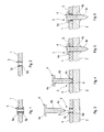
- FIGS. 1 to 6 describe the production according to the invention of a nail joint of two joining parts 1 and 2 to be joined by means of a nail 4 which, according to the known high-speed joining, is driven into a joining region 3 of these two joining parts 1 and 2.
- This method is particularly suitable for joining parts, which consist of a fiber-reinforced plastic and the nail-head-side joining part 1 form (see. FIGS. 3 to 6 ) and hereinafter also referred to as plastic joining part 1.
- the second joining partner is usually a joining part 2 made of a steel or aluminum material.
- the joint connection between such joining parts 1 and 2 is by means of a in the plastic joining part 1 according to the Figures 1 and 2 introduced nail guide sleeve 5 made.
- a nail guide sleeve 5 made of metal is already laminated or cast as an insert or inlay during the production of this plastic joining parts 1.
- the Figures 1 and 2 show two versions of such a nail guide sleeve. 5
- the nail guide sleeve 5 according to FIG. 1 is formed at its two end faces in each case with a radially encircling collar 5 a and 5 b in the manner of a flat head, which in each case rests flat on the surface of the joining part 1.
- the nail guide sleeve 5 according to FIG. 2 On the other hand, it is formed with countersunk-like ends 5c and 5d, so that the end faces are in each case aligned with the surfaces of the joining part 1, that is, they do not protrude beyond the respective surface.
- Such a plastic joining part 1 is placed on the non-perforated joining part 2 as a joining partner, as in FIG. 3 is shown.
- the nail guide sleeve 5 corresponds to the embodiment according to FIG. 2 ,
- the inner diameter of the nail guide sleeve 5 is smaller than the diameter of the nail shank 4b.
- the nail 4 to be driven into the joining region 3 by the nail guide sleeve 5 and the joining part 2 comprises a nail head 4a, a nail shank 4b having a surface profiling and a nail tip 4c.
- the drive according to FIG. 4 shows the state of the nail 4, in which the nail tip 4c is already inserted into the nail guide sleeve 5 and the other joining part 2 begins to penetrate.
- FIG. 5 is the driving ended, ie the nail tip 4c has leaked to form a material Aufsches on the underside of the joining part 2 and the underside of the nail head 4a lies on top of the plastic joining part 1. Since the inner diameter of the nail guide sleeve 5 is smaller than the diameter of the nail shank 5b is, in this driving the nail guide sleeve 5 is widened, whereby a high clamping effect arises.
- FIG. 6 shows a nail connection according to the state FIG. 5 but with a nail guide sleeve 5 whose inner diameter is slightly larger than the diameter of the nail shank 4b. This has the consequence that the plastic joining part 1 is clamped between the nail head 4a and the other joining part 2.
- the properties remain in terms of their strength after joining, since the fibers are not cut or destroyed, as would be the case with a driving of the nail without the nail guide sleeve 5 according to the invention.
- FIGS. 7 to 10 show the method according to the invention, in which the joining part 1 already has a pre-hole 6.
- cover plates are used in body construction, which have production-related pre-holes, so that they can be screwed, for example, by means of self-tapping screws to another joining part. Due to the shorter process time, it would be helpful in many cases to produce such joining points by means of high speed joining, but due to the often too large diameter of these holes is not applicable.
- a nail guide sleeve 5 is inserted as an insert in such a pre-hole 6 of the joining part 1, placed on the non-perforated joining part 2 as a further joining partner and in a joining region 3 by means of a nail 4 made the joint connection, like this in the FIGS. 7 to 10 is shown.
- the outer diameter of the nail guide sleeve 5 corresponds to the diameter of the Vorlochs 6, wherein the inner diameter is smaller than the diameter of the nail shank 4b.
- the nail guide sleeve 5 made of plastic or metal is according to FIG. 7 formed on its nail head side end face with a radially encircling collar 5a in the manner of a flat head, so that this nail guide sleeve 5 can be pressed or eigepresst in the pre-hole 6 of the joining part 1 until this collar 5a rests flat on the surface of the joining part 1.
- the opposite end face of the nail guide sleeve 5 is aligned with the nagelfkopfabgewandten surface of the joining part 1, so that the two joining parts 1 and 2 lie flat against each other.
- the nail 4 to be driven into the joining region 3 through the nail guide sleeve 5 and the joining part 2 comprises according to FIG FIG. 7 a nail head 4a, a surface profiling having nail shank 4b and a nail tip 4c. On the underside of the nail head 4a a nail shaft 4b circumferential annular groove 4d is provided.
- the drive according to FIG. 8 shows in the context of high speed joining the state of the nail 4, in which the nail tip 4c is already inserted into the nail guide sleeve 5 and the nail tip 4c begins to penetrate the second joining part 2.
- the driving ended ie the nail tip 4c has leaked to form a Materialaufschsches on the underside of the joining part 2 and the underside of the nail head 4a is located on the top of the joining part 1, wherein by the collar 5a of the nail guide sleeve 5 a material throw is formed, the the annular groove 4d is received on the underside of the nail head 4a. Since the inner diameter of the nail guide sleeve 5 is smaller than the diameter of the nail shank 4b, the nail guide sleeve 5 is widened in this driving operation, whereby a high clamping effect.
- FIG. 10 shows a nail connection according to the state FIG. 9 but with a nail guide sleeve 5 whose inner diameter is slightly larger than the diameter of the nail shank 4b.
- a nail guide sleeve 5 whose inner diameter is slightly larger than the diameter of the nail shank 4b.
- the plastic joining part 1 is clamped between the nail head 4a and the other joining part 2.
- a part of the collar 5a is received by the annular groove 4d of the nail head 4a when the bottom of the nail head 4a completely rests on the surface of the joining part 1.
- the joint When using a made of plastic nail guide sleeve 5, the joint is sealed against the ingress of moisture and moisture, thereby achieving effective corrosion protection.
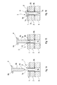
- FIG. 11 shows this situation, in which two aligned pilot holes 7a and 7b in a joining part 1 and a joining part 2 receive a nail guide sleeve 8 as an insert, said nail guide sleeve 8 extends over both superimposed joining parts 1 and 2 and has an outer diameter corresponding to the diameter of the corresponds to two pilot holes 7a and 7b.
- the nail 4 to be driven into the joining region 3 through the nail guide sleeve 8 and the joining part 2 comprises according to FIG FIG. 11 a nail head 4a, a surface profiling having nail shank 4b and a nail tip 4c.
- a nail shaft 4b circumferential annular groove 4d is provided on the underside of the nail head 4a .
- the inner diameter of the nail guide sleeve 8 is smaller than the diameter of the nail shank 4b.
- the nail guide sleeve 8 made of plastic or soft metal is according to FIG. 11 formed on its nail-head-side end face with a radially encircling collar 8a in the manner of a flat head, so that this nail guide sleeve 5 can be pressed or eigepresst in the two pilot holes 7a and 7b of the two joining parts 1 and 2, until this collar 8a flat on the surface of the joining part 1 rests.
- the opposite end face of the nail guide sleeve 5 is aligned with the lower surface of the nail head facing away from the joining part. 2
- the drive according to FIG. 12 shows in the context of high-speed joining the state of the nail 4, in which the nail tip 4c is already partially inserted into the nail guide sleeve 8.
- FIG. 13 is the driving ended, ie the nail tip 4 c has leaked to form a material Aufsches on the underside of the joining part 2 and the underside of the nail head 4 a lies on the top of the joining part 1, wherein by the collar 8 a of the nail guide sleeve 8 a material throw is formed, the the annular groove 4d is received on the underside of the nail head 4a.
- the nail guide sleeve 8 Since the inner diameter of the nail guide sleeve 8 is smaller than the diameter of the nail shank 4b, in this driving operation, the nail guide sleeve 8 is widened and pressed against the hole wall of the pilot hole 7a and 7b, respectively, whereby the connection strength is achieved.
- the nail guide sleeve 8 also from below, that is introduced from the bottom of the nail head facing away from the joining part 2 in the pre-hole 7b so that the collar 8b rests on the underside of the nail head facing away from fitting 2 and the opposite end face of the nail guide sleeve 8 is aligned with the surface of the nail head side joining part 1 ,
- this nail guide sleeve 8 must be supported from below by a perforated die 9, ie the circumferential collar 8a rests on the edge of the perforated die 9.
- the illustrated method steps FIG. 15 and FIG. 16 correspond to those after FIG. 12 and FIG. 13 .
- the driven state of the nail 4 according to FIG. 16 arises on the top of the joining part 1 no material Aufsch, since there is no collar.
- On the underside at the exit point of the nail tip 4c is formed essentially no material throw, as the collar is almost completely supported by the perforated die 9 and the nail tip 4c protrudes into the opening of the perforated die 9.
- the nail guide sleeve 8 is widened and pressed against the hole wall of the pilot holes 7a and 7b, whereby the connection strength is achieved.
- the in the FIGS. 11 to 16 used nail 4 can also be performed with a blunt tip, so essentially without nail tip, since a pre-hole in both parts 1 and 2 is already present. This offers the advantage that the nail tip does not protrude so far on the underside of the joining part 2.
- the nail head-side joining part 1 is connected to a single joining part 2 as a further joining partner.
- the invention can also be carried out with more than just one other joining partner.
Landscapes
- Engineering & Computer Science (AREA)
- General Engineering & Computer Science (AREA)
- Mechanical Engineering (AREA)
- Lining Or Joining Of Plastics Or The Like (AREA)
- Insertion Pins And Rivets (AREA)
- Connection Of Plates (AREA)
Applications Claiming Priority (1)
| Application Number | Priority Date | Filing Date | Title |
|---|---|---|---|
| DE201010035950 DE102010035950A1 (de) | 2010-08-31 | 2010-08-31 | Verfahren zur Herstellung einer Nagelverbindung zwischen wenigstens zwei Fügeteilen |
Publications (3)
| Publication Number | Publication Date |
|---|---|
| EP2423518A2 true EP2423518A2 (fr) | 2012-02-29 |
| EP2423518A3 EP2423518A3 (fr) | 2013-06-05 |
| EP2423518B1 EP2423518B1 (fr) | 2014-07-02 |
Family
ID=45440644
Family Applications (1)
| Application Number | Title | Priority Date | Filing Date |
|---|---|---|---|
| EP20110006741 Not-in-force EP2423518B1 (fr) | 2010-08-31 | 2011-08-18 | Procédé de fabrication d'une liaison par clous entre au moins deux éléments d'assemblage |
Country Status (3)
| Country | Link |
|---|---|
| EP (1) | EP2423518B1 (fr) |
| DE (1) | DE102010035950A1 (fr) |
| ES (1) | ES2486681T3 (fr) |
Cited By (6)
| Publication number | Priority date | Publication date | Assignee | Title |
|---|---|---|---|---|
| WO2013171180A1 (fr) * | 2012-05-14 | 2013-11-21 | Johnson Controls Gmbh | Arrangement de composants, siège de véhicule et procédé de fabrication |
| WO2014086331A1 (fr) * | 2012-12-05 | 2014-06-12 | Eads Deutschland Gmbh | Boulon indicateur permettant de surveiller des assemblages collés de pièces de structure |
| WO2015124425A1 (fr) * | 2014-02-24 | 2015-08-27 | Bayerische Motoren Werke Aktiengesellschaft | Procédé de production d'une liaison par vissage-collage à l'aide d'une vis de formation de trou d'écoulement et vis de formation de trou d'écoulement utilisable à cette fin |
| WO2015135722A1 (fr) * | 2014-03-10 | 2015-09-17 | Bayerische Motoren Werke Aktiengesellschaft | Procédé pour produire une liaison d'adhérence par vis au moyen d'une vis de fluoperçage et emsemble produit au moyen de ce procédé |
| CN110248798A (zh) * | 2017-02-09 | 2019-09-17 | 中车青岛四方机车车辆股份有限公司 | 用于将部件连接至纤维复合结构的连接元件 |
| CN115045897A (zh) * | 2022-07-14 | 2022-09-13 | 柳振安 | 射钉 |
Citations (1)
| Publication number | Priority date | Publication date | Assignee | Title |
|---|---|---|---|---|
| DE102006002238A1 (de) | 2006-01-17 | 2007-07-19 | Böllhoff Verbindungstechnik GmbH | Verfahren zum Herstellen einer Nagelverbindung sowie Nagel hierfür |
Family Cites Families (4)
| Publication number | Priority date | Publication date | Assignee | Title |
|---|---|---|---|---|
| AU486273B2 (en) * | 1972-06-06 | 1974-12-12 | Siddons Industries Limited | Fastener assembly |
| FR2610375A1 (fr) * | 1987-01-30 | 1988-08-05 | Prospection & Inventions | Tampon de fixation de panneau |
| DE4339840B4 (de) * | 1993-11-23 | 2005-04-14 | Hilti Ag | Befestigungselement zum Eintreiben in hartes Aufnahmematerial mittels pulverkraftbetriebener Setzgeräte |
| WO2006019786A1 (fr) * | 2004-07-19 | 2006-02-23 | James Murtha | Adaptateur de profondeur et doigtier préréglés pour vis et clous lors de l'installation d'une plaque de plâtre |
-
2010
- 2010-08-31 DE DE201010035950 patent/DE102010035950A1/de not_active Withdrawn
-
2011
- 2011-08-18 EP EP20110006741 patent/EP2423518B1/fr not_active Not-in-force
- 2011-08-18 ES ES11006741.0T patent/ES2486681T3/es active Active
Patent Citations (1)
| Publication number | Priority date | Publication date | Assignee | Title |
|---|---|---|---|---|
| DE102006002238A1 (de) | 2006-01-17 | 2007-07-19 | Böllhoff Verbindungstechnik GmbH | Verfahren zum Herstellen einer Nagelverbindung sowie Nagel hierfür |
Cited By (12)
| Publication number | Priority date | Publication date | Assignee | Title |
|---|---|---|---|---|
| WO2013171180A1 (fr) * | 2012-05-14 | 2013-11-21 | Johnson Controls Gmbh | Arrangement de composants, siège de véhicule et procédé de fabrication |
| CN104302511A (zh) * | 2012-05-14 | 2015-01-21 | 约翰逊控股公司 | 部件结构、车辆座椅和制造方法 |
| JP2015523508A (ja) * | 2012-05-14 | 2015-08-13 | ジョンソン・コントロールズ・ゲー・エム・ベー・ハー | 部材配列体、車両シート及び製造方法 |
| US9975461B2 (en) | 2012-05-14 | 2018-05-22 | Johnson Controls Gmbh | Arrangement of components, vehicle seat, and production method |
| WO2014086331A1 (fr) * | 2012-12-05 | 2014-06-12 | Eads Deutschland Gmbh | Boulon indicateur permettant de surveiller des assemblages collés de pièces de structure |
| US10071817B2 (en) | 2012-12-05 | 2018-09-11 | Airbus Defence and Space GmbH | Indication bolt for monitoring adhesive bonds in structural elements |
| WO2015124425A1 (fr) * | 2014-02-24 | 2015-08-27 | Bayerische Motoren Werke Aktiengesellschaft | Procédé de production d'une liaison par vissage-collage à l'aide d'une vis de formation de trou d'écoulement et vis de formation de trou d'écoulement utilisable à cette fin |
| US10393165B2 (en) | 2014-02-24 | 2019-08-27 | Bayerische Motoren Werke Aktiengesellschaft | Method for producing an adhesive screw connection using a flow drill screw, and flow drill screw usable therefor |
| WO2015135722A1 (fr) * | 2014-03-10 | 2015-09-17 | Bayerische Motoren Werke Aktiengesellschaft | Procédé pour produire une liaison d'adhérence par vis au moyen d'une vis de fluoperçage et emsemble produit au moyen de ce procédé |
| US10584734B2 (en) | 2014-03-10 | 2020-03-10 | Bayerische Motoren Werke Aktiengesellschaft | Method for producing an adhesive screw connection using a flow drill screw, and composite component produced thereby |
| CN110248798A (zh) * | 2017-02-09 | 2019-09-17 | 中车青岛四方机车车辆股份有限公司 | 用于将部件连接至纤维复合结构的连接元件 |
| CN115045897A (zh) * | 2022-07-14 | 2022-09-13 | 柳振安 | 射钉 |
Also Published As
| Publication number | Publication date |
|---|---|
| DE102010035950A1 (de) | 2012-03-01 |
| EP2423518B1 (fr) | 2014-07-02 |
| ES2486681T3 (es) | 2014-08-19 |
| EP2423518A3 (fr) | 2013-06-05 |
Similar Documents
| Publication | Publication Date | Title |
|---|---|---|
| DE3003908C2 (de) | Stehbolzen mit Stanz- und Nietverhalten | |
| DE102012008798B4 (de) | Verfahren zum Fügen sowie Verbindungselement | |
| EP3111100B1 (fr) | Procédé de production d'une liaison par vissage-collage à l'aide d'une vis de formation de trou d'écoulement et vis de formation de trou d'écoulement utilisable à cette fin | |
| DE102014204449A1 (de) | Verfahren zum Verbinden von Bauteilen von denen eines aus einem faserverstärkten Kunststoff besteht | |
| DE102011108224A1 (de) | Funktionselement mit Verdrehsicherungsmerkmalen sowie Zusammenbauteil bestehend aus dem Funktionselement und einem Blechteil | |
| EP3117109B1 (fr) | Procédé pour produire une liaison d'adhérence par vis au moyen d'une vis de fluoperçage et emsemble produit au moyen de ce procédé | |
| DE102011103545B4 (de) | Verfahren zum Reparieren von stanzgenieteten Werkstücken | |
| DE102011001522B4 (de) | Verbindungselement zur Herstellung einer Verbindung zwischen wenigstens zwei sich überlappenden Bauteilen und Verfahren zur Herstellung dieser Verbindung | |
| EP2423518B1 (fr) | Procédé de fabrication d'une liaison par clous entre au moins deux éléments d'assemblage | |
| DE202009014886U1 (de) | Kugelzapfen | |
| DE102011114306A1 (de) | Verfahren zum Fügen von wenigstens zwei FVK-Bauteilen | |
| DE102007019253B4 (de) | Blindnietmutter | |
| EP2484924A1 (fr) | Liaison bout à bout et procédé de développement d'une liaison bout à bout | |
| DE102014104571A1 (de) | Selbststanzendes Funktionselement und ein Zusammenbauteil bestehend aus dem Funktionselement und einem Blechteil | |
| DE2440353A1 (de) | Befestigungsbolzen | |
| DE102010046318A1 (de) | Fügeelement zum Fügen von wenigstens zwei aneinander liegenden Fügeteilen | |
| DE102014211093A1 (de) | Loch- und gewindeformende Schraube | |
| DE102010039671A1 (de) | Befestigungselement | |
| DE102015008719A1 (de) | Verfahren zur Herstellung eines Bauteilverbunds | |
| DE102015210963A1 (de) | Thermoplastischer Reibverbinder | |
| DE102009035725A1 (de) | Selbstlochender Blindniet | |
| DE102009053853A1 (de) | Verfahren zum Lösen einer zwischen wenigstens zwei Bauteilen mittels eines Nagels hergestellten Nagelverbindung | |
| DE202006000666U1 (de) | Verbindungsanordnung zum Verbinden zweier Bauteile mittels eines Nagels | |
| DE102011089237B4 (de) | Fügeverbindung zwischen mindestens zwei Bauteilen, Bauteilanordnung und Verfahren zum Bereitstellen einer Bauteilanordnung | |
| DE102010025389A1 (de) | Nagel zur Herstellung einer Nagelverbindung |
Legal Events
| Date | Code | Title | Description |
|---|---|---|---|
| AK | Designated contracting states |
Kind code of ref document: A2 Designated state(s): AL AT BE BG CH CY CZ DE DK EE ES FI FR GB GR HR HU IE IS IT LI LT LU LV MC MK MT NL NO PL PT RO RS SE SI SK SM TR |
|
| AX | Request for extension of the european patent |
Extension state: BA ME |
|
| PUAI | Public reference made under article 153(3) epc to a published international application that has entered the european phase |
Free format text: ORIGINAL CODE: 0009012 |
|
| PUAL | Search report despatched |
Free format text: ORIGINAL CODE: 0009013 |
|
| AK | Designated contracting states |
Kind code of ref document: A3 Designated state(s): AL AT BE BG CH CY CZ DE DK EE ES FI FR GB GR HR HU IE IS IT LI LT LU LV MC MK MT NL NO PL PT RO RS SE SI SK SM TR |
|
| AX | Request for extension of the european patent |
Extension state: BA ME |
|
| RIC1 | Information provided on ipc code assigned before grant |
Ipc: F16B 19/14 20060101AFI20130426BHEP Ipc: F16B 5/04 20060101ALI20130426BHEP |
|
| 17P | Request for examination filed |
Effective date: 20131205 |
|
| RBV | Designated contracting states (corrected) |
Designated state(s): AL AT BE BG CH CY CZ DE DK EE ES FI FR GB GR HR HU IE IS IT LI LT LU LV MC MK MT NL NO PL PT RO RS SE SI SK SM TR |
|
| GRAP | Despatch of communication of intention to grant a patent |
Free format text: ORIGINAL CODE: EPIDOSNIGR1 |
|
| INTG | Intention to grant announced |
Effective date: 20140409 |
|
| GRAS | Grant fee paid |
Free format text: ORIGINAL CODE: EPIDOSNIGR3 |
|
| GRAA | (expected) grant |
Free format text: ORIGINAL CODE: 0009210 |
|
| AK | Designated contracting states |
Kind code of ref document: B1 Designated state(s): AL AT BE BG CH CY CZ DE DK EE ES FI FR GB GR HR HU IE IS IT LI LT LU LV MC MK MT NL NO PL PT RO RS SE SI SK SM TR |
|
| REG | Reference to a national code |
Ref country code: GB Ref legal event code: FG4D Free format text: NOT ENGLISH |
|
| REG | Reference to a national code |
Ref country code: CH Ref legal event code: EP Ref country code: AT Ref legal event code: REF Ref document number: 676086 Country of ref document: AT Kind code of ref document: T Effective date: 20140715 |
|
| REG | Reference to a national code |
Ref country code: IE Ref legal event code: FG4D Free format text: LANGUAGE OF EP DOCUMENT: GERMAN |
|
| REG | Reference to a national code |
Ref country code: SE Ref legal event code: TRGR |
|
| REG | Reference to a national code |
Ref country code: DE Ref legal event code: R096 Ref document number: 502011003602 Country of ref document: DE Effective date: 20140814 |
|
| REG | Reference to a national code |
Ref country code: ES Ref legal event code: FG2A Ref document number: 2486681 Country of ref document: ES Kind code of ref document: T3 Effective date: 20140819 |
|
| REG | Reference to a national code |
Ref country code: NL Ref legal event code: VDEP Effective date: 20140702 |
|
| REG | Reference to a national code |
Ref country code: LT Ref legal event code: MG4D |
|
| PG25 | Lapsed in a contracting state [announced via postgrant information from national office to epo] |
Ref country code: NO Free format text: LAPSE BECAUSE OF FAILURE TO SUBMIT A TRANSLATION OF THE DESCRIPTION OR TO PAY THE FEE WITHIN THE PRESCRIBED TIME-LIMIT Effective date: 20141002 Ref country code: FI Free format text: LAPSE BECAUSE OF FAILURE TO SUBMIT A TRANSLATION OF THE DESCRIPTION OR TO PAY THE FEE WITHIN THE PRESCRIBED TIME-LIMIT Effective date: 20140702 Ref country code: GR Free format text: LAPSE BECAUSE OF FAILURE TO SUBMIT A TRANSLATION OF THE DESCRIPTION OR TO PAY THE FEE WITHIN THE PRESCRIBED TIME-LIMIT Effective date: 20141003 Ref country code: BG Free format text: LAPSE BECAUSE OF FAILURE TO SUBMIT A TRANSLATION OF THE DESCRIPTION OR TO PAY THE FEE WITHIN THE PRESCRIBED TIME-LIMIT Effective date: 20141002 Ref country code: PT Free format text: LAPSE BECAUSE OF FAILURE TO SUBMIT A TRANSLATION OF THE DESCRIPTION OR TO PAY THE FEE WITHIN THE PRESCRIBED TIME-LIMIT Effective date: 20141103 Ref country code: CZ Free format text: LAPSE BECAUSE OF FAILURE TO SUBMIT A TRANSLATION OF THE DESCRIPTION OR TO PAY THE FEE WITHIN THE PRESCRIBED TIME-LIMIT Effective date: 20140702 Ref country code: LT Free format text: LAPSE BECAUSE OF FAILURE TO SUBMIT A TRANSLATION OF THE DESCRIPTION OR TO PAY THE FEE WITHIN THE PRESCRIBED TIME-LIMIT Effective date: 20140702 |
|
| PG25 | Lapsed in a contracting state [announced via postgrant information from national office to epo] |
Ref country code: IS Free format text: LAPSE BECAUSE OF FAILURE TO SUBMIT A TRANSLATION OF THE DESCRIPTION OR TO PAY THE FEE WITHIN THE PRESCRIBED TIME-LIMIT Effective date: 20141102 Ref country code: LV Free format text: LAPSE BECAUSE OF FAILURE TO SUBMIT A TRANSLATION OF THE DESCRIPTION OR TO PAY THE FEE WITHIN THE PRESCRIBED TIME-LIMIT Effective date: 20140702 Ref country code: PL Free format text: LAPSE BECAUSE OF FAILURE TO SUBMIT A TRANSLATION OF THE DESCRIPTION OR TO PAY THE FEE WITHIN THE PRESCRIBED TIME-LIMIT Effective date: 20140702 Ref country code: RS Free format text: LAPSE BECAUSE OF FAILURE TO SUBMIT A TRANSLATION OF THE DESCRIPTION OR TO PAY THE FEE WITHIN THE PRESCRIBED TIME-LIMIT Effective date: 20140702 Ref country code: HR Free format text: LAPSE BECAUSE OF FAILURE TO SUBMIT A TRANSLATION OF THE DESCRIPTION OR TO PAY THE FEE WITHIN THE PRESCRIBED TIME-LIMIT Effective date: 20140702 Ref country code: CY Free format text: LAPSE BECAUSE OF FAILURE TO SUBMIT A TRANSLATION OF THE DESCRIPTION OR TO PAY THE FEE WITHIN THE PRESCRIBED TIME-LIMIT Effective date: 20140702 Ref country code: NL Free format text: LAPSE BECAUSE OF FAILURE TO SUBMIT A TRANSLATION OF THE DESCRIPTION OR TO PAY THE FEE WITHIN THE PRESCRIBED TIME-LIMIT Effective date: 20140702 |
|
| REG | Reference to a national code |
Ref country code: CH Ref legal event code: PL |
|
| REG | Reference to a national code |
Ref country code: DE Ref legal event code: R097 Ref document number: 502011003602 Country of ref document: DE |
|
| PG25 | Lapsed in a contracting state [announced via postgrant information from national office to epo] |
Ref country code: LI Free format text: LAPSE BECAUSE OF NON-PAYMENT OF DUE FEES Effective date: 20140831 Ref country code: DK Free format text: LAPSE BECAUSE OF FAILURE TO SUBMIT A TRANSLATION OF THE DESCRIPTION OR TO PAY THE FEE WITHIN THE PRESCRIBED TIME-LIMIT Effective date: 20140702 Ref country code: BE Free format text: LAPSE BECAUSE OF NON-PAYMENT OF DUE FEES Effective date: 20140831 Ref country code: RO Free format text: LAPSE BECAUSE OF FAILURE TO SUBMIT A TRANSLATION OF THE DESCRIPTION OR TO PAY THE FEE WITHIN THE PRESCRIBED TIME-LIMIT Effective date: 20140702 Ref country code: CH Free format text: LAPSE BECAUSE OF NON-PAYMENT OF DUE FEES Effective date: 20140831 Ref country code: MC Free format text: LAPSE BECAUSE OF FAILURE TO SUBMIT A TRANSLATION OF THE DESCRIPTION OR TO PAY THE FEE WITHIN THE PRESCRIBED TIME-LIMIT Effective date: 20140702 Ref country code: SK Free format text: LAPSE BECAUSE OF FAILURE TO SUBMIT A TRANSLATION OF THE DESCRIPTION OR TO PAY THE FEE WITHIN THE PRESCRIBED TIME-LIMIT Effective date: 20140702 Ref country code: EE Free format text: LAPSE BECAUSE OF FAILURE TO SUBMIT A TRANSLATION OF THE DESCRIPTION OR TO PAY THE FEE WITHIN THE PRESCRIBED TIME-LIMIT Effective date: 20140702 |
|
| PLBE | No opposition filed within time limit |
Free format text: ORIGINAL CODE: 0009261 |
|
| STAA | Information on the status of an ep patent application or granted ep patent |
Free format text: STATUS: NO OPPOSITION FILED WITHIN TIME LIMIT |
|
| REG | Reference to a national code |
Ref country code: IE Ref legal event code: MM4A |
|
| 26N | No opposition filed |
Effective date: 20150407 |
|
| REG | Reference to a national code |
Ref country code: FR Ref legal event code: PLFP Year of fee payment: 5 |
|
| PG25 | Lapsed in a contracting state [announced via postgrant information from national office to epo] |
Ref country code: IE Free format text: LAPSE BECAUSE OF NON-PAYMENT OF DUE FEES Effective date: 20140818 |
|
| PG25 | Lapsed in a contracting state [announced via postgrant information from national office to epo] |
Ref country code: SI Free format text: LAPSE BECAUSE OF FAILURE TO SUBMIT A TRANSLATION OF THE DESCRIPTION OR TO PAY THE FEE WITHIN THE PRESCRIBED TIME-LIMIT Effective date: 20140702 |
|
| GBPC | Gb: european patent ceased through non-payment of renewal fee |
Effective date: 20150818 |
|
| PG25 | Lapsed in a contracting state [announced via postgrant information from national office to epo] |
Ref country code: SM Free format text: LAPSE BECAUSE OF FAILURE TO SUBMIT A TRANSLATION OF THE DESCRIPTION OR TO PAY THE FEE WITHIN THE PRESCRIBED TIME-LIMIT Effective date: 20140702 |
|
| PG25 | Lapsed in a contracting state [announced via postgrant information from national office to epo] |
Ref country code: MT Free format text: LAPSE BECAUSE OF FAILURE TO SUBMIT A TRANSLATION OF THE DESCRIPTION OR TO PAY THE FEE WITHIN THE PRESCRIBED TIME-LIMIT Effective date: 20140702 |
|
| PG25 | Lapsed in a contracting state [announced via postgrant information from national office to epo] |
Ref country code: LU Free format text: LAPSE BECAUSE OF NON-PAYMENT OF DUE FEES Effective date: 20140818 Ref country code: TR Free format text: LAPSE BECAUSE OF FAILURE TO SUBMIT A TRANSLATION OF THE DESCRIPTION OR TO PAY THE FEE WITHIN THE PRESCRIBED TIME-LIMIT Effective date: 20140702 Ref country code: GB Free format text: LAPSE BECAUSE OF NON-PAYMENT OF DUE FEES Effective date: 20150818 Ref country code: HU Free format text: LAPSE BECAUSE OF FAILURE TO SUBMIT A TRANSLATION OF THE DESCRIPTION OR TO PAY THE FEE WITHIN THE PRESCRIBED TIME-LIMIT; INVALID AB INITIO Effective date: 20110818 |
|
| REG | Reference to a national code |
Ref country code: FR Ref legal event code: PLFP Year of fee payment: 6 |
|
| REG | Reference to a national code |
Ref country code: FR Ref legal event code: PLFP Year of fee payment: 7 |
|
| REG | Reference to a national code |
Ref country code: AT Ref legal event code: MM01 Ref document number: 676086 Country of ref document: AT Kind code of ref document: T Effective date: 20160818 |
|
| PG25 | Lapsed in a contracting state [announced via postgrant information from national office to epo] |
Ref country code: AT Free format text: LAPSE BECAUSE OF NON-PAYMENT OF DUE FEES Effective date: 20160818 |
|
| PG25 | Lapsed in a contracting state [announced via postgrant information from national office to epo] |
Ref country code: MK Free format text: LAPSE BECAUSE OF FAILURE TO SUBMIT A TRANSLATION OF THE DESCRIPTION OR TO PAY THE FEE WITHIN THE PRESCRIBED TIME-LIMIT Effective date: 20140702 |
|
| REG | Reference to a national code |
Ref country code: FR Ref legal event code: PLFP Year of fee payment: 8 |
|
| PG25 | Lapsed in a contracting state [announced via postgrant information from national office to epo] |
Ref country code: AL Free format text: LAPSE BECAUSE OF FAILURE TO SUBMIT A TRANSLATION OF THE DESCRIPTION OR TO PAY THE FEE WITHIN THE PRESCRIBED TIME-LIMIT Effective date: 20140702 |
|
| PGFP | Annual fee paid to national office [announced via postgrant information from national office to epo] |
Ref country code: ES Payment date: 20190912 Year of fee payment: 9 Ref country code: IT Payment date: 20190830 Year of fee payment: 9 Ref country code: SE Payment date: 20190826 Year of fee payment: 9 |
|
| REG | Reference to a national code |
Ref country code: SE Ref legal event code: EUG |
|
| PG25 | Lapsed in a contracting state [announced via postgrant information from national office to epo] |
Ref country code: SE Free format text: LAPSE BECAUSE OF NON-PAYMENT OF DUE FEES Effective date: 20200819 |
|
| PG25 | Lapsed in a contracting state [announced via postgrant information from national office to epo] |
Ref country code: IT Free format text: LAPSE BECAUSE OF NON-PAYMENT OF DUE FEES Effective date: 20200818 |
|
| REG | Reference to a national code |
Ref country code: ES Ref legal event code: FD2A Effective date: 20220110 |
|
| PG25 | Lapsed in a contracting state [announced via postgrant information from national office to epo] |
Ref country code: ES Free format text: LAPSE BECAUSE OF NON-PAYMENT OF DUE FEES Effective date: 20200819 |
|
| PGFP | Annual fee paid to national office [announced via postgrant information from national office to epo] |
Ref country code: DE Payment date: 20220831 Year of fee payment: 12 |
|
| PGFP | Annual fee paid to national office [announced via postgrant information from national office to epo] |
Ref country code: FR Payment date: 20220824 Year of fee payment: 12 |
|
| P01 | Opt-out of the competence of the unified patent court (upc) registered |
Effective date: 20230530 |
|
| REG | Reference to a national code |
Ref country code: DE Ref legal event code: R119 Ref document number: 502011003602 Country of ref document: DE |
|
| PG25 | Lapsed in a contracting state [announced via postgrant information from national office to epo] |
Ref country code: FR Free format text: LAPSE BECAUSE OF NON-PAYMENT OF DUE FEES Effective date: 20230831 Ref country code: DE Free format text: LAPSE BECAUSE OF NON-PAYMENT OF DUE FEES Effective date: 20240301 |