EP2423629B1 - Plattenwärmetauscher in gedichteter Ausführung - Google Patents
Plattenwärmetauscher in gedichteter Ausführung Download PDFInfo
- Publication number
- EP2423629B1 EP2423629B1 EP11178694.3A EP11178694A EP2423629B1 EP 2423629 B1 EP2423629 B1 EP 2423629B1 EP 11178694 A EP11178694 A EP 11178694A EP 2423629 B1 EP2423629 B1 EP 2423629B1
- Authority
- EP
- European Patent Office
- Prior art keywords
- heat exchanger
- plate heat
- elements
- closed profile
- profile elements
- Prior art date
- Legal status (The legal status is an assumption and is not a legal conclusion. Google has not performed a legal analysis and makes no representation as to the accuracy of the status listed.)
- Active
Links
- 238000007789 sealing Methods 0.000 claims description 5
- 238000004519 manufacturing process Methods 0.000 description 4
- 229910000831 Steel Inorganic materials 0.000 description 1
- 210000001015 abdomen Anatomy 0.000 description 1
- 230000001419 dependent effect Effects 0.000 description 1
- 239000012530 fluid Substances 0.000 description 1
- 239000000463 material Substances 0.000 description 1
- 239000004033 plastic Substances 0.000 description 1
- 229920003023 plastic Polymers 0.000 description 1
- 238000005476 soldering Methods 0.000 description 1
- 239000010959 steel Substances 0.000 description 1
- 229920001169 thermoplastic Polymers 0.000 description 1
- 239000004416 thermosoftening plastic Substances 0.000 description 1
- 238000003466 welding Methods 0.000 description 1
Images


Classifications
-
- F—MECHANICAL ENGINEERING; LIGHTING; HEATING; WEAPONS; BLASTING
- F28—HEAT EXCHANGE IN GENERAL
- F28D—HEAT-EXCHANGE APPARATUS, NOT PROVIDED FOR IN ANOTHER SUBCLASS, IN WHICH THE HEAT-EXCHANGE MEDIA DO NOT COME INTO DIRECT CONTACT
- F28D9/00—Heat-exchange apparatus having stationary plate-like or laminated conduit assemblies for both heat-exchange media, the media being in contact with different sides of a conduit wall
- F28D9/0031—Heat-exchange apparatus having stationary plate-like or laminated conduit assemblies for both heat-exchange media, the media being in contact with different sides of a conduit wall the conduits for one heat-exchange medium being formed by paired plates touching each other
- F28D9/0043—Heat-exchange apparatus having stationary plate-like or laminated conduit assemblies for both heat-exchange media, the media being in contact with different sides of a conduit wall the conduits for one heat-exchange medium being formed by paired plates touching each other the plates having openings therein for circulation of at least one heat-exchange medium from one conduit to another
- F28D9/005—Heat-exchange apparatus having stationary plate-like or laminated conduit assemblies for both heat-exchange media, the media being in contact with different sides of a conduit wall the conduits for one heat-exchange medium being formed by paired plates touching each other the plates having openings therein for circulation of at least one heat-exchange medium from one conduit to another the plates having openings therein for both heat-exchange media
-
- F—MECHANICAL ENGINEERING; LIGHTING; HEATING; WEAPONS; BLASTING
- F28—HEAT EXCHANGE IN GENERAL
- F28F—DETAILS OF HEAT-EXCHANGE AND HEAT-TRANSFER APPARATUS, OF GENERAL APPLICATION
- F28F3/00—Plate-like or laminated elements; Assemblies of plate-like or laminated elements
- F28F3/08—Elements constructed for building-up into stacks, e.g. capable of being taken apart for cleaning
- F28F3/083—Elements constructed for building-up into stacks, e.g. capable of being taken apart for cleaning capable of being taken apart
-
- F—MECHANICAL ENGINEERING; LIGHTING; HEATING; WEAPONS; BLASTING
- F28—HEAT EXCHANGE IN GENERAL
- F28F—DETAILS OF HEAT-EXCHANGE AND HEAT-TRANSFER APPARATUS, OF GENERAL APPLICATION
- F28F9/00—Casings; Header boxes; Auxiliary supports for elements; Auxiliary members within casings
- F28F9/001—Casings in the form of plate-like arrangements; Frames enclosing a heat exchange core
-
- F—MECHANICAL ENGINEERING; LIGHTING; HEATING; WEAPONS; BLASTING
- F28—HEAT EXCHANGE IN GENERAL
- F28F—DETAILS OF HEAT-EXCHANGE AND HEAT-TRANSFER APPARATUS, OF GENERAL APPLICATION
- F28F9/00—Casings; Header boxes; Auxiliary supports for elements; Auxiliary members within casings
- F28F9/007—Auxiliary supports for elements
- F28F9/0075—Supports for plates or plate assemblies
-
- F—MECHANICAL ENGINEERING; LIGHTING; HEATING; WEAPONS; BLASTING
- F28—HEAT EXCHANGE IN GENERAL
- F28F—DETAILS OF HEAT-EXCHANGE AND HEAT-TRANSFER APPARATUS, OF GENERAL APPLICATION
- F28F2275/00—Fastening; Joining
- F28F2275/12—Fastening; Joining by methods involving deformation of the elements
- F28F2275/127—Fastening; Joining by methods involving deformation of the elements by shrinking
-
- F—MECHANICAL ENGINEERING; LIGHTING; HEATING; WEAPONS; BLASTING
- F28—HEAT EXCHANGE IN GENERAL
- F28F—DETAILS OF HEAT-EXCHANGE AND HEAT-TRANSFER APPARATUS, OF GENERAL APPLICATION
- F28F2275/00—Fastening; Joining
- F28F2275/20—Fastening; Joining with threaded elements
Definitions
- the invention relates to a plate heat exchanger in sealed design.
- Plate heat exchangers are known in various designs. These include in particular sealed, soldered and welded plate heat exchangers. Common to the various types is commonly that a stacked arrangement is formed with a front and a rear end plate between which a plurality of heat exchanger plates are received and stacked, such that between the heat exchanger plates cavities are formed, which receive several heat exchange media or fluids in operation. Usually, the cavities are flowed through by the heat exchange media.
- FIG. 1 shows a perspective view of a known plate heat exchanger in a sealed design, in which between two printing frame plates 1, 2, a stack 3 is arranged with heat exchanger plates.
- the tensioning device for biasing the stacked arrangement is formed with tie rods 4 which connect the two end plates 1, 2 in overlapping areas 5.
- the tie rods 4 are provided with screw thread, so that an external pressure is adjustable.
- a plate heat exchanger is known.
- a stack of heat exchanger plates is disposed between a base and a termination component. Locking screws serve to tension the stack of heat exchanger plates.
- the object of the invention is to provide an improved plate heat exchanger in a sealed design, which is less expensive and can be produced with optimized design.
- the cross-section of the clamping device on the inside is adapted to the outer contour of the stacked arrangement, at least in the at least one corner region, within the scope of customary manufacturing tolerances. It can also be provided that the positive engagement is formed in several or even all corner regions. The latter is given, for example, when the clamping device, the stacked arrangement is formed completely encompassing form-fitting manner.
- a preferred embodiment of the invention may provide that the clamping device rests substantially continuously on the outer surface of an associated portion of the stacked arrangement in the at least one form-fitting embraced portion of the stacked arrangement.
- a heat exchanger is first provided which has a smaller size compared with the prior art, since it is not necessary to pass tie rods laterally past the stacked heat exchanger plates to connect laterally projecting portions of the end plates for the tensioning device. Rather, the clamping device surrounds the stacked at least in a corner region Arrangement form-fitting, so that here the side of the stacked arrangement a reduced or even no space is required, especially for clamping elements.
- the tensioning device is formed with a plurality of closed profile elements and optionally one or more flexible tension straps, which respectively embrace the stacked arrangement.
- the straps are preferably formed from one of the following materials: steel, plastics and thermoplastics.
- the one or more straps are threaded onto the stacked assembly by mechanical tensioning and / or shrinking.
- the plurality of closed profile elements can be formed for example as a square profile or tube. Profile elements in this or other embodiments are available as such in different variants at low cost. In this way, the manufacturing costs are minimized overall.
- the closed profile elements are pushed from the front side to the stacked arrangement with end plates and arranged therebetween heat exchanger plates. This happens in at least one side not yet mounted connections. The connections can then be mounted after the sliding of the closed profile elements.
- the chuck may be formed with a continuous, continuous profile member which extends around the stacked assembly encompassing a portion of at least 50% of the length of the portion of the stacked assembly between terminals on the terminal plate.
- the continuous closed profile element forms a kind of "belly band" in the region of the stacked arrangement between the terminals.
- a preferred embodiment provides that the continuous closed profile element extends over a range of at least 75% of the length of the stacked arrangement between the terminals. It is further preferred that the continuous closed profile element covers a length of at least 90% of the area between the terminals.
- the section of the stacked Arrangement between the terminals may be wholly or partially surrounded by one or more closed profile elements.
- clamping device is formed with a continuous closed profile element, which extends around the stacked arrangement encompassing the entire length of the plate heat exchanger.
- the plurality of closed profile elements in the longitudinal direction of the stacked arrangement all or at least in pairs have a substantially equal width.
- An advantageous embodiment of the invention provides that the closed profile elements are formed from a standard profile element.
- the use of standard profile elements supports a further cost reduction, since such profile elements are available as frequently produced products in various designs at low cost.
- a further development of the invention provides that wall sections of the several closed profile elements are formed as compartment profiles.
- a flat design of the wall sections of the closed profile elements further supports the minimized space requirement of the plate heat exchanger.
- the tensioning device is formed with adjustable biasing elements which are arranged on the one of the plurality of closed profile elements.
- the adjustable biasing members are formed by screw members which are threaded in associated threaded portions in the one or more closed profile members.
- the screw elements can then be screwed in so far that they finally press against the stacked arrangement.
- such screw elements are provided only on the front or only on the back of the stacked arrangement of the closed profile elements.
- the stacked arrangement is then pressed flat against the inside of the closed profile element.
- the adjustable biasing members are configured to apply the outer clamping pressure to the stacked assembly, preferably substantially symmetrically.
- the adjustable biasing elements are formed at one or all closed profile elements in the transverse direction of the stacked arrangement spaced from each other.
- a development of the invention provides that the plurality of closed profile elements connecting areas, in which terminals are arranged on the terminal plate, are formed free.
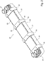
- Fig. 2 11 shows a perspective view of a plate heat exchanger 20 in a sealed design, in which stacked heat exchanger plates 24 are arranged in a stacked arrangement 21 between a front end plate 22 and a rear end plate 23, which is designed as a connection plate.
- the stacked assembly 21 is in a bedplate 22 and a rear end plate 23, which is designed as a connection plate, stacked heat exchanger plates 24 are arranged.
- the stacked assembly 21 is encompassed by a plurality of closed profile elements 28 in a region 25 between terminals 26, 27.
- the plurality of closed profile elements 28 have a substantially uniform distance to each other.
- the portion between the terminals 26, 27 is completely or partially encompassed by a single closed profile element. It can also be provided that a plurality of closed profile elements substantially completely surround the area between the connections 26, 27 together.
- each of the plurality of closed profile elements 28 screws 29, 30 are provided, which are screwed into associated threaded portions, so that the screws 29, 30 press against the rear end plate 23, whereby a bias voltage is generated.
- additional screws may be provided in the closed profile elements 28.
- standard profiles can be used, which preferably meet the usual DIN standards.
- the Fig. 3 to 5 show a schematic representation of the plate heat exchanger 20 Fig. 2 from the side, from the front and from behind.
- FIG. 6 a perspective view of the plate heat exchanger in the Fig. 2 to 5 used closed profile elements 28.
- Fig. 7 shows a perspective view of a plate heat exchanger 20 in a sealed design, in which a continuous closed profile element 31 extends over the entire length of the plate heat exchanger 20 This embodiment is not part of the invention.
Landscapes
- Engineering & Computer Science (AREA)
- Physics & Mathematics (AREA)
- Thermal Sciences (AREA)
- Mechanical Engineering (AREA)
- General Engineering & Computer Science (AREA)
- Heat-Exchange Devices With Radiators And Conduit Assemblies (AREA)
Description
- Die Erfindung betrifft einen Plattenwärmetauscher in gedichteter Ausführung.
- Plattenwärmetauscher sind in verschiedenen Bauformen bekannt. Hierzu gehören insbesondere gedichtete, gelötete und geschweißte Plattenwärmetauscher. Gemeinsam ist den verschiedenen Bauarten üblicherweise, dass eine gestapelte Anordnung mit einer vorderseitigen und einer rückseitigen Endplatte gebildet ist, zwischen denen mehrere Wärmetauscherplatten aufgenommen und gestapelt sind, derart, dass zwischen den Wärmetauscherplatten Hohlräume gebildet sind, die im Betrieb mehrere Wärmetauschermedien oder -fluide aufnehmen. Üblicherweise werden die Hohlräume von den Wärmetauschermedien durchströmt.
- Während bei der gelöteten und der geschweißten Ausführung ein Abdichten der Hohlräume mittels Löt- oder Schweißverbindung erfolgt, sind bei Plattenwärmetauschern in gedichteter Ausführung Dichtungselemente vorgesehen, die in der gestapelten Anordnung die Hohlräume abdichtend angeordnet sind. Gedichtete Plattenwärmetauscher weisen sodann eine Spannvorrichtung auf, die konfiguriert ist, die gestapelte Anordnung mit Endplatten und Wärmetauscherplatten sowie Dichtungselementen vorzuspannen, indem mit Hilfe der Spannvorrichtung ein äußerer Spanndruck aufgegeben wird.
Fig. 1 zeigt eine perspektivische Darstellung eines bekannten Plattenwärmetauschers in gedichteter Ausführung, bei dem zwischen zwei Druckgestellplatten 1, 2 ein Stapel 3 mit Wärmetauscherplatten angeordnet ist. Die Spannvorrichtung zum Vorspannen der gestapelten Anordnung ist mit Zugstangen 4 gebildet, die in übergreifenden Bereichen 5 die beiden Endplatten 1, 2 verbinden. Die Zugstangen 4 sind mit Schraubgewinde versehen, so dass ein äußerer Druck einstellbar ist. - Aus dem Dokument
GB 2,151,347 A - Im Dokument
US 6,098,701 ist ein Plattenwärmetauscher offenbart, der einen Stapel Wärmetauscherplatten aufweist. Zur Minderung des Drucks im Kantenbereich einer Spannvorrichtung sind die vorder- und die Rückseitige Endplatte jeweils mit einer äußeren Krümmung gebildet. - Aufgabe der Erfindung ist es, einen verbesserten Plattenwärmetauscher in gedichteter Ausführung zu schaffen, welcher kostengünstiger und mit optimierter Bauform herstellbar ist.
- Diese Aufgabe wird erfindungsgemäß durch einen Plattenwärmetauscher in gedichteter Ausführung nach dem unabhängigen Anspruch 1 gelöst. Vorteilhafte Ausgestaltungen der Erfindung sind Gegenstand von abhängigen Unteransprüchen.
- Der Querschnitt der Spannvorrichtung auf der Innenseite, nämlich der der gestapelten Anordnung zugewandten Seite, ist im Rahmen üblicher Fertigungstoleranzen zumindest in dem wenigstens einen Eckbereich an die äußere Kontur der gestapelten Anordnung angepasst. Es kann auch vorgesehen sein, dass die Formschlüssigkeit in mehreren oder sogar allen Eckbereichen ausgebildet ist. Letzteres ist zum Beispiel gegeben, wenn die Spannvorrichtung die gestapelte Anordnung vollständig formschlüssig umgreifend gebildet ist.
- Eine bevorzugte Ausbildung der Erfindung kann vorsehen, dass die Spannvorrichtung in dem wenigstens einen formschlüssig umgriffenen Abschnitt der gestapelten Anordnung im Wesentlichen durchgehend auf der äußeren Oberfläche eines zugeordneten Abschnitts der gestapelten Anordnung aufliegt.
- Mit Hilfe des vorgeschlagenen Plattenwärmetauschers ist zunächst ein Wärmetauscher geschaffen, der im Vergleich zum Stand der Technik eine geringere Baugröße aufweist, da es nicht notwendig ist, Zugstangen seitlich an den gestapelten Wärmetauscherplatten vorbeizuführen, um seitlich überstehende Abschnitte der Endplatten für die Spannvorrichtung zu verbinden. Vielmehr umgreift die Spannvorrichtung wenigstens in einem Eckbereich die gestapelte Anordnung formschlüssig, so dass hier seitlich der gestapelten Anordnung ein verminderter oder sogar gar kein Platzbedarf besteht, insbesondere für Spannelemente.
- Die Spannvorrichtung ist mit mehreren geschlossenen Profilelementen und wahlweise einem oder mehreren flexiblen Spannbändern gebildet, die die gestapelte Anordnung jeweils umgreifen. Die Spannbänder sind bevorzugt aus einem Material aus der Gruppe der folgenden Materialien gebildet: Stahl, Kunststoffe und thermoplastische Stoffe. Bei der Herstellung des Plattenwärmetauschers werden das eine oder die mehreren Spannbänder mittels mechanischen Spannens und / oder Aufschrumpfens auf die gestapelten Anordnung aufgezogen.
- Die mehreren geschlossenen Profilelemente können beispielsweise als Vierkantprofil oder -rohr gebildet sein. Profilelemente in dieser oder anderen Ausführungsformen stehen als solche in unterschiedlichen Varianten kostengünstig zur Verfügung. Auf diese Weise werden die Herstellungskosten insgesamt minimiert.
- Bei der Herstellung des Plattenwärmetauschers werden die geschlossenen Profilelemente von der Stirnseite auf die gestapelte Anordnung mit Endplatten und hierzwischen angeordneten Wärmetauscherplatten aufgeschoben. Dieses geschieht bei wenigstens einseitig noch nicht montierten Anschlüssen. Die Anschlüsse können dann nach dem Aufschieben der geschlossenen Profilelemente montiert werden. Die Spannvorrichtung kann mit einem durchgehenden geschlossenen Profilelement gebildet sein, welches sich die gestapelte Anordnung umgreifend über einen Bereich von wenigstens 50% der Länge des Abschnittes der gestapelten Anordnung zwischen Anschlüssen an der Anschlussplatte erstreckt. Bei dieser Ausführungsform, welche nicht Teil der Erfindung ist, bildet das durchgehende geschlossene Profilelement eine Art "Bauchbinde" im Bereich der gestapelten Anordnung zwischen den Anschlüssen. Eine bevorzugte Weiterbildung sieht vor, dass sich das durchgehende geschlossene Profilelement über einen Bereich von wenigstens 75% der Länge der gestapelten Anordnung zwischen den Anschlüssen erstreckt. Weiter bevorzugt ist, dass das durchgehende geschlossene Profilelement eine Länge von wenigstens 90% des Bereiches zwischen den Anschlüssen erfasst. Der Abschnitt der gestapelten Anordnung zwischen den Anschlüssen kann ganz oder teilweise von einem oder mehreren geschlossenen Profilelementen umgriffen sein.
- Ebenfalls nicht Teil der Erfindung ist eine Ausführungsform, bei der die Spannvorrichtung mit einem durchgehenden geschlossenen Profilelement gebildet ist, welches sich die gestapelte Anordnung umgreifend über die gesamte Länge des Plattenwärmetauschers erstreckt.
- Bei einer zweckmäßigen Ausgestaltung der Erfindung kann vorgesehen sein, dass die mehreren geschlossenen Profilelemente in Längsrichtung der gestapelten Anordnung alle oder wenigstens paarweise eine im Wesentlichen gleiche Breite aufweisen.
- Eine vorteilhafte Ausführungsform der Erfindung sieht vor, dass die geschlossenen Profilelemente aus einem Normprofilelement gebildet sind. Die Verwendung von Normprofilelementen unterstützt eine weitere Kostenreduzierung, da derartige Profilelemente als häufig hergestellte Produkte in verschiedenen Bauformen kostengünstig zur Verfügung stehen.
- Bevorzugt sieht eine Fortbildung der Erfindung vor, dass Wandabschnitte der mehreren geschlossenen Profilelemente als Fachprofile gebildet sind. Eine flache Bauform der Wandabschnitte der geschlossenen Profilelemente unterstützt weiter den minimierten Raumbedarf des Plattenwärmetauschers.
- Die Spannvorrichtung ist mit einstellbaren Vorspannelementen gebildet, die an dem einen der mehreren geschlossenen Profilelemente angeordnet sind. Die einstellbaren Vorspannelemente sind von Schraubenelementen gebildet, die in zugeordneter Gewindeabschnitte in dem einen oder den mehreren geschlossenen Profilelementen eingeschraubt werden. Die Schraubenelemente können dann so weit eingedreht werden, dass sie schließlich gegen die gestapelte Anordnung drücken. Bevorzugt sind derartige Schraubenelemente nur auf der Vorder- oder nur auf der Rückseite der gestapelten Anordnung an den geschlossenen Profilelementen vorgesehen. Auf der gegenüberliegenden Seite wird die gestapelte Anordnung dann flächig gegen die Innenseite des geschlossenen Profilelementes gedrückt.
- Die einstellbaren Vorspannelemente sind konfiguriert, den äußeren Spanndruck auf die gestapelte Anordnung einzuleiten, vorzugsweise im Wesentlichen mittelsymmetrisch.
- Bei einer zweckmäßigen Ausgestaltung der Erfindung kann vorgesehen sein, dass die einstellbaren Vorspannelemente an einem oder allen geschlossenen Profilelementen in Querrichtung der gestapelten Anordnung beabstandet voneinander gebildet sind.
- Bevorzugt sieht eine Fortbildung der Erfindung vor, dass die mehreren geschlossenen Profilelemente Anschlussbereiche, in welchen an der Anschlussplatte Anschlüsse angeordnet sind, freilassend gebildet sind.
- Die Erfindung wird im Folgenden anhand von bevorzugten Ausführungsbeispielen unter Bezugnahme auf Figuren einer Zeichnung näher erläutert. Hierbei zeigen:
- Fig. 1
- eine perspektivische Darstellung eines Plattenwärmetauschers in gedichteter Ausführung nach dem Stand der Technik,
- Fig. 2
- eine perspektivische Darstellung eines Plattenwärmetauschers in gedichteter Ausführung, bei dem eine Spannvorrichtung mit mehreren geschlossenen Profilelementen gebildet ist,
- Fig. 3
- eine Darstellung des Plattenwärmetauschers aus
Fig. 2 von der Seite, - Fig. 4
- eine Darstellung des Plattenwärmetauschers aus
Fig. 2 von vorn, - Fig. 5
- eine Darstellung des Plattenwärmetauschers aus
Fig. 2 von hinten, - Fig. 6
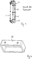
- eine perspektivische Darstellung eines geschlossenen Profilelementes der Spannvorrichtung bei dem Plattenwärmetauscher in den
Fig. 2 bis 5 und - Fig. 7
- eine perspektivische Darstellung eines Plattenwärmetauschers in gedichteter Ausführung, bei dem eine Spannvorrichtung mit einem durchgehenden geschlossenen Profilelement über die gesamte Länge des Plattenwärmetauschers gebildet ist.
-
Fig. 2 zeigt eine perspektivische Darstellung eines Plattenwärmetauschers 20 in gedichteter Ausführung, bei dem in einer gestapelten Anordnung 21 zwischen einer vorderseitigen Endplatte 22 und einer rückseitigen Endplatte 23, die als Anschlussplatte ausgeführt ist, gestapelte Wärmetauscherplatten 24 angeordnet sind. Die gestapelte Anordnung 21 wird in einem Beplatte 22 und einer rückseitigen Endplatte 23, die als Anschlussplatte ausgeführt ist, gestapelte Wärmetauscherplatten 24 angeordnet sind. Die gestapelte Anordnung 21 wird in einem Bereich 25 zwischen Anschlüssen 26, 27 von mehreren geschlossenen Profilelementen 28 umgriffen. Die mehreren geschlossenen Profilelemente 28 weisen zueinander einen im Wesentlichen gleichmäßigen Abstand auf. In anderen Ausführungsformen (nicht dargestellt und nicht Teil der Erfindung) kann vorgesehen sein, dass der Abschnitt zwischen den Anschlüssen 26, 27 ganz oder teilweise von einem einzigen geschlossenen Profilelement umgriffen wird. Auch kann vorgesehen sein, dass mehrere geschlossene Profilelemente den Bereich zwischen den Anschlüssen 26, 27 gemeinsam im Wesentlichen vollständig umgreifen. - Gemäß der Darstellung in
Fig. 2 sind an jedem der mehreren geschlossenen Profilelemente 28 Schrauben 29, 30 vorgesehen, die in zugehörige Gewindeabschnitte eingedreht sind, so dass die Schrauben 29, 30 gegen die rückseitige Endplatte 23 drücken, wodurch eine Vorspannung erzeugt wird. In anderen Ausführungsformen (nicht dargestellt) können weitere Schrauben in den geschlossenen Profilelementen 28 vorgesehen sein. Zum Ausbilden der mehreren geschlossenen Profilelemente 28 können Normprofile verwendet werden, die vorzugsweise üblichen DIN-Normen genügen. - Die
Fig. 3 bis 5 zeigen eine schematische Darstellung des Plattenwärmetauschers 20 ausFig. 2 von der Seite, von vorn und von hinten. - Schließlich zeigt
Fig. 6 eine perspektivische Darstellung der beim Plattenwärmetauscher in denFig. 2 bis 5 verwendeten geschlossenen Profilelemente 28. -
Fig. 7 zeigt eine perspektivische Darstellung eines Plattenwärmetauschers 20 in gedichteter Ausführung, bei dem sich ein durchgehendes geschlossenes Profilelement 31 über die gesamte Länge des Plattenwärmetauschers 20 erstreckt Diese Ausführung ist nicht Teil der Erfindung. - Die in der vorstehenden Beschreibung, den Ansprüchen und der Zeichnung offenbarten Merkmale der Erfindung können sowohl einzeln als auch in beliebiger Kombination für die Verwirklichung der Erfindung in ihren verschiedenen Ausführungen von Bedeutung sein.
Claims (6)
- Plattenwärmetauscher (20) in gedichteter Ausführung, mit:- einer gestapelten Anordnung (21), aufweisend:- eine vorder- und eine rückseitige Endplatte (22, 23), von denen wenigstens eine Endplatte als eine Anschlussplatte ausgeführt ist,- Wärmetauscherplatten, die zwischen der vorder- und der rückseitigen Endplatte (22, 23) aufgenommen und gestapelt sind, derart, dass zwischen den Wärmetauscherplatten Hohlräume zum Aufnehmen mehrerer Wärmetauschermedien gebildet sind, und- Dichtungselementen, die die Hohlräume abdichtend angeordnet sind, und- einer Spannvorrichtung (28, 29, 30), die konfiguriert ist, die gestapelte Anordnung (21) zum Spannen mit einem äußeren Spanndruck zu beaufschlagen,wobei die Spannvorrichtung die gestapelte Anordnung (21) zumindest abschnittsweise, nämlich wenigstens in einem Eckbereich der gestapelten Anordnung (21), formschlüssig umgreifend gebildet ist,
dadurch gekennzeichnet, dass die Spannvorrichtung mit mehreren geschlossenen Profilelementen (28) gebildet ist, die die gestapelte Anordnung (21) jeweils umgreifen, und dass die Spannvorrichtung mit einstellbaren Vorspannelementen (29, 30) gebildet ist, die mit Schraubelementen gebildet und an den mehreren geschlossenen Profilelementen (28) angeordnet sind und die konfiguriert sind, den äußeren Spanndruck auf die gestapelte Anordnung (21) einzuleiten, derart, dass die Vorspannelemente (29, 30) gegen die rückseitige Endplatte (23) drücken, um eine Vorspannung zu erzeugen. - Plattenwärmetauscher (20) nach Anspruch 1, dadurch gekennzeichnet, dass die mehreren geschlossenen Profilelemente (28) in Längsrichtung der gestapelten Anordnung (21) alle oder wenigstens paarweise eine im Wesentlichen gleiche Breite aufweisen.
- Plattenwärmetauscher (20) nach einem der Ansprüche 1 oder 2, dadurch gekennzeichnet, dass die mehreren geschlossenen Profilelemente (28) aus einem Normprofilelement gebildet sind.
- Plattenwärmetauscher (20) nach einem der Ansprüche 1 bis 3, dadurch gekennzeichnet, dass Wandabschnitte der mehreren geschlossenen Profilelemente (28) als Flachprofile gebildet sind.
- Plattenwärmetauscher (20) nach einem der Ansprüche 1 bis 4, dadurch gekennzeichnet, dass die einstellbaren Vorspannelemente (29, 30) an einem oder allen geschlossenen Profilelementen (28) in Querrichtung der gestapelten Anordnung (21) beabstandet voneinander gebildet sind.
- Plattenwärmetauscher nach einem der Ansprüche 1 bis 5, dadurch gekennzeichnet, dass die mehreren geschlossenen Profilelemente (28) Anschlussbereiche, in welchen an der Anschlussplatte Anschlüsse (26, 27) angeordnet sind, freilassend gebildet sind.
Applications Claiming Priority (1)
| Application Number | Priority Date | Filing Date | Title |
|---|---|---|---|
| DE102010037152.1A DE102010037152B4 (de) | 2010-08-25 | 2010-08-25 | Plattenwärmetauscher in abgedichteter Ausführung |
Publications (3)
| Publication Number | Publication Date |
|---|---|
| EP2423629A2 EP2423629A2 (de) | 2012-02-29 |
| EP2423629A3 EP2423629A3 (de) | 2014-11-05 |
| EP2423629B1 true EP2423629B1 (de) | 2019-12-04 |
Family
ID=44773974
Family Applications (1)
| Application Number | Title | Priority Date | Filing Date |
|---|---|---|---|
| EP11178694.3A Active EP2423629B1 (de) | 2010-08-25 | 2011-08-24 | Plattenwärmetauscher in gedichteter Ausführung |
Country Status (8)
| Country | Link |
|---|---|
| US (1) | US9746246B2 (de) |
| EP (1) | EP2423629B1 (de) |
| CN (1) | CN102419120A (de) |
| AU (1) | AU2011213831B2 (de) |
| CA (1) | CA2750247C (de) |
| DE (1) | DE102010037152B4 (de) |
| DK (1) | DK2423629T3 (de) |
| NZ (1) | NZ594815A (de) |
Families Citing this family (4)
| Publication number | Priority date | Publication date | Assignee | Title |
|---|---|---|---|---|
| DE102015010289A1 (de) * | 2015-08-08 | 2017-02-09 | Modine Manufacturing Company | Plattenwärmetauscher |
| CN111811294B (zh) * | 2020-07-20 | 2022-01-25 | 刁占柱 | 一种汽车箱式热交换器用的专用装夹结构 |
| JP7591894B2 (ja) * | 2020-09-15 | 2024-11-29 | 東洋エンジニアリング株式会社 | 積層型熱交換器 |
| IT202300012600A1 (it) * | 2023-06-19 | 2024-12-19 | Mario Vismara | Scambiatore di calore in controflusso |
Family Cites Families (64)
| Publication number | Priority date | Publication date | Assignee | Title |
|---|---|---|---|---|
| US157566A (en) * | 1874-12-08 | Improvement in hardening the blades of squares | ||
| US2499901A (en) * | 1946-08-31 | 1950-03-07 | Brown Fintube Co | Fin tube assembly |
| US2877756A (en) * | 1958-03-14 | 1959-03-17 | Mccauley Norman | Overhead valve cover hold-down device |
| US3438434A (en) * | 1967-10-19 | 1969-04-15 | Du Pont | Subdivided heat exchanger tube bundle assembly providing longitudinally distributed fluid bypass and distributing channels |
| US3810509A (en) * | 1971-10-15 | 1974-05-14 | Union Carbide Corp | Cross flow heat exchanger |
| US4036289A (en) * | 1975-01-20 | 1977-07-19 | General Atomic Company | Heat exchanger tube bundle support system |
| US4040804A (en) * | 1975-05-23 | 1977-08-09 | Halm Instrument Co., Inc. | Heat and moisture exchanger |
| US4088184A (en) * | 1976-03-10 | 1978-05-09 | General Atomic Company | Tube support and protection system for helical coil heat exchangers |
| US4019468A (en) * | 1976-04-21 | 1977-04-26 | Combustion Engineering, Inc. | Support for furnace tubes |
| US4099626A (en) * | 1977-02-15 | 1978-07-11 | Magnussen Jr Robert O | Modular rack |
| FR2416951A1 (fr) * | 1978-02-14 | 1979-09-07 | Vallourec Lorraine Escaut | Procede de traitement thermique de tubes et tubes obtenus |
| US4210202A (en) * | 1978-03-30 | 1980-07-01 | Ecolaire Incorporated | Support for heat exchange tubes |
| US4436145A (en) * | 1981-11-06 | 1984-03-13 | The Garrett Corporation | Charge air cooler mounting arrangement |
| SE8206436L (sv) * | 1981-11-20 | 1983-05-21 | Serck Industries Ltd | Rorvermevexlare och forfarande for tillverkning av sadan |
| US4697637A (en) * | 1981-12-02 | 1987-10-06 | Phillips Petroleum Company | Tube support and flow director |
| US4818135A (en) * | 1982-11-30 | 1989-04-04 | Desjardins Wallace H | Locking collar for telescoping cylindrical tubes |
| US4595161A (en) * | 1983-06-01 | 1986-06-17 | Williams George J | Tube bundle support |
| US4579304A (en) * | 1983-06-01 | 1986-04-01 | Williams George J | Tube bundle support |
| GB2151347A (en) * | 1983-12-09 | 1985-07-17 | Apv Int Ltd | Plate heat exchangers |
| DE3568525D1 (en) * | 1984-05-31 | 1989-04-06 | Toyota Motor Co Ltd | Device for tightening a coil on a cylindrical body |
| JPS6183882A (ja) * | 1984-09-29 | 1986-04-28 | Hisaka Works Ltd | プレ−ト式熱交換器 |
| DE3803948A1 (de) * | 1988-02-10 | 1989-08-24 | Mtu Muenchen Gmbh | Waermetauscher |
| JP3137663B2 (ja) * | 1990-03-12 | 2001-02-26 | 因幡電機産業株式会社 | 係止部材 |
| DE4037969A1 (de) * | 1990-11-29 | 1992-06-04 | Schmidt Bretten W Gmbh | Plattenwaermeaustauscher |
| US5136985A (en) * | 1991-09-12 | 1992-08-11 | Deltak Corporation | Boiler tube support |
| CA2119392A1 (en) * | 1993-05-17 | 1994-11-18 | Morton International Inc. | Air bag cushion retention method |
| US5435383A (en) * | 1994-02-01 | 1995-07-25 | Rajagopal; Ramesh | Plate heat exchanger assembly |
| US5484131A (en) * | 1994-12-05 | 1996-01-16 | Aldrete; Michael T. | Tree levelling stand |
| US7234511B1 (en) * | 1995-06-13 | 2007-06-26 | Philip George Lesage | Modular heat exchanger having a brazed core and method for forming |
| SE9503241D0 (sv) * | 1995-09-26 | 1995-09-26 | Tetra Laval Holdings & Finance | Plattvärmeväxlare |
| US5562150A (en) * | 1995-09-27 | 1996-10-08 | Nelson Metal Products Corporation | Die casting vent |
| US5789091C1 (en) | 1996-11-19 | 2001-02-27 | Ballard Power Systems | Electrochemical fuel cell stack with compression bands |
| EP1012524B1 (de) * | 1997-09-19 | 2001-12-05 | Millipore Corporation | Wärmetauschvorrichtung |
| JP4130512B2 (ja) * | 1998-04-24 | 2008-08-06 | ベール ゲゼルシャフト ミット ベシュレンクテル ハフツング ウント コンパニー | 熱交換器 |
| US6032728A (en) * | 1998-11-12 | 2000-03-07 | Livernois Research & Development Co. | Variable pitch heat exchanger |
| US6290192B1 (en) * | 1999-03-02 | 2001-09-18 | Loyd R. Messerli | Adjustable receiver tube |
| JP4574783B2 (ja) * | 2000-03-07 | 2010-11-04 | 株式会社豊田自動織機 | 水素吸蔵合金タンク |
| DE20118511U1 (de) | 2000-11-01 | 2002-02-14 | Autokühler GmbH & Co. KG, 34369 Hofgeismar | Wärmeaustauschernetz und damit hergestellter Wärmeaustauscher |
| DE10147555B4 (de) * | 2001-09-26 | 2014-01-30 | Behr Gmbh & Co. Kg | Vorrichtung zum Befestigen eines Abgas-Wärmeübertragers |
| CA2366227C (en) * | 2001-12-27 | 2007-12-04 | John W. Izard | Mounting bracket for heat exchanger cores |
| DE10218521A1 (de) * | 2002-04-25 | 2003-11-06 | Behr Gmbh & Co | Abgaswärmeübertrager, insbesondere für Kraftfahrzeuge |
| US7080864B2 (en) * | 2002-05-03 | 2006-07-25 | Drilltec Patents & Technologies Company, Inc. | Apparatus for shipping and storing elongated members |
| US7159650B2 (en) * | 2002-06-28 | 2007-01-09 | Modine Manufacturing Company | Heat exchanger |
| SE522500C2 (sv) * | 2002-09-17 | 2004-02-10 | Valeo Engine Cooling Ab | Anordning vid en plattvärmeväxlare |
| DE10243522A1 (de) * | 2002-09-19 | 2004-04-01 | Modine Manufacturing Co., Racine | Plattenwärmeübertrager |
| US20040163800A1 (en) * | 2003-02-25 | 2004-08-26 | Richardson Curtis A. | Heat exchanger for heating of fuel cell combustion air |
| US7320178B2 (en) * | 2003-06-20 | 2008-01-22 | Imi Cornelius Inc. | Standoff for cold plate and cold plate made with the standoff |
| CA2433975C (en) * | 2003-06-27 | 2012-01-17 | Dana Canada Corporation | Ribbed mounting bracket for heat exchangers |
| JP2006038305A (ja) * | 2004-07-26 | 2006-02-09 | Sanoh Industrial Co Ltd | パイプ型熱交換装置およびその装置の製造方法 |
| JP4324925B2 (ja) * | 2004-09-28 | 2009-09-02 | 株式会社ティラド | 熱交換器 |
| US20060093890A1 (en) | 2004-10-29 | 2006-05-04 | Steinbroner Matthew P | Fuel cell stack compression systems, and fuel cell stacks and fuel cell systems incorporating the same |
| AT8644U1 (de) * | 2005-07-15 | 2006-10-15 | Pustelnik Philipp Dipl Ing | Ölkühler |
| WO2007045406A1 (de) * | 2005-10-20 | 2007-04-26 | Behr Gmbh & Co. Kg | Wärmetauscher |
| US7380544B2 (en) * | 2006-05-19 | 2008-06-03 | Modine Manufacturing Company | EGR cooler with dual coolant loop |
| DE102006028578B4 (de) * | 2006-06-22 | 2020-03-12 | Modine Manufacturing Co. | Wärmetauscher, insbesondere Abgaswärmetauscher |
| US8978740B2 (en) * | 2006-06-22 | 2015-03-17 | Modine Manufacturing Company | Heat exchanger |
| US7610949B2 (en) * | 2006-11-13 | 2009-11-03 | Dana Canada Corporation | Heat exchanger with bypass |
| DE102008002430C5 (de) * | 2007-07-11 | 2018-03-22 | Hanon Systems | Abgaswärmetauscher mit schwingungsgedämpftem Tauscher-Rohrbündel |
| DE102008046690A1 (de) * | 2007-09-11 | 2009-03-12 | Behr Gmbh & Co. Kg | Wärmetauscher, insbesondere für ein Kraftfahrzeug |
| US8517086B2 (en) * | 2008-02-29 | 2013-08-27 | Caterpillar Inc. | Composite heat exchanger end structure |
| DE102009020306A1 (de) * | 2008-05-12 | 2010-02-11 | Modine Manufacturing Co., Racine | Wärmetauscher und Verfahren zum Zusammenbau |
| DE102008048014A1 (de) | 2008-09-12 | 2010-04-15 | Esk Ceramics Gmbh & Co. Kg | Bauteil aus einem Stapel keramischer Platten |
| WO2010070849A1 (ja) | 2008-12-16 | 2010-06-24 | パナソニック株式会社 | 燃料電池のセルスタック及び燃料電池のセルスタックの締結方法 |
| SE534915C2 (sv) * | 2010-06-18 | 2012-02-14 | Alfa Laval Corp Ab | Plattvärmeväxlare och metod för tillverkning av en plattvärmeväxlare |
-
2010
- 2010-08-25 DE DE102010037152.1A patent/DE102010037152B4/de not_active Expired - Fee Related
-
2011
- 2011-08-22 CA CA2750247A patent/CA2750247C/en not_active Expired - Fee Related
- 2011-08-23 AU AU2011213831A patent/AU2011213831B2/en not_active Ceased
- 2011-08-24 EP EP11178694.3A patent/EP2423629B1/de active Active
- 2011-08-24 DK DK11178694.3T patent/DK2423629T3/da active
- 2011-08-25 CN CN201110327739XA patent/CN102419120A/zh active Pending
- 2011-08-25 NZ NZ594815A patent/NZ594815A/xx not_active IP Right Cessation
- 2011-08-25 US US13/218,284 patent/US9746246B2/en not_active Expired - Fee Related
Non-Patent Citations (1)
| Title |
|---|
| None * |
Also Published As
| Publication number | Publication date |
|---|---|
| US9746246B2 (en) | 2017-08-29 |
| DE102010037152A1 (de) | 2012-03-01 |
| CA2750247C (en) | 2018-06-26 |
| CA2750247A1 (en) | 2012-02-25 |
| DE102010037152B4 (de) | 2022-08-25 |
| DK2423629T3 (da) | 2020-03-09 |
| EP2423629A2 (de) | 2012-02-29 |
| EP2423629A3 (de) | 2014-11-05 |
| AU2011213831B2 (en) | 2016-08-04 |
| CN102419120A (zh) | 2012-04-18 |
| NZ594815A (en) | 2013-03-28 |
| AU2011213831A1 (en) | 2012-03-15 |
| US20120048510A1 (en) | 2012-03-01 |
Similar Documents
| Publication | Publication Date | Title |
|---|---|---|
| DE102004056956B4 (de) | Konstruktion für eine Stoßstangenverstärkung | |
| DE102010021834B4 (de) | Losflanschverbindung | |
| EP3163242A1 (de) | Indirekter ladeluftkühler | |
| EP2423629A2 (de) | Plattenwärmetauscher in gedichteter Ausführung | |
| EP2505952B1 (de) | Plattenwärmetauscher | |
| DE102018207640A1 (de) | Kühlstruktur | |
| DE202008017845U1 (de) | Greif- oder Spannvorrichtung | |
| EP2698295A2 (de) | Längenverstellbares Teleskoprohr, Stützwinde und Montageverfahren | |
| DE112015001794B4 (de) | Führungsmechanismus und Verfahren zu dessen Herstellung | |
| DE2258680C3 (de) | Flanschverbindung | |
| DE102012024941A1 (de) | Vorrichtung zur Verbindung eines Achskörpers mit einem Lenker | |
| DE60011681T2 (de) | Methode zur verbindung von stäben beim montieren einer rahmenstruktur | |
| DE102008028244B3 (de) | Abgaswärmetauscher | |
| DE102005002005B4 (de) | Kühlvorrichtung insbesondere für einen elektrischen Transformator | |
| DE4039776C2 (de) | Ölkühler | |
| DE202015106833U1 (de) | Vorrichtung zur Wärmeübertragung zwischen Medien in einer Wärmeübertragereinrichtung | |
| EP2672216A2 (de) | Wärmetauscher und Messstutzen für Wärmetauscher | |
| EP2963374A1 (de) | Stapelscheibenkühler | |
| DE102014012101B4 (de) | Verbindungssystem für Luftkanalmodule | |
| AT522833B1 (de) | Klemmzaunpfosten | |
| DE102012024940A1 (de) | Vorrichtung zur Verbindung eines Achskörpers mit einem Lenker | |
| DE102012004403A1 (de) | Vorrichtung zur Verbindung eines Achskörpers mit einem Lenker | |
| AT510519B1 (de) | Gehäuse für einen doppelschneckenextruder | |
| EP3190372A1 (de) | Flachrohr für einen wärmeübertrager | |
| EP0695591A1 (de) | Vorrichtung zum Biegen von Hohlprofilen mit nicht allseitig geschlossenen Profilquerschnitten |
Legal Events
| Date | Code | Title | Description |
|---|---|---|---|
| AK | Designated contracting states |
Kind code of ref document: A2 Designated state(s): AL AT BE BG CH CY CZ DE DK EE ES FI FR GB GR HR HU IE IS IT LI LT LU LV MC MK MT NL NO PL PT RO RS SE SI SK SM TR |
|
| AX | Request for extension of the european patent |
Extension state: BA ME |
|
| PUAI | Public reference made under article 153(3) epc to a published international application that has entered the european phase |
Free format text: ORIGINAL CODE: 0009012 |
|
| PUAL | Search report despatched |
Free format text: ORIGINAL CODE: 0009013 |
|
| AK | Designated contracting states |
Kind code of ref document: A3 Designated state(s): AL AT BE BG CH CY CZ DE DK EE ES FI FR GB GR HR HU IE IS IT LI LT LU LV MC MK MT NL NO PL PT RO RS SE SI SK SM TR |
|
| AX | Request for extension of the european patent |
Extension state: BA ME |
|
| RIC1 | Information provided on ipc code assigned before grant |
Ipc: F28F 9/00 20060101ALI20141001BHEP Ipc: F28D 9/00 20060101AFI20141001BHEP Ipc: F28F 3/08 20060101ALI20141001BHEP |
|
| 17P | Request for examination filed |
Effective date: 20150505 |
|
| RBV | Designated contracting states (corrected) |
Designated state(s): AL AT BE BG CH CY CZ DE DK EE ES FI FR GB GR HR HU IE IS IT LI LT LU LV MC MK MT NL NO PL PT RO RS SE SI SK SM TR |
|
| STAA | Information on the status of an ep patent application or granted ep patent |
Free format text: STATUS: EXAMINATION IS IN PROGRESS |
|
| 17Q | First examination report despatched |
Effective date: 20180327 |
|
| GRAP | Despatch of communication of intention to grant a patent |
Free format text: ORIGINAL CODE: EPIDOSNIGR1 |
|
| STAA | Information on the status of an ep patent application or granted ep patent |
Free format text: STATUS: GRANT OF PATENT IS INTENDED |
|
| INTG | Intention to grant announced |
Effective date: 20190425 |
|
| GRAS | Grant fee paid |
Free format text: ORIGINAL CODE: EPIDOSNIGR3 |
|
| RAP1 | Party data changed (applicant data changed or rights of an application transferred) |
Owner name: KELVION BRAZED PHE GMBH |
|
| GRAA | (expected) grant |
Free format text: ORIGINAL CODE: 0009210 |
|
| STAA | Information on the status of an ep patent application or granted ep patent |
Free format text: STATUS: THE PATENT HAS BEEN GRANTED |
|
| AK | Designated contracting states |
Kind code of ref document: B1 Designated state(s): AL AT BE BG CH CY CZ DE DK EE ES FI FR GB GR HR HU IE IS IT LI LT LU LV MC MK MT NL NO PL PT RO RS SE SI SK SM TR |
|
| REG | Reference to a national code |
Ref country code: GB Ref legal event code: FG4D Free format text: NOT ENGLISH |
|
| REG | Reference to a national code |
Ref country code: CH Ref legal event code: EP |
|
| REG | Reference to a national code |
Ref country code: AT Ref legal event code: REF Ref document number: 1209919 Country of ref document: AT Kind code of ref document: T Effective date: 20191215 |
|
| REG | Reference to a national code |
Ref country code: DE Ref legal event code: R096 Ref document number: 502011016290 Country of ref document: DE |
|
| REG | Reference to a national code |
Ref country code: IE Ref legal event code: FG4D Free format text: LANGUAGE OF EP DOCUMENT: GERMAN |
|
| REG | Reference to a national code |
Ref country code: CH Ref legal event code: NV Representative=s name: VALIPAT S.A. C/O BOVARD SA NEUCHATEL, CH |
|
| REG | Reference to a national code |
Ref country code: DK Ref legal event code: T3 Effective date: 20200302 |
|
| REG | Reference to a national code |
Ref country code: SE Ref legal event code: TRGR |
|
| REG | Reference to a national code |
Ref country code: NL Ref legal event code: MP Effective date: 20191204 |
|
| REG | Reference to a national code |
Ref country code: LT Ref legal event code: MG4D |
|
| PG25 | Lapsed in a contracting state [announced via postgrant information from national office to epo] |
Ref country code: LV Free format text: LAPSE BECAUSE OF FAILURE TO SUBMIT A TRANSLATION OF THE DESCRIPTION OR TO PAY THE FEE WITHIN THE PRESCRIBED TIME-LIMIT Effective date: 20191204 Ref country code: ES Free format text: LAPSE BECAUSE OF FAILURE TO SUBMIT A TRANSLATION OF THE DESCRIPTION OR TO PAY THE FEE WITHIN THE PRESCRIBED TIME-LIMIT Effective date: 20191204 Ref country code: LT Free format text: LAPSE BECAUSE OF FAILURE TO SUBMIT A TRANSLATION OF THE DESCRIPTION OR TO PAY THE FEE WITHIN THE PRESCRIBED TIME-LIMIT Effective date: 20191204 Ref country code: GR Free format text: LAPSE BECAUSE OF FAILURE TO SUBMIT A TRANSLATION OF THE DESCRIPTION OR TO PAY THE FEE WITHIN THE PRESCRIBED TIME-LIMIT Effective date: 20200305 Ref country code: NO Free format text: LAPSE BECAUSE OF FAILURE TO SUBMIT A TRANSLATION OF THE DESCRIPTION OR TO PAY THE FEE WITHIN THE PRESCRIBED TIME-LIMIT Effective date: 20200304 Ref country code: BG Free format text: LAPSE BECAUSE OF FAILURE TO SUBMIT A TRANSLATION OF THE DESCRIPTION OR TO PAY THE FEE WITHIN THE PRESCRIBED TIME-LIMIT Effective date: 20200304 Ref country code: FI Free format text: LAPSE BECAUSE OF FAILURE TO SUBMIT A TRANSLATION OF THE DESCRIPTION OR TO PAY THE FEE WITHIN THE PRESCRIBED TIME-LIMIT Effective date: 20191204 |
|
| PG25 | Lapsed in a contracting state [announced via postgrant information from national office to epo] |
Ref country code: HR Free format text: LAPSE BECAUSE OF FAILURE TO SUBMIT A TRANSLATION OF THE DESCRIPTION OR TO PAY THE FEE WITHIN THE PRESCRIBED TIME-LIMIT Effective date: 20191204 Ref country code: RS Free format text: LAPSE BECAUSE OF FAILURE TO SUBMIT A TRANSLATION OF THE DESCRIPTION OR TO PAY THE FEE WITHIN THE PRESCRIBED TIME-LIMIT Effective date: 20191204 |
|
| PG25 | Lapsed in a contracting state [announced via postgrant information from national office to epo] |
Ref country code: AL Free format text: LAPSE BECAUSE OF FAILURE TO SUBMIT A TRANSLATION OF THE DESCRIPTION OR TO PAY THE FEE WITHIN THE PRESCRIBED TIME-LIMIT Effective date: 20191204 |
|
| PG25 | Lapsed in a contracting state [announced via postgrant information from national office to epo] |
Ref country code: CZ Free format text: LAPSE BECAUSE OF FAILURE TO SUBMIT A TRANSLATION OF THE DESCRIPTION OR TO PAY THE FEE WITHIN THE PRESCRIBED TIME-LIMIT Effective date: 20191204 Ref country code: RO Free format text: LAPSE BECAUSE OF FAILURE TO SUBMIT A TRANSLATION OF THE DESCRIPTION OR TO PAY THE FEE WITHIN THE PRESCRIBED TIME-LIMIT Effective date: 20191204 Ref country code: PT Free format text: LAPSE BECAUSE OF FAILURE TO SUBMIT A TRANSLATION OF THE DESCRIPTION OR TO PAY THE FEE WITHIN THE PRESCRIBED TIME-LIMIT Effective date: 20200429 Ref country code: NL Free format text: LAPSE BECAUSE OF FAILURE TO SUBMIT A TRANSLATION OF THE DESCRIPTION OR TO PAY THE FEE WITHIN THE PRESCRIBED TIME-LIMIT Effective date: 20191204 Ref country code: EE Free format text: LAPSE BECAUSE OF FAILURE TO SUBMIT A TRANSLATION OF THE DESCRIPTION OR TO PAY THE FEE WITHIN THE PRESCRIBED TIME-LIMIT Effective date: 20191204 |
|
| PG25 | Lapsed in a contracting state [announced via postgrant information from national office to epo] |
Ref country code: IS Free format text: LAPSE BECAUSE OF FAILURE TO SUBMIT A TRANSLATION OF THE DESCRIPTION OR TO PAY THE FEE WITHIN THE PRESCRIBED TIME-LIMIT Effective date: 20200404 Ref country code: SK Free format text: LAPSE BECAUSE OF FAILURE TO SUBMIT A TRANSLATION OF THE DESCRIPTION OR TO PAY THE FEE WITHIN THE PRESCRIBED TIME-LIMIT Effective date: 20191204 Ref country code: SM Free format text: LAPSE BECAUSE OF FAILURE TO SUBMIT A TRANSLATION OF THE DESCRIPTION OR TO PAY THE FEE WITHIN THE PRESCRIBED TIME-LIMIT Effective date: 20191204 |
|
| REG | Reference to a national code |
Ref country code: DE Ref legal event code: R097 Ref document number: 502011016290 Country of ref document: DE |
|
| PLBE | No opposition filed within time limit |
Free format text: ORIGINAL CODE: 0009261 |
|
| STAA | Information on the status of an ep patent application or granted ep patent |
Free format text: STATUS: NO OPPOSITION FILED WITHIN TIME LIMIT |
|
| PGFP | Annual fee paid to national office [announced via postgrant information from national office to epo] |
Ref country code: DK Payment date: 20200824 Year of fee payment: 10 Ref country code: FR Payment date: 20200820 Year of fee payment: 10 |
|
| 26N | No opposition filed |
Effective date: 20200907 |
|
| PG25 | Lapsed in a contracting state [announced via postgrant information from national office to epo] |
Ref country code: PL Free format text: LAPSE BECAUSE OF FAILURE TO SUBMIT A TRANSLATION OF THE DESCRIPTION OR TO PAY THE FEE WITHIN THE PRESCRIBED TIME-LIMIT Effective date: 20191204 Ref country code: SI Free format text: LAPSE BECAUSE OF FAILURE TO SUBMIT A TRANSLATION OF THE DESCRIPTION OR TO PAY THE FEE WITHIN THE PRESCRIBED TIME-LIMIT Effective date: 20191204 |
|
| PGFP | Annual fee paid to national office [announced via postgrant information from national office to epo] |
Ref country code: CH Payment date: 20200825 Year of fee payment: 10 Ref country code: SE Payment date: 20200825 Year of fee payment: 10 Ref country code: IT Payment date: 20200831 Year of fee payment: 10 Ref country code: AT Payment date: 20200819 Year of fee payment: 10 |
|
| PG25 | Lapsed in a contracting state [announced via postgrant information from national office to epo] |
Ref country code: MC Free format text: LAPSE BECAUSE OF FAILURE TO SUBMIT A TRANSLATION OF THE DESCRIPTION OR TO PAY THE FEE WITHIN THE PRESCRIBED TIME-LIMIT Effective date: 20191204 |
|
| GBPC | Gb: european patent ceased through non-payment of renewal fee |
Effective date: 20200824 |
|
| PG25 | Lapsed in a contracting state [announced via postgrant information from national office to epo] |
Ref country code: LU Free format text: LAPSE BECAUSE OF NON-PAYMENT OF DUE FEES Effective date: 20200824 |
|
| REG | Reference to a national code |
Ref country code: BE Ref legal event code: MM Effective date: 20200831 |
|
| PG25 | Lapsed in a contracting state [announced via postgrant information from national office to epo] |
Ref country code: GB Free format text: LAPSE BECAUSE OF NON-PAYMENT OF DUE FEES Effective date: 20200824 Ref country code: IE Free format text: LAPSE BECAUSE OF NON-PAYMENT OF DUE FEES Effective date: 20200824 Ref country code: BE Free format text: LAPSE BECAUSE OF NON-PAYMENT OF DUE FEES Effective date: 20200831 |
|
| PGFP | Annual fee paid to national office [announced via postgrant information from national office to epo] |
Ref country code: DE Payment date: 20211117 Year of fee payment: 11 |
|
| REG | Reference to a national code |
Ref country code: DK Ref legal event code: EBP Effective date: 20210831 |
|
| REG | Reference to a national code |
Ref country code: SE Ref legal event code: EUG |
|
| REG | Reference to a national code |
Ref country code: CH Ref legal event code: PL |
|
| REG | Reference to a national code |
Ref country code: AT Ref legal event code: MM01 Ref document number: 1209919 Country of ref document: AT Kind code of ref document: T Effective date: 20210824 |
|
| PG25 | Lapsed in a contracting state [announced via postgrant information from national office to epo] |
Ref country code: LI Free format text: LAPSE BECAUSE OF NON-PAYMENT OF DUE FEES Effective date: 20210831 Ref country code: CH Free format text: LAPSE BECAUSE OF NON-PAYMENT OF DUE FEES Effective date: 20210831 Ref country code: AT Free format text: LAPSE BECAUSE OF NON-PAYMENT OF DUE FEES Effective date: 20210824 |
|
| PG25 | Lapsed in a contracting state [announced via postgrant information from national office to epo] |
Ref country code: TR Free format text: LAPSE BECAUSE OF FAILURE TO SUBMIT A TRANSLATION OF THE DESCRIPTION OR TO PAY THE FEE WITHIN THE PRESCRIBED TIME-LIMIT Effective date: 20191204 Ref country code: SE Free format text: LAPSE BECAUSE OF NON-PAYMENT OF DUE FEES Effective date: 20210825 Ref country code: MT Free format text: LAPSE BECAUSE OF FAILURE TO SUBMIT A TRANSLATION OF THE DESCRIPTION OR TO PAY THE FEE WITHIN THE PRESCRIBED TIME-LIMIT Effective date: 20191204 Ref country code: CY Free format text: LAPSE BECAUSE OF FAILURE TO SUBMIT A TRANSLATION OF THE DESCRIPTION OR TO PAY THE FEE WITHIN THE PRESCRIBED TIME-LIMIT Effective date: 20191204 |
|
| PG25 | Lapsed in a contracting state [announced via postgrant information from national office to epo] |
Ref country code: MK Free format text: LAPSE BECAUSE OF FAILURE TO SUBMIT A TRANSLATION OF THE DESCRIPTION OR TO PAY THE FEE WITHIN THE PRESCRIBED TIME-LIMIT Effective date: 20191204 |
|
| PG25 | Lapsed in a contracting state [announced via postgrant information from national office to epo] |
Ref country code: IT Free format text: LAPSE BECAUSE OF NON-PAYMENT OF DUE FEES Effective date: 20210824 Ref country code: FR Free format text: LAPSE BECAUSE OF NON-PAYMENT OF DUE FEES Effective date: 20210831 Ref country code: DK Free format text: LAPSE BECAUSE OF NON-PAYMENT OF DUE FEES Effective date: 20210831 |
|
| REG | Reference to a national code |
Ref country code: DE Ref legal event code: R119 Ref document number: 502011016290 Country of ref document: DE |
|
| PG25 | Lapsed in a contracting state [announced via postgrant information from national office to epo] |
Ref country code: DE Free format text: LAPSE BECAUSE OF NON-PAYMENT OF DUE FEES Effective date: 20230301 |