EP2423715A1 - Flüssiglinse und Vorrichtung damit - Google Patents
Flüssiglinse und Vorrichtung damit Download PDFInfo
- Publication number
- EP2423715A1 EP2423715A1 EP11176664A EP11176664A EP2423715A1 EP 2423715 A1 EP2423715 A1 EP 2423715A1 EP 11176664 A EP11176664 A EP 11176664A EP 11176664 A EP11176664 A EP 11176664A EP 2423715 A1 EP2423715 A1 EP 2423715A1
- Authority
- EP
- European Patent Office
- Prior art keywords
- liquid
- voltage
- degrees
- contact angle
- interface
- Prior art date
- Legal status (The legal status is an assumption and is not a legal conclusion. Google has not performed a legal analysis and makes no representation as to the accuracy of the status listed.)
- Withdrawn
Links
Images







Classifications
-
- G—PHYSICS
- G02—OPTICS
- G02B—OPTICAL ELEMENTS, SYSTEMS OR APPARATUS
- G02B3/00—Simple or compound lenses
- G02B3/12—Fluid-filled or evacuated lenses
- G02B3/14—Fluid-filled or evacuated lenses of variable focal length
-
- G—PHYSICS
- G02—OPTICS
- G02B—OPTICAL ELEMENTS, SYSTEMS OR APPARATUS
- G02B26/00—Optical devices or arrangements for the control of light using movable or deformable optical elements
- G02B26/004—Optical devices or arrangements for the control of light using movable or deformable optical elements based on a displacement or a deformation of a fluid
- G02B26/005—Optical devices or arrangements for the control of light using movable or deformable optical elements based on a displacement or a deformation of a fluid based on electrowetting
Definitions
- the present invention relates to a liquid lens with variable refractive power and an apparatus incorporating the liquid lens.
- Liquid lenses have been studied and developed as a form of lens with variable refractive power.
- electrowetting involves modifying the surface tension of liquids on a solid surface using a voltage. By applying a voltage, the wetting properties of a hydrophobic surface can be modified and the surface becomes increasingly hydrophilic (wettable).
- an angle between an interface between an electrolyte liquid and a non-electrolyte liquid and a solid member which the two liquids are in contact with (hereinafter, this angle is referred to as a "contact angle") is varied when a voltage is applied between the electrolyte liquid and an electrode.
- Such electrowetting lenses are considered to be beneficial for certain imaging applications due to their rapid operation, sufficient surface accuracy of the interface, and the potential of low manufacturing cost resulting from the reduction in the size of the lens and the reduction in the number of parts.
- the electrowetting lens incorporates an electrically conductive electrolyte liquid and a nonconductive non-electrolyte liquid with different refractive indices.
- the conductive electrolyte liquid and the nonconductive non-electrolyte liquid are immiscible liquids, that is, do not mix with each other but instead form a contact interface therebetween. Since these two liquids are sealed, application of a voltage between the electrolyte liquid and an electrode layer, which is disposed via an insulating layer, changes a contact angle of an end of the interface while the volume of the liquids remains unchanged.
- the change in the contact angle causes a change in the sphere radius of curvature of the interface in accordance with the contact angle and a difference between the refractive indices of the two liquids induces a change in the optical refractive power.
- These two liquids typically are the same in density because a difference in density causes a distorted shape of a spherical surface of the interface due to the influence of gravity which leads to insufficient optical performance.
- Patent Document 1 discloses an invention to reduce inconvenience of a deviation of the center of a droplet of an insulating liquid from its original central axis due to a deformation which the droplet undergoes when a focal length of a lens is varied by the deformation of the liquid in an electrically conductive liquid as a result of application of a voltage to the electrically conductive liquid.
- Patent Document 1 discloses causing a change, on a region basis, in "wettability" of an inner wall of a dielectric chamber which the electrically conductive liquid and droplets of the insulating liquid disposed in the electrically conductive liquid are in contact with.
- Patent Document 1 discloses a liquid lens of which an inner wall surface of a chamber is processed to reduce "wettability" to the electrically conductive liquid in a radial direction toward the central axis O.
- Patent Document 2 discloses a liquid lens of which the shape of a contact surface which a liquid is in contact with is devised such that a change in curvature caused by application of a voltage is made in a more or a less sensitive manner.
- Patent Document 2 implies that a change in the shape of a contact surface in which a liquid constituted by a base surface of an electrical conductive material coated with an insulating layer (i.e., an electrically conductive liquid and a non-electrically conductive liquid) may cause a change in curvature of a lens: a convex contact surface can make the change in a less sensitive manner and a concave contact surface can make the change in a more sensitive manner.
- Patent Document 1 attempts to align the center of the droplet constituted by the insulating liquid with the central axis O of the droplet by causing "wettability" of the inner wall surface of the chamber with respect to the electrically conductive liquid to be lowered in a radial direction toward the central axis O.
- no attempt is made to achieve predetermined refractive power when a low voltage is applied.
- Patent Document 2 discloses increasing sensitivity to a change in curvature of lens in response to application of a voltage by devising the shape of the contact surface which a liquid is in contact with (specifically, not providing a linearly tapered sectional shape of a common ring electrode but providing a concave-curved surface).
- the present invention in its first aspect provides a liquid lens as specified in claims 1 to 9 and 15.
- the present invention in its second aspect provides a liquid lens as specified in claim 10.
- the present invention in its third aspect provides a camera as specified in claim 14.
- the present invention in its fourth aspect provides a camera-equipped mobile phone as specified in claim 16.
- One aspect of the present invention is directed to a liquid lens which is inexpensive to manufacture and is subject to a large change in refractive power (i.e., high in sensitivity to application of a voltage) with low driving voltage.
- Fig. 1 is a schematic diagram of an example of a liquid lens (with a cylindrical electrode) according to the present invention.
- Fig. 2 is a schematic diagram of an example (with a planar-shaped cylindrical taper electrode) of the liquid lens according to the present invention.
- Fig. 3 is a schematic diagram of a cylindrical electrode (with a curved surface) which can be applied to the present invention.
- Fig. 4A is a schematic diagram of the liquid lens of a first embodiment (with a cylindrical electrode) according to the present invention.
- Fig. 4B is a V- ⁇ graph.
- Fig. 5A is a schematic diagram of the liquid lens of a second embodiment (with a cylindrical electrode) according to the present invention.
- Fig. 5B is a V- ⁇ graph.
- Fig. 6A is a schematic diagram of the liquid lens of a third embodiment (with a cylindrical electrode) according to the present invention.
- Fig. 6B is a V- ⁇ graph.
- Fig. 7A is a schematic diagram of the liquid lens of a fourth embodiment (with a cylindrical electrode) according to the present invention.
- Fig. 7B is a V- ⁇ graph.
- Fig. 8A is a schematic diagram of the liquid lens of a fifth embodiment (with a cylindrical electrode) according to the present invention.
- Fig. 8B is a V- ⁇ graph.
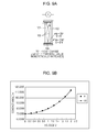
- Fig. 9A is a schematic diagram of the liquid lens of a sixth embodiment (with a cylindrical electrode) according to the present invention.
- Fig. 9B is a V- ⁇ graph.
- Fig. 10A is a schematic diagram of the liquid lens of a seventh embodiment (with a cylindrical electrode) according to the present invention.
- Fig. 10B is a V- ⁇ graph.
- Fig. 11A is a schematic diagram of the liquid lens of an eighth embodiment (with a cylindrical electrode) according to the present invention.
- Fig. 11B is a V- ⁇ graph.
- Fig. 12A is a schematic diagram of the liquid lens of a ninth embodiment (with a cylindrical electrode) according to the present invention.
- Fig. 12B is a V- ⁇ graph.
- Fig. 13A is a schematic diagram of the liquid lens of a tenth embodiment (with a cylindrical electrode) according to the present invention.
- Fig. 13B is a V- ⁇ graph.
- Fig. 14A is a schematic diagram of the liquid lens of an eleventh embodiment (with a cylindrical electrode) according to the present invention.
- Fig. 14B is a V- ⁇ graph.
- Fig. 15A is a schematic diagram of the liquid lens of a twentieth embodiment (with a cylindrical taper electrode) according to the present invention.
- Fig. 15B is a V- ⁇ graph.
- Fig. 16A is a schematic diagram of the liquid lens of a thirteenth embodiment (with a cylindrical taper electrode) according to the present invention.
- Fig. 16B is a V- ⁇ graph.
- Fig. 17A is a schematic diagram of the liquid lens of a fourteenth embodiment (with a cylindrical taper electrode) according to the present invention.
- Fig. 17B is a V- ⁇ graph.
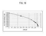
- Fig. 18 is a graph illustrating a relationship between a characteristic of a ⁇ 0 variable layer and reduction in an applied voltage in the embodiment according to the present invention.
- Fig. 19 is a schematic diagram of an optical member in which a liquid lens, a lens and other components are integrated according to the present invention.
- Fig. 20 is a schematic diagram of a camera which incorporates the liquid lens according to the present invention.
- Fig. 21 is a schematic diagram of a main part of a digital camera which incorporates the liquid lens according to the present invention.
- Fig. 22 is a schematic diagram of a main part of a mobile phone which incorporates the liquid lens according to the present invention.
- Fig. 23A is a schematic diagram of a network camera which incorporates the liquid lens according to the present invention.
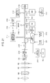
- Fig. 23B is a block diagram of a network camera system.
- Fig. 24A is a schematic diagram of a related art liquid lens (with a cylindrical electrode).
- Fig. 24B is a V- ⁇ graph.
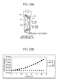
- Fig. 25A is a schematic diagram of a related art liquid lens (with a cylindrical taper electrode).
- Fig. 25B is a V- ⁇ graph.
- Fig. 1 is a schematic sectional view illustrating an example of a liquid lens according to the present invention which incorporates a cylindrical vessel containing a liquid.
- Fig. 1 is taken along a plane which includes a central axis (i.e., an optical axis) of the cylindrical container.
- an insulating layer 103 is provided inside a cylindrical-shaped electrode 104 and forms a vessel which contains a liquid.
- An electrolyte liquid 101 and a non-electrolyte liquid 102 which are mutually immiscible are contained in the vessel.
- the electrolyte liquid 101 and the non-electrolyte liquid 102 have an interface 105 of which end is in contact with an inner wall of the vessel.
- a layer 106 which forms an inner wall of the vessel and has varying affinity with the non-electrolyte liquid depending on the position on the inner wall (hereinafter, referred to as a "variable layer").
- the variable layer 106 has affinity with the non-electrolyte liquid 102 which is relatively low on the side of the non-electrolyte liquid 102 than on the side of the electrolyte liquid 101.
- the electrolyte liquid is an ionizable liquid and that the non-electrolyte liquid is an oil-based liquid, relatively low affinity with the non-electrolyte liquid can be translated as relatively low oleophilicity.
- oleophilicity is relatively high on the side of the electrolyte liquid and relatively low (i.e., oleophobicity is high) on the side of the non-electrolyte liquid.
- a power supply 107 constitutes, together with an electrode 104, a voltage applying unit which applies a voltage to the electrolyte liquid 101.
- a front protection plate 108 and a rear protection plate 109 are constituted by a transparent, light transmissive material.
- a contact angle ⁇ at which an end of the interface between the electrolyte liquid and the non-electrolyte liquid is in contact with the inner wall of the vessel which contains the liquid, and a voltage V applied to the electrolyte liquid
- a contact angle ⁇ at which an end of the interface between the electrolyte liquid and the non-electrolyte liquid is in contact with the inner wall of the vessel which contains the liquid
- a voltage V applied to the electrolyte liquid can be expressed by the following Formula 1, which is called the Young's Formula:
- COS ⁇ COS ⁇ ⁇ 0 - ⁇ / d / ⁇ wo / 2 * V ⁇ 2
- ⁇ 0, ⁇ , d and two are constants and a function with V and ⁇ being variables when the two liquid materials and the insulating layer are determined.
- a sphere radius of curvature of the interface is determined from the diameter of the lens which depends on the size of the vessel containing the liquid lens.
- a focal length is then determined from the radius of curvature and the refractive indices of the two liquids (the refractive power is an inverse of the focal length).
- the present invention is developed focusing on the COS ⁇ 0 component of Formula 1.
- ⁇ 0 is the initial contact angle (applied voltage V- ⁇ ) and is determined depending on a characteristic of a surface of the insulating layer which the end of the interface is in contact with. ⁇ 0 is typically a constant value. However, if ⁇ 0 is changed depending on the position on the surface of the insulating layer on which the contact position of the end of the interface moves, the V- ⁇ characteristic can be changed. Thus sensitivity to a response of the contact angle with respect to the applied voltage can be controlled.
- ⁇ 0 which means changing wettability of the surface of the insulating layer depending on the position
- sensitivity about the V- ⁇ characteristic is increased with varying wettability of the surface of the insulating layer (i.e., the inner wall of the vessel) depending on the position, in particular, letting affinity with the non-electrolyte liquid be relatively low on the side of the non-electrolyte liquid than on the side of the electrolyte liquid.
- the present invention includes a configuration in which not only wettability of the surface of the insulating layer is changed directly, but a thin variable layer with variable wettability is provided on the insulating layer which has a uniform characteristic.
- relatively lowing affinity with the non-electrolyte liquid on the side of the non-electrolyte liquid than on the side of the electrolyte liquid includes letting relative hydrophilicity, hydrophobicity, oleophilicity or oleophobicity differ depending on the position on the surface of the insulating layer which the end of the interface is in contact with (i.e., the vessel inner wall).
- the radius of curvature represented by a solid line i.e., the end A of the interface 105
- the radius of curvature represented by a dotted line i.e., the end C of the interface 105
- Wettability of the variable layer 106 is changed from the side of the electrolyte liquid 101 (point A of Fig. 1 ) to the side of the non-electrolyte liquid 102 (point C of Fig. 1 ) so that affinity (oleophilicity) with the non-electrolyte liquid 102 is lowered (i.e., oleophobicity is increased) .
- the change of the contact angle ⁇ in Fig. 1 from 70 degrees (A) to 110 degrees (C) can be made with low driving voltage and a small voltage change compared with a configuration using a uniform layer with constant wettability (of which detailed description will be given later in the embodiments and comparative embodiments).
- the refractive index of the electrolyte liquid with respect to the D line of the electrolyte liquid (wavelength: 587.6 nm) is 1.4 and with respect to the D line of the non-electrolyte liquid is 1.6.
- a liquid lens illustrated in Fig. 2 includes a tapered cylindrical electrode (with a tapered section) while the liquid lens illustrated in Fig. 1 includes a cylindrical electrode.
- Fig. 2 is a sectional view taken along a plane which includes a central axis (i.e., an optical axis) of a cylindrical container.
- An inner surface (i.e., an insulating layer) of a vessel which an end of an interface of liquids is in contact with is a plane when seen in a sectional view.
- the liquid lens illustrated in Fig. 2 is substantially similar to that illustrated in Fig. 1 except that the tapered cylindrical electrode is used.
- a front protection plate 108 and a rear protection plate 109 are not illustrated in Fig. 2 .
- wettability of a variable layer 106 is changed such that affinity with the non-electrolyte liquid 102 is lowered (i.e., oleophobicity is increased) toward the non-electrolyte liquid 102 (i.e., point C) from the electrolyte liquid 101 (i.e., point A in Fig. 2 ) in the liquid lens of this embodiment.
- the material property of the electrolyte liquid 101, the non-electrolyte liquid 102 and the variable layer 106 affects the interface energy: thus a range of the contact angle used as the liquid lens may vary.
- the liquid lens with the tapered cylindrical electrode illustrated in Fig. 2 is desirably used.
- solid-state members i.e., the insulating layer 103, the electrode 104 and the variable layer 106
- a taper angle a of 30 degrees with respect to the unillustrated optical axis in order to obtain the same change in a radius of curvature (i.e., the same change in the focal length) as that of the liquid lens with the cylindrical electrode illustrated in Fig. 1 .
- the taper angle of 30 degrees can increase the usage range of the contact angle from 40 degrees to 80 degrees and thus can provide a change in the contact angle from 70 degrees to 110 degrees. As a result, the same operation as the liquid lens illustrated in Fig. 1 is achieved.
- a liquid lens illustrated in Fig. 3 is an example which includes a cylindrical electrode with a concave surface.
- the liquid lens illustrated in Fig. 3 is the same as that illustrated in Fig. 1 except for the inclusion of the cylindrical electrode with a concave surface.
- the same change in a radius of curvature R as that of the liquid lens illustrated in Fig. 1 can achieve a further reduction in a contact angle ⁇ with low driving voltage (i.e., the contact angle ⁇ is reduced to 100 degrees from 80 degrees).
- vessels can be used to contain the electrolyte liquid and the non-electrolyte liquid which are mutually immiscible and a cylindrical vessel of which refractive power can be changed from positive to negative or vice versa is especially suitable.
- the vessels include a cylindrical metallic material (e.g., aluminum, copper, iron or alloys thereof) of which inner surface is coated with an insulating layer and a variable layer, and a cylindrical glass or plastic material of which inner surface is coated with an electrically conductive layer, an insulating layer and a variable layer.
- Examples of the electrolyte liquid include salt-containing water.
- the salt may be, for example, a chloride compound or a bromide compound.
- Examples of the non-electrolyte liquid include an oil-based solvent, such as silicone oil, and various organic solvents. Combination of the electrolyte liquid and the non-electrolyte liquid can be determined such that the liquids have different refractive indices and immiscibility with each other; liquids which are equivalent or substantially equivalent in density are especially suitable when considering performance as a lens.
- Examples of the surface of the inner wall of the vessel having varying affinity with the non-electrolyte liquid include: (i) a surface of the inner wall of the vessel coated with an insulating layer, the insulating layer being surface-treated to provide varying affinity depending on the position; (ii) a surface of the inner wall of the vessel coated with an insulating layer and a thin layer, the thin layer being surface-treated to provide varying affinity; and (iii) a surface of the inner wall of the vessel which itself is formed of an insulating material, the inner surface thereof being surface-treated to provide varying affinity depending on the position (the outside of the vessel is coated with a metallic material which constitutes the electrode).
- Examples of the material of the thin layer used to coat the surface include an epoxy-based material, a silane coupling material and a parylene-based material, which are oleophilic materials.
- These materials may be subject to UV irradiation, electron irradiation, corona discharge or ozone irradiation; with such treatments, the materials easily produce OH ions on the surfaces thereof and the characteristic of the surface of the thin layer changes from oleophilic to hydrophilic.
- variable layer according to the present invention becomes relatively oleophobic (i.e., hydrophilic) toward the non-electrolyte liquid from the electrolyte liquid.
- the thin layer becomes highly oleophobic (i.e., hydrophilic) toward the non-electrolyte liquid from the electrolyte liquid.
- Varying affinity depending on the position means varying initial contact angle ⁇ 0 depending on the position. That is, a change in ⁇ 0 depending on the position can be variable by the control of the irradiation amount of energy depending on the position.
- the irradiation amount of energy may also be increased rapidly to enhance sensitivity to oleophobicity.
- a hydrophilic material may be used as the ⁇ 0 variable layer to lower oleophobicity (hydrophilicity) toward the electrolyte liquid from the non-electrolyte liquid.
- the cylindrical vessel is formed of a metallic material which has a function as an electrode and the inner surface of the metallic material is coated with the insulating layer and the variable layer which constitute the inner wall of the vessel, the following configuration may be provided. That is, after the thin layer is formed on the insulating layer, the surface of the thin layer is covered with a shield, the shield being moved in response to the irradiation time of the energy line to provide the inner wall of the variable layer with varying affinity.
- the cylindrical vessel is formed of a nonconductive plastic or glass material
- the insulating layer and the variable layer are formed after an electrode material (e.g., aluminum, ITO and Ag) is coated.
- the layers may be formed by, for example, vapor deposition or sputtering.
- the inner wall of the vessel may have varying affinity in the direction of the optical axis of the liquid lens.
- sensitivity to a change in the refractive power can be enhanced with low driving voltage and a small voltage change in both the cylindrical taper electrode and the cylindrical electrode.
- the central axis and the optical axis of each of the cylindrical electrodes can be coincident with each other. If these axes are not coincident, the interface has an imperfect spherical surface shape which leads to insufficient optical performance.
- a zoom lens as a combination product of the liquid lens according to at least one embodiment described herein and a common lens, such as a glass lens and a plastic lens.
- the zoom lens can use the varying refractive power of the liquid lens for focusing or zooming.
- no boost circuit to boost the voltage is necessary and thus the power supply of a camera can be used to drive the liquid lens.
- the electrowetting liquid lens operates with low power consumption because the interface is moved by a capacitor effect of the applied voltage and thus substantially no electric current flows therethrough.
- the electrowetting liquid lens requires no focusing mechanism and thereby achieves rapid and silent autofocusing. It is also possible to use the varying refractive power of the liquid lens to change magnification by zooming. In this case, since a zooming mechanism becomes unnecessary or simplified, rapid and silent zooming is achieved in addition to the focusing.
- Enhanced sensitivity to the refractive power with low driving voltage and a small voltage change in the liquid lens disclosed herein contributes to an increase in the response speed of the liquid lens.
- the liquid lens according to any embodiment disclosed herein can be driven by a direct current voltage although an alternating voltage is suitable.
- the lower the driving voltage in the alternating current the smaller the electromagnetic wave noise can be.
- an image pickup element incorporated in a digital camera is easily subject to an influence of the electromagnetic wave noise; thus the low voltage contributes also to noise reduction.
- Fig. 4A is a configuration diagram of the liquid lens according to the first embodiment (with a cylindrical electrode) and Fig. 4B is a V- ⁇ characteristic graph.
- a V- ⁇ characteristic table is given in Table 1.
- Wettability of the ⁇ 0 variable layer 106 when the end of the interface 105 is situated closest to the non-electrolyte liquid 102 is increased to as large as 87 degrees (i.e., oleophobicity is increased). Wettability of the ⁇ 0 variable layer 106 is changed linearly from 70 degrees to 87 degrees as represented by a ⁇ 0 curve in Fig. 4B .
- Fig. 24A is a configuration diagram of a related art liquid lens which incorporates a uniform layer with uniform ⁇ 0 (" ⁇ 0 uniform layer").
- Fig. 24B is a V- ⁇ characteristic graph.
- a V- ⁇ characteristic table of the first comparative embodiment is given in Table 2.
- the graph of Fig. 24B represents a ⁇ curve from 70 degrees to 112 degrees.
- the ⁇ 0 curve indicates that there is no change in ⁇ 0.
- the thickness and the dielectric constant of the insulating layer 103 and the interface energy between the two liquids are the same as those of the first embodiment.
- the largest contact angle is set to ⁇ max (on the side of the non-electrolyte liquid 102) and the initial contact angle under no voltage application representing wettability of the layer at the point (i.e., the ⁇ 0 variable layer 106) is set to ⁇ 0max.
- Fig. 5A is a configuration diagram of the liquid lens according to the second embodiment (with a cylindrical electrode) and Fig. 5B is a V- ⁇ characteristic graph.
- a V- ⁇ characteristic table is given in Table 3.
- the thickness of the insulating layer 103 below the ⁇ 0 variable layer 106, the dielectric constant of the insulating layer 103 and the interface energy ⁇ wo between the two liquids are the same as those of the first embodiment.
- ⁇ 0 uniform layer An example of a related art layer with uniform ⁇ 0 (“ ⁇ 0 uniform layer") is illustrated in Figs. 24A and 24B .
- the amount of voltage change is reduced and thereby the liquid lens according to the second embodiment can be driven with a voltage of 7.5V that is smaller than half that of the related art ⁇ 0 uniform layer is used.
- Fig. 6A is a configuration diagram of the liquid lens according to the third embodiment (with a cylindrical electrode) and Fig. 6B is a V- ⁇ characteristic graph.
- a V- ⁇ characteristic table is given in Table 4.
- the thickness of the insulating layer 103 below the ⁇ 0 variable layer 106, the dielectric constant of the insulating layer 103 and the interface energy ⁇ wo between the two liquids are the same as those of the first embodiment.
- ⁇ 0 uniform layer An example of a related art layer with uniform ⁇ 0 (“ ⁇ 0 uniform layer”) is illustrated in Figs. 24A and 24B .
- a change in ⁇ 0 i.e., a change in wettability
- ⁇ 0 in each position and the actual contact angle ⁇ when voltage is applied is close to each other.
- substantially no voltage change is necessary. It is therefore recognized that a change in power (from ⁇ : 70 degrees to ⁇ : 115 degrees) is achieved with a driving voltage of as small as 1.5V.
- Fig. 7A is a configuration diagram of the liquid lens according to the fourth embodiment (with a cylindrical electrode) and Fig. 7B is a V- ⁇ characteristic graph.
- a V- ⁇ characteristic table is given in Table 5.
- a change in wettability of the ⁇ 0 variable layer 106 differential monotonically increases from 70 degrees to 88.5 degrees as represented by a ⁇ 0 curve in Fig. 7B .
- the thickness of the insulating layer 103 below the ⁇ 0 variable layer 106, the dielectric constant of the insulating layer 103 and the interface energy ⁇ wo between the two liquids are the same as those of the first embodiment.
- ⁇ 0 uniform layer An example of a related art layer with uniform ⁇ 0 (“ ⁇ 0 uniform layer”) is illustrated in Figs. 24A and 24B .
- a characteristic change in the ⁇ 0 variable layer 106 is high on the high voltage side (i.e., the side of the non-electrolyte liquid) and thus V- ⁇ sensitivity at low voltage regions is low.
- Fig. 8A is a configuration diagram of the liquid lens according to the fifth embodiment (with a cylindrical electrode) and Fig. 8B is a V- ⁇ characteristic graph.
- a V- ⁇ characteristic table is given in Table 6.
- a change in wettability of the ⁇ 0 variable layer 106 differential monotonically increases from 70 degrees to 107 degrees as represented by a ⁇ 0 curve in Fig. 8B .
- the thickness of the insulating layer 103 below the ⁇ 0 variable layer 106, the dielectric constant of the insulating layer 103 and the interface energy ⁇ wo between the two liquids are the same as those of the first embodiment.
- ⁇ 0 uniform layer An example of a related art layer with uniform ⁇ 0 (“ ⁇ 0 uniform layer”) is illustrated in Figs. 24A and 24B .
- Fig. 9A is a configuration diagram of the liquid lens according to the sixth embodiment (with a cylindrical electrode) and Fig. 9B is a V- ⁇ characteristic graph.
- a V- ⁇ characteristic table is given in Table 7.
- a change in wettability of the ⁇ 0 variable layer 106 differential monotonically increases from 70 degrees to 113.6 degrees as represented by a ⁇ 0 curve in Fig. 9B .
- the thickness of the insulating layer 103 below the ⁇ 0 variable layer 106, the dielectric constant of the insulating layer 103 and the interface energy ⁇ wo between the two liquids are the same as those of the first embodiment.
- ⁇ 0 uniform layer An example of a related art layer with uniform ⁇ 0 (“ ⁇ 0 uniform layer”) is illustrated in Figs. 24A and 24B .
- the fourth to sixth embodiments have wettability of the ⁇ 0 variable layer 106 which differential monotonically increases while the first to third embodiments have wettability which changes linearly.
- a linear change is generally suitable because V- ⁇ sensitivity increases by about 80 percent of a range of the driving voltage.
- Fig. 10A is a configuration diagram of the liquid lens according to the seventh embodiment (with a cylindrical electrode) and Fig. 10B is a V- ⁇ characteristic graph.
- a V- ⁇ characteristic table is given in Table 8.
- a change in wettability of the ⁇ 0 variable layer 106 differential monotonically decreases from 70 degrees to 87.5 degrees as represented by a ⁇ 0 curve in Fig. 10B .
- the thickness of the insulating layer 103 below the ⁇ 0 variable layer 106, the dielectric constant of the insulating layer 103 and the interface energy ⁇ wo between the two liquids are the same as those of the first embodiment.
- ⁇ 0 uniform layer An example of a related art layer with uniform ⁇ 0 (“ ⁇ 0 uniform layer”) is illustrated in Figs. 24A and 24B .
- Fig. 11A is a configuration diagram of the liquid lens according to the eighth embodiment (with a cylindrical electrode) and Fig. 11B is a V- ⁇ characteristic graph.
- a V- ⁇ characteristic table is given in Table 9.
- a change in wettability of the ⁇ 0 variable layer 106 differential monotonically increases from 70 degrees to 107.1 degrees as represented by a ⁇ 0 curve in Fig. 11B .
- the thickness of the insulating layer 103 below the ⁇ 0 variable layer 106, the dielectric constant of the insulating layer 103 and the interface energy ⁇ wo between the two liquids are the same as those of the first embodiment.
- ⁇ 0 uniform layer An example of a related art layer with uniform ⁇ 0 (“ ⁇ 0 uniform layer”) is illustrated in Figs. 24A and 24B .
- Fig. 12A is a configuration diagram of the liquid lens according to the ninth embodiment (with a cylindrical electrode) and Fig. 12B is a V- ⁇ characteristic graph.
- a V- ⁇ characteristic table is given in Table 10.
- the thickness of the insulating layer 103 below the ⁇ 0 variable layer 106, the dielectric constant of the insulating layer 103 and the interface energy ⁇ wo between the two liquids are the same as those of the first embodiment.
- ⁇ 0 uniform layer An example of a related art layer with uniform ⁇ 0 (“ ⁇ 0 uniform layer”) is illustrated in Figs. 24A and 24B .
- the seventh to ninth embodiments have wettability of the ⁇ 0 variable layer 106 which differential monotonically decreases while the first to third embodiments have wettability which changes linearly.
- the seventh to ninth embodiments have higher V- ⁇ sensitivity than those embodiments with linearly changing wettability.
- V- ⁇ sensitivity the differential monotonical decrease is the highest, the differential monotonical increase is the lowest and the linear change is therebetween; among these, the differential monotonical decrease is the most suitable.
- Fig. 13A is a configuration diagram of the liquid lens according to the tenth embodiment (with a cylindrical electrode) and Fig. 13B is a V- ⁇ characteristic graph.
- a V- ⁇ characteristic table is given in Table 11.
- sensitivity to the change in wettability of the ⁇ 0 variable layer 106 is low in a low voltage region and a high voltage region and high in a middle voltage region.
- a lens unit is formed as a combination of a liquid lens and a common lens (i.e., a lens made of solid material, such as glass, plastic, quartz or the like) and the liquid lens is used for focusing or zooming, optical performance of the entire lens unit is hardly affected when the liquid lens has the refractive power about "0" even if V- ⁇ varies due to an error.
- a common lens i.e., a lens made of solid material, such as glass, plastic, quartz or the like
- the negative power of the liquid lens becomes the largest when the contact angle ⁇ is 70 degrees (an interface at this time is represented by a solid line), the refractive power of the liquid lens is "0" when the contact angle ⁇ is 90 degrees and the positive power of the liquid lens becomes the largest when the contact angle ⁇ is 110 degrees (an interface at this time is represented by a dotted line).
- a minute change in the voltage V applied by the voltage applying unit is set to dV in the vicinity of regions where the refractive power is "0" when the contact angle ⁇ is 90 degrees (i.e., the contact angle ⁇ is within ⁇ 7 degrees) and a minute change in this ⁇ 0 when the contact angle on the side of the non-electrolyte liquid between the interface and the inner wall which are in contact with each other which are in contact with each other is ⁇ 0 under no voltage application is set to d ⁇ 0.
- d ⁇ 0/dv i.e., the differential absolute value
- Fig. 14A is a configuration diagram of the liquid lens according to the eleventh embodiment (with a cylindrical electrode) and Fig. 14B is a V- ⁇ characteristic graph.
- a V- ⁇ characteristic table (C) is given in Table 12.
- sensitivity to the change in wettability of the ⁇ 0 variable layer 106 is low in a low voltage region and a high voltage region and high in a middle voltage region.
- ⁇ 0 uniform layer a voltage V is changed from 0V to 18V and the contact angle ⁇ is changed from 70 degrees to 110.1 degrees ( ⁇ 0 is always 70 degrees).
- the ⁇ 0 variable layer is provided with a characteristic such that sensitivity to the change in wettability increases linearly (i.e., the rate of change in oleophobicity is high) in the vicinity of regions where the refractive power is "0" when the contact angle ⁇ is 90 degrees (i.e., the contact angle ⁇ is within ⁇ 7 degrees) and a minute change in the voltage V applied by the voltage applying unit is set to dV, and a minute change in this ⁇ 0 when the contact angle on the side of the non-electrolyte liquid between the interface and the inner wall which are in contact with each other is ⁇ 0 under no voltage application is set to d ⁇ 0. Under this condition, d ⁇ 0/dV (i.e., the differential absolute value) becomes the maximum and V- ⁇ sensitivity is enhanced and varied largely to increase the speed.
- d ⁇ 0/dV i.e., the differential absolute value
- the ⁇ 0 variable layer is provided with a characteristic such that sensitivity to the change in wettability decreases linearly (i.e., the rate of change in oleophobicity is low) in the vicinity of regions where the contact angle ⁇ is 70 degrees and 110 degrees (i.e., the contact angle ⁇ is within ⁇ 7 degrees) where the power is high, a minute change in the voltage V applied by the voltage applying unit is set to dV, and a minute change in this ⁇ 0 when the contact angle on the side of the non-electrolyte liquid between the interface and the inner wall which are in contact with each other is ⁇ 0 under no voltage application is set to d ⁇ 0. Under this condition, d ⁇ 0/dV (i.e., the differential absolute value) becomes the minimum. V- ⁇ sensitivity is decreased to be varied slightly and V- ⁇ is controlled highly accurately, thus the quality of lens is enhanced.
- the ⁇ 0 line in Fig. 14B represents a linear change in three regions (i.e., an inclination is greater in the vicinity of the region with the refractive power of 0 and is smaller in other regions). It is therefore possible to manufacture the ⁇ 0 variable layer in an easier manner than that in the tenth embodiment which has a continuous curve.
- Fig. 15A is a configuration diagram of the liquid lens according to the twelfth embodiment (with a cylindrical taper electrode) and Fig. 15B is a V- ⁇ characteristic graph.
- a V- ⁇ characteristic table is given in Table 13.
- the taper angle ⁇ is 30 degrees.
- Wettability of the ⁇ 0 variable layer 106 is changed linearly from 40 degrees to 72 degrees as represented by the ⁇ 0 curve in Fig. 15B (see the ⁇ 0 curve of the graph in Fig. 15B ).
- Figs. 25A and 25B illustrate a liquid lens of the second comparative embodiment which incorporates a related art ⁇ 0 uniform layer with uniform ⁇ 0 in place of the ⁇ 0 variable layer 106 for comparison with the cylindrical taper electrode.
- Fig. 25A is a configuration diagram and Fig. 25B is a V- ⁇ characteristic graph.
- a V- ⁇ characteristic table of the second comparative embodiment is given in Table 14.
- the graph of Fig. 25B represents a ⁇ curve from 40 degrees to 80.9 degrees. The ⁇ 0 curve indicates that there is no change in ⁇ 0.
- the taper angle, the thickness and the dielectric constant of the insulating layer 103 and the interface energy between the two liquids are the same as those of the twelfth embodiment of the present embodiment.
- Fig. 16A is a configuration diagram of the liquid lens according to the thirteenth embodiment (with a cylindrical taper electrode) and Fig. 16B is a V- ⁇ characteristic graph.
- a V- ⁇ characteristic table (C) is given in Table 15.
- the taper angle ⁇ is 30 degrees which is the same in the twelfth embodiment.
- the range of the change in wettability of the ⁇ 0 variable layer 106 is 40 degrees to 81 degrees as represented by the ⁇ 0 curve of the graph in Fig. 16B , sensitivity to the change in wettability is low in a low voltage region and a high voltage region and high in a middle voltage region.
- the thickness of the insulating layer 103 below the ⁇ 0 variable layer 106, the dielectric constant of the insulating layer 103 and the interface energy between the two liquids are the same as those of the twelfth embodiment.
- ⁇ 0 uniform layer An example of a related art layer with uniform ⁇ 0 (" ⁇ 0 uniform layer") with a cylindrical taper electrode is illustrated in Figs. 25A and 25B .
- the characteristic of the change in wettability is represented by a line (see graph in Fig. 16B ).
- the ⁇ 0 variable layer is provided with a characteristic such that sensitivity to the change in wettability increases linearly (i.e., the rate of change in oleophobicity is high) in the vicinity of regions where the power is "0" (i.e., the contact angle ⁇ is within ⁇ 7 degrees) when the contact angle ⁇ is 60 degrees a minute change in the voltage V applied by the voltage applying unit is set to dV, and a minute change in this ⁇ 0 when the contact angle on the side of the non-electrolyte liquid between the interface and the inner wall which are in contact with each other is ⁇ 0 under no voltage application is set to d ⁇ 0. Under this condition, d ⁇ 0/dV (i.e., the differential absolute value) becomes the maximum and V- ⁇ sensitivity is enhanced and varied largely to increase the speed.
- d ⁇ 0/dV i.e., the differential absolute value
- the ⁇ 0 variable layer is provided with a characteristic such that sensitivity to the change in wettability decreases linearly (i.e., the rate of change in oleophobicity is low) in the vicinity of regions where the contact angle ⁇ is 40 degrees and 82 degrees (i.e., the contact angle ⁇ is within ⁇ 7 degrees) where the power is high.
- a minute change in the voltage V applied by the voltage applying unit is set to dV, and a minute change in this ⁇ 0 when the contact angle on the side of the non-electrolyte liquid between the interface and the inner wall which are in contact with each other is ⁇ 0 under no voltage application is set to d ⁇ 0 Under this condition, d ⁇ 0/dV (i.e., the differential absolute value) becomes the minimum.
- V- ⁇ sensitivity is decreased to be varied slightly and V- ⁇ is controlled highly accurately, thus the quality of lens is enhanced.
- the ⁇ 0 line in Fig. 16B represents a linear change in three regions (i.e., an inclination is greater in the vicinity of the region with the refractive power of 0 and is smaller in other regions). It is therefore possible to manufacture the ⁇ 0 variable layer in an easier manner than that in the tenth embodiment which has a continuous curve.
- Fig. 17A is a configuration diagram of the liquid lens according to the fourteenth embodiment (with a cylindrical taper electrode) and Fig. 17B is a V- ⁇ characteristic graph.
- a V- ⁇ characteristic table is given in Table 16.
- the taper angle ⁇ is 30 degrees which is the same in the twelfth embodiment.
- the range of the change in wettability of the ⁇ 0 variable layer 106 is 40 degrees to 80 degrees as represented by the ⁇ 0 curve of the graph in Fig. 17B .
- the thickness of the insulating layer 103 below the ⁇ 0 variable layer 106, the dielectric constant of the insulating layer 103 and the interface energy between the two liquids are the same as those of the twelfth and thirteenth embodiments.
- ⁇ 0 uniform layer An example of a related art layer with uniform ⁇ 0 (" ⁇ 0 uniform layer") with a cylindrical taper electrode is illustrated in Figs. 25A and 25B .
- the characteristic of the change in wettability is represented by a line (see graph in Fig. 17B ).
- the ⁇ 0 variable layer is provided with a characteristic such that sensitivity to the change in wettability increases linearly (i.e., the rate of change in oleophobicity is high) in the vicinity of regions where the power is "0" (i.e., the contact angle ⁇ is within ⁇ 7 degrees) when the contact angle ⁇ is 60 degrees, a minute change in the voltage V applied by the voltage applying unit is set to dV, and a minute change in this ⁇ 0 when the contact angle on the side of the non-electrolyte liquid between the interface and the inner wall which are in contact with each other is ⁇ 0 under no voltage application is set to d ⁇ 0. Under this condition, d ⁇ 0/dV (i.e., the differential absolute value) becomes the maximum and V- ⁇ sensitivity is enhanced and varied largely to increase the speed.
- d ⁇ 0/dV i.e., the differential absolute value
- a related art ⁇ 0 uniform layer with no sensitivity to the change in wettability is used in the vicinity of regions where the contact angle ⁇ is 40 degrees and 80.9 degrees (i.e., within the contact angle ⁇ ⁇ 7 degrees) where the power is high, a minute change in the voltage V applied by the voltage applying unit is set to dV, and a minute change in this ⁇ 0 when the contact angle on the side of the non-electrolyte liquid between the interface and the inner wall which are in contact with each other is ⁇ 0 under no voltage application is set to d ⁇ 0. Under this condition, d ⁇ 0/dV (i.e., the differential absolute value) becomes the minimum and the V- ⁇ sensitivity is significantly reduced. This is effective when fine ⁇ control around this region is necessary. Since the line has three regions and both end regions are ⁇ 0 uniform layers, the liquid lens is manufactured further easily.
- ⁇ max i.e., the maximum value of the contact angle
- the contact angle under no voltage application representing wettability of the layer at the point i.e., the ⁇ 0 variable layer 106
- ⁇ max is a value of the highest applied voltage and the end of the interface has been moved to a position closest to the non-electrolyte liquid.
- Vh is a value of the driving voltage when the ⁇ 0 variable layer is used and the contact angle ⁇ is ⁇ max.
- Vk is a value of the driving voltage when the related art ⁇ 0 uniform layer is used and the contact angle ⁇ is ⁇ max.
- Liquid lenses with the characteristic described above can be driven with a driving voltage of about 5V or smaller and thus are suitable to be mounted on mobile equipment.
- Liquid lenses with the characteristic described above can operate with a low voltage.
- Liquid lenses with the characteristic described above can be driven with a driving voltage of about 2V or smaller and thus are suitable to be mounted on mobile equipment and low voltage driving equipment.
- liquid lens according to the present invention is used in an integrated manner with other optical members and semiconductor members will be described.
- Fig. 19 illustrates an example of an optical member in which a liquid lens 150 according to an embodiment of the present invention, a conventional lens 160 (i.e., a lens made of solid material, such as glass, plastic, quartz or the like), and an image pickup element 170, such as a complementary metal-oxide semiconductor (CMOS) sensor and a charged-coupled device (CCD) element, are integrated together using support members 181, 182 and 183.
- CMOS complementary metal-oxide semiconductor
- CCD charged-coupled device
- a plurality of lenses 160 may also be used and various other forms are possible in which, for example, the lens 160 and the liquid lens 150 are situated in an inverted position and the liquid lens 150 is sandwiched between the lenses 160.
- three components, namely the liquid lens 150, the lens 160 and the image pickup element 170 are integrated together in Fig. 19 , it is also possible that only the liquid lens 150 and the lens 160 are integrated together, or a liquid lens 150, which does not require any lens, and an image pickup element 170 are integrated together.
- the liquid lens 150 and the support member 181 together and incorporate the integrated product on the front side of a camera unit which is constituted by a lens 160 and an image pickup element 170.
- the liquid lens can be made compact: the liquid lens can be integrated with members having other functions to provide a compact product having a plurality of functions.
- the liquid lens can be applied to digital cameras, camera-equipped mobile phones, network cameras such as monitoring cameras and optical members, such as projectors.
- Fig. 20 is a schematic diagram illustrating an exterior of a digital camera to which the liquid lens according to at least one embodiment of the present invention is applied.
- the digital camera includes a photographic lens 201, a viewfinder 202, a flash light emitting unit 203 and a shutter switch 204.
- Fig. 21 is a block diagram of a main part of the digital camera illustrated in Fig. 20 .
- the digital camera illustrated in Fig. 21 incorporates the liquid lens 150 in combination with the conventional lens 160.
- Light passed through the lens 160 and the liquid lens 150 forms an image on the image pickup element 170 via an aperture 163 and a shutter 162.
- the liquid lens 150, the aperture 163 and the shutter 162 are controlled by control signals from the camera control unit 2102.
- the digital camera according to the present embodiment can drive the liquid lens with a low voltage and adverse effects of noise on the image pickup element 170 can be reduced; thus excellent images can be recorded.
- a signal processing unit 2104 performs analog signal processing.
- An A/D converter 2105 converts analog signals into digital signals.
- Image memory 2106 stores the digital signals.
- An image processing unit 2107 performs, for example, signal transformation and signal correction.
- a main CPU 2108 controls all the operations of the digital camera.
- a CPU 2108 controls, for example, the image processing unit 2107 and a camera control unit 2102 through an execution of a control program stored in a ROM 2109.
- a RAM 2110 provides a workspace for the execution of the program.
- Image memory 2111 stores photographed images to be displayed on a pixel display unit 2112.
- a compression and expansion process unit 2117 encodes image information in the image memory 2106.
- the encoded data is stored in the memory card 2119 via an I/F 2118.
- the camera control unit 2102 executes various operations in response to manipulation signals from the operation switch 2113.
- the camera control unit 2102 sends signals to a lighting control unit 2115, which then performs predetermined operations, such as turning a flash 203 on.
- liquid lens according to an embodiment of the present invention is applied to a photographic lens of a camera-equipped mobile phone.
- Fig. 22 is a schematic diagram illustrating a main part of a mobile phone which incorporates the liquid lens according to the present invention.
- a liquid lens 150 according to the present invention is used in a photographic lens unit 2210 of a camera 2234 and images are focused on an image pickup element 170, such as a CCD.
- the liquid lens according to the present invention can be driven with a low voltage and can be made compact: this is advantageous for users of the mobile phone, which is required to be compact and lightweight, because the users can save the inconvenience of frequent battery charge.
- the camera-equipped mobile phone includes: a control unit 2240 which includes a CPU 2241 and a ROM 2242; an antenna 2231 and a radio unit 2232, which are connected to the control unit 2240; a microphone 2233, a receiver 2235 and an image storage unit 2236, in which images photographed with the camera 2234 are stored; and an operation key 2237, a display unit 2238, such as an LCD, and a shutter key 2239 used in the photographing with the camera.
- a control unit 2240 which includes a CPU 2241 and a ROM 2242; an antenna 2231 and a radio unit 2232, which are connected to the control unit 2240; a microphone 2233, a receiver 2235 and an image storage unit 2236, in which images photographed with the camera 2234 are stored; and an operation key 2237, a display unit 2238, such as an LCD, and a shutter key 2239 used in the photographing with the camera.
- Fig. 23A is a schematic diagram of an exterior of the network camera which incorporates the liquid lens according to the present invention.
- Fig. 23B is a block circuit diagram of a network camera system.
- a lens unit 2301, a camera platform unit 2302 and a cover which covers the lens unit 2301 are illustrated in Fig. 23A .
- the liquid lens 150 according to the present invention is incorporated as one of the lenses which constitute the lens unit 2301.
- Fig. 23A is a schematic diagram of an exterior of the network camera which incorporates the liquid lens according to the present invention.
- Fig. 23B is a block circuit diagram of a network camera system.
- a lens unit 2301, a camera platform unit 2302 and a cover which covers the lens unit 2301 are illustrated in Fig. 23A .
- the liquid lens 150 according to the present invention is incorporated as one of the lenses which constitute the lens unit 2301.
- a lens unit 160, a liquid lens 150 and an image pickup element 170 are arranged along an optical axis and outputs of the image pickup element 170 are connected to an image processing circuit 2315 and a focus processing circuit 2316 via an amplifier 2314.
- a panning direction driving motor 2321 and a tilt direction driving motor 2322 for driving the lens unit 2301 are provided in the camera platform unit 2302.
- An output of the image processing circuit 2315 is connected to a network processing circuit 2323 in the camera platform unit 2302 and an output of the focus processing circuit 2316 is connected to a CPU 2324.
- An output of the CPU 2324 is connected to an external LAN 2331 via the network processing circuit 2323 and a personal computer 2332 is connected to the LAN 2331.
- Outputs of the CPU 2324 are connected to driving motors 2321 and 2322 via a pan-driving circuit 2325 and a tilt-driving circuit 2326 to supply driving signals to these circuits.
- the CPU 2324 is also connected to a liquid lens driving circuit 2317.
- the liquid lens 150 is driven by the liquid lens driving circuit 2317 and controls the focusing.
- the network camera according to the present embodiment can also be made compact.
- the network camera according to the present embodiment can photograph remote images with the network camera which itself can be hidden: thus the network camera can be used as, for example, a monitoring camera and as a security camera for covertly taking live images in leisure venues.
- a liquid lens includes a vessel having an inner wall and configured to contain liquid, an electrolyte liquid (101) and a non-electrolyte liquid (102) forming an interface (105) therebetween and being contained in the vessel, and a voltage applying unit which applies a voltage (V) to the electrolyte liquid (101).
- V voltage
- a shape of the interface (105) between the electrolyte liquid (101) and the non-electrolyte liquid (102) is changed by application of the voltage (V).
- the inner wall of the vessel has varying affinity with the non-electrolyte liquid (102) depending on a position on the inner wall where an end of the interface (105) contacts the inner wall; and the affinity on the side of the inner wall where the non-electrolyte liquid (102) is situated is lower than the affinity on the side of the inner wall where the electrolyte liquid (101) is situated.
Landscapes
- Physics & Mathematics (AREA)
- General Physics & Mathematics (AREA)
- Optics & Photonics (AREA)
- Mechanical Light Control Or Optical Switches (AREA)
- Automatic Focus Adjustment (AREA)
Applications Claiming Priority (1)
| Application Number | Priority Date | Filing Date | Title |
|---|---|---|---|
| JP2010188655 | 2010-08-25 |
Publications (1)
| Publication Number | Publication Date |
|---|---|
| EP2423715A1 true EP2423715A1 (de) | 2012-02-29 |
Family
ID=44719231
Family Applications (1)
| Application Number | Title | Priority Date | Filing Date |
|---|---|---|---|
| EP11176664A Withdrawn EP2423715A1 (de) | 2010-08-25 | 2011-08-05 | Flüssiglinse und Vorrichtung damit |
Country Status (4)
| Country | Link |
|---|---|
| US (1) | US8373931B2 (de) |
| EP (1) | EP2423715A1 (de) |
| JP (1) | JP6004618B2 (de) |
| CN (1) | CN102385077B (de) |
Cited By (1)
| Publication number | Priority date | Publication date | Assignee | Title |
|---|---|---|---|---|
| CN116719108A (zh) * | 2023-06-08 | 2023-09-08 | 西安电子科技大学 | 一种基于超疏油-亲油表面的无极变焦太赫兹液体透镜的制备方法 |
Families Citing this family (11)
| Publication number | Priority date | Publication date | Assignee | Title |
|---|---|---|---|---|
| US8355209B2 (en) * | 2009-12-25 | 2013-01-15 | Canon Kabushiki Kaisha | Liquid lens |
| US10598919B2 (en) * | 2016-03-04 | 2020-03-24 | The Regents Of The University Of Colorado | Electrowetting-actuated optical shutters |
| US10072822B2 (en) * | 2016-06-21 | 2018-09-11 | Abl Ip Holding Llc | Variable total internal reflection electrowetting lens assembly |
| US9977235B2 (en) | 2016-06-21 | 2018-05-22 | Abl Ip Holding Llc | Variable total internal reflection electrowetting lens assembly for a detector |
| US10247935B2 (en) | 2016-07-06 | 2019-04-02 | Abl Ip Holding Llc | MicroLED with integrated controllable beam steering and/or shaping |
| KR20180088204A (ko) * | 2017-01-26 | 2018-08-03 | 엘지이노텍 주식회사 | 액체렌즈 및 이를 포함하는 카메라 모듈 및 광학기기 |
| KR102725878B1 (ko) * | 2017-02-24 | 2024-11-04 | 엘지이노텍 주식회사 | 액체 렌즈, 카메라 모듈 및 광학기기 |
| US11191636B2 (en) * | 2017-08-22 | 2021-12-07 | Verily Life Sciences Llc | Electrowetting lenses having oleophobic surfaces |
| CN107507582B (zh) * | 2017-10-18 | 2019-06-07 | 福州大学 | 一种调整电润湿显示器驱动波形的方法 |
| CN107688243A (zh) * | 2017-10-20 | 2018-02-13 | 上海天马微电子有限公司 | 一种显示装置 |
| CN117072914A (zh) * | 2023-08-22 | 2023-11-17 | 上海燧影光电科技有限公司 | 基于液体透镜阵列的照明装置、控制方法、终端及介质 |
Citations (5)
| Publication number | Priority date | Publication date | Assignee | Title |
|---|---|---|---|---|
| FR2769375A1 (fr) * | 1997-10-08 | 1999-04-09 | Univ Joseph Fourier | Lentille a focale variable |
| WO2004102250A1 (en) * | 2003-05-14 | 2004-11-25 | Koninklijke Philips Electronics N.V. | Variable lens |
| EP1701195A1 (de) * | 2005-03-08 | 2006-09-13 | Sony Corporation | Optische elektrobenetzende Vorrichtung |
| WO2007049280A1 (en) * | 2005-10-26 | 2007-05-03 | Ramot At Tel-Aviv University Ltd | Method and device for wettability modification of materials |
| JP2007293349A (ja) | 2006-04-25 | 2007-11-08 | Samsung Electro-Mechanics Co Ltd | 曲面の接触面を有する液体レンズ |
Family Cites Families (9)
| Publication number | Priority date | Publication date | Assignee | Title |
|---|---|---|---|---|
| JP4312319B2 (ja) * | 1999-11-10 | 2009-08-12 | 大日本印刷株式会社 | マイクロレンズ基板およびその製造法 |
| JP2007121846A (ja) * | 2005-10-31 | 2007-05-17 | Konica Minolta Opto Inc | 液体レンズ装置、振れ補正装置及び撮像装置 |
| KR100723244B1 (ko) * | 2005-12-27 | 2007-05-29 | 삼성전기주식회사 | 전기습윤을 이용한 액체렌즈 제조방법 및 이에 의한액체렌즈 |
| US20100309560A1 (en) * | 2006-02-24 | 2010-12-09 | Agency For Science, Technology And Research | Method for Forming Variable Focus Liquid Lenses in a Tubular Housing |
| TWI315321B (en) * | 2006-03-16 | 2009-10-01 | Chunghwa Picture Tubes Ltd | Optical components array device, lens array and fabrication method thereof |
| JP2008197296A (ja) * | 2007-02-13 | 2008-08-28 | Sony Corp | エレクトロウェッティングデバイス及びその製造方法 |
| JP2010079096A (ja) * | 2008-09-26 | 2010-04-08 | Sony Corp | 光学素子及び撮像装置 |
| JP2010107908A (ja) * | 2008-10-31 | 2010-05-13 | Sony Corp | エレクトロウェッティング装置、可変焦点レンズ、光ピックアップ装置、光記録再生装置、液滴操作装置、光学素子、ズームレンズ、撮像装置、光変調装置、表示装置、ストロボ装置及びエレクトロウェッティング装置の駆動方法 |
| JP2010256511A (ja) * | 2009-04-23 | 2010-11-11 | Sony Corp | 光学装置、電子機器、光学装置の製造方法 |
-
2011
- 2011-08-05 EP EP11176664A patent/EP2423715A1/de not_active Withdrawn
- 2011-08-10 US US13/206,674 patent/US8373931B2/en not_active Expired - Fee Related
- 2011-08-22 CN CN201110240684.9A patent/CN102385077B/zh not_active Expired - Fee Related
- 2011-08-22 JP JP2011180364A patent/JP6004618B2/ja not_active Expired - Fee Related
Patent Citations (6)
| Publication number | Priority date | Publication date | Assignee | Title |
|---|---|---|---|---|
| FR2769375A1 (fr) * | 1997-10-08 | 1999-04-09 | Univ Joseph Fourier | Lentille a focale variable |
| JP2001519539A (ja) | 1997-10-08 | 2001-10-23 | ユニヴェルシテ ジョセフ フーリエ | 可変焦点レンズ |
| WO2004102250A1 (en) * | 2003-05-14 | 2004-11-25 | Koninklijke Philips Electronics N.V. | Variable lens |
| EP1701195A1 (de) * | 2005-03-08 | 2006-09-13 | Sony Corporation | Optische elektrobenetzende Vorrichtung |
| WO2007049280A1 (en) * | 2005-10-26 | 2007-05-03 | Ramot At Tel-Aviv University Ltd | Method and device for wettability modification of materials |
| JP2007293349A (ja) | 2006-04-25 | 2007-11-08 | Samsung Electro-Mechanics Co Ltd | 曲面の接触面を有する液体レンズ |
Cited By (1)
| Publication number | Priority date | Publication date | Assignee | Title |
|---|---|---|---|---|
| CN116719108A (zh) * | 2023-06-08 | 2023-09-08 | 西安电子科技大学 | 一种基于超疏油-亲油表面的无极变焦太赫兹液体透镜的制备方法 |
Also Published As
| Publication number | Publication date |
|---|---|
| JP2012068624A (ja) | 2012-04-05 |
| JP6004618B2 (ja) | 2016-10-12 |
| CN102385077B (zh) | 2014-08-13 |
| US20120050881A1 (en) | 2012-03-01 |
| US8373931B2 (en) | 2013-02-12 |
| CN102385077A (zh) | 2012-03-21 |
Similar Documents
| Publication | Publication Date | Title |
|---|---|---|
| US8373931B2 (en) | Liquid lens and apparatus incorporating the same | |
| CN100342258C (zh) | 变焦透镜 | |
| KR100750965B1 (ko) | 이미지 줌 방법 및 장치 | |
| JP4427537B2 (ja) | 液体ズームレンズ | |
| CN100434940C (zh) | 变焦光学系统 | |
| JP2006285185A (ja) | 光学ユニット、撮影装置、および光学式ファインダ | |
| CN114503006B (zh) | 成像镜头 | |
| US7725016B2 (en) | Liquid zoom lens | |
| JP2007272232A (ja) | カメラモジュールの自動焦点調節光学系 | |
| CN210839753U (zh) | 潜望式变焦摄像模组 | |
| JP2006285182A (ja) | 可変焦点レンズ、および撮影装置 | |
| JP4655462B2 (ja) | 撮影レンズ及び撮像装置 | |
| JP2006285183A (ja) | 光学素子、および撮影装置 | |
| CN100362386C (zh) | 具有聚焦功能的摄影光学系统 | |
| WO2007085658A1 (en) | Lens arrangement for a variable focus optical device | |
| KR100937139B1 (ko) | 화질 균일성이 향상된 모바일용 렌즈 조립체 | |
| JP7697199B2 (ja) | 撮像光学系及び撮像装置 | |
| JP2006064947A (ja) | 光学素子、レンズユニット、および撮像装置 | |
| JP5067589B2 (ja) | 撮影レンズ及び撮像装置 | |
| JP2006093805A (ja) | 撮影装置および寿命検知装置 | |
| JP2005062318A (ja) | 可変焦点距離光学系及び撮像装置 | |
| JP2006065043A (ja) | 光学素子、レンズユニット、および撮像装置 | |
| JP2006126739A (ja) | フォーカシング用アタッチメント、および撮影光学系 |
Legal Events
| Date | Code | Title | Description |
|---|---|---|---|
| AK | Designated contracting states |
Kind code of ref document: A1 Designated state(s): AL AT BE BG CH CY CZ DE DK EE ES FI FR GB GR HR HU IE IS IT LI LT LU LV MC MK MT NL NO PL PT RO RS SE SI SK SM TR |
|
| AX | Request for extension of the european patent |
Extension state: BA ME |
|
| PUAI | Public reference made under article 153(3) epc to a published international application that has entered the european phase |
Free format text: ORIGINAL CODE: 0009012 |
|
| 17P | Request for examination filed |
Effective date: 20120829 |
|
| STAA | Information on the status of an ep patent application or granted ep patent |
Free format text: STATUS: THE APPLICATION HAS BEEN WITHDRAWN |
|
| 17Q | First examination report despatched |
Effective date: 20170411 |
|
| 18W | Application withdrawn |
Effective date: 20170420 |