EP2423751B1 - Entwicklungsgerät, verfahren zur verarbeitung einer entwicklungsflüssigkeit, verfahren zur herstellung einer druckplatte und filtriervorrichtung - Google Patents
Entwicklungsgerät, verfahren zur verarbeitung einer entwicklungsflüssigkeit, verfahren zur herstellung einer druckplatte und filtriervorrichtung Download PDFInfo
- Publication number
- EP2423751B1 EP2423751B1 EP10767178.6A EP10767178A EP2423751B1 EP 2423751 B1 EP2423751 B1 EP 2423751B1 EP 10767178 A EP10767178 A EP 10767178A EP 2423751 B1 EP2423751 B1 EP 2423751B1
- Authority
- EP
- European Patent Office
- Prior art keywords
- filter
- dispersed
- matter
- developing solution
- resin composition
- Prior art date
- Legal status (The legal status is an assumption and is not a legal conclusion. Google has not performed a legal analysis and makes no representation as to the accuracy of the status listed.)
- Active
Links
Images


Classifications
-
- B—PERFORMING OPERATIONS; TRANSPORTING
- B01—PHYSICAL OR CHEMICAL PROCESSES OR APPARATUS IN GENERAL
- B01D—SEPARATION
- B01D29/00—Filters with filtering elements stationary during filtration, e.g. pressure or suction filters, not covered by groups B01D24/00 - B01D27/00; Filtering elements therefor
- B01D29/50—Filters with filtering elements stationary during filtration, e.g. pressure or suction filters, not covered by groups B01D24/00 - B01D27/00; Filtering elements therefor with multiple filtering elements, characterised by their mutual disposition
- B01D29/56—Filters with filtering elements stationary during filtration, e.g. pressure or suction filters, not covered by groups B01D24/00 - B01D27/00; Filtering elements therefor with multiple filtering elements, characterised by their mutual disposition in series connection
-
- G—PHYSICS
- G03—PHOTOGRAPHY; CINEMATOGRAPHY; ANALOGOUS TECHNIQUES USING WAVES OTHER THAN OPTICAL WAVES; ELECTROGRAPHY; HOLOGRAPHY
- G03F—PHOTOMECHANICAL PRODUCTION OF TEXTURED OR PATTERNED SURFACES, e.g. FOR PRINTING, FOR PROCESSING OF SEMICONDUCTOR DEVICES; MATERIALS THEREFOR; ORIGINALS THEREFOR; APPARATUS SPECIALLY ADAPTED THEREFOR
- G03F7/00—Photomechanical, e.g. photolithographic, production of textured or patterned surfaces, e.g. printing surfaces; Materials therefor, e.g. comprising photoresists; Apparatus specially adapted therefor
- G03F7/26—Processing photosensitive materials; Apparatus therefor
- G03F7/30—Imagewise removal using liquid means
- G03F7/3092—Recovery of material; Waste processing
Definitions
- the present invention relates to a technique for treating a solution, and more specifically relates to a developing apparatus, a process for treating a developing solution, a process for producing a printing plate, and a filter apparatus.
- the photosensitive resin composition selectively exposed is developed by an aqueous developing solution, and the photosensitive resin composition of the non-exposed portion is dispersed or dissolved in the developing solution, for example.
- the concentration of the photosensitive resin composition dispersing in the developing solution is increased. As a result, reduction of development performance, adherence of a floating object to a brush and the like may occur.
- the non-cured photosensitive resin composition dispersing in the developing solution may adhere onto the surface of the printing plate again to deteriorate quality of the printing plate.
- Patent Literature 1 discloses a method for recovering a flocculate of a photosensitive resin composition floating in a developing solution by a filter.
- Patent Document 1 Japanese Patent Laid-Open No. 9-258458
- Patent Literature 1 also discloses a method for adding a flocculant to a developing solution in off-line and recovering a flocculated photosensitive resin composition from the developing solution.
- the flocculant is expensive, and use of the flocculant is not preferred from the viewpoint of cost.
- Recovering of the developing solution from the developer and adding the flocculant in off-line also are not preferred from the viewpoint of manufacturing efficiency. Further, a problem of the developing solution to which the flocculant is added is that it cannot be reused directly at a developing step.
- one of objects of the present invention is to provide a developing apparatus that can efficiently remove photosensitive resin components dispersed in a developing solution, a process for treating a developing solution, a process for producing a printing plate, and a filter apparatus.
- a gist of an aspect according to the present invention is to be a developing apparatus comprising a feeder that feeds a developing solution to a photosensitive resin composition layer; a dispersed-matter-filter, wherein the developing solution in which a photosensitive resin composition separated from the photosensitive resin composition layer is dispersed, is passed through the dispersed-matter-filter to flocculate the photosensitive resin composition dispersed in the developing solution; and a flocculated-matter-filter that removes a flocculated photosensitive resin composition from the developing solution passed through the dispersed-matter-filter.
- a gist of other aspect according to the present invention is to be a process for treating a developing solution, comprising the steps of: passing a developing solution in which a photosensitive resin composition is dispersed through a dispersed-matter-filter and flocculating the photosensitive resin composition dispersed in the developing solution by the dispersed-matter-filter; and removing a flocculated photosensitive resin composition from the developing solution passed through the dispersed-matter-filter.
- a gist of other aspect according to the present invention is to be a process for producing a printing plate, comprising the steps of: feeding a developing solution to an exposed photosensitive resin composition layer; passing a developing solution in which a photosensitive resin composition is dispersed through a dispersed-matter-filter and flocculating the photosensitive resin composition dispersed in the developing solution by the dispersed-matter-filter; and removing a flocculated photosensitive resin composition from the developing solution passed through the dispersed-matter-filter.
- a gist of further other aspect according to the present invention is to be a filter apparatus comprising: a dispersed-matter-filter, wherein a solution in which resin composition is dispersed, is passed through the dispersed-matter-filter to flocculate the resin composition dispersed in the solution; and a flocculated-matter-filter that removes a flocculated resin composition from the solution passed through the dispersed-matter-filter.
- a developing apparatus a process for treating a developing solution, a process for producing a printing plate, and a filter apparatus, that can efficiently remove photosensitive resin components dispersed in a developing solution.
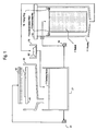
- a developing apparatus comprises a feeder 31 that feeds a developing solution 5 to an exposed printing raw plate 1; a dispersed-matter-filter 13, the developing solution 5 in which photosensitive resin composition separated from the photosensitive resin composition layer of the exposed printing raw plate 1 is dispersed being passed through the dispersed-matter-filter to flocculate the photosensitive resin composition dispersed in the developing solution 5; and a flocculated-matter-filter 15 that removes a flocculated photosensitive resin composition from the developing solution 5 passed through the dispersed-matter-filter 13.
- the dispersed-matter-filter 13 and a basket 7 that accommodates the dispersed-matter-filter 13 are shown by a side view, and a housing 11 is shown by a sectional view.
- the exposed printing raw plate 1 is disposed on a stage 41.
- a photosensitive resin composition is applied onto a support by a heat press molding method, a calendar process method or an extrusion molding method to form a photosensitive resin composition layer having a desired thickness in the exposed printing raw plate 1.
- the photosensitive resin composition is prepared by mixing a hydrophilic polymer, a photopolymerizable unsaturated monomer and a photopolymerization initiator by an extruder or a kneader. Materials having superior dimensional stability are preferably used for the support.
- the thickness of the support is preferably from 50 to 350 ⁇ m, and more preferably from 100 to 250 ⁇ m.
- an adhesive layer may be provided when necessary.
- the hydrophilic polymer included in the photosensitive resin composition refers to a polymer dissolved or swollen in water. Examples thereof include radical copolymers, polyamide polymers, polyvinyl alcohol polymers, polyester polymers, and urethane copolymers.
- the hydrophilic polymer may be used alone, or two or more thereof may be used in combination.
- the radical copolymer is obtained, for example, by copolymerization using not less than 1.0 part by mass of a hydrophilic unsaturated monomer in 100 parts by mass of unsaturated monomers.
- As the hydrophilic unsaturated monomer acidic functional group comprising unsaturated monomers are preferred.
- Examples of the acidic functional group comprising unsaturated monomers include ethylenic unsaturated monomers having a carboxyl group, a sulfonic acid group, a phosphoric acid group, a boric acid group, or a hydroxyl group.
- the amount of the acidic functional group comprising unsaturated monomer to be used based on the whole amount of the unsaturated monomers is preferably from 1 to 30 wt%. At an amount of the acidic functional group comprising unsaturated monomer to be used of not less than 1 wt%, the exposed printing raw plate can be aqueously developed.
- an amount of the acidic functional group comprising unsaturated monomer to be used of not more than 30 wt% increase in the amount of moisture absorbed by the photosensitive resin composition and in the amount of the photosensitive resin composition swollen by an ink can be suppressed. Moreover, high workability at the time of mixing the photosensitive resin composition can be obtained.
- Examples of the unsaturated monomer used for the radical copolymer include conjugated dienes, aromatic vinyl compounds, (meth)acrylic acid esters, ethylenic monocarboxylic acid alkyl ester monomers having a hydroxyl group, unsaturated dibasic acid alkyl esters, maleic anhydride, vinyl cyanide compounds, (meth)acrylamides and derivatives thereof, vinyl esters, vinyl ethers, vinyl halides, basic monomers having an amino group, vinylpyridines, olefins, silicon-containing ⁇ , ⁇ -ethylenically unsaturated monomers, and allyl compounds.
- the unsaturated monomer may be used alone, or two or more thereof may be used in combination. Also, a monomer having two or more addition-polymerizable groups may be used. Emulsion polymerization is preferred although the method for polymerizing the radical copolymer used for the first embodiment is not particularly limited.
- Use of from 10 to 70 parts by mass of the hydrophilic polymer based on 100 parts by mass of the photosensitive resin composition leads to good aqueous development properties and resistance against moisture absorption of the photosensitive resin composition layer.
- Examples of the photopolymerizable unsaturated monomer included in the photosensitive resin composition include unsaturated carboxylic acids of acrylic acids and methacrylic acids ((meth)acrylic acids) or ester compounds thereof (for example, alkyl (meth)acrylates, cycloalkyl (meth)acrylates, haloalkyl (meth)acrylates, alkoxyalkyl (meth)acrylates, hydroxyalkyl (meth)acrylates, aminoalkyl (meth)acrylates, tetrahydrofurfuryl (meth)acrylates, allyl (meth)acrylates, glycidyl (meth)acrylates, benzyl (meth)acrylates, phenoxy (meth)acrylates; mono- or di-(meth)acrylates of alkylene glycol or polyoxyalkylene glycol; trimethylolpropane tri(meth)acrylates; and pentaerythritol tetra(meth)acrylates); (meth
- the photopolymerizable unsaturated monomer may be used alone, or two or more thereof may be used in combination. Preferably, 1 to 30 parts by mass of the photopolymerizable unsaturated monomer is used based on 100 parts by mass of the photosensitive resin composition. Use of not less than 1 part by mass of the photopolymerizable unsaturated monomer based on 100 parts by mass of the photosensitive resin composition leads to superior forming properties of details and characters of a printing plate such as a flexographic printing plate formed using the photosensitive resin composition.
- the photopolymerizable unsaturated monomer can suppress deformation during storing or transporting the printing raw plate before the photosensitive resin composition layer is cured.
- the printing plate formed using the photosensitive resin composition can have proper hardness, and a solid portion has good ink deposition even in printing to a printed medium of low paper quality having unevenness on the surface thereof.
- Examples of the photopolymerization initiator included in the photosensitive resin composition include thioxanthones such as benzophenone, 4,4-bis(diethylamino)benzophenone, t-butylanthraquinone, 2-ethylanthraquinone, 2,4-diethylthioxanthone, isopropylthioxanthone, and 2,4-dichlorothioxanthone; acetophenones such as diethoxyacetophenone, 2-hydroxy-2-methyl-1-phenylpropan-1-one, benzyldimethylketal, 1-hydroxycyclohexyl phenyl ketone, 2-methyl-2-morpholino(4-thiomethylphenyl)propan-1-one, and 2-benzyl-2-dimethylamino-1-(4-morpholinophenyl)-butanone; benzoin ethers such as benzoin methyl ether, benzoin ethyl ether,
- the photopolymerization initiator may be used alone, or two or more thereof may be used in combination. Preferably, from 0.1 to 10 parts by mass of the photopolymerization initiator is used based on 100 parts by mass of the photosensitive resin composition. Use of not less than 0.1 parts by mass of the photopolymerization initiator based on 100 parts by mass of the photosensitive resin composition leads to superior forming properties of details and characters of a printing plate formed using the photosensitive resin composition. Use of not more than 10 parts by mass of the photopolymerization initiator based on 100 parts by mass of the photosensitive resin composition can suppress reduction in transmittance of active light such as ultraviolet rays, and thereby exposure can be performed under proper exposure sensitivity.
- active light such as ultraviolet rays
- the photosensitive resin composition may comprise a thermoplastic elastomer when necessary.
- the thermoplastic elastomer refers to elastomers that exhibit rubber elasticity in the vicinity of normal temperature, hardly deform plastically, and are plasticized with heat when the composition is mixed by an extruder.
- Examples of the thermoplastic elastomer include thermoplastic block copolymers, 1,2-polybutadiene, polyurethane elastomers, and chlorinated polyethylenes.
- the thermoplastic elastomer may be used alone, or two or more thereof may be used in combination.
- the thermoplastic elastomer the thermoplastic block copolymers are preferred, and polymers obtained by polymerizing a monovinyl-substituted aromatic hydrocarbon monomer and a conjugated diene monomer are more preferred.
- Examples of the monovinyl-substituted aromatic hydrocarbon monomer include styrene, ⁇ -methylstyrene, p-methylstyrene, and p-methoxystyrene.
- Examples of the conjugated diene monomer include butadiene and isoprene. By polymerization of these monomers, a styrene-butadienestyrene block copolymer and a styrene-isoprene-styrene block copolymer, for example, are obtained.
- the content of the monovinyl-substituted aromatic hydrocarbon segment in the thermoplastic elastomer is preferably from 8 to 50 wt%. At a content of not less than 8 wt%, occurrence of a cold flow of the photosensitive resin composition can be suppressed, and superior thickness accuracy is obtained. At a content of not more than 50 wt%, the printing plate formed using the photosensitive resin composition can have proper hardness, and has superior printing quality. Although vinyl-bond units in the conjugated diene segments of the thermoplastic elastomer contribute to improvement in reproducibility of a relief, they also cause increase in adhesiveness of the surface of the printing plate simultaneously.
- the average percentage of vinyl segments is preferably from 5 to 40%, and more preferably from 10 to 35%.
- the average percentage of vinyl segments refers to the proportion of vinyl-bond units based on the whole amount of double bonds other than the aromatic ring in the thermoplastic elastomer.
- thermoplastic elastomer Preferably from 5 to 50 parts by mass and more preferably from 10 to 40 parts by mass of the thermoplastic elastomer is used based on 100 parts by mass of the photosensitive resin composition when desired.
- Use of from 5 to 50 parts by mass of the thermoplastic elastomer based on 100 parts by mass of the photosensitive resin composition leads to good properties in a elongation ratio, water resistance and swelling resistance against ink of the printing plate.
- the photosensitive resin composition may comprise various auxiliary additives such as a plasticizer, a thermal polymerization inhibitor, an ultraviolet absorbing agent, an antihalation agent, and a light stabilizer, for example.
- auxiliary additives such as a plasticizer, a thermal polymerization inhibitor, an ultraviolet absorbing agent, an antihalation agent, and a light stabilizer, for example.
- the plasticizer include hydrocarbon oils having fluidity at normal temperature such as liquid naphthene oil and paraffin oil, liquid polybutadiene, liquid polyisoprene, modified products of liquid polybutadiene, liquid acrylonitrile-butadiene copolymers, liquid styrene-butadiene copolymers, and polystyrenes having a number average molecular weight of not more than 2,000, sebacic acid esters, and phthalic esters.
- a photopolymerizable reactive group may be attached to these structures.
- the plasticizer may be used alone, or two or more thereof may be used in
- thermal polymerization inhibitor examples include amide and hydrazide heavy metal deactivators, quenchers such as organic Ni quenchers, hindered piperidine HALS, phenol antioxidants such as hindered phenol antioxidants and semi-hindered phenol antioxidants, phosphorus antioxidants such as phosphite antioxidants and phosphonate antioxidants, thioether antioxidants, and sulfur antioxidants.
- quenchers such as organic Ni quenchers, hindered piperidine HALS
- phenol antioxidants such as hindered phenol antioxidants and semi-hindered phenol antioxidants
- phosphorus antioxidants such as phosphite antioxidants and phosphonate antioxidants
- thioether antioxidants examples include sulfur antioxidants.
- the thermal polymerization inhibitor may be used alone, or two or more thereof may be used in combination.
- ultraviolet absorbing agent examples include benzophenone ultraviolet absorbing agents, triazine ultraviolet absorbing agents, and benzotriazole ultraviolet absorbing agents. The ultraviolet absorbing agent may be used alone
- the exposed printing raw plate 1 shown in Figure 1 may further include an infrared ablation layer disposed on the photosensitive resin composition layer comprising the photosensitive resin composition.
- the infrared ablation layer is composed of a binder polymer, an infrared absorbing substance, and a non-infrared shielding substance, and is used as a mask layer at the time of exposure.
- binder polymer examples include styrene described in Japanese Patent Laid-Open No. 11-153865 , copolymers composed of a monovinyl-substituted aromatic hydrocarbon such as styrene, ⁇ -methylstyrene, and vinyltoluene and a conjugated diene such as butadiene and isoprene, those prepared by hydrogenating copolymers composed of a monovinyl-substituted aromatic hydrocarbon and a conjugated diene, polyamide described in Japanese Patent Laid-Open No.
- polyvinyl alcohol graft copolymers of polyvinyl alcohol/polyethylene glycol, amphoteric interpolymers, alkyl celluloses, hydroxyalkyl celluloses, nitrocelluloses, copolymers of ethylene and vinyl acetate, cellulose acetate butyrate, polybutyral, cyclic rubbers, copolymers of styrene and acrylic acid, and copolymers of polyvinyl pyrrolidone and vinyl acetate.
- the binder polymer may be used alone, or two or more thereof may be used in combination.
- the infrared absorbing substance examples include substances usually having a strong absorption wavelength at 750 to 2000 nm, and examples thereof include inorganic pigments such as carbon black, graphite, copper chromite, and chrome oxide, and pigments such as poly phthalocyanine compounds, cyanine dyes, and metal thiolate pigments. Among them, carbon black can be used in the wide range of a particle size of from 13 to 85 nm.
- the infrared absorbing substance is added to the infrared ablation layer in the range in which the infrared ablation layer is given sensitivity at which cutting off by a laser beam to be used is enabled.
- the amount of the infrared absorbing substance to be added is usually from 10 to 80 wt% based on the whole amount of the components of the infrared ablation layer.
- the infrared absorbing substance may be used alone, or two or thereof may be used in combination.
- non-infrared shielding substance examples include substances that reflect or absorb ultraviolet light, and examples thereof include an ultraviolet absorbing agent, carbon black, and graphite.
- the non-infrared shielding substance is added to the infrared ablation layer in the range at which a desired optical density can be achieved.
- the amount of the non-infrared shielding substance to be added based on the whole amount of the components of the infrared ablation layer is an amount such that a optical density may be usually not less than 2.0, and preferably not less than 3.0.
- the non-infrared shielding substance may be used alone, or two or more thereof may be used in combination.
- the infrared absorbing substance and the non-infrared shielding substance may be the same substance.
- a printing raw plate comprising a protective layer on the surface of the photosensitive resin composition layer
- a printing plate can be obtained by closely contacting an image carrier such as a negative film with the surface of the protective layer, and performing exposure and development.
- the protective layer include films that can be removed at a developing step, and examples thereof include a water-soluble cellulose coated film layer and a polyvinyl alcohol coated film layer.
- the printing raw plates comprising the protective layers described in Japanese Patent Laid-Open Nos. 51-49803 , 54-68224 , and 56-110941 can be used.
- the photosensitive resin composition layer of the exposed printing raw plate 1 is selectively exposed using active rays and a mask to be photo-cured.
- active rays include a low pressure mercury lamp, a high pressure mercury lamp, an ultraviolet fluorescence light, a carbon arc lamp, a xenon lamp, a zirconium lamp, and sunlight.
- the mask include a negative film and the infrared ablation layer ablated by an infrared laser.
- the developing solution 5 that develops the photosensitive resin composition layer of the exposed printing raw plate 1 disposed on the stage 41 comprises a surface active agent, and comprises a washing accelerator and/or a pH adjuster when desired.
- the surface active agent is a substance showing an action of dissolving in water to reduce the surface tension of water.
- examples of the surface active agent include nonionic, anionic, cationic, and amphoteric surface active agents.
- the surface active agent may be used alone, or two or thereof may be used in combination.
- the concentration of the surface active agent in the developing solution 5 is from 0.5 to 10 wt%, for example.
- nonionic surface active agent examples include higher alcohol alkylene oxide adducts, alkylphenol alkylene oxide adducts, fatty acid alkylene oxide adducts, polyhydric alcohol fatty acid ester alkylene oxide adducts, higher alkylamine alkylene oxide adducts, fatty acid amide alkylene oxide adducts, alkylene oxide adducts of fats and oils, and polypropylene glycol alkylene oxide adducts as polyethylene-glycol type, fatty acid esters of glycerol, fatty acid esters of pentaerythritol, fatty acid esters of sorbitol and sorbitan, and fatty acid esters of sucrose as polyhydric alcohol type, alkyl ethers of polyhydric alcohols, and fatty acid amides of alkanolamines.
- anionic surface active agent examples include linear alkylbenzene sulfonic acid salts having an alkyl group with the number of carbons of 8 to 16 on average, ⁇ -olefin sulfonic acid salts having the number of carbons of 10 to 20 on average, dialkyl sulfosuccinic acid salts having an alkyl group or alkenyl group with the number of carbons of 4 to 10, sulfonic acid salts of fatty acid lower alkyl esters, alkyl sulfuric acid salts having the number of carbons of 10 to 20 on average, alkyl ether sulfuric acid salts that have a linear or branched alkyl group or alkenyl group having the number of carbons of 10 to 20 on average and to which 0.5 to 8 mol of ethylene oxide on average is added, and saturated or unsaturated fatty acid salts having the number of carbons of 10 to 22 on average.
- Examples of the cationic surface active agent include alkylamine salts, alkylamine ethylene oxide adducts, alkyltrimethylammonium salts, alkyldimethylbenzylammonium salts, Sapamine-type quarternary ammonium salts, and pyridium salts.
- Examples of the amphoteric surface active agent include lauryl aminopropionic acid sodium and lauryldimethyl betaine.
- washing accelerator included in the developing solution 5 examples include amines such as monoethanolamine, diethanolamine, and triethanolamine; glycol ethers; ammonium salts such as tetramethylammonium hydroxide; and organic solvents such as paraffin hydrocarbons.
- Examples of the pH adjuster included in the developing solution 5 include sodium borate, sodium carbonate, sodium silicate, sodium metasilicate, sodium succinate, and sodium acetate.
- the developing solution 5 is temporarily stored in a developing solution tank 21.
- the feeder 31 such as a pump is connected to the developing solution tank 21.
- the developing solution 5 in the developing solution tank 21 is continuously fed to the exposed printing raw plate 1 through the feeder 31.
- the exposed printing raw plate 1 may be immersed in the developing solution 5, or the developing solution 5 may be sprayed from a spray nozzle to the exposed printing raw plate 1.
- the photosensitive resin composition in an unexposed portion of the photosensitive resin composition layer of the exposed printing raw plate 1 reacts with the developing solution 5 to disperse or dissolve in the developing solution 5.
- the photosensitive resin composition in the unexposed portion is scraped off from the exposed printing raw plate 1 using a brush 42.
- the photosensitive resin composition dispersed in the developing solution 5 is covered with the surface active agent included in the developing solution 5. For this reason, the photosensitive resin composition dispersed in the developing solution 5 tends to be kept dispersed without being flocculated in the developing solution 5.
- Each size of the dispersed photosensitive resin composition is 10 to 70 ⁇ m, for example.
- Part of the dispersed photosensitive resin composition may be flocculated in the developing solution 5 to float on the surface of the solution in the developing solution tank.
- the photosensitive resin composition flocculated in the developing solution tank comprises the hydrophilic polymer as a principal component, and comprises the thermoplastic elastomer, the plasticizer, and the infrared ablation layer component depending on the printing raw plate to be used.
- the photopolymerizable unsaturated monomer and the photopolymerization initiator dissolve in the developing solution, and therefore do not flocculate alone. The same goes for the photosensitive resin composition flocculated by the dispersed-matter-filter, which will be described later.
- the developing solution 5 comprising the dispersed photosensitive resin composition is again returned to the developing solution tank 21 through a developing tank 43.
- a feeder 32 such as a pump is further connected to the developing solution tank 21.
- At least part of the developing solution 5 stored in the developing solution tank 21 and comprising the dispersed photosensitive resin composition is sent into the cylindrical portion of the cylindrical dispersed-matter-filter 13 through the feeder 32.
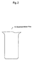
- the dispersed-matter-filter 13 is a bag-like bag filter, for example, and comprises a polymer such as polyester, viscose, polypropylene, nylon, Nomex, wool yarn, or fluororesin.
- the diameter of each fiber is 50 ⁇ m, for example.
- the dispersed-matter-filter 13 is accommodated in the mesh basket 7 having an approximately cylindrical shape, and the basket 7 is stored in the cylindrical housing 11.
- the dispersed-matter-filter 13 is fixed to the inside of the housing 11 by a fixing ring 16.
- the housing 11 is made of metal such as aluminum and stainless steel, for example.
- photosensitive resin compositions 61a, 61b, and 61c ... are accumulated in the inside of the film of the dispersed-matter-filter 13 as shown in Figure 3 .
- the photosensitive resin compositions 61a, 61b, and 61c ... accumulated in the inside of the film are rubbed against the dispersed-matter-filter 13, for example, and thereby the surface active agent that covers the surfaces of the photosensitive resin composition is removed.
- the flocculates 62 are pushed out to the outside from the inside of the film of the dispersed-matter-filter 13 by pressure such as hydraulic pressure, and deposited between the outside of the dispersed-matter-filter 13 and the inside of the basket 7.
- the flocculated photosensitive resin composition flocculated in the developing solution tank 21 may also be pushed out to the outside of the filter.
- the developing solution 5 comprising the dispersed photosensitive resin composition may be passed from the outside to the inside of the bag-like dispersed-matter-filter 13.
- the developing solution 5 may comprise the components of the infrared ablation layer peeled off during development.
- the developing solution 5 comprises the components of the infrared ablation layer
- the components of the infrared ablation layer are incorporated into the flocculates 62 formed in the dispersed-matter-filter 13.
- the dispersed-matter-filter 13 can flocculate the photosensitive resin composition dispersed in the developing solution 5 and catch the components of the infrared ablation layer simultaneously and suitably. The same goes for the case where the components of the infrared ablation layer included in the developing solution 5 are already included in the developing solution before the exposed printing raw plate 1 shown in Figure 1 is developed.
- P 1 is the pressure in the space of the surface side of the dispersed-matter-filter 13 facing upstream of the flow of the developing solution 5 shown in Figure 1 , namely, the pressure in the space of the feed side of the dispersed-matter-filter 13, specifically, the pressure in the space of the internal surface side of the bag-like dispersed-matter-filter 13.
- P 2 is the pressure in the space of the surface side of the dispersed-matter-filter 13 facing downstream of the flow of the developing solution 5, namely, the pressure in the space of the discharge side of the dispersed-matter-filter 13, specifically, the pressure in the space of the external surface side of the bag-like dispersed-matter-filter 13.
- the pressure in the space of the feed side of the dispersed-matter-filter 13 be increased, and/or that in the space of the discharge side of the dispersed-matter-filter 13 be reduced.
- the relationship between the pressure P 1 and the pressure P 2 is preferably 0.02 MPa ⁇ P 1 - P 2 ⁇ 2 MPa, more preferably 0.04 MPa ⁇ P 1 - P 2 ⁇ 1 MPa, and still more preferably 0.06 MPa ⁇ P 1 - P 2 ⁇ 0.5 MPa. If the difference between the pressure P 1 and the pressure P 2 is not less than 0.02 MPa, flocculation of the photosensitive resin compositions 61a, 61b, and 61c ... shown in Figure 3 is facilitated. If the difference between the pressure P 1 and the pressure P 2 is not more than 2 MPa, load on the dispersed-matter-filter 13 and other components in the developing apparatus can be reduced.
- the difference between the pressure P 1 and the pressure P 2 can be set by increasing the pressure P 1 in the space of the internal surface side of the dispersed-matter-filter 13 by the feeder 32 such as a pump shown in Figure 1 , in the case where P 2 is an atmospheric pressure, for example. Air pressure may be applied to the internal surface of the bag-like dispersed-matter-filter 13.
- the space of the internal surface side of the dispersed-matter-filter 13 is preferably substantially a closed space if it is thought that the dispersed-matter-filter 13 is also an outer wall.
- the pressure in the space of the outer side surface of the bag-like dispersed-matter-filter 13 may be reduced by a pump or an aspirator.
- the space of the external surface side of the dispersed-matter-filter 13 is preferably substantially a closed space if it is thought that the dispersed-matter-filter 13 is also an outer wall.
- Increase in the pressure P 1 and reduction in the pressure P 2 may be used in combination.
- the pressure P 1 may be the pressure in the space of the external surface side of the dispersed-matter-filter 13, or the pressure P 2 may be the pressure in the space of the internal surface side of the dispersed-matter-filter 13.
- the thickness of the dispersed-matter-filter 13 is preferably not less than 0.01 mm and not more than 10 mm, and more preferably not less than 0.5 mm and not more than 5 mm. At a thickness of not less than 0.01 mm, the flocculation efficiency of the dispersed photosensitive resin composition is increased. At a thickness of not more than 10 mm, the pressure applied to the dispersed-matter-filter 13 can be adjusted to a proper pressure.
- the thickness of the dispersed-matter-filter can be measured as follows: a thickness meter ID-F125 made by Mitutoyo Corporation is attached to a BIEFFEBI Spessimetor 2, and set such that the a load of 1.0 kg may be applied to a contact surface having a diameter of 1 cm.
- the density of the dispersed-matter-filter 13 is preferably not less than 0.05 g/cm 3 and not more than 1 g/cm 3 , and more preferably not less than 0.07 g/cm 3 and not more than 0.5 g/cm 3 .
- the flocculation efficiency of the dispersed photosensitive resin composition tends to be increased.
- the pressure applied to the dispersed-matter-filter 13 can be adjusted to a proper pressure.
- the density can be calculated by cutting the dispersed-matter-filter 13 into 10 cm x 10 cm, and weighing the weight.
- a filter having one type of opening may be used, or several layers of filters having the same or different openings may be disposed.
- the dispersed photosensitive resin composition is preferably not less than 0.16 parts by mass and not more than 6 parts by mass and more preferably not less than 0.6 parts by mass and not more than 3 parts by mass based on 100 parts by mass of the developing solution, the dispersed photosensitive resin composition is suitably flocculated by the dispersed-matter-filter 13.
- the developing solution 5 passed through the dispersed-matter-filter 13 is fed to the flocculated-matter-filter 15.
- the developing solution 5 passed through the dispersed-matter-filter 13 may comprise the flocculates flocculated by the dispersed-matter-filter 13.
- the flocculated-matter-filter 15 catches the flocculates 62 included in the developing solution 5.
- the shape and material of the flocculated-matter-filter 15 is not particularly limited as long as the flocculated-matter-filter can catch the flocculates 62 included in the developing solution 5.
- the flocculated-matter-filter 15 that catches the flocculates 62 needs to be replaced by another flocculated-matter-filter 15 when the amount of the caught flocculates 62 approaches the capacity of the flocculated-matter-filter 15. For this reason, a shape and material enabling periodic replacement and taking out of the filter are preferably used.
- the flocculated-matter-filter 15 include nets produced from nylon, polyethylene, polypropylene, polyester, and polyethylene terephthalate (PET), a stainless steel mesh filter having an opening of 0.3 mm, fabrics, and nonwoven fabrics.
- the developing solution 5 passed through the flocculated-matter-filter 15 is returned to the developing solution tank 21 again.
- the photosensitive resin composition dispersed in the developing solution 5 can be flocculated by the dispersed-matter-filter 13, and the flocculates can be removed from the developing solution 5 efficiently by the flocculated-matter-filter 15.
- the photosensitive resin composition is flocculated by the dispersed-matter-filter 13 without using a flocculant that weakens the action of the surface active agent. For this reason, the developing solution 5 passed through the flocculated-matter-filter 15 can be used for development of the photosensitive resin composition layer again.
- the technique for reusing a developing solution is known.
- a fine filter that can catch the photosensitive resin composition dispersing in the developing solution is used, clogging is caused in a short time and frequent replacement of the filter is required.
- the developing solution filtered by a coarse filter is reused, the photosensitive resin composition dispersing in the developing solution adheres to the surface of the exposed printing raw plate and flocculates thereon, leading to deterioration of quality of the printing plate produced.
- a process for flocculating dispersing resin components by using a flocculant is also known.
- the photosensitive resin composition in the unexposed portion of the photosensitive resin composition layer is flocculated by a flocculant immediately after the photosensitive resin composition is dispersed in the developing solution, and adheres to the photosensitive resin composition layer.
- This also leads to deterioration of quality of the printing plate produced.
- pH or a temperature is controlled to weaken the surface active agent, and thereby the photosensitive resin composition dispersing in the developing solution is flocculated. This operation is complicated, however.
- the photosensitive resin composition dispersed in the developing solution 5 can be removed effectively without a flocculant even by use of a fine filter. Control of pH or a temperature is also unnecessary. For that reason, the photosensitive resin composition dispersed in the developing solution 5 can be simply removed at low cost in a short time. Accordingly, quality of the printing plate produced can be improved at low cost.
- addition of the flocculant to the developing solution 5 may cause clogging in the dispersed-matter-filter 13. Rather, it is preferred that no flocculant be used.
- the flocculates flocculated in the developing solution tank 21 are selectively sucked, and fed to the dispersed-matter-filter 13, and thereby the flocculates can be recovered before the flocculates excessively grow. As a result, the frequency that a worker cleans the developing solution tank 21 can be reduced.
- the developing solution 5 be sucked in the vicinity of the upper portion of the developing solution tank 21, and fed to the dispersed-matter-filter 13.
- the developing solution 5 is preferably sucked in the vicinity of the bottom of the developing solution tank 21, and fed to the dispersed-matter-filter 13.
- the dispersed-matter-filter 13 shown in Figure 1 is a bag filter, and comprises a polymer.
- a bag-like dispersed-matter-filter 8 is a mesh filter made of metal such as aluminum and stainless steel and provided with a mesh with an opening of 10 ⁇ m, for example.
- the dispersed-matter-filter 8 is a filter made of metal, the basket that accommodates the dispersed-matter-filter 8 may be eliminated.
- Other components of the developing apparatus according to the second embodiment are the same as those of the first embodiment.
- the dispersed-matter-filter 8 is shown by a side view, and the housing 11 is shown by a sectional view. Also in the developing apparatus according to the second embodiment, the photosensitive resin composition dispersed in the developing solution 5 can be flocculated effectively by the dispersed-matter-filter 8.
- the dispersed-matter-filter 13 is a bag filter and comprises a polymer, for example.
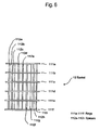
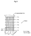
- the basket 12 that accommodates the dispersed-matter-filter 13 has approximately a cylindrical shape, and comprises a plurality of rings 111a, 111b, 111c, 111d, 111e, and 111f disposed in parallel such that the respective centers thereof may be located on the same line, and a plurality of strip-like spacers 112a, 112b, 112c, 112d, 112e, 112f, 112g, 112h, and 112i ... that connect the inner circumferences of the plurality of rings 111a to 111f ... to each other.
- the plurality of rings 111a to 111f is congruent, for example.
- the plurality of spacers 112a to 112i is also congruent, for example.
- the plurality of spacers 112a to 112i is radially disposed so as to contact the respective inner circumferences of the plurality of rings 111a to 111f.
- the plurality of spacers 112a to 112i is disposed vertically to the tangent of each inner circumference of the plurality of rings 111a to 111f.
- the plurality of rings 111a to 111f and the plurality of spacers 112a to 112i are made of metal such as aluminum and stainless steel, for example.
- the dispersed-matter-filter 13 is accommodated within the plurality of spacers 112a to 112i.
- the basket 12 in which the dispersed-matter-filter 13 is accommodated is housed in the cylindrical housing 11 as shown in Figure 10 , and covered with a lid 14 as shown in Figure 11 .
- the dispersed-matter-filter 13 and the basket 12 are shown by a side view, and the housing 11 is shown by a sectional view.
- a space is provided between each of the plurality of spacers 112a to 112i of the basket 12 and the inner wall of the housing 11.
- a space is also provided between the plurality of rings 111a to 111f of the basket 12 and the inner wall of the housing 11.
- photosensitive resin compositions 61a, 61b, and 61c pass through the dispersed-matter-filter 13 to be flocculated, and thereby flocculates 62 are deposited between the outside of the dispersed-matter-filter 13 and the plurality of rings 111a to 111d of the basket 12.
- the space is provided between the rings 111a to 111d of the basket 12 and the inner wall of the housing 11. For this reason, the flocculates 62 separated from above the rings 111a to 111d are flowed downstream.
- the space be provided between each of the plurality of spacers 112a to 112i and the inner wall of the housing 11 and/or between the rings 111a to 111d and the inner wall of the housing 11, to prevent the plurality of spacers 112a to 112i and the rings 111a to 111d from contacting any objects other than the dispersed-matter-filter 13, the developing solution 5, and the flocculates.
- the width of the space is 8 mm, for example.
- An interval D at which the plurality of spacers 112a to 112i shown in Figure 13 are disposed is preferably not less than 5 mm and not more than 50 mm.
- the interval D means an interval between spacers in the innermost portion of the space that contacts the dispersed-matter-filter.
- the space in which the flocculates are deposited can be secured on the outside of the bag-like dispersed-matter-filter 13.
- the inside of the bag-like dispersed-matter-filter 13 is given a pressure not less than 0.02 MPa higher than that of the outside thereof, at an interval D of not more than 50 mm, deflection of the bag-like dispersed-matter-filter 13 can be prevented. At an interval D of not less than 5 mm and not more than 50 mm, deflection of the dispersed-matter-filter 13 is prevented, and bias of the pressure applied to the dispersed-matter-filter 13 is reduced. Thereby, the photosensitive resin composition dispersing in the developing solution 5 can be efficiently flocculated, and the flocculates 62 can be efficiently pushed and flowed to the flocculated-matter-filter 15.
- Each width L of the plurality of spacers 112a to 112i shown in Figure 13 is preferably not less than 3 mm and not more than 30 mm.
- Each thickness W of the plurality of spacers 112a to 112i is preferably shorter than the interval D at which the plurality of spacers 112a to 112i are disposed.
- the thickness W is preferably not less than 1/1000 and not more than 1/2 of the interval D, more preferably not less than 1/100 and not more than 1/5 thereof, and still more preferably not less than 1/70 and not more than 1/10 thereof.
- the flocculates deposited on the outside of the dispersed-matter-filter 13 and the basket 12 are pushed and flowed to the flocculated-matter-filter 15 by pressure such as hydraulic pressure, for example.
- the deposited flocculates may be scraped by a spatula or a brush, or the deposited flocculates may be peeled off using a liquid or a gas. Thereby, quality of the printing plate produced can be further improved.
- the photosensitive resin composition dispersed in the developing solution 5 can be effectively flocculated by the dispersed-matter-filter 13, and the flocculates 62 formed in the dispersed-matter-filter 13 can be efficiently carried to the flocculated-matter-filter 15.
- the developing apparatus further comprises a rinse brush 51 as shown in Figure 14 .
- the developing solution 5 passed through the flocculated-matter-filter 15 is fed to the vicinity of the rinse brush 51 by the feeder 33 such as a pump.
- the exposed printing raw plate 1 from which the photosensitive resin composition of the unexposed portion is selectively removed using the developing solution 5 fed by the feeder 31 and the brush 42 is conveyed by the movable stage 41 to under the rinse brush 51.
- the feeder 31 may spray the developing solution 5 passed through the flocculated-matter-filter 15 to the exposed printing raw plate 1, or may feed the developing solution such that the surface of the printing raw plate 1 may be covered with the developing solution.
- the exposed printing raw plate 1 may be immersed in the developing solution 5 passed through the flocculated-matter-filter 15.
- the surface of the exposed printing raw plate 1 is cleaned up by the rinse brush 51 to remove the developing solution 5 that may remain on the surface of the exposed printing raw plate 1 and comprises the dispersed photosensitive resin composition and the flocculated photosensitive resin composition.
- the photosensitive resin composition dispersed in the developing solution may adhere to the exposed printing raw plate again. For that reason, in the related art, the exposed printing raw plate is rinsed using a unused fresh developing solution.
- the photosensitive resin composition dispersed in the developing solution 5 is flocculated by the dispersed-matter-filter 13, and the flocculated photosensitive resin composition are caught in the flocculated-matter-filter 15. For that reason, the concentration of the dispersed photosensitive resin composition is extremely low in the developing solution 5 passed through the flocculated-matter-filter 15.
- the developing solution 5 passed through the flocculated-matter-filter 15 can be reused to rinse the exposed printing raw plate 1 after development. Reuse of the developing solution 5 passed through the flocculated-matter-filter 15 can reduce the amount of the developing solution 5 to be used, and can also reduce cost at the developing step.
- the developing apparatus may comprise several other rinse brushes 52 and several washing brushes 53.
- a developing solution comprising no resin component is sprayed from the rinse brush 52, pure water or the like is sprayed from the washing brush 53 to the exposed printing raw plate 1, and the exposed printing raw plate 1 is cleaned up by the rinse brush 52 and the washing brush 53.
- the developing solution 5 passed through the flocculated-matter-filter 15 may be used for the developing solution sprayed from the rinse brush 52. Use of the developing solution 5 passed through the flocculated-matter-filter 15 can reduce the amount of the developing solution to be prepared newly.
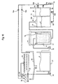
- the developing apparatus and filter apparatus may further comprise a settling tank for the developing solution passed through the flocculated-matter-filter.
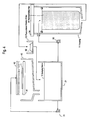
- the developing apparatus may comprise a settling tank 71.
- the developing solution 5 passed through the flocculated-matter-filter 15 may be directly fed to the settling tank 71, or may be fed to the settling tank 71 by the feeder 33 after the developing solution 5 is once fed to a developing solution tank 120 for a developing solution passed through the flocculated-matter-filter 15 as shown in Figures 15 to 17 .
- the developing solution tank 120 for a developing solution passed through the flocculated-matter-filter 15 the developing solution tank 120 and/or the settling tank 71 may be provided with a temperature control mechanism for the developing solution.
- a structure in which the developing solution tank 120 and the settling tank 71 are separated by a partition is preferred. By the structure, the developing solution overflowed from the settling tank returns to the developing solution tank again without leakage to the outside. For this reason, such a structure is preferred from the viewpoint of safety.
- settling means the state where the developing solution in the settling tank is separated into a high concentration layer and a low concentration layer.
- settling in the present embodiment means the state where no developing solution flows into the settling tank at all, and any state where the developing solution in the settling tank is separated into a high concentration layer and a low concentration layer even if the developing solution continuously flows into the settling tank. Whether one of the high concentration layer and the low concentration layer is on the upper layer side or the lower layer side in the settling tank changes with the specific gravity of the dispersing object to the developing solution, and is not particularly limited.
- the developing solution passed through the flocculated-matter-filter 15 is not fed to the settling tank 71 during a period of time when a fixed amount of the developing solution is fed to the settling tank 71 and the high concentration layer 81 is separated from the low concentration layer 82 by settling, and that the developing solution is fed to the developing solution tank 21 when a valve 705 is opened.
- the developing solution By settling the developing solution passed through the flocculated-matter-filter 15 in the settling tank 71, the developing solution is separated into the high concentration layer 81 mainly comprising the photosensitive resin composition and the low concentration layer 82 mainly comprising the developing solution.
- the time to settle the developing solution is not particularly limited as long as a fixed amount of the high concentration layer and that of low concentration layer are separated. From the viewpoint of productive efficiency, settling for not less than 5 minutes and not more than 24 hours is preferred, and settling for not less than 10 minutes and not more than 12 hours is more preferred.
- At least not less than 40 percent and preferably not less than 60 percent of the low concentration layer based on the volume of the developing solution in the settling tank be obtained by settling of the developing solution passed through the flocculated-matter-filter.
- the high concentration layer and the low concentration layer mean the layers having relatively different concentrations of the photosensitive resin composition of each layer.
- the photosensitive resin composition included in the high concentration layer and low concentration layer refer to all the components included in the photosensitive resin composition layer.
- the concentration of the high concentration layer and that of the low concentration layer depend on the developing solution and photosensitive resin composition to be used, and is not particularly limited.
- the concentration of the photosensitive resin composition in the low concentration layer is any concentration lower than the concentration of the photosensitive resin composition in the developing solution before separation, and not particularly limited.
- the concentration of not less than 0.001 g/L and not more than 20 g/L is preferred, that of not less than 0.001 g/L and not more than 15 g/L is more preferred, and that of not less than 0.001 g/L and not more than 10 g/L are still more preferred.
- the concentration of the photosensitive resin composition in the high concentration layer is any concentration higher than the concentration of the photosensitive resin composition in the developing solution before separation, and not particularly limited.
- the concentration is preferably not less than 1.5 times, more preferably not less than 2 times, and still more preferably not less than 5 times based on the concentration of the low concentration layer.
- an alkali builder may be added to the developing solution in the range in which performance of the developing solution is not influenced, or operation to increase the temperature of the developing solution in the settling tank only or the entire developing solution may be performed.
- the concentration of the photosensitive resin composition in the developing solution is high, the developing solution tends to be separated into the high concentration layer and the low concentration layer for a short time.
- the high concentration layer separated in the settling tank 71 is preferably removed from the settling tank.
- the high concentration layer 81 is exemplified as the upper layer of the low concentration layer 82.
- Examples of a method for removing a high concentration layer include, but not limited to, a method for providing an exit according to the specific gravity of the high concentration layer and the low concentration layer, a method for overflowing a high concentration layer to a tank for recovering a high concentration layer in the case where the specific gravity of the high concentration layer is smaller than that of a low concentration layer, and a method for downflowing a high concentration layer to a tank for recovering a high concentration layer in the case where the specific gravity of the high concentration layer is greater than that of a low concentration layer.
- the settling tank 71 preferably has an exit 72 for extracting the high concentration layer.
- the position of the exit 72 is not particularly limited as long as the high concentration layer can be extracted.
- the exit is preferably located in an upper portion of the settling tank if the specific gravity of the high concentration layer is smaller than that of the low concentration layer.
- the exit is preferably located in a lower portion of the settling tank if the specific gravity of the high concentration layer is greater than that of the low concentration layer.
- a valve 706 can be opened to remove the high concentration layer 81 from the exit 72. While the method for removing the high concentration layer has been exemplified, the low concentration layer separated in the settling tank may be extracted.
- the low concentration layer separated in the settling tank may be fed to the developing solution tank 21, or may be fed to the exposed printing raw plate 1 at the developing step as a developing solution.
- the developing apparatus may further include the rinse brush 51.
- the low concentration layer separated in the settling tank may be fed to the rinse brush, or may be used as a rinse solution for the photosensitive resin composition layer after the developing step.
- the low concentration layer separated in the settling tank has an extremely small amount of the dispersed and flocculated photosensitive resin composition. Accordingly, use of the low concentration layer as a rinse fed to the rinse brush is preferred.
- the valve 703 and the valve 704 can be opened to feed the low concentration layer to the rinse brush 51.
- the developing solution is settled in the settling tank, and thereby the dispersed photosensitive resin composition is separated as the high concentration layer.
- the high concentration layer to be discarded can be obtained simply and selectively, and the amount of the developing solution to be discarded can be reduced.
- the developing apparatus comprises the rinse brush 51
- the exposed printing raw plate 1 from which the photosensitive resin composition of the unexposed portion is selectively removed using the developing solution 5 fed by the feeder 31 and the brush 42 is conveyed by the movable stage 41 to under the rinse brush 51.
- the developing solution 5 passed through the flocculated-matter-filter 15 may be sprayed from the feeder 31 to the exposed printing raw plate 1 conveyed to under the rinse brush 51, or may be fed such that the surface of the exposed printing raw plate may be covered with the developing solution.
- the exposed printing raw plate 1 may be immersed in the developing solution 5 passed through the flocculated-matter-filter 15.
- the developing solution 5 passed through the flocculated-matter-filter 15 may be directly sprayed from the feeder 33 to the exposed printing raw plate 1, or may be fed such that the surface of the exposed printing raw plate may be covered with the developing solution.
- the printing raw plate 1 may be immersed in the developing solution 5 passed through the flocculated-matter-filter 15. Further, the low concentration layer separated the settling tank may be sprayed from the feeder 33 to the exposed printing raw plate 1, or may be fed such that the surface of the exposed printing raw plate may be covered with the low concentration layer. The exposed printing raw plate 1 may be immersed in the low concentration layer. The surface of the exposed printing raw plate 1 is cleaned up by the rinse brush 51 to remove the developing solution 5 that may comprise the dispersed photosensitive resin composition and may remain on the surface of the exposed printing raw plate 1 and the flocculated photosensitive resin composition.
- the photosensitive resin composition dispersed in the developing solution 5 is flocculated by the dispersed-matter-filter 13
- the photosensitive resin composition flocculated by the flocculated-matter-filter 15 is caught, and the dispersed photosensitive resin composition not caught by the dispersed-matter-filter and the flocculated-matter-filter is separated as the high concentration layer in the settling tank 71.
- the low concentration layer 82 in the settling tank 71 has an extremely low concentration of the dispersed photosensitive resin composition, and thus the low concentration layer 82 in the settling tank 71 can be suitably used as a rinse solution for the exposed printing raw plate 1 after development.
- no flocculant is added to the low concentration layer 82 in the settling tank 71.
- Reuse of the low concentration layer 82 in the settling tank 71 can reduce the amount of the developing solution 5 to be used, and can reduce cost at the developing step.
- the developing solution passed through the flocculated-matter-filter 15 can also be used as a rinse solution depending on the state of the developing solution.
- the developing apparatus may comprise several other rinse brushes 52 and several washing brushes 53.
- a developing solution comprising no resin component is sprayed from the rinse brush 52, pure water for example is sprayed from the washing brush 53 to the exposed printing raw plate 1, and the exposed printing raw plate 1 is cleaned up by the rinse brush 52 and the washing brush 53.
- the low concentration layer 82 in the settling tank 71 may be used for the developing solution sprayed from the rinse brush 52. Use of the low concentration layer 82 in the settling tank 71 can reduce the amount of the developing solution to be prepared newly.
- the photosensitive resin composition dispersd in the developing solution 5 can be flocculated by the dispersed-matter-filter 13, the flocculates can be efficiently removed from the developing solution 5 by the flocculated-matter-filter 15, and the dispersed photosensitive resin composition included in the developing solution can be separated as the high concentration layer by the settling tank 71.
- the developing solution used in the conventional developing step without using the dispersed-matter-filter 13 is not separated into the high concentration layer and the low concentration layer even if it is settled for not less than one day, unless the developing solution is heated or the concentration of sodium carbonate in the developing solution is increased.
- the developing solution passes through the dispersed-matter-filter 13, and thereby the component of the surface active agent in the developing solution is isolated from the photosensitive resin composition, or the surface active agent is incorporated into the flocculates; then, the component of the surface active agent needed to keep the developing solution dispersed is relatively reduced; for this reason, separation of the developing solution into the high concentration layer and the low concentration layer only by settling is facilitated after the photosensitive resin composition flocculated by the flocculation filter is removed.
- the photosensitive resin composition is flocculated by the dispersed-matter-filter 13 without using a flocculant that weakens the surface active agent
- the developing solution 5 passed through the flocculated-matter-filter 15 can be used at the developing step again.
- the low concentration layer 82 in the settling tank 71 has an extremely small content of the dispersing photosensitive resin composition, and can be suitably used as a rinse solution.
- a printing plate can be produced using a developing apparatus according to the present embodiment.
- a process for producing a printing plate according to the present embodiment comprises the steps of: feeding a developing solution to an exposed photosensitive resin composition layer; passing the developing solution in which photosensitive resin composition is dispersed through a dispersed-matter-filter to flocculate the photosensitive resin composition dispersed in the developing solution by the dispersed-matter-filter; and removing the flocculated photosensitive resin composition from the developing solution passed through the dispersed-matter-filter.
- a separate feeder that can feed the developing solution to the exposed printing raw plate 1 may also be provided in the present embodiment.
- the developing solution is fed to the exposed printing raw plate 1 by the feeder 31 to feed the developing solution to the exposed photosensitive resin composition layer. Then, the developing solution in which the photosensitive resin composition obtained by developing the photosensitive resin composition layer is dispersed is collected in the developing solution tank 21, and fed from the developing solution tank 21 to the dispersed-matter-filter 13 through the feeder 32. The photosensitive resin composition dispersed in the developing solution is flocculated by the dispersed-matter-filter 13. The developing solution passed through the dispersed-matter-filter is sent to the flocculation filter 15 to remove the photosensitive resin composition flocculated by the flocculated-matter-filter 15.
- a process for producing a printing plate may comprise the steps of: feeding a developing solution to an exposed photosensitive resin composition layer; passing the developing solution in which photosensitive resin composition is dispersed through a dispersed-matter-filter to flocculate the photosensitive resin composition dispersed in the developing solution by the dispersed-matter-filter; removing the flocculated photosensitive resin composition from the developing solution passed through the dispersed-matter-filter; and settling the developing solution, from which the flocculated photosensitive resin composition is removed, in a settling tank to separate the developing solution into a high concentration layer and a low concentration layer.
- the developing solution in which the photosensitive resin composition obtained by developing the photosensitive resin composition layer is dispersed is collected in the developing solution tank 21, and fed from developing solution tank 21 to the dispersed-matter-filter 13 through the feeder 32. Then, the photosensitive resin composition dispersed in the developing solution is flocculated by the dispersed-matter-filter 13.
- the developing solution passed through the dispersed-matter-filter is sent to the flocculation filter 15 to remove the photosensitive resin composition flocculated by the flocculation filter 15. Then, the developing solution passed through the flocculation filter is settled in the settling tank to be separated into the high concentration layer and the low concentration layer.
- the high concentration layer may be extracted from the exit provided in the settling tank.
- the low concentration layer may be fed to the rinse brush, or may be fed to the developing solution tank 21.
- the developing solution passed through the flocculation filter may be directly sent to the developing solution tank in the range in which it is not deviated from the object of the present invention.
- the printing raw plate was exposed from the support side using an ultraviolet-rays exposure machine made by Asahi Kasei E-materials Corp. "AFP-912EDLF” (trademark) such that the thickness of a cured layer including the thickness of the support of the printing raw plate might be 0.54 mm.
- AFP-912EDLF trademark
- a pattern at an image area rate of 30% was drawn in the infrared ablation layer using a laser drawing machine "CDI SPARK 4260" (trademark) made by ESKO ARTWORKS.
- the printing raw plate was exposed for 7 minutes from the infrared ablation layer side by the exposure machine to obtain an exposed printing raw plate.
- a pressure filtration apparatus comprising the basket 7, the housing 11, the lid 14, the fixing ring 16, and the feeder 32
- a pressure filtration apparatus "Kasupon filter MCF-0420TS” (trademark) made by Mitaka, Co., Ltd. was used. The lid 14 was closed.
- a polypropylene filter "R-10-PP-12-ES” (trademark) (thickness of 2.3 mm, density of 0.147 g/cm 3 ) made by Kajika Corporation was used.
- ADP-220W aqueous development printing developing machine made by Asahi Kasei E-materials Corp. was used.
- the developing solution 250 lit. of a fresh developing solution was prepared in the developing solution tank 21, the developing solution being prepared by diluting "W300" (trademark) made by Asahi Kasei E-materials Corp. by water such that the concentration might be 6 wt%, and comprising 0.4 wt% of sodium carbonate.
- W300 trademark
- the developing solution treated by the procedure above included 4 kg of the photosensitive resin composition component (except the photosensitive resin composition layer component and the photopolymerizable unsaturated monomer component) and the infrared ablation layer component in total.
- Treatment performance of the developing solution was evaluated in the same manner as that in Example 1 except that a pressure filtration apparatus "Eco Filter EF803" (trademark) made by Russell Finex Ltd. was used as the pressure filtration apparatus, and a stainless steel mesh filter having an opening of 10 ⁇ m, which was described according to the second embodiment, was attached as the dispersed-matter-filter 13. 2.0 kg of flocculate was recovered on the inside of the dispersed-matter-filter 13, 0.2 kg of flocculate was recovered on the outside thereof, and 2.0 kg of flocculate was recovered on the flocculated-matter-filter 15, respectively.
- a pressure filtration apparatus "Eco Filter EF803" trademark
- a stainless steel mesh filter having an opening of 10 ⁇ m which was described according to the second embodiment
- a polypropylene filter "R-1-PP-12-ES” (trademark) (thickness of 2.4 mm, density of 0.174 g/cm 3 ) made by Kajika Corporation was used.
- ADP-220W aqueous development printing developing machine made by Asahi Kasei E-materials Corp. was used.
- the developing solution 5 As the developing solution 5, the developing solution treated in the same manner as in Example 1 was used.
- the time needed to develop one exposed printing raw plate was 0.5 hours on average.
- the exposed printing raw plate was developed in the same manner as in Example 3 except that a polypropylene filter "R-10-PP-12-ES” (trademark) made by Kajika Corporation (thickness of 2.3 mm, density of 0.147 g/cm 3 ) with a degree of filtration of 10 ⁇ m was used as the dispersed-matter-filter. Then, the interlock of the pressure filtration apparatus was operated when six exposed printing raw plates were developed, and development was completed.
- a polypropylene filter "R-10-PP-12-ES” trademark
- Kajika Corporation thickness of 2.3 mm, density of 0.147 g/cm 3
- the exposed printing raw plate was developed in the same manner as in Example 3 except that a polypropylene filter "R-25-PP-12-ES” (trademark) made by Kajika Corporation (thickness of 2.2 mm, density of 0.137 g/cm 3 ) with a degree of filtration of 25 ⁇ m was used as the dispersed-matter-filter. Then, the interlock of the pressure filtration apparatus was operated when seven exposed printing raw plates were developed, and development was completed.
- the exposed printing raw plate was developed in the same manner as in Example 3 except that a polypropylene filter "R-100-PP-12-ES” (trademark) made by Kajika Corporation (thickness of 1.7 mm, density of 0.184 g/cm 3 ) with a degree of filtration of 100 ⁇ m was used as the dispersed-matter-filter. Then, the interlock of the pressure filtration apparatus was operated when eleven exposed printing raw plates were developed, and development was completed.
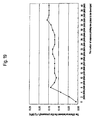
- Figure 18 shows the relationship between the number of the exposed printing raw plates developed and the difference between the filter pressures according to Examples 3 to 6.
- the values in the portion surrounded by a square show the filtration accuracies of the dispersed-matter-filters used in Examples 3 to 6.
- the exposed printing raw plate was developed in the same manner as in Example 4 except that the basket described in the third embodiment and having the plurality of spacers and the plurality of rings was used for the pressure filtration apparatus. Then, as shown in Figure 19 , the difference between the filter pressures was equilibrating at 0.14 MPa at maximum until the number of the exposed printing raw plate developed reached 30 sheets, even if the exposed printing raw plate was continuously developed. Thirty or more exposed printing raw plates could be developed. Accordingly, it was shown that the exposed printing raw plate can be continuously developed by use of the basket as shown in Figures 6 and 7 .
- the flocculate formed by the dispersed-matter-filter could be suitably recovered by the flocculated-matter-filter.
- Each width of the plurality of spacers was 15 mm, and the interval D between the plurality of spacers was 12 mm in the inside of the space that contacted the dispersed-matter-filter.
- the photosensitive resin composition dispersed in the aqueous developing solution was flocculated suitably, and could be recovered by the flocculated-matter-filter.
- the exposed printing raw plate was developed in the same manner as in Example 3 except that the lid 14 was removed so that both of the spaces on the internal surface side and the external surface side of the dispersed-matter-filter had the atmospheric pressure, and continuous platemaking performance was evaluated. Then, the dispersed-matter-filter was clogged when one exposed printing raw plate was developed, and the amount of the developing solution coming out from the dispersed-matter-filter was extremely reduced. Accordingly, development was completed.
- the exposed printing raw plate was developed in the same manner as in Example 4 except that the lid 14 was removed so that both of the spaces on the internal surface side and the external surface side of the dispersed-matter-filter had the atmospheric pressure. Then, the dispersed-matter-filter was clogged when two exposed printing raw plates were developed, and the amount of the developing solution coming out from the dispersed-matter-filter was extremely reduced. Accordingly, development was completed.
- the exposed printing raw plate was developed in the same manner as in Example 5 except that the lid 14 was removed so that both of the spaces on the internal surface side and the external surface side of the dispersed-matter-filter had the atmospheric pressure. Then, the dispersed-matter-filter was clogged when three exposed printing raw plates were developed, and the amount of the developing solution coming out from the dispersed-matter-filter was extremely reduced. Accordingly, development was completed.
- the exposed printing raw plate was developed in the same manner as in Example 6 except that the lid 14 was removed so that both of the spaces on the internal surface side and the external surface side of the dispersed-matter-filter had the atmospheric pressure. Then, the dispersed-matter-filter was clogged when five exposed printing raw plates were developed, and the amount of the developing solution coming out from the dispersed-matter-filter was extremely reduced. Accordingly, development was completed.
- the printing raw plate was exposed from the support side using an ultraviolet-rays exposure machine made by Asahi Kasei E-materials Corp. "AFP-912EDLF” (trademark) such that the thickness of a cured layer comprising the thickness of the support of the printing raw plate might be 0.54 mm.
- AFP-912EDLF trademark
- a pattern at an image area rate of 30% was drawn in the infrared ablation layer using a laser drawing machine "CDI SPARK 4260" (trademark) made by ESKO ARTWORKS.
- the printing raw plate was exposed for 7 minutes from the infrared ablation layer side by the exposure machine to obtain an exposed printing raw plate.
- a pressure filtration apparatus comprising the basket 7, the housing 11, the lid 14, the fixing ring 16, the feeder 32 and the settling tank 71, "Kasupon filter MCF-0420TS” (trademark) made by Mitaka, Co., Ltd. and provided with the flocculation filter 15 and the settling tank 71, was used.
- the lid 14 was closed.
- a polypropylene filter "R-1-PP-12-ES” (trademark) (thickness of 2.4 mm, density of 0.174 g/cm 3 ) made by Kajika Corporation was used.
- ADP-220W aqueous development printing developing machine made by Asahi Kasei E-materials Corp. was used.
- the developing solution 5 250 lit. of a fresh developing solution was prepared in the developing solution tank 21, the developing solution being prepared by diluting "W300" (trademark) made by Asahi Kasei E-materials Corp. by water such that the concentration might be 6 wt%, and comprising 0.4 wt% of sodium carbonate. 200 lit. of the developing solution 5 was prepared in the developing solution tank 120. The developing solution 5 was heated to 40°C.
- the concentration of the photosensitive resin composition included in the developing solution before settling was 28 g/L, that of the photosensitive resin composition in the low concentration layer after settling was 6 g/L, and that of the photosensitive resin composition in the high concentration layer was 60 g/L.
- the developing solution 5 passed through the dispersed-matter-filter 13 may pass through the dispersed-matter-filter 13 again to further reduce the amount of the photosensitive resin composition in the developing solution 5.
- the developing solution 5 passed through the flocculated-matter-filter 15 may pass through the dispersed-matter-filter 13 and the flocculated-matter-filter 15 again, and then, be returned to the developing solution tank 21.
- the developing solution 5 passed through the flocculated-matter-filter 15 does not comprise the flocculate 62, clogging of the dispersed-matter-filter 13 can be prevented, and purity of the developing solution 5 can be further improved.
- the developing solution 5 passed through the flocculated-matter-filter 15 may pass through the dispersed-matter-filter 13 and the flocculated-matter-filter 15 again, and then, be sent to the settling tank 71. Because the the settling tank 71.
- the present invention includes various embodiments which have not been described here.
- the developing apparatus and filter apparatus according to the present invention can be used for chemical industry, printing industry, semiconductor industry, and the like.
Landscapes
- Engineering & Computer Science (AREA)
- Environmental & Geological Engineering (AREA)
- Physics & Mathematics (AREA)
- General Physics & Mathematics (AREA)
- Chemical & Material Sciences (AREA)
- Chemical Kinetics & Catalysis (AREA)
- Photosensitive Polymer And Photoresist Processing (AREA)
- Materials For Photolithography (AREA)
Claims (20)
- Entwicklungsapparat, welcher enthält:einen Zubringer (31, 33), der eine Entwicklungslösung zu einer Schicht einer lichtempfindlichen Harzzusammensetzung führt;einen Filter (13) für dispergiertes Material, wobei die Entwicklungslösung (5), in der eine von der Schicht einer lichtempfindlichen Harzzusammensetzung abgetrennte lichtempfindliche Harzzusammensetzung dispergiert ist, durch den Filter (13) für dispergiertes Material geleitet wird, um die in der Entwicklungslösung (5) dispergierte lichtempfindliche Harzzusammensetzung auszuflocken; undeinen Filter (15) für ausgeflocktes Material, der eine ausgeflockte lichtempfindliche Harzzusammensetzung von der durch den Filter (13) für dispergiertes Material geleiteten Entwicklungslösung (5) entfernt.
- Entwicklungsapparat nach Anspruch 1, der außerdem eine Vorrichtung, welche den Druck in einem Raum einer Zufuhrseite des Filters (13) für dispergiertes Material erhöht, und/oder eine Vorrichtung enthält, welche den Druck in einem Raum einer Abflussseite des Filters (13) für dispergiertes Material verringert.
- Entwicklungsvorrichtung nach Anspruch 2, wobei der Raum der Zufuhrseite des Filters (13) für dispergiertes Material ein Raum einer Innenoberflächenseite des Filters (13) für dispergiertes Material ist und der Raum der Abflussseite des Filters (13) für dispergiertes Material ein Raum einer Außenoberflächenseite des Filters (13) für dispergiertes Material ist.
- Entwicklungsapparat nach einem der Ansprüche 1 bis 3, der außerdem einen Korb (12) in einem Raum bei einer außenseitigen Oberfläche des Filters (13) für dispergiertes Material enthält.
- Entwicklungsapparat nach einem der Ansprüche 1 bis 4, wobei der Filter (13) für dispergiertes Material ein Beutelfilter ist.
- Entwicklungsapparat nach einem der Ansprüche 1 bis 5, der einen Zubringer enthält, der die durch den Filter (15) für ausgeflocktes Material geleitete Entwicklungslösung wieder zu der Schicht der lichtempfindlichen Harzzusammensetzung führt.
- Verfahren zum Behandeln einer Entwicklungslösung, welches die folgenden Stufen umfasst:das Leiten einer Entwicklungslösung (5), in der eine lichtempfindliche Harzzusammensetzung dispergiert ist, durch einen Filter (13) für dispergiertes Material und Ausflocken der in der Entwicklungslösung dispergierten lichtempfindlichen Harzzusammensetzung durch den Filter (13) für dispergiertes Material; unddas Entfernen einer ausgeflockten lichtempfindlichen Harzzusammensetzung aus der durch den Filter (13) für dispergiertes Material geleiteten Entwicklungslösung (5).
- Verfahren zum Behandeln der Entwicklungslösung nach Anspruch 7, wobei die lichtempfindliche Harzzusammensetzung ausgeflockt wird, indem der Druck in einem Raum einer Zufuhrseite des Filters (13) für dispergiertes Material erhöht wird und/oder der Druck in einem Raum einer Abflussseite des Filters (13) für dispergiertes Material verringert wird.
- Verfahren zum Behandeln der Entwicklungslösung nach Anspruch 8, wobei der Raum der Zufuhrseite des Filters für dispergiertes Material ein Raum einer inneren Oberflächenseite des Filters (13) für dispergiertes Material ist und der Raum der Abflussseite des Filters (13) für dispergiertes Material ein Raum einer äußeren Oberflächenseite des Filters (13) für dispergiertes Material ist.
- Verfahren zum Behandeln der Entwicklungslösung nach einem der Ansprüche 7 bis 9, wobei ein Druck P1 in dem Raum der Zufuhrseite des Filters (13) für dispergiertes Material und ein Druck P2 in dem Raum der Abflussseite des Filters (13) für dispergiertes Material die folgende Formel (1) erfüllen:

- Verfahren zum Behandeln der Entwicklungslösung nach einem der Ansprüche 7 bis 10, wobei die lichtempfindliche Harzzusammensetzung ein hydrophiles Polymer umfasst.
- Verfahren zum Behandeln der Entwicklungslösung nach einem der Ansprüche 7 bis 11, das außerdem die folgende Stufe umfasst:das erneute Zuführen der Entwicklungslösung (5), von der die ausgeflockte lichtempfindliche Harzzusammensetzung entfernt ist, zu dem Filter (13) für dispergiertes Material.
- Verfahren zum Herstellen einer Druckplatte, welches die folgenden Stufen umfasst:das Zuführen einer Entwicklungslösung (5) zu einer exponierten Schicht einer lichtempfindlichen Harzzusammensetzung;das Leiten der Entwicklungslösung (5), in der eine lichtempfindliche Harzzusammensetzung dispergiert ist, durch einen Filter (13) für dispergiertes Material und Ausflocken der in der Entwicklungslösung (5) dispergierten lichtempfindlichen Harzzusammensetzung durch den Filter (13) für dispergiertes Material; unddas Entfernen einer ausgeflockten lichtempfindlichen Harzzusammensetzung aus der durch den Filter (13) für dispergiertes Material geleiteten Entwicklungslösung (5).
- Verfahren zum Herstellen einer Druckplatte nach Anspruch 13, das außerdem die folgenden Stufen umfasst:das Zuführen einer Entwicklungslösung, welche die Entwicklungslösung (5) enthält, aus der eine Ausflockung entfernt ist, zu der exponierten Schicht einer lichtempfindlichen Harzzusammensetzung.
- Verfahren zum Herstellen einer Druckerplatte nach Anspruch 13 oder 14, wobei die lichtempfindliche Harzzusammensetzung ausgeflockt wird, indem der Druck in einem Raum einer Zufuhrseite des Filters (13) für dispergiertes Material erhöht wird und/oder der Druck in einem Raum einer Abflussseite des Filters (13) für dispergiertes Material verringert wird.
- Filterapparat, welcher umfasst:einen Filter (13) für dispergiertes Material, wobei eine Lösung, in der eine Harzzusammensetzung dispergiert ist, durch den Filter (13) für dispergiertes Material geleitet wird, um die in der Lösung dispergierte Harzzusammensetzung auszuflocken; undeinen Filter (15) für ausgeflocktes Material, der eine ausgeflockte Harzzusammensetzung aus der durch den Filter (13) für dispergiertes Material geleiteten Lösung entfernt.
- Filterapparat nach Anspruch 16, der außerdem eine Vorrichtung, die den Druck in einem Raum einer Zufuhrseite des Filters (13) für dispergiertes Material erhöht, und/oder eine Vorrichtung umfasst, die den Druck in einem Raum einer Abflussseite des Filters (13) für dispergiertes Material verringert.
- Filterapparat nach Anspruch 17, wobei der Raum der Zufuhrseite des Filters (13) für dispergiertes Material ein Raum einer Innenoberfläche des Filters (13) für dispergiertes Material ist und der Raum der Abflussseite des Filters (13) für dispergiertes Material ein Raum einer Außenoberflächenseite des Filters (13) für dispergiertes Material ist.
- Filterapparat nach einem der Ansprüche 16 bis 18, der außerdem einen Korb (12) in einem Raum einer außenseitigen Oberfläche des Filters (13) für dispergiertes Material umfasst.
- Filterapparat nach einem der Ansprüche 16 bis 19, wobei der Filter (13) für dispergiertes Material ein Beutelfilter ist.
Applications Claiming Priority (3)
| Application Number | Priority Date | Filing Date | Title |
|---|---|---|---|
| JP2009107051 | 2009-04-24 | ||
| JP2010100379A JP5688917B2 (ja) | 2010-04-23 | 2010-04-23 | 現像装置、現像液の処理方法、印刷版の製造装置、及びろ過装置 |
| PCT/JP2010/057297 WO2010123123A1 (ja) | 2009-04-24 | 2010-04-23 | 現像装置、現像液の処理方法、印刷版の製造方法、及びろ過装置 |
Publications (3)
| Publication Number | Publication Date |
|---|---|
| EP2423751A1 EP2423751A1 (de) | 2012-02-29 |
| EP2423751A4 EP2423751A4 (de) | 2012-08-01 |
| EP2423751B1 true EP2423751B1 (de) | 2013-12-11 |
Family
ID=43011237
Family Applications (1)
| Application Number | Title | Priority Date | Filing Date |
|---|---|---|---|
| EP10767178.6A Active EP2423751B1 (de) | 2009-04-24 | 2010-04-23 | Entwicklungsgerät, verfahren zur verarbeitung einer entwicklungsflüssigkeit, verfahren zur herstellung einer druckplatte und filtriervorrichtung |
Country Status (4)
| Country | Link |
|---|---|
| US (2) | US8444333B2 (de) |
| EP (1) | EP2423751B1 (de) |
| CN (1) | CN102272680B (de) |
| WO (1) | WO2010123123A1 (de) |
Cited By (1)
| Publication number | Priority date | Publication date | Assignee | Title |
|---|---|---|---|---|
| EP4147094A1 (de) * | 2020-05-06 | 2023-03-15 | Xsys Prepress N.V. | Vorrichtung und verfahren zur behandlung eines reliefvorläufers mit reduzierter reinigung |
Families Citing this family (19)
| Publication number | Priority date | Publication date | Assignee | Title |
|---|---|---|---|---|
| US8227769B2 (en) | 2008-05-27 | 2012-07-24 | Esko-Graphics Imaging Gmbh | Curing of photo-curable printing plates with flat tops or round tops |
| WO2010123123A1 (ja) * | 2009-04-24 | 2010-10-28 | 旭化成イーマテリアルズ株式会社 | 現像装置、現像液の処理方法、印刷版の製造方法、及びろ過装置 |
| EP2698348A4 (de) * | 2011-04-15 | 2015-04-22 | Environment Energy Nano Technical Res Inst | Vorrichtung zur herstellung eines kohlenstoffnanomaterials und verwendung davon |
| JP6099487B2 (ja) * | 2013-06-03 | 2017-03-22 | 住友理工株式会社 | 印刷版現像液の処理方法 |
| CN103639089A (zh) * | 2013-11-14 | 2014-03-19 | 上海和辉光电有限公司 | 显影剂喷涂装置及方法 |
| CN105688502B (zh) * | 2016-03-07 | 2018-03-23 | 信利(惠州)智能显示有限公司 | 显影液过滤装置 |
| US20180004090A1 (en) | 2016-06-29 | 2018-01-04 | Eastman Kodak Company | Aqueous processing system for flexographic printing plates |
| US10324378B2 (en) | 2016-06-29 | 2019-06-18 | Miraclon Corporation | Aqueous processing method for flexographic printing plates |
| JP6732107B2 (ja) * | 2017-03-31 | 2020-07-29 | 富士フイルム株式会社 | 処理方法および処理装置 |
| JP6808056B2 (ja) * | 2017-08-30 | 2021-01-06 | 富士フイルム株式会社 | 搬送型洗出し装置 |
| CN109806658B (zh) * | 2017-11-20 | 2021-10-12 | 台湾积体电路制造股份有限公司 | 显影液过滤系统及显影液的过滤方法 |
| CN108037646A (zh) * | 2017-12-28 | 2018-05-15 | 信利(惠州)智能显示有限公司 | 显影单元及刻蚀设备 |
| US20190204745A1 (en) | 2018-01-04 | 2019-07-04 | Eastman Kodak Company | Reduced flow rate processing system for flexographic printing plates |
| US12313975B2 (en) | 2018-01-04 | 2025-05-27 | Miraclon Corporation | Reduced flow rate processing system for flexographic printing plate |
| JP6826787B1 (ja) * | 2019-08-01 | 2021-02-10 | 東洋紡株式会社 | 現像液のリサイクル装置及びリサイクル方法、並びに現像装置 |
| CN111258192A (zh) * | 2020-02-11 | 2020-06-09 | Tcl华星光电技术有限公司 | 光阻剥离装置及光阻剥离方法 |
| JP7787114B2 (ja) * | 2021-02-15 | 2025-12-16 | 旭化成株式会社 | 分離回収装置、分離回収方法、現像システム及び現像液リサイクル方法 |
| CN112973212B (zh) * | 2021-02-22 | 2022-08-05 | 宜宾丝丽雅股份有限公司 | 一种粘胶生产用滤芯的清洗方法 |
| CN117751331A (zh) * | 2021-11-30 | 2024-03-22 | 深圳华大生命科学研究院 | 预显影系统及其使用方法 |
Family Cites Families (28)
| Publication number | Priority date | Publication date | Assignee | Title |
|---|---|---|---|---|
| JPS5149803A (ja) | 1974-10-28 | 1976-04-30 | Unitika Ltd | Kankoseijushisoseibutsuno nenchakuseiboshihoho |
| JPS5468224A (en) | 1977-11-10 | 1979-06-01 | Unitika Ltd | Method of preventing adhesive of photosensitive resin |
| JPS56110941A (en) | 1980-02-05 | 1981-09-02 | Toray Ind Inc | Method for preventing tackiness on surface of photosensitive resin printing plate |
| US5759743A (en) * | 1992-10-30 | 1998-06-02 | Nippon Paint Co., Ltd. | Developer-circulating method in flexographic printing plate-making process and apparatus for carrying out developer-circulating method |
| JPH07171553A (ja) * | 1993-12-20 | 1995-07-11 | Konica Corp | 非銀塩感光材料の水洗水の再生処理方法 |
| JPH07333860A (ja) * | 1994-06-14 | 1995-12-22 | Toyobo Co Ltd | 感光性樹脂版の洗い出し液の処理方法および処理装置 |
| US6238837B1 (en) | 1995-05-01 | 2001-05-29 | E.I. Du Pont De Nemours And Company | Flexographic element having an infrared ablatable layer |
| JPH09258458A (ja) | 1996-03-22 | 1997-10-03 | Nippon Zeon Co Ltd | 感光性印刷版用現像装置 |
| JP3864447B2 (ja) * | 1996-03-27 | 2006-12-27 | 松下電器産業株式会社 | アルカリ廃液の廃水処理方法とその廃水処理装置 |
| JP4080068B2 (ja) | 1997-09-16 | 2008-04-23 | 旭化成ケミカルズ株式会社 | フレキソ印刷版用感光性構成体 |
| DE69809682T2 (de) | 1997-09-16 | 2003-08-21 | Asahi Kasei Kabushiki Kaisha, Osaka | Lichtempfindliches Element für den Flexodruck |
| US6247856B1 (en) * | 1998-01-22 | 2001-06-19 | Toyo Boseki Kabushiki Kaisha | Developing system of photosensitive resin plates and apparatus used therein |
| JP2001321795A (ja) | 2000-05-12 | 2001-11-20 | Kimihiko Okanoe | 液体浄化装置 |
| JP2001327977A (ja) * | 2000-05-23 | 2001-11-27 | Kimihiko Okanoe | 液体浄化装置 |
| JP2002096012A (ja) * | 2000-09-26 | 2002-04-02 | Dainippon Screen Mfg Co Ltd | 基板処理装置 |
| JPWO2003005129A1 (ja) * | 2001-07-06 | 2004-10-28 | 東レ株式会社 | 感光性樹脂印刷版の製版方法及び現像液処理装置 |
| US6855487B2 (en) * | 2001-10-26 | 2005-02-15 | Kodak Polychrome Graphics, Llc | Method and apparatus for refreshment and reuse of loaded developer |
| JP2004077884A (ja) * | 2002-08-20 | 2004-03-11 | Asahi Denka Kogyo Kk | フォトレジスト現像廃液の処理剤 |
| JP2005004197A (ja) | 2003-05-21 | 2005-01-06 | Asahi Kasei Electronics Co Ltd | 現像液の処理装置および方法 |
| JP4810436B2 (ja) * | 2004-11-30 | 2011-11-09 | 株式会社トクヤマ | 現像廃液の処理方法 |
| WO2008056671A1 (fr) * | 2006-11-09 | 2008-05-15 | Tokuyama Corporation | Procédé de neutralisation d'un résidu liquide de révélateur contenant de l'hydroxyde de tétraalkylammonium |
| JP2008152048A (ja) * | 2006-12-18 | 2008-07-03 | Eastman Kodak Co | 感光性平版印刷版用現像処理装置の洗浄廃水の処理方法、現像処理方法、および現像処理装置 |
| JP2008277681A (ja) * | 2007-05-07 | 2008-11-13 | Dainippon Screen Mfg Co Ltd | 基板処理装置 |
| CN101382613B (zh) | 2007-09-05 | 2012-07-04 | 富士胶片株式会社 | 滤色片的制造方法 |
| JP2010054958A (ja) * | 2008-08-29 | 2010-03-11 | Fujifilm Corp | 平版印刷版原版の自動現像装置及び平版印刷版原版の処理方法 |
| JP2010054956A (ja) * | 2008-08-29 | 2010-03-11 | Fujifilm Corp | 平版印刷版原版の自動現像装置及び平版印刷版原版の処理方法 |
| JP2010054955A (ja) | 2008-08-29 | 2010-03-11 | Fujifilm Corp | 平版印刷版原版の自動現像装置及び平版印刷版原版の処理方法 |
| WO2010123123A1 (ja) * | 2009-04-24 | 2010-10-28 | 旭化成イーマテリアルズ株式会社 | 現像装置、現像液の処理方法、印刷版の製造方法、及びろ過装置 |
-
2010
- 2010-04-23 WO PCT/JP2010/057297 patent/WO2010123123A1/ja not_active Ceased
- 2010-04-23 EP EP10767178.6A patent/EP2423751B1/de active Active
- 2010-04-23 US US13/265,659 patent/US8444333B2/en active Active
- 2010-04-23 CN CN2010800039872A patent/CN102272680B/zh active Active
-
2013
- 2013-04-18 US US13/865,334 patent/US8714845B2/en active Active
Cited By (1)
| Publication number | Priority date | Publication date | Assignee | Title |
|---|---|---|---|---|
| EP4147094A1 (de) * | 2020-05-06 | 2023-03-15 | Xsys Prepress N.V. | Vorrichtung und verfahren zur behandlung eines reliefvorläufers mit reduzierter reinigung |
Also Published As
| Publication number | Publication date |
|---|---|
| WO2010123123A1 (ja) | 2010-10-28 |
| US20130230808A1 (en) | 2013-09-05 |
| US20120115091A1 (en) | 2012-05-10 |
| CN102272680A (zh) | 2011-12-07 |
| US8714845B2 (en) | 2014-05-06 |
| EP2423751A1 (de) | 2012-02-29 |
| US8444333B2 (en) | 2013-05-21 |
| CN102272680B (zh) | 2013-03-27 |
| EP2423751A4 (de) | 2012-08-01 |
Similar Documents
| Publication | Publication Date | Title |
|---|---|---|
| EP2423751B1 (de) | Entwicklungsgerät, verfahren zur verarbeitung einer entwicklungsflüssigkeit, verfahren zur herstellung einer druckplatte und filtriervorrichtung | |
| JP5688917B2 (ja) | 現像装置、現像液の処理方法、印刷版の製造装置、及びろ過装置 | |
| EP0933684A1 (de) | Entwicklungsverfahren für fotoempfindliche Druckplatten und Entwicklungsgerät | |
| JP7458471B2 (ja) | フレキソ印刷版用原版 | |
| JP7681256B2 (ja) | 現像液の処理方法 | |
| KR100883254B1 (ko) | 플렉소 인쇄용 감광성 수지 조성물 | |
| JP6230385B2 (ja) | 感光性樹脂組成物の製造方法及び感光性樹脂構成体の製造方法 | |
| EP1767990B1 (de) | Lichtempfindlicher harz für eine flexographische druckplatte | |
| JP4689759B2 (ja) | 現像装置、現像液の処理方法、印刷版の製造方法、及びろ過装置 | |
| JP6193019B2 (ja) | 感光性樹脂組成物及び感光性樹脂構成体 | |
| WO2024009674A1 (ja) | フレキソ印刷版製造用フィルム、積層体、及びフレキソ印刷版の製造方法 | |
| WO2014196358A1 (ja) | 印刷版現像液の処理方法および印刷版現像液の処理システム | |
| EP0373474B1 (de) | Verfahren zur Herstellung einer ozonresistenten Flexodruckform | |
| KR20240013244A (ko) | 인쇄판의 제조 방법 및 인쇄 방법 | |
| JP2004066118A (ja) | 感光性樹脂版現像廃液の処理方法 | |
| JP2016170323A (ja) | 現像装置 | |
| JP2021047322A (ja) | フレキソ印刷原版、及びブロック共重合体組成物 | |
| EP0373473B1 (de) | Photopolymerisierbares elastomeres Gemisch und dieses enthaltendes Aufzeichnungsmaterial für die Herstellung von ozonresistenten Flexodruckformen | |
| WO2019188899A1 (ja) | 印刷版の現像方法および現像装置 | |
| JPH08234443A (ja) | 顔料含有非銀塩感光性材料用現像液の処理方法、その処理装置及び自動現像装置 | |
| JP2006301056A (ja) | フレキソ印刷用感光性樹脂組成物 | |
| JP2008134597A (ja) | ネガ型感光性平版印刷版 |
Legal Events
| Date | Code | Title | Description |
|---|---|---|---|
| PUAI | Public reference made under article 153(3) epc to a published international application that has entered the european phase |
Free format text: ORIGINAL CODE: 0009012 |
|
| 17P | Request for examination filed |
Effective date: 20111121 |
|
| AK | Designated contracting states |
Kind code of ref document: A1 Designated state(s): AT BE BG CH CY CZ DE DK EE ES FI FR GB GR HR HU IE IS IT LI LT LU LV MC MK MT NL NO PL PT RO SE SI SK SM TR |
|
| A4 | Supplementary search report drawn up and despatched |
Effective date: 20120628 |
|
| RIC1 | Information provided on ipc code assigned before grant |
Ipc: B01D 36/02 20060101ALI20120622BHEP Ipc: G03F 7/30 20060101AFI20120622BHEP Ipc: B41N 3/00 20060101ALI20120622BHEP Ipc: B01D 29/11 20060101ALI20120622BHEP |
|
| DAX | Request for extension of the european patent (deleted) | ||
| 17Q | First examination report despatched |
Effective date: 20121022 |
|
| GRAP | Despatch of communication of intention to grant a patent |
Free format text: ORIGINAL CODE: EPIDOSNIGR1 |
|
| INTG | Intention to grant announced |
Effective date: 20130626 |
|
| RAP1 | Party data changed (applicant data changed or rights of an application transferred) |
Owner name: ASAHI KASEI E-MATERIALS CORPORATION |
|
| GRAS | Grant fee paid |
Free format text: ORIGINAL CODE: EPIDOSNIGR3 |
|
| GRAA | (expected) grant |
Free format text: ORIGINAL CODE: 0009210 |
|
| AK | Designated contracting states |
Kind code of ref document: B1 Designated state(s): AT BE BG CH CY CZ DE DK EE ES FI FR GB GR HR HU IE IS IT LI LT LU LV MC MK MT NL NO PL PT RO SE SI SK SM TR |
|
| REG | Reference to a national code |
Ref country code: GB Ref legal event code: FG4D |
|
| REG | Reference to a national code |
Ref country code: CH Ref legal event code: EP |
|
| REG | Reference to a national code |
Ref country code: AT Ref legal event code: REF Ref document number: 644878 Country of ref document: AT Kind code of ref document: T Effective date: 20140115 |
|
| REG | Reference to a national code |
Ref country code: IE Ref legal event code: FG4D |
|
| REG | Reference to a national code |
Ref country code: DE Ref legal event code: R096 Ref document number: 602010012401 Country of ref document: DE Effective date: 20140206 |
|
| REG | Reference to a national code |
Ref country code: NL Ref legal event code: T3 |
|
| REG | Reference to a national code |
Ref country code: AT Ref legal event code: MK05 Ref document number: 644878 Country of ref document: AT Kind code of ref document: T Effective date: 20131211 |
|
| PG25 | Lapsed in a contracting state [announced via postgrant information from national office to epo] |
Ref country code: LT Free format text: LAPSE BECAUSE OF FAILURE TO SUBMIT A TRANSLATION OF THE DESCRIPTION OR TO PAY THE FEE WITHIN THE PRESCRIBED TIME-LIMIT Effective date: 20131211 Ref country code: SE Free format text: LAPSE BECAUSE OF FAILURE TO SUBMIT A TRANSLATION OF THE DESCRIPTION OR TO PAY THE FEE WITHIN THE PRESCRIBED TIME-LIMIT Effective date: 20131211 Ref country code: NO Free format text: LAPSE BECAUSE OF FAILURE TO SUBMIT A TRANSLATION OF THE DESCRIPTION OR TO PAY THE FEE WITHIN THE PRESCRIBED TIME-LIMIT Effective date: 20140311 Ref country code: FI Free format text: LAPSE BECAUSE OF FAILURE TO SUBMIT A TRANSLATION OF THE DESCRIPTION OR TO PAY THE FEE WITHIN THE PRESCRIBED TIME-LIMIT Effective date: 20131211 Ref country code: HR Free format text: LAPSE BECAUSE OF FAILURE TO SUBMIT A TRANSLATION OF THE DESCRIPTION OR TO PAY THE FEE WITHIN THE PRESCRIBED TIME-LIMIT Effective date: 20131211 |
|
| REG | Reference to a national code |
Ref country code: LT Ref legal event code: MG4D |
|
| PG25 | Lapsed in a contracting state [announced via postgrant information from national office to epo] |
Ref country code: LV Free format text: LAPSE BECAUSE OF FAILURE TO SUBMIT A TRANSLATION OF THE DESCRIPTION OR TO PAY THE FEE WITHIN THE PRESCRIBED TIME-LIMIT Effective date: 20131211 Ref country code: CY Free format text: LAPSE BECAUSE OF FAILURE TO SUBMIT A TRANSLATION OF THE DESCRIPTION OR TO PAY THE FEE WITHIN THE PRESCRIBED TIME-LIMIT Effective date: 20131211 Ref country code: AT Free format text: LAPSE BECAUSE OF FAILURE TO SUBMIT A TRANSLATION OF THE DESCRIPTION OR TO PAY THE FEE WITHIN THE PRESCRIBED TIME-LIMIT Effective date: 20131211 |
|
| PG25 | Lapsed in a contracting state [announced via postgrant information from national office to epo] |
Ref country code: EE Free format text: LAPSE BECAUSE OF FAILURE TO SUBMIT A TRANSLATION OF THE DESCRIPTION OR TO PAY THE FEE WITHIN THE PRESCRIBED TIME-LIMIT Effective date: 20131211 Ref country code: IS Free format text: LAPSE BECAUSE OF FAILURE TO SUBMIT A TRANSLATION OF THE DESCRIPTION OR TO PAY THE FEE WITHIN THE PRESCRIBED TIME-LIMIT Effective date: 20140411 Ref country code: BE Free format text: LAPSE BECAUSE OF FAILURE TO SUBMIT A TRANSLATION OF THE DESCRIPTION OR TO PAY THE FEE WITHIN THE PRESCRIBED TIME-LIMIT Effective date: 20131211 |
|
| PG25 | Lapsed in a contracting state [announced via postgrant information from national office to epo] |
Ref country code: SK Free format text: LAPSE BECAUSE OF FAILURE TO SUBMIT A TRANSLATION OF THE DESCRIPTION OR TO PAY THE FEE WITHIN THE PRESCRIBED TIME-LIMIT Effective date: 20131211 Ref country code: RO Free format text: LAPSE BECAUSE OF FAILURE TO SUBMIT A TRANSLATION OF THE DESCRIPTION OR TO PAY THE FEE WITHIN THE PRESCRIBED TIME-LIMIT Effective date: 20131211 Ref country code: PL Free format text: LAPSE BECAUSE OF FAILURE TO SUBMIT A TRANSLATION OF THE DESCRIPTION OR TO PAY THE FEE WITHIN THE PRESCRIBED TIME-LIMIT Effective date: 20131211 Ref country code: ES Free format text: LAPSE BECAUSE OF FAILURE TO SUBMIT A TRANSLATION OF THE DESCRIPTION OR TO PAY THE FEE WITHIN THE PRESCRIBED TIME-LIMIT Effective date: 20131211 Ref country code: CZ Free format text: LAPSE BECAUSE OF FAILURE TO SUBMIT A TRANSLATION OF THE DESCRIPTION OR TO PAY THE FEE WITHIN THE PRESCRIBED TIME-LIMIT Effective date: 20131211 Ref country code: PT Free format text: LAPSE BECAUSE OF FAILURE TO SUBMIT A TRANSLATION OF THE DESCRIPTION OR TO PAY THE FEE WITHIN THE PRESCRIBED TIME-LIMIT Effective date: 20140411 |
|
| REG | Reference to a national code |
Ref country code: DE Ref legal event code: R097 Ref document number: 602010012401 Country of ref document: DE |
|
| PLBE | No opposition filed within time limit |
Free format text: ORIGINAL CODE: 0009261 |
|
| STAA | Information on the status of an ep patent application or granted ep patent |
Free format text: STATUS: NO OPPOSITION FILED WITHIN TIME LIMIT |
|
| PG25 | Lapsed in a contracting state [announced via postgrant information from national office to epo] |
Ref country code: DK Free format text: LAPSE BECAUSE OF FAILURE TO SUBMIT A TRANSLATION OF THE DESCRIPTION OR TO PAY THE FEE WITHIN THE PRESCRIBED TIME-LIMIT Effective date: 20131211 |
|
| 26N | No opposition filed |
Effective date: 20140912 |
|
| PG25 | Lapsed in a contracting state [announced via postgrant information from national office to epo] |
Ref country code: LU Free format text: LAPSE BECAUSE OF FAILURE TO SUBMIT A TRANSLATION OF THE DESCRIPTION OR TO PAY THE FEE WITHIN THE PRESCRIBED TIME-LIMIT Effective date: 20140423 Ref country code: MC Free format text: LAPSE BECAUSE OF FAILURE TO SUBMIT A TRANSLATION OF THE DESCRIPTION OR TO PAY THE FEE WITHIN THE PRESCRIBED TIME-LIMIT Effective date: 20131211 |
|
| REG | Reference to a national code |
Ref country code: CH Ref legal event code: PL |
|
| GBPC | Gb: european patent ceased through non-payment of renewal fee |
Effective date: 20140423 |
|
| REG | Reference to a national code |
Ref country code: DE Ref legal event code: R097 Ref document number: 602010012401 Country of ref document: DE Effective date: 20140912 |
|
| REG | Reference to a national code |
Ref country code: IE Ref legal event code: MM4A |
|
| PG25 | Lapsed in a contracting state [announced via postgrant information from national office to epo] |
Ref country code: LI Free format text: LAPSE BECAUSE OF NON-PAYMENT OF DUE FEES Effective date: 20140430 Ref country code: GB Free format text: LAPSE BECAUSE OF NON-PAYMENT OF DUE FEES Effective date: 20140423 Ref country code: CH Free format text: LAPSE BECAUSE OF NON-PAYMENT OF DUE FEES Effective date: 20140430 |
|
| PG25 | Lapsed in a contracting state [announced via postgrant information from national office to epo] |
Ref country code: SI Free format text: LAPSE BECAUSE OF FAILURE TO SUBMIT A TRANSLATION OF THE DESCRIPTION OR TO PAY THE FEE WITHIN THE PRESCRIBED TIME-LIMIT Effective date: 20131211 |
|
| PG25 | Lapsed in a contracting state [announced via postgrant information from national office to epo] |
Ref country code: IE Free format text: LAPSE BECAUSE OF NON-PAYMENT OF DUE FEES Effective date: 20140423 |
|
| PGFP | Annual fee paid to national office [announced via postgrant information from national office to epo] |
Ref country code: NL Payment date: 20150409 Year of fee payment: 6 |
|
| REG | Reference to a national code |
Ref country code: FR Ref legal event code: PLFP Year of fee payment: 7 |
|
| PG25 | Lapsed in a contracting state [announced via postgrant information from national office to epo] |
Ref country code: MT Free format text: LAPSE BECAUSE OF FAILURE TO SUBMIT A TRANSLATION OF THE DESCRIPTION OR TO PAY THE FEE WITHIN THE PRESCRIBED TIME-LIMIT Effective date: 20131211 |
|
| PG25 | Lapsed in a contracting state [announced via postgrant information from national office to epo] |
Ref country code: SM Free format text: LAPSE BECAUSE OF FAILURE TO SUBMIT A TRANSLATION OF THE DESCRIPTION OR TO PAY THE FEE WITHIN THE PRESCRIBED TIME-LIMIT Effective date: 20131211 |
|
| PG25 | Lapsed in a contracting state [announced via postgrant information from national office to epo] |
Ref country code: BG Free format text: LAPSE BECAUSE OF FAILURE TO SUBMIT A TRANSLATION OF THE DESCRIPTION OR TO PAY THE FEE WITHIN THE PRESCRIBED TIME-LIMIT Effective date: 20131211 Ref country code: GR Free format text: LAPSE BECAUSE OF FAILURE TO SUBMIT A TRANSLATION OF THE DESCRIPTION OR TO PAY THE FEE WITHIN THE PRESCRIBED TIME-LIMIT Effective date: 20140312 |
|
| PG25 | Lapsed in a contracting state [announced via postgrant information from national office to epo] |
Ref country code: HU Free format text: LAPSE BECAUSE OF FAILURE TO SUBMIT A TRANSLATION OF THE DESCRIPTION OR TO PAY THE FEE WITHIN THE PRESCRIBED TIME-LIMIT; INVALID AB INITIO Effective date: 20100423 Ref country code: TR Free format text: LAPSE BECAUSE OF FAILURE TO SUBMIT A TRANSLATION OF THE DESCRIPTION OR TO PAY THE FEE WITHIN THE PRESCRIBED TIME-LIMIT Effective date: 20131211 |
|
| REG | Reference to a national code |
Ref country code: NL Ref legal event code: MM Effective date: 20160501 |
|
| PG25 | Lapsed in a contracting state [announced via postgrant information from national office to epo] |
Ref country code: NL Free format text: LAPSE BECAUSE OF NON-PAYMENT OF DUE FEES Effective date: 20160501 |
|
| REG | Reference to a national code |
Ref country code: FR Ref legal event code: PLFP Year of fee payment: 8 |
|
| REG | Reference to a national code |
Ref country code: FR Ref legal event code: PLFP Year of fee payment: 9 |
|
| PG25 | Lapsed in a contracting state [announced via postgrant information from national office to epo] |
Ref country code: MK Free format text: LAPSE BECAUSE OF FAILURE TO SUBMIT A TRANSLATION OF THE DESCRIPTION OR TO PAY THE FEE WITHIN THE PRESCRIBED TIME-LIMIT Effective date: 20131211 |
|
| P01 | Opt-out of the competence of the unified patent court (upc) registered |
Effective date: 20230515 |
|
| PGFP | Annual fee paid to national office [announced via postgrant information from national office to epo] |
Ref country code: DE Payment date: 20250305 Year of fee payment: 16 |
|
| PGFP | Annual fee paid to national office [announced via postgrant information from national office to epo] |
Ref country code: IT Payment date: 20260320 Year of fee payment: 17 |
|
| PGFP | Annual fee paid to national office [announced via postgrant information from national office to epo] |
Ref country code: FR Payment date: 20260309 Year of fee payment: 17 |