EP2424104A1 - Système de fonctionnement pendant un baisse de tension pour éolienne à vitesse variable dotée d'une machine d'excitateur et convertisseur d'alimentation non connecté au réseau - Google Patents
Système de fonctionnement pendant un baisse de tension pour éolienne à vitesse variable dotée d'une machine d'excitateur et convertisseur d'alimentation non connecté au réseau Download PDFInfo
- Publication number
- EP2424104A1 EP2424104A1 EP11188871A EP11188871A EP2424104A1 EP 2424104 A1 EP2424104 A1 EP 2424104A1 EP 11188871 A EP11188871 A EP 11188871A EP 11188871 A EP11188871 A EP 11188871A EP 2424104 A1 EP2424104 A1 EP 2424104A1
- Authority
- EP
- European Patent Office
- Prior art keywords
- grid
- rotor
- wind turbine
- converter
- exciter
- Prior art date
- Legal status (The legal status is an assumption and is not a legal conclusion. Google has not performed a legal analysis and makes no representation as to the accuracy of the status listed.)
- Granted
Links
- 230000006698 induction Effects 0.000 claims abstract description 16
- 238000006243 chemical reaction Methods 0.000 claims description 6
- 230000004044 response Effects 0.000 claims description 2
- 238000000034 method Methods 0.000 description 27
- 230000008569 process Effects 0.000 description 11
- 238000010586 diagram Methods 0.000 description 8
- 230000010355 oscillation Effects 0.000 description 8
- 230000007704 transition Effects 0.000 description 8
- 230000004907 flux Effects 0.000 description 4
- 230000033228 biological regulation Effects 0.000 description 3
- 230000001276 controlling effect Effects 0.000 description 3
- 238000010248 power generation Methods 0.000 description 3
- 239000004065 semiconductor Substances 0.000 description 3
- 230000008859 change Effects 0.000 description 2
- 238000011217 control strategy Methods 0.000 description 2
- 230000000694 effects Effects 0.000 description 2
- 238000013459 approach Methods 0.000 description 1
- 238000004364 calculation method Methods 0.000 description 1
- 230000001419 dependent effect Effects 0.000 description 1
- 238000001514 detection method Methods 0.000 description 1
- 239000011159 matrix material Substances 0.000 description 1
- 230000007246 mechanism Effects 0.000 description 1
- 230000001105 regulatory effect Effects 0.000 description 1
- 230000002441 reversible effect Effects 0.000 description 1
- 230000003068 static effect Effects 0.000 description 1
- 230000001360 synchronised effect Effects 0.000 description 1
- 230000001052 transient effect Effects 0.000 description 1
- 238000004804 winding Methods 0.000 description 1
Images


Classifications
-
- H—ELECTRICITY
- H02—GENERATION; CONVERSION OR DISTRIBUTION OF ELECTRIC POWER
- H02P—CONTROL OR REGULATION OF ELECTRIC MOTORS, ELECTRIC GENERATORS OR DYNAMO-ELECTRIC CONVERTERS; CONTROLLING TRANSFORMERS, REACTORS OR CHOKE COILS
- H02P9/00—Arrangements for controlling electric generators for the purpose of obtaining a desired output
- H02P9/007—Control circuits for doubly fed generators
-
- H—ELECTRICITY
- H02—GENERATION; CONVERSION OR DISTRIBUTION OF ELECTRIC POWER
- H02P—CONTROL OR REGULATION OF ELECTRIC MOTORS, ELECTRIC GENERATORS OR DYNAMO-ELECTRIC CONVERTERS; CONTROLLING TRANSFORMERS, REACTORS OR CHOKE COILS
- H02P9/00—Arrangements for controlling electric generators for the purpose of obtaining a desired output
- H02P9/10—Control effected upon generator excitation circuit to reduce harmful effects of overloads or transients, e.g. sudden application of load, sudden removal of load, sudden change of load
- H02P9/102—Control effected upon generator excitation circuit to reduce harmful effects of overloads or transients, e.g. sudden application of load, sudden removal of load, sudden change of load for limiting effects of transients
-
- F—MECHANICAL ENGINEERING; LIGHTING; HEATING; WEAPONS; BLASTING
- F05—INDEXING SCHEMES RELATING TO ENGINES OR PUMPS IN VARIOUS SUBCLASSES OF CLASSES F01-F04
- F05B—INDEXING SCHEME RELATING TO WIND, SPRING, WEIGHT, INERTIA OR LIKE MOTORS, TO MACHINES OR ENGINES FOR LIQUIDS COVERED BY SUBCLASSES F03B, F03D AND F03G
- F05B2270/00—Control
- F05B2270/10—Purpose of the control system
- F05B2270/107—Purpose of the control system to cope with emergencies
- F05B2270/1071—Purpose of the control system to cope with emergencies in particular sudden load loss
- F05B2270/10711—Purpose of the control system to cope with emergencies in particular sudden load loss applying a low voltage ride through method
-
- H—ELECTRICITY
- H02—GENERATION; CONVERSION OR DISTRIBUTION OF ELECTRIC POWER
- H02P—CONTROL OR REGULATION OF ELECTRIC MOTORS, ELECTRIC GENERATORS OR DYNAMO-ELECTRIC CONVERTERS; CONTROLLING TRANSFORMERS, REACTORS OR CHOKE COILS
- H02P2101/00—Special adaptation of control arrangements for generators
- H02P2101/15—Special adaptation of control arrangements for generators for wind-driven turbines
Definitions
- Methods and apparatuses consistent with the present invention relate to the field of variable speed wind turbines, and more particularly, to a variable speed wind turbine comprising a doubly fed induction generator (DFIG), an exciter machine, an intermediate static converter not connected to the grid and a control system to keep the doubly fed induction generator connected to the grid during a low voltage event, and a method implementing the same.
- DFIG doubly fed induction generator
- exciter machine an exciter machine
- an intermediate static converter not connected to the grid and a control system to keep the doubly fed induction generator connected to the grid during a low voltage event
- the overcurrent converter protection switches-off the converter.
- This protection is activated because the rotor current cannot be regulated by the rotor side converter due to the short circuit which occurs in the stator side of the doubly fed generator.
- this switching disabling is not enough to protect the system because the rotor current flows thorough the converter diodes to the DOC Bus circuit, increasing the INC BUS Voltage. This over voltage could damage the converter components. For this reason, the rotor is short circuited and the stator of the generator is disconnected from the grid.
- This type of control has been implemented in doubly fed wind turbine systems until recently. However, the growth of wind power generation is forcing the creation of new grid code specifications, so the wind power generation must adapt to these new requirements. These requirements are focused on two main points: no disconnection of the wind turbine from the grid and the wind turbine's contribution to the grid stability.
- these solutions include some extra elements connected mainly to the rotor or BUS system. These extra elements absorb the generator demagnetizing energy when a grid fault occurs in order to keep the wind turbine connected to the grid and, thus, satisfy the new grid code specifications. All these elements are normally formed from a combination of passive elements, like resistors, and active elements, like switches.
- Exemplary embodiments of the present invention described here overcome the above disadvantages and other disadvantages not described above. Also, the present invention is not required to overcome the disadvantages described above, and an exemplary embodiment of the present invention may not overcome any of the problems described above. Accordingly, in the exemplary embodiments described here, the performance of the wind turbine during grid faults is optimized because there are no power electronics connected to the grid. The present system with an exciter machine, guarantees that the exciter side converter works every time with a stable voltage.
- a control method to maintain the doubly fed generator connected to the grid when a grid fault occurs is provided.
- the exemplary embodiments described here are based on the topology described in US application number 11/477,953 , which is herein incorporated by reference. The method described here does not need any extra elements and uses an exciter machine to convert the electrical energy (due to the generator demagnetizing) into mechanical energy.
- a variable speed wind turbine with a doubly fed induction generator having at least one or more blades, one or more generators, one or more exciter machines coupled to the drive train, one or more power electronic converters joined by a DC link Bus with one of the AC sides of the converter connected to the rotor circuit of the doubly fed induction generator, and the other AC side connected to the exciter machine, for controlling voltage disturbances or grid faults in order to keep the wind turbine connected to the grid.
- the generator demagnetizing energy is recirculated through the power electronics and converted into mechanical power through the exciter machine when a grid fault occurs.
- the exciter machine transforms the electrical energy into kinetic energy during a low voltage event.
- the main control unit commands the two power electronic converters, by controlling the rotor currents on one side of the converters and the exciter side currents on the other side of the converters, establishing that rotor currents flow to the exciter machine during a low voltage event and converting this energy into kinetic energy.
- the exciter machine side converter operates at any time with a stable voltage, so all the power capacity of the converter is kept during voltage disturbances.
- the majority of recent solutions have a grid side converter having a power capacity that is limited to the grid residual voltage. So, within the present invention the performance of the variable speed wind turbine may be improved considerably during voltage disturbances.
- Another aspect is using the exciter machine voltage as a power supply to provide power to the different elements of the variable speed wind turbine, once the system reaches a minimum speed.
- a feature of this system is that such a power supply is absolutely independent of the grid. Therefore, disturbances occurring in the grid do not affect this power supply.
- variable speed wind turbine and its control mode when voltage disturbances occur in the grid are described below.
- drawings will be referenced only as illustration for the better understanding of the description.
- the same reference numbers will be used along the description referring to the same or like parts.
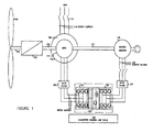
- variable speed wind turbine generator system is broadly shown in Fig. 1 .
- the variable speed system comprises one or more rotor blades (101) and a rotor hub which is connected to a drive train.
- the drive train mainly comprises a turbine shaft (102), a gearbox (103), a rotor shaft (104), and a doubly fed induction generator (105).
- the stator of the doubly fed induction generator (110) can be connected to the grid by using one or more contactors or circuit breakers (115).
- the system also comprises an exciter machine (112) such as an asynchronous machine, a DC machine, a synchronous (e.g.
- the exciter machine (112) can be coupled to the drive train by way of a shaft (113) connected on one end to the exciter machine and connected at the other end to the rotor of the DFIG (110, 111).
- the exciter machine is also connected to two active electronic power converters (122, 125) joined by a DC link Bus (124) (i.e. a back to back converter) with one of the AC side connected to the rotor circuit of the doubly fed induction generator and the other AC side connected to the exciter machine (112).
- a converter control unit (CCU) (100) carries out the power regulation of the doubly fed induction generator and the exciter machine.
- the system comprises filters such a dV/dt filter (120) which is connected to the rotor circuit of the doubly fed induction generator in order to protect it against abrupt voltage variations produced by the active switches of the power electronic converter.
- a dV/dt filter (127) is connected between the electronic power converter and the exciter machine.
- a further aspect of this exemplary embodiment is that there is no power converter connected to the grid.
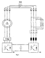
- Fig. 2 a classic doubly fed induction system is shown.
- the power converter (201) is connected to the grid, so grid fluctuations affect it.
- the power converter (125) is connected to the exciter machine, so it may work with a stable voltage, totally independent of the grid voltage.
- FIG. 3 An equivalent electrical circuit of an asynchronous machine is shown in Fig. 3 which includes such electrical parameters: the impedance of the grid and the profile of the voltage disturbance: slew rate, depth and instant. So, in this exemplary embodiment of the present invention, during this first transition, the exciter machine converts the electrical energy due to the generator demagnetizing into mechanical energy.
- the magnetizing branch (305) of the asynchronous machine (110) is going to try to keep the flux in the machine.
- This flux can not change instantaneously so it will appear as a differential voltage (309) between the grid voltage (308) and the magnetizing voltage (307) in the machine.
- This voltage (309) is proportional to the flux and the rotational speed.
- This differential voltage (309) will generate an over current in the stator, only limited by the stator leakage inductance (302) and the stator resistance (301). Due to the relation between the stator and the rotor, rather similar to the relation between the primary and the secondary in a transformer, the affect of the transition in the stator currents also appears in the rotor currents.
- the rotor of the generator is electrically connected to an electronic power converter. So, rotor currents during this transition, due to the generator demagnetizing, flow from the rotor to the DC Bus System through the power electronic converter.
- the grid side converter is not able to evacuate this energy because the grid residual voltage is reduced, so the DC voltage rises and the power electronic elements can be damaged.
- the operation has two processes. These processes may occur at the same time but will be explained separately for a better understanding:
- the exciter side converter (125) maintains its energy evacuation capacity because the voltage at the exciter machine terminals (129) are maintained stable or at least in a working band range. This voltage depends mainly on the speed, so stability is guaranteed by the drive train inertia, so the eventual speed fluctuations when a low voltage event occurs need not be significant in order to drastically change the voltage.
- the energy due to the demagnetizing of the doubly fed generator (110) during the low voltage event flows through the converters (122, 125) and the exciter machine (112), and is converted into mechanical energy. So, all the energy is transferred to the drive train.
- rotor currents (121) flow to the DC Bus system (124) through the rotor side converter (122, 202).
- the exciter side converter (125) could work at its maximal current capacity, keeping the BUS voltage in control at all times. This current limit is calculated by the main control unit taking charge of the operating working conditions.
- the converter (125) When the exciter voltage (129) is maintained in a stable condition, the converter (125) has a large capacity for energy evacuation. This energy is sent to the exciter which will store it as kinetic energy. So, providing this maximum capacity allows this first transition to be reduced to some milliseconds.
- Fig. 6 shows a typical profile for a grid fault
- the stator, rotor and exciter side converter currents (801), (802), (803) present an electrical evolution which is shown in Fig. 8 .
- the exciter side converter operates at its maximum current capacity during the approximately first 50 milliseconds in order to evacuate all the energy due to the generator demagnetizing.
- the main control unit makes the converter (125) work at this maximum current. The time working at this current can be varied depending on the low event fault characteristic and on the electrical system parameters.
- the oscillation that appears in the currents corresponds to the generator mechanical rotating frequency.
- the exciter side converter current (803) approaches zero once the generator is completely demagnetized.
- the rotor side converter tries to generate the nominal reactive current according to a typical specification. So, the final medium values of the stator and rotor currents correspond to the system nominal current conditions.
- the oscillations are deadened by control as it will be explained later.
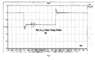
- the effect of this reactive current generation can be seen in Fig. 7 , where the stator voltage is shown. In approximately the first 25 milliseconds, the stator voltage drops 50%, and due to the grid support strategy, generating reactive current, the stator voltage rises to 65% with respect to the nominal value.
- a grid support strategy, supplying reactive current to the grid has been explained but other control strategies could be taken during the grind event.
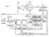
- the exciter side converter (125) operation is controlled by the main control unit (100) which regulates how the energy is evacuated to the exciter machine by controlling the active switches of the power electronic converter.
- Fig. 4 shows how the switches of the power converter (125) are controlled.
- low voltage algorithm detection and the maximum instantaneous current calculation available by the switches set by the DC Bus regulator (407) are used by the control system in the main control unit. This low voltage algorithm is based on the measured stator and rotor currents.
- the main control unit (100) establishes the maximum current that may be supplied to the switches of the converter (125) based on the semiconductor temperature limit, the switching frequency and other parameters. In one exemplary embodiment, the switching frequency could be variable.
- the DC Bus regulator (407) establishes a Sp_IEq which is the real current to be transferred to the exciter machine (112). In one exemplary embodiment this Sp_IEq is the maximum current available by the converter (125).
- the main control unit (100) establishes the time the exciter side converter (125) is working at its maximum current. In one exemplary embodiment, this is fixed and could be fixed and calculated by the main control unit. In one exemplary embodiment, this time could be variable and it is going to depend on the electrical system variables: Av_Ubus, rotor current (121) and stator current (118) and other variables. In one exemplary embodiment the following criteria is met,
- the rotor system will depend on the rotor currents on one side and on the magnetizing current with a frequency dependency on the rotor speed on the other side.
- the current regulation loops must detect these oscillations during the fault in order to keep the system under controlled. Once the control system detects these oscillations, it must try to reduce these oscillations to minimize the time of this transition and to carry the system into the conditions required by the different normative.
- this second process could begin some milliseconds after the first process has started.
- the main control unit decides when this second process must begin.
- a grid support strategy supplying reactive current or reactive power to the grid may be used.
- a grid support strategy supplying real current or real current to the grid may be used.
- a mixed control strategy may be used, wherein real and reactive current or real and reactive power may be supplied to the grid.
- Further information related to an exemplary embodiment of the present invention is the use of the exciter machine (112) as a power supply to generate different stable supplies.
- the voltage (129) generated by the exciter depends on the rotational speed, so when the system reaches a certain speed the voltage generated by the exciter generator is enough to generate the power supplies (502), (508), shown in Fig. 5 , required by the system.
- the system has two AC/DC systems (503) (502) based on semiconductors which generate two different DC Voltage supplies. Some diodes (509) (510) are placed at the DC output in order to decouple the two voltage sources (AC/DC systems (502), (503)).
- the system (502) will generate a voltage V2 and the system (503) will generate a voltage V1. So, the DC Voltage supply will be equal to the larger of V1 and V2.
- V1 is a slightly larger than V2.
- auxiliary power supply systems can be connected in order to generate the independent auxiliary supplies required for the system.
- auxiliary power supply systems are DC/DC (507) or DC/AC (505) systems and are based on semiconductors, passive elements and other electrical elements.
- some switches or contactors (504) could be placed at the input of the DC/DC or DC/AC systems in order to isolate each system.
- the auxiliary power supply process has different steps:
- the switch or contactor 501 may be kept closed.
Landscapes
- Engineering & Computer Science (AREA)
- Power Engineering (AREA)
- Control Of Eletrric Generators (AREA)
Applications Claiming Priority (2)
| Application Number | Priority Date | Filing Date | Title |
|---|---|---|---|
| US11/618,211 US7622815B2 (en) | 2006-12-29 | 2006-12-29 | Low voltage ride through system for a variable speed wind turbine having an exciter machine and a power converter not connected to the grid |
| EP07825244A EP2095497B1 (fr) | 2006-12-29 | 2007-04-24 | Système basse tension à période de grâce pour éolienne à vitesse variable avec excitatrice et convertisseur de puissance sans raccordement au réseau |
Related Parent Applications (1)
| Application Number | Title | Priority Date | Filing Date |
|---|---|---|---|
| EP07825244.2 Division | 2007-04-24 |
Publications (2)
| Publication Number | Publication Date |
|---|---|
| EP2424104A1 true EP2424104A1 (fr) | 2012-02-29 |
| EP2424104B1 EP2424104B1 (fr) | 2013-08-28 |
Family
ID=38969978
Family Applications (2)
| Application Number | Title | Priority Date | Filing Date |
|---|---|---|---|
| EP11188871.5A Not-in-force EP2424104B1 (fr) | 2006-12-29 | 2007-04-24 | Système de fonctionnement pendant un baisse de tension pour éolienne à vitesse variable dotée d'une machine d'excitateur et convertisseur d'alimentation non connecté au réseau |
| EP07825244A Active EP2095497B1 (fr) | 2006-12-29 | 2007-04-24 | Système basse tension à période de grâce pour éolienne à vitesse variable avec excitatrice et convertisseur de puissance sans raccordement au réseau |
Family Applications After (1)
| Application Number | Title | Priority Date | Filing Date |
|---|---|---|---|
| EP07825244A Active EP2095497B1 (fr) | 2006-12-29 | 2007-04-24 | Système basse tension à période de grâce pour éolienne à vitesse variable avec excitatrice et convertisseur de puissance sans raccordement au réseau |
Country Status (9)
| Country | Link |
|---|---|
| US (1) | US7622815B2 (fr) |
| EP (2) | EP2424104B1 (fr) |
| JP (1) | JP5014437B2 (fr) |
| CN (1) | CN101569086B (fr) |
| AU (1) | AU2007343120B2 (fr) |
| CA (2) | CA2853359A1 (fr) |
| ES (2) | ES2402219T3 (fr) |
| MX (1) | MX2009007076A (fr) |
| WO (1) | WO2008084284A1 (fr) |
Cited By (2)
| Publication number | Priority date | Publication date | Assignee | Title |
|---|---|---|---|---|
| CN103944188A (zh) * | 2014-04-25 | 2014-07-23 | 广东工业大学 | 一种针对含Crowbar装置的双馈风电机组低电压穿越性能改进方法 |
| EP2910739A1 (fr) * | 2014-02-24 | 2015-08-26 | Rolls-Royce plc | Générateur de puissance électrique pour un moteur à turbine à gaz |
Families Citing this family (67)
| Publication number | Priority date | Publication date | Assignee | Title |
|---|---|---|---|---|
| US7643928B2 (en) * | 2004-01-05 | 2010-01-05 | Bombardier Transportation Gmbh | System and method for controlling the speed of a gas turbine engine |
| US7511446B2 (en) * | 2005-08-05 | 2009-03-31 | Tm Ge Automation Systems Llc | System and method for starting a wound rotor motor |
| ES2296483B1 (es) * | 2005-11-21 | 2009-03-01 | Ingeteam Technology, S.A. | Un sistema de control y proteccion ante faltas simetricas y asimetricas, para generadores de tipo asincrono. |
| US7425771B2 (en) * | 2006-03-17 | 2008-09-16 | Ingeteam S.A. | Variable speed wind turbine having an exciter machine and a power converter not connected to the grid |
| EP2123908A4 (fr) * | 2006-12-22 | 2012-03-14 | Wind To Power System S L | Générateur asynchrone à double alimentation |
| US7622815B2 (en) * | 2006-12-29 | 2009-11-24 | Ingeteam Energy, S.A. | Low voltage ride through system for a variable speed wind turbine having an exciter machine and a power converter not connected to the grid |
| DE102007014728A1 (de) * | 2007-03-24 | 2008-10-02 | Woodward Seg Gmbh & Co. Kg | Verfahren und Vorrichtung zum Betrieb einer doppeltgespeisten Asynchronmaschine bei transienten Netzspannungsänderungen |
| DE102008034532A1 (de) * | 2008-02-20 | 2009-08-27 | Repower Systems Ag | Windkraftanlage mit Umrichterregelung |
| DE102008017715A1 (de) * | 2008-04-02 | 2009-10-15 | Nordex Energy Gmbh | Verfahren zum Betreiben einer Windenergieanlage mit einer doppelt gespeisten Asynchronmaschine sowie Windenergieanlage mit einer doppelt gespeisten Asynchronmaschine |
| US7977925B2 (en) * | 2008-04-04 | 2011-07-12 | General Electric Company | Systems and methods involving starting variable speed generators |
| DE102008037449B4 (de) * | 2008-10-14 | 2010-10-14 | Kenersys Gmbh | Windenergieanlage |
| US7786608B2 (en) * | 2008-11-17 | 2010-08-31 | General Electric Company | Protection system for wind turbine |
| CN101478244B (zh) * | 2009-01-12 | 2010-12-01 | 浙江大学 | 一种风力发电用电压跌落发生器 |
| EP2386137B1 (fr) * | 2009-01-12 | 2019-03-13 | Vestas Wind Systems A/S | Module convertisseur de puissance reconfigurable |
| CN101800510B (zh) * | 2009-02-10 | 2013-09-18 | 株式会社日立制作所 | 风力发电系统 |
| AU2009340724A1 (en) * | 2009-02-20 | 2010-08-26 | Mitsubishi Heavy Industries, Ltd. | Wind turbine generator |
| US8912672B2 (en) | 2009-05-20 | 2014-12-16 | Cummins Power Generator IP, Inc. | Control of an engine-driven generator to address transients of an electrical power grid connected thereto |
| CN101566672B (zh) * | 2009-06-01 | 2011-11-30 | 浙江海得新能源有限公司 | 模拟电网跌落的实验方法 |
| ES2360167B1 (es) * | 2009-08-10 | 2012-05-08 | Ingeteam Technology, S.A. | Método para el control de un sistema de conversión de energia |
| WO2011018527A2 (fr) * | 2009-08-14 | 2011-02-17 | Suzlon Energy Gmbh | Système générateur asynchrone et éolienne à système générateur asynchrone |
| US8227929B2 (en) * | 2009-09-25 | 2012-07-24 | General Electric Company | Multi-use energy storage for renewable sources |
| CN101789604B (zh) * | 2010-03-10 | 2012-03-28 | 深圳市禾望电气有限公司 | 一种判断电网电压跌落严重程度的方法 |
| EP2577860B1 (fr) * | 2010-05-27 | 2018-09-19 | Vestas Wind Systems A/S | Convertisseur de puissance haute tension |
| US8018083B2 (en) * | 2010-08-05 | 2011-09-13 | General Electric Company | HVDC connection of wind turbine |
| NZ607114A (en) | 2010-09-28 | 2014-10-31 | Siemens Ag | Power oscillation damping by a converter-based power generation device |
| ES2480276T3 (es) * | 2010-10-28 | 2014-07-25 | Vestas Wind Systems A/S | Un generador de turbina eólica |
| US8067847B1 (en) * | 2010-12-16 | 2011-11-29 | General Electric Company | Variable speed machine assembly and method for making the same |
| CN102055207B (zh) * | 2010-12-16 | 2012-08-01 | 南京飓能电控自动化设备制造有限公司 | 低电压穿越智能功率控制单元及其应用 |
| US8866340B2 (en) * | 2011-05-04 | 2014-10-21 | King Fahd University Of Petroleum And Minerals | Supercapacitor-based grid fault ride-through system |
| CN102810875B (zh) * | 2011-05-30 | 2014-10-22 | 通用电气公司 | 使用变流器进行能量转换的系统及其运作方法 |
| DK2532889T3 (da) * | 2011-06-06 | 2014-11-24 | Alstom Renewable Technologies | Vindmølle og fremgangsmåde til drift af vindmølle |
| CN102901919B (zh) | 2011-07-29 | 2015-02-04 | 台达电子企业管理(上海)有限公司 | 双馈式感应发电系统及其有源撬棍电路的自我测试方法 |
| CN104025413B (zh) | 2011-10-28 | 2018-06-26 | 通用电气公司 | 用于确定和响应电网故障事件类型的系统和方法 |
| WO2013060024A1 (fr) | 2011-10-28 | 2013-05-02 | General Electric Company | Systèmes et procédés destinés à rétablir un convertisseur après un événement de défaut dans un réseau |
| DK177555B1 (en) * | 2011-11-04 | 2013-10-07 | Envision Energy Denmark Aps | Wind Turbine with Additional Rotor Moment of Inertia |
| JP5942393B2 (ja) * | 2011-11-18 | 2016-06-29 | 株式会社日立製作所 | 回転電機システムまたは風力発電システム。 |
| CN103208960A (zh) * | 2012-01-16 | 2013-07-17 | 台达电子企业管理(上海)有限公司 | 一种励磁控制电路及其电励磁风电系统 |
| US8896261B2 (en) * | 2012-03-15 | 2014-11-25 | Hitachi, Ltd. | Doubly-fed generator and doubly-fed electric machine |
| US9041234B2 (en) * | 2012-03-26 | 2015-05-26 | Rockwell Automation Technologies, Inc. | Double fed induction generator (DFIG) converter and method for improved grid fault ridethrough |
| CN103378783A (zh) | 2012-04-16 | 2013-10-30 | 台达电子企业管理(上海)有限公司 | 一种励磁控制电路、控制方法及其电励磁风电系统 |
| TWI488425B (zh) * | 2012-07-16 | 2015-06-11 | Univ Nat Sun Yat Sen | 風力發電系統及其激磁式同步發電機的控制方法 |
| CN102790404A (zh) * | 2012-07-31 | 2012-11-21 | 许继集团有限公司 | 具备低电压穿越功能的双馈型风电机组 |
| CN102819221B (zh) * | 2012-08-08 | 2016-05-25 | 中国电力科学研究院 | 风电机组低电压穿越特性联合仿真模型及其联合仿真方法 |
| CN102916446B (zh) * | 2012-11-09 | 2014-10-01 | 南京飓能电控自动化设备制造有限公司 | 一种异步风力发电机组电控系统 |
| CN103078565B (zh) * | 2012-12-25 | 2016-02-03 | 北京金风科创风电设备有限公司 | 发电机制动设备 |
| US9343991B2 (en) * | 2013-01-18 | 2016-05-17 | General Electric Company | Current balance control for non-interleaved parallel bridge circuits in power converter |
| FR3002384B1 (fr) * | 2013-02-21 | 2016-08-19 | Valeo Systemes De Controle Moteur | Architecture electrique pour la conversion d'une tension continue en une tension alternative, et reciproquement |
| US9148022B2 (en) * | 2013-09-17 | 2015-09-29 | King Fahd University Of Petroleum And Minerals | Wind turbine permanent magnet synchronous generator (WT-PMSG) system |
| US9577557B2 (en) * | 2013-10-18 | 2017-02-21 | Abb Schweiz Ag | Turbine-generator system with DC output |
| US10050433B2 (en) | 2014-12-11 | 2018-08-14 | General Electric Company | Power generation system and method with resistive braking capability |
| CN104459540B (zh) * | 2014-12-15 | 2017-02-22 | 云南电网有限责任公司电网规划研究中心 | 一种无电网冲击的双馈风力发电机组低电压穿越功能的检测方法 |
| CN105790298B (zh) * | 2014-12-23 | 2019-03-12 | 台达电子工业股份有限公司 | 风力发电控制装置及风力发电系统 |
| CN104795835B (zh) * | 2015-03-26 | 2017-02-01 | 同济大学 | 一种双馈风电变流器开关频率的控制方法及系统 |
| GB201511033D0 (en) * | 2015-05-19 | 2015-08-05 | Rolls Royce Plc | Aircraft electrical network |
| US9705440B2 (en) * | 2015-07-16 | 2017-07-11 | Hamilton Sundstrand Corporation | Fault tolerant electric power generating system |
| CN105322840B (zh) * | 2015-11-19 | 2018-04-17 | 广东上水能源科技有限公司 | 可柔性运行的冗余型无刷双馈电机调速系统 |
| US10107260B2 (en) * | 2015-11-19 | 2018-10-23 | General Electric Company | Wind turbine auxiliary circuit control |
| AT518130A1 (de) * | 2015-12-29 | 2017-07-15 | Ge Jenbacher Gmbh & Co Og | Genset |
| CN105515485B (zh) * | 2016-02-04 | 2018-03-02 | 南京工程学院 | 一种电流频域解析的双馈风力发电机撬棒电阻整定方法 |
| US9847733B2 (en) | 2016-05-12 | 2017-12-19 | Rockwell Automation Technologies, Inc. | Power conversion system with DC bus regulation for abnormal grid condition ride through |
| GB2554954B (en) * | 2016-10-17 | 2018-11-21 | Zhong Qingchang | Operating doubly-fed induction generators as virtual synchronous generators |
| EP3505753A1 (fr) * | 2017-12-29 | 2019-07-03 | Acciona Windpower, S.A. | Procédé de fonctionnement de machines électriques |
| US10742149B1 (en) * | 2019-04-22 | 2020-08-11 | General Electric Company | System and method for reactive power control of a wind turbine by varying switching frequency of rotor side converter |
| EP3742600A1 (fr) | 2019-05-22 | 2020-11-25 | Siemens Gamesa Renewable Energy Innovation & Technology, S.L. | Système et procédé de commande pour convertisseur latéral de rotor d'un générateur à induction à double alimentation dans une éolienne |
| CN110445181B (zh) * | 2019-09-03 | 2021-03-23 | 中国石油大学(华东) | 一种通过调制和母线下垂实现双馈风机低电压穿越的方法 |
| EP3954896A1 (fr) * | 2020-08-14 | 2022-02-16 | Wobben Properties GmbH | Amortissement des balancements dans les éoliennes |
| CN117200360B (zh) * | 2023-09-13 | 2024-03-12 | 山东大学 | 自同步电压源型双馈风电机组高低电压穿越控制方法及系统 |
Citations (7)
| Publication number | Priority date | Publication date | Assignee | Title |
|---|---|---|---|---|
| WO2004040748A1 (fr) | 2002-11-01 | 2004-05-13 | Vestas Wind Systems A/S | Agencement de circuit pour systeme d'eolienne a vitesse variable comprenant une generateur d'induction a double alimentation et un convertisseur en opposition |
| WO2004070936A1 (fr) | 2003-02-07 | 2004-08-19 | Vestas Wind Systems A/S | Procede de commande d'un aerogenerateur connecte a un reseau electrique au cours de pannes de reseau et appareil de mise en oeuvre dudit procede |
| WO2004098261A2 (fr) | 2003-05-02 | 2004-11-18 | Xantrex Technology Inc. | Systeme de commande de generateur d'induction a double alimentation |
| US6921985B2 (en) | 2003-01-24 | 2005-07-26 | General Electric Company | Low voltage ride through for wind turbine generators |
| WO2005113964A1 (fr) * | 2004-05-18 | 2005-12-01 | Nordex Energy Gmbh | Installation eolienne pourvue d'un generateur auxiliaire, et son procede de commande |
| US20060016388A1 (en) | 2002-06-28 | 2006-01-26 | Kopin Corporation | Domain epitaxy for thin film growth |
| US7102247B2 (en) | 2002-01-29 | 2006-09-05 | Vestas Wind Systems A/S | Circuit arrangement and methods for use in a wind energy installation |
Family Cites Families (42)
| Publication number | Priority date | Publication date | Assignee | Title |
|---|---|---|---|---|
| US4297076A (en) | 1979-06-08 | 1981-10-27 | Lockheed Corporation | Wind turbine |
| US4400659A (en) * | 1980-05-30 | 1983-08-23 | Benjamin Barron | Methods and apparatus for maximizing and stabilizing electric power derived from wind driven source |
| US4994684A (en) * | 1989-01-30 | 1991-02-19 | The State Of Oregon Acting By And Through The State Board Of Higher Education On Behalf Of Oregon State University | Doubly fed generator variable speed generation control system |
| US5028804A (en) * | 1989-06-30 | 1991-07-02 | The State Of Oregon Acting By And Through The State Board Of Higher Education On Behalf Of Oregon State University | Brushless doubly-fed generator control system |
| US5083039B1 (en) | 1991-02-01 | 1999-11-16 | Zond Energy Systems Inc | Variable speed wind turbine |
| US5798631A (en) * | 1995-10-02 | 1998-08-25 | The State Of Oregon Acting By And Through The State Board Of Higher Education On Behalf Of Oregon State University | Performance optimization controller and control method for doubly-fed machines |
| US6137187A (en) | 1997-08-08 | 2000-10-24 | Zond Energy Systems, Inc. | Variable speed wind turbine generator |
| US6600240B2 (en) | 1997-08-08 | 2003-07-29 | General Electric Company | Variable speed wind turbine generator |
| US6420795B1 (en) | 1998-08-08 | 2002-07-16 | Zond Energy Systems, Inc. | Variable speed wind turbine generator |
| DE29715249U1 (de) | 1997-08-25 | 1998-12-24 | Institut für Solare Energieversorgungstechnik Verein an der Universität Gesamthochschule Kassel eV, 34119 Kassel | Windenergieanlage |
| DK199901436A (da) | 1999-10-07 | 2001-04-08 | Vestas Wind System As | Vindenergianlæg |
| US6274945B1 (en) * | 1999-12-13 | 2001-08-14 | Capstone Turbine Corporation | Combustion control method and system |
| AU2001274396A1 (en) * | 2000-05-23 | 2001-12-03 | Vestas Wind Systems A/S | Variable speed wind turbine having a matrix converter |
| US6448735B1 (en) * | 2001-04-26 | 2002-09-10 | Abb Automation Inc. | Controller for a wound rotor slip ring induction machine |
| DE10140793A1 (de) | 2001-08-20 | 2003-03-06 | Gen Electric | Einrichtung zum Verstellen des Rotorblattes eines Rotors einer Windkraftanlage |
| US6492801B1 (en) | 2001-08-21 | 2002-12-10 | Southern Company Services, Inc. | Method, apparatus, and system for real time reactive power output monitoring and predicting |
| DK174755B1 (da) | 2002-01-14 | 2003-10-20 | Vestas Wind Sys As | System til at forbinde en vindmøllegenerator med det elektriske forsyningsnet |
| US7015595B2 (en) * | 2002-02-11 | 2006-03-21 | Vestas Wind Systems A/S | Variable speed wind turbine having a passive grid side rectifier with scalar power control and dependent pitch control |
| JP2003264244A (ja) | 2002-03-08 | 2003-09-19 | Seiko Epson Corp | 半導体装置およびその製造方法 |
| DE10232423A1 (de) * | 2002-07-17 | 2004-01-29 | Ge Wind Energy Gmbh | Verfahren zum Betreiben einer Windenergieanlage und Windenergieanlage zum Ausführen derartiger Verfahren |
| FI115012B (fi) | 2003-03-06 | 2005-02-15 | Abb Oy | Menetelmä ja järjestely liukurengaskoneen yhteydessä |
| US7042110B2 (en) | 2003-05-07 | 2006-05-09 | Clipper Windpower Technology, Inc. | Variable speed distributed drive train wind turbine system |
| US7233129B2 (en) | 2003-05-07 | 2007-06-19 | Clipper Windpower Technology, Inc. | Generator with utility fault ride-through capability |
| FI115874B (fi) | 2003-05-27 | 2005-07-29 | Abb Oy | Menetelmä kaksoissyöttöisen koneen säätämiseksi |
| EP1499009B1 (fr) * | 2003-07-15 | 2007-10-31 | Gamesa Innovation & Technology, S.L. Unipersonal | Commande et protection d'un système générateur à induction à double alimentation |
| US7834472B2 (en) | 2003-08-07 | 2010-11-16 | Vestas Wind Systems A/S | Method of controlling a wind turbine connected to an electric utility grid during malfunction in said electric utility grid, control system, wind turbine and family hereof |
| US6924565B2 (en) | 2003-08-18 | 2005-08-02 | General Electric Company | Continuous reactive power support for wind turbine generators |
| AU2003270200B2 (en) | 2003-09-16 | 2009-09-10 | General Electric Company | Method for operating a frequency converter of a generator |
| PL1665495T3 (pl) | 2003-09-23 | 2012-07-31 | Aloys Wobben | Sposób obsługi elektrowni wiatrowej podczas zakłóceń w sieci elektrycznej |
| DE10344392A1 (de) | 2003-09-25 | 2005-06-02 | Repower Systems Ag | Windenergieanlage mit einem Blindleistungsmodul zur Netzstützung und Verfahren dazu |
| GB2410386A (en) | 2004-01-22 | 2005-07-27 | Areva T & D Uk Ltd | Controlling reactive power output |
| GB2411252A (en) | 2004-02-17 | 2005-08-24 | Areva T & D Uk Ltd | Controlling a generator with varying speed |
| CN1926742B (zh) | 2004-03-12 | 2011-05-25 | 通用电气公司 | 用于操作发电机变频器的方法以及具有根据这种方法操作的发电机的风能涡轮机 |
| US7038330B2 (en) | 2004-04-23 | 2006-05-02 | Rwe Piller Gmbh | Protection for wind power station |
| DE102004048339A1 (de) | 2004-10-01 | 2006-04-13 | Repower Systems Ag | Windenergeianlage mit Umrichtersteuerung und Verfahren zum Betrieb |
| WO2006069569A1 (fr) | 2004-12-28 | 2006-07-06 | Vestas Wind Systems A/S | Procede de commande d’une turbine eolienne connectee a un reseau electrique general |
| AU2005201713A1 (en) | 2005-04-26 | 2006-11-09 | Joanna Fredericks | Animal toileting system and method |
| US7514907B2 (en) | 2005-05-24 | 2009-04-07 | Satcon Technology Corporation | Device, system, and method for providing a low-voltage fault ride-through for a wind generator farm |
| US7276807B2 (en) * | 2006-01-19 | 2007-10-02 | General Electric Company | Wind turbine dump load system and method |
| CN100486093C (zh) * | 2006-03-08 | 2009-05-06 | 合肥阳光电源有限公司 | 风力发电用全功率型交直交变流器的控制结构 |
| US7425771B2 (en) * | 2006-03-17 | 2008-09-16 | Ingeteam S.A. | Variable speed wind turbine having an exciter machine and a power converter not connected to the grid |
| US7622815B2 (en) * | 2006-12-29 | 2009-11-24 | Ingeteam Energy, S.A. | Low voltage ride through system for a variable speed wind turbine having an exciter machine and a power converter not connected to the grid |
-
2006
- 2006-12-29 US US11/618,211 patent/US7622815B2/en not_active Expired - Fee Related
-
2007
- 2007-04-24 CA CA2853359A patent/CA2853359A1/fr active Pending
- 2007-04-24 CA CA2676120A patent/CA2676120C/fr active Active
- 2007-04-24 AU AU2007343120A patent/AU2007343120B2/en not_active Ceased
- 2007-04-24 EP EP11188871.5A patent/EP2424104B1/fr not_active Not-in-force
- 2007-04-24 ES ES07825244T patent/ES2402219T3/es active Active
- 2007-04-24 WO PCT/IB2007/002905 patent/WO2008084284A1/fr not_active Ceased
- 2007-04-24 EP EP07825244A patent/EP2095497B1/fr active Active
- 2007-04-24 CN CN200780048379.1A patent/CN101569086B/zh not_active Expired - Fee Related
- 2007-04-24 MX MX2009007076A patent/MX2009007076A/es active IP Right Grant
- 2007-04-24 ES ES11188871.5T patent/ES2436650T3/es active Active
- 2007-04-24 JP JP2009543529A patent/JP5014437B2/ja not_active Expired - Fee Related
Patent Citations (7)
| Publication number | Priority date | Publication date | Assignee | Title |
|---|---|---|---|---|
| US7102247B2 (en) | 2002-01-29 | 2006-09-05 | Vestas Wind Systems A/S | Circuit arrangement and methods for use in a wind energy installation |
| US20060016388A1 (en) | 2002-06-28 | 2006-01-26 | Kopin Corporation | Domain epitaxy for thin film growth |
| WO2004040748A1 (fr) | 2002-11-01 | 2004-05-13 | Vestas Wind Systems A/S | Agencement de circuit pour systeme d'eolienne a vitesse variable comprenant une generateur d'induction a double alimentation et un convertisseur en opposition |
| US6921985B2 (en) | 2003-01-24 | 2005-07-26 | General Electric Company | Low voltage ride through for wind turbine generators |
| WO2004070936A1 (fr) | 2003-02-07 | 2004-08-19 | Vestas Wind Systems A/S | Procede de commande d'un aerogenerateur connecte a un reseau electrique au cours de pannes de reseau et appareil de mise en oeuvre dudit procede |
| WO2004098261A2 (fr) | 2003-05-02 | 2004-11-18 | Xantrex Technology Inc. | Systeme de commande de generateur d'induction a double alimentation |
| WO2005113964A1 (fr) * | 2004-05-18 | 2005-12-01 | Nordex Energy Gmbh | Installation eolienne pourvue d'un generateur auxiliaire, et son procede de commande |
Non-Patent Citations (3)
| Title |
|---|
| ANSEL A ET AL: "Modelling and simulation of an autonomous variable speed micro hydropower station", MATHEMATICS AND COMPUTERS IN SIMULATION, ELSEVIER, AMSTERDAM, NL, vol. 71, 17 April 2006 (2006-04-17), pages 320 - 332, XP002467010, ISSN: 0378-4754, DOI: 10.1016/J.MATCOM.2006.02.011 * |
| BAUER P ET AL: "Evaluation of electrical systems for offshore windfarms", INDUSTRY APPLICATIONS CONFERENCE, 2000. CONFERENCE RECORD OF THE 2000 IEEE 8-12 OCTOBER 2000, PISCATAWAY, NJ, USA,IEEE, vol. 3, 8 October 2000 (2000-10-08), pages 1416 - 1423, XP010521303, ISBN: 0-7803-6401-5 * |
| KHATOUNIAN F ET AL: "Design of an Output LC Filter for a Doubly Fed Induction Generator Supplying Non-linear Loads for Aircraft Applications", INDUSTRIAL ELECTRONICS, 2004 IEEE INTERNATIONAL SYMPOSIUM ON AJACCIO, FRANCE 04-07 MAY 2004, PISCATAWAY, NJ, USA,IEEE, 4 May 2004 (2004-05-04), pages 1093 - 1098, XP010874479, ISBN: 0-7803-8304-4 * |
Cited By (3)
| Publication number | Priority date | Publication date | Assignee | Title |
|---|---|---|---|---|
| EP2910739A1 (fr) * | 2014-02-24 | 2015-08-26 | Rolls-Royce plc | Générateur de puissance électrique pour un moteur à turbine à gaz |
| US9729096B2 (en) | 2014-02-24 | 2017-08-08 | Rolls-Royce Plc | Electrical power generator for a gas turbine engine |
| CN103944188A (zh) * | 2014-04-25 | 2014-07-23 | 广东工业大学 | 一种针对含Crowbar装置的双馈风电机组低电压穿越性能改进方法 |
Also Published As
| Publication number | Publication date |
|---|---|
| WO2008084284A1 (fr) | 2008-07-17 |
| CN101569086B (zh) | 2012-09-26 |
| CA2676120C (fr) | 2015-04-21 |
| ES2402219T3 (es) | 2013-04-29 |
| CA2853359A1 (fr) | 2008-07-17 |
| CA2676120A1 (fr) | 2008-07-17 |
| MX2009007076A (es) | 2009-07-10 |
| CN101569086A (zh) | 2009-10-28 |
| ES2436650T3 (es) | 2014-01-03 |
| EP2424104B1 (fr) | 2013-08-28 |
| JP5014437B2 (ja) | 2012-08-29 |
| US20080157529A1 (en) | 2008-07-03 |
| AU2007343120A1 (en) | 2008-07-17 |
| JP2010515417A (ja) | 2010-05-06 |
| EP2095497A1 (fr) | 2009-09-02 |
| US7622815B2 (en) | 2009-11-24 |
| EP2095497B1 (fr) | 2013-01-16 |
| AU2007343120B2 (en) | 2011-02-03 |
Similar Documents
| Publication | Publication Date | Title |
|---|---|---|
| US7622815B2 (en) | Low voltage ride through system for a variable speed wind turbine having an exciter machine and a power converter not connected to the grid | |
| EP2315345B1 (fr) | Système à alimentation continue en cas de panne de réseau pour systèmes de conversion d'énergie éolienne basés sur des convertisseurs de source de courant | |
| EP1796259B1 (fr) | Unité de traitement de signal pour un système de dimensionnement | |
| EP1728304B1 (fr) | Procede de fonctionnement d'un convertisseur de frequence d'une generatrice et turbine eolienne comprenant une generatrice fonctionnant selon ce procede | |
| CN104604068B (zh) | 用于保护电机的系统和方法 | |
| Feltes et al. | High voltage ride-through of DFIG-based wind turbines | |
| CZ200529A3 (cs) | Zpusob cinnosti vetrné turbíny a vetrná turbína pro provádení tohoto zpusobu | |
| JP2006514523A5 (fr) | ||
| EP3672063B1 (fr) | Système et procédé de réglage de la tension d'une liaison cc d'un convertisseur de puissance d'un système d'alimentation électrique | |
| CA2802766A1 (fr) | Procede de commande de couple de generateur | |
| EP4333236A1 (fr) | Système et procédé de fonctionnement d'une source d'énergie renouvelable en mode de formation de réseau (fcm) en tant que machine synchrone virtuelle (vsm) avec émulation d'enroulement d'amortisseur | |
| Janning et al. | Next generation variable speed pump-storage power stations | |
| US8294430B2 (en) | Double-fed asynchronous generator and method for its operation | |
| Okedu et al. | Comparative study between two protection schemes for DFIG-based wind generator | |
| Feltes et al. | Fault ride-through of DFIG-based wind farms connected to the grid through VSC-based HVDC link | |
| Geske et al. | A New Method for Virtual Inertia Control in Wind Turbines with Doubly-Fed Induction Generators | |
| Mekala | Research Issues in DFIG Based Wind Energy System | |
| WO2025128122A1 (fr) | Système et procédé de réduction de déséquilibre de courant de réseau dans un système d'alimentation électrique | |
| JP2004222392A (ja) | 瞬時電圧変動対策用接続装置 | |
| Siddardha et al. | CONTROL AND INTERFACING OF DFIM-BASED WIND TURBINE GENARATOR UNDER VOLTAGE DIPS WITHOUT CROWBAR PROTECTION | |
| Boukhris et al. | Low voltage ride-through capability improvement of doubly fed induction generator using series connected damping resistances |
Legal Events
| Date | Code | Title | Description |
|---|---|---|---|
| 17P | Request for examination filed |
Effective date: 20111111 |
|
| AC | Divisional application: reference to earlier application |
Ref document number: 2095497 Country of ref document: EP Kind code of ref document: P |
|
| AK | Designated contracting states |
Kind code of ref document: A1 Designated state(s): AT BE BG CH CY CZ DE DK EE ES FI FR GB GR HU IE IS IT LI LT LU LV MC MT NL PL PT RO SE SI SK TR |
|
| AX | Request for extension of the european patent |
Extension state: AL BA HR MK RS |
|
| PUAI | Public reference made under article 153(3) epc to a published international application that has entered the european phase |
Free format text: ORIGINAL CODE: 0009012 |
|
| 17Q | First examination report despatched |
Effective date: 20120924 |
|
| RAP1 | Party data changed (applicant data changed or rights of an application transferred) |
Owner name: INGETEAM POWER TECHNOLOGY, S.A. |
|
| GRAP | Despatch of communication of intention to grant a patent |
Free format text: ORIGINAL CODE: EPIDOSNIGR1 |
|
| INTG | Intention to grant announced |
Effective date: 20130423 |
|
| GRAS | Grant fee paid |
Free format text: ORIGINAL CODE: EPIDOSNIGR3 |
|
| GRAA | (expected) grant |
Free format text: ORIGINAL CODE: 0009210 |
|
| AC | Divisional application: reference to earlier application |
Ref document number: 2095497 Country of ref document: EP Kind code of ref document: P |
|
| AK | Designated contracting states |
Kind code of ref document: B1 Designated state(s): AT BE BG CH CY CZ DE DK EE ES FI FR GB GR HU IE IS IT LI LT LU LV MC MT NL PL PT RO SE SI SK TR |
|
| REG | Reference to a national code |
Ref country code: GB Ref legal event code: FG4D |
|
| REG | Reference to a national code |
Ref country code: CH Ref legal event code: EP |
|
| REG | Reference to a national code |
Ref country code: AT Ref legal event code: REF Ref document number: 629801 Country of ref document: AT Kind code of ref document: T Effective date: 20130915 |
|
| REG | Reference to a national code |
Ref country code: IE Ref legal event code: FG4D |
|
| REG | Reference to a national code |
Ref country code: DE Ref legal event code: R096 Ref document number: 602007032606 Country of ref document: DE Effective date: 20131024 |
|
| REG | Reference to a national code |
Ref country code: ES Ref legal event code: FG2A Ref document number: 2436650 Country of ref document: ES Kind code of ref document: T3 Effective date: 20140103 |
|
| REG | Reference to a national code |
Ref country code: AT Ref legal event code: MK05 Ref document number: 629801 Country of ref document: AT Kind code of ref document: T Effective date: 20130828 |
|
| REG | Reference to a national code |
Ref country code: LT Ref legal event code: MG4D |
|
| REG | Reference to a national code |
Ref country code: NL Ref legal event code: VDEP Effective date: 20130828 |
|
| PG25 | Lapsed in a contracting state [announced via postgrant information from national office to epo] |
Ref country code: LT Free format text: LAPSE BECAUSE OF FAILURE TO SUBMIT A TRANSLATION OF THE DESCRIPTION OR TO PAY THE FEE WITHIN THE PRESCRIBED TIME-LIMIT Effective date: 20130828 Ref country code: IS Free format text: LAPSE BECAUSE OF FAILURE TO SUBMIT A TRANSLATION OF THE DESCRIPTION OR TO PAY THE FEE WITHIN THE PRESCRIBED TIME-LIMIT Effective date: 20131228 Ref country code: SE Free format text: LAPSE BECAUSE OF FAILURE TO SUBMIT A TRANSLATION OF THE DESCRIPTION OR TO PAY THE FEE WITHIN THE PRESCRIBED TIME-LIMIT Effective date: 20130828 Ref country code: PT Free format text: LAPSE BECAUSE OF FAILURE TO SUBMIT A TRANSLATION OF THE DESCRIPTION OR TO PAY THE FEE WITHIN THE PRESCRIBED TIME-LIMIT Effective date: 20131230 Ref country code: AT Free format text: LAPSE BECAUSE OF FAILURE TO SUBMIT A TRANSLATION OF THE DESCRIPTION OR TO PAY THE FEE WITHIN THE PRESCRIBED TIME-LIMIT Effective date: 20130828 Ref country code: CY Free format text: LAPSE BECAUSE OF FAILURE TO SUBMIT A TRANSLATION OF THE DESCRIPTION OR TO PAY THE FEE WITHIN THE PRESCRIBED TIME-LIMIT Effective date: 20130814 |
|
| REG | Reference to a national code |
Ref country code: NL Ref legal event code: VDEP Effective date: 20130828 |
|
| PG25 | Lapsed in a contracting state [announced via postgrant information from national office to epo] |
Ref country code: LV Free format text: LAPSE BECAUSE OF FAILURE TO SUBMIT A TRANSLATION OF THE DESCRIPTION OR TO PAY THE FEE WITHIN THE PRESCRIBED TIME-LIMIT Effective date: 20130828 Ref country code: SI Free format text: LAPSE BECAUSE OF FAILURE TO SUBMIT A TRANSLATION OF THE DESCRIPTION OR TO PAY THE FEE WITHIN THE PRESCRIBED TIME-LIMIT Effective date: 20130828 Ref country code: BE Free format text: LAPSE BECAUSE OF FAILURE TO SUBMIT A TRANSLATION OF THE DESCRIPTION OR TO PAY THE FEE WITHIN THE PRESCRIBED TIME-LIMIT Effective date: 20130828 Ref country code: FI Free format text: LAPSE BECAUSE OF FAILURE TO SUBMIT A TRANSLATION OF THE DESCRIPTION OR TO PAY THE FEE WITHIN THE PRESCRIBED TIME-LIMIT Effective date: 20130828 Ref country code: PL Free format text: LAPSE BECAUSE OF FAILURE TO SUBMIT A TRANSLATION OF THE DESCRIPTION OR TO PAY THE FEE WITHIN THE PRESCRIBED TIME-LIMIT Effective date: 20130828 Ref country code: GR Free format text: LAPSE BECAUSE OF FAILURE TO SUBMIT A TRANSLATION OF THE DESCRIPTION OR TO PAY THE FEE WITHIN THE PRESCRIBED TIME-LIMIT Effective date: 20131129 |
|
| PG25 | Lapsed in a contracting state [announced via postgrant information from national office to epo] |
Ref country code: CY Free format text: LAPSE BECAUSE OF FAILURE TO SUBMIT A TRANSLATION OF THE DESCRIPTION OR TO PAY THE FEE WITHIN THE PRESCRIBED TIME-LIMIT Effective date: 20130828 |
|
| PG25 | Lapsed in a contracting state [announced via postgrant information from national office to epo] |
Ref country code: NL Free format text: LAPSE BECAUSE OF FAILURE TO SUBMIT A TRANSLATION OF THE DESCRIPTION OR TO PAY THE FEE WITHIN THE PRESCRIBED TIME-LIMIT Effective date: 20130828 Ref country code: RO Free format text: LAPSE BECAUSE OF FAILURE TO SUBMIT A TRANSLATION OF THE DESCRIPTION OR TO PAY THE FEE WITHIN THE PRESCRIBED TIME-LIMIT Effective date: 20130828 Ref country code: CZ Free format text: LAPSE BECAUSE OF FAILURE TO SUBMIT A TRANSLATION OF THE DESCRIPTION OR TO PAY THE FEE WITHIN THE PRESCRIBED TIME-LIMIT Effective date: 20130828 Ref country code: EE Free format text: LAPSE BECAUSE OF FAILURE TO SUBMIT A TRANSLATION OF THE DESCRIPTION OR TO PAY THE FEE WITHIN THE PRESCRIBED TIME-LIMIT Effective date: 20130828 Ref country code: DK Free format text: LAPSE BECAUSE OF FAILURE TO SUBMIT A TRANSLATION OF THE DESCRIPTION OR TO PAY THE FEE WITHIN THE PRESCRIBED TIME-LIMIT Effective date: 20130828 Ref country code: SK Free format text: LAPSE BECAUSE OF FAILURE TO SUBMIT A TRANSLATION OF THE DESCRIPTION OR TO PAY THE FEE WITHIN THE PRESCRIBED TIME-LIMIT Effective date: 20130828 |
|
| PG25 | Lapsed in a contracting state [announced via postgrant information from national office to epo] |
Ref country code: IT Free format text: LAPSE BECAUSE OF FAILURE TO SUBMIT A TRANSLATION OF THE DESCRIPTION OR TO PAY THE FEE WITHIN THE PRESCRIBED TIME-LIMIT Effective date: 20130828 |
|
| REG | Reference to a national code |
Ref country code: DE Ref legal event code: R097 Ref document number: 602007032606 Country of ref document: DE |
|
| PLBE | No opposition filed within time limit |
Free format text: ORIGINAL CODE: 0009261 |
|
| STAA | Information on the status of an ep patent application or granted ep patent |
Free format text: STATUS: NO OPPOSITION FILED WITHIN TIME LIMIT |
|
| PGFP | Annual fee paid to national office [announced via postgrant information from national office to epo] |
Ref country code: GB Payment date: 20140428 Year of fee payment: 8 |
|
| 26N | No opposition filed |
Effective date: 20140530 |
|
| PGFP | Annual fee paid to national office [announced via postgrant information from national office to epo] |
Ref country code: DE Payment date: 20140414 Year of fee payment: 8 Ref country code: FR Payment date: 20140417 Year of fee payment: 8 |
|
| REG | Reference to a national code |
Ref country code: DE Ref legal event code: R097 Ref document number: 602007032606 Country of ref document: DE Effective date: 20140530 |
|
| PG25 | Lapsed in a contracting state [announced via postgrant information from national office to epo] |
Ref country code: LU Free format text: LAPSE BECAUSE OF FAILURE TO SUBMIT A TRANSLATION OF THE DESCRIPTION OR TO PAY THE FEE WITHIN THE PRESCRIBED TIME-LIMIT Effective date: 20140424 Ref country code: MC Free format text: LAPSE BECAUSE OF FAILURE TO SUBMIT A TRANSLATION OF THE DESCRIPTION OR TO PAY THE FEE WITHIN THE PRESCRIBED TIME-LIMIT Effective date: 20130828 |
|
| REG | Reference to a national code |
Ref country code: CH Ref legal event code: PL |
|
| REG | Reference to a national code |
Ref country code: IE Ref legal event code: MM4A |
|
| PG25 | Lapsed in a contracting state [announced via postgrant information from national office to epo] |
Ref country code: LI Free format text: LAPSE BECAUSE OF NON-PAYMENT OF DUE FEES Effective date: 20140430 Ref country code: CH Free format text: LAPSE BECAUSE OF NON-PAYMENT OF DUE FEES Effective date: 20140430 |
|
| PG25 | Lapsed in a contracting state [announced via postgrant information from national office to epo] |
Ref country code: IE Free format text: LAPSE BECAUSE OF NON-PAYMENT OF DUE FEES Effective date: 20140424 |
|
| PGFP | Annual fee paid to national office [announced via postgrant information from national office to epo] |
Ref country code: ES Payment date: 20150224 Year of fee payment: 9 |
|
| REG | Reference to a national code |
Ref country code: DE Ref legal event code: R119 Ref document number: 602007032606 Country of ref document: DE |
|
| GBPC | Gb: european patent ceased through non-payment of renewal fee |
Effective date: 20150424 |
|
| PG25 | Lapsed in a contracting state [announced via postgrant information from national office to epo] |
Ref country code: DE Free format text: LAPSE BECAUSE OF NON-PAYMENT OF DUE FEES Effective date: 20151103 Ref country code: GB Free format text: LAPSE BECAUSE OF NON-PAYMENT OF DUE FEES Effective date: 20150424 |
|
| REG | Reference to a national code |
Ref country code: FR Ref legal event code: ST Effective date: 20151231 |
|
| PG25 | Lapsed in a contracting state [announced via postgrant information from national office to epo] |
Ref country code: FR Free format text: LAPSE BECAUSE OF NON-PAYMENT OF DUE FEES Effective date: 20150430 |
|
| PG25 | Lapsed in a contracting state [announced via postgrant information from national office to epo] |
Ref country code: MT Free format text: LAPSE BECAUSE OF FAILURE TO SUBMIT A TRANSLATION OF THE DESCRIPTION OR TO PAY THE FEE WITHIN THE PRESCRIBED TIME-LIMIT Effective date: 20130828 |
|
| PG25 | Lapsed in a contracting state [announced via postgrant information from national office to epo] |
Ref country code: BG Free format text: LAPSE BECAUSE OF FAILURE TO SUBMIT A TRANSLATION OF THE DESCRIPTION OR TO PAY THE FEE WITHIN THE PRESCRIBED TIME-LIMIT Effective date: 20130828 |
|
| PG25 | Lapsed in a contracting state [announced via postgrant information from national office to epo] |
Ref country code: TR Free format text: LAPSE BECAUSE OF FAILURE TO SUBMIT A TRANSLATION OF THE DESCRIPTION OR TO PAY THE FEE WITHIN THE PRESCRIBED TIME-LIMIT Effective date: 20130828 Ref country code: HU Free format text: LAPSE BECAUSE OF FAILURE TO SUBMIT A TRANSLATION OF THE DESCRIPTION OR TO PAY THE FEE WITHIN THE PRESCRIBED TIME-LIMIT; INVALID AB INITIO Effective date: 20070424 |
|
| PG25 | Lapsed in a contracting state [announced via postgrant information from national office to epo] |
Ref country code: ES Free format text: LAPSE BECAUSE OF NON-PAYMENT OF DUE FEES Effective date: 20160425 |
|
| REG | Reference to a national code |
Ref country code: ES Ref legal event code: FD2A Effective date: 20181205 |