EP2425162B1 - Check valve - Google Patents
Check valve Download PDFInfo
- Publication number
- EP2425162B1 EP2425162B1 EP20100718469 EP10718469A EP2425162B1 EP 2425162 B1 EP2425162 B1 EP 2425162B1 EP 20100718469 EP20100718469 EP 20100718469 EP 10718469 A EP10718469 A EP 10718469A EP 2425162 B1 EP2425162 B1 EP 2425162B1
- Authority
- EP
- European Patent Office
- Prior art keywords
- check valve
- shut
- valve
- tab
- housing
- Prior art date
- Legal status (The legal status is an assumption and is not a legal conclusion. Google has not performed a legal analysis and makes no representation as to the accuracy of the status listed.)
- Active
Links
Images


Classifications
-
- F—MECHANICAL ENGINEERING; LIGHTING; HEATING; WEAPONS; BLASTING
- F16—ENGINEERING ELEMENTS AND UNITS; GENERAL MEASURES FOR PRODUCING AND MAINTAINING EFFECTIVE FUNCTIONING OF MACHINES OR INSTALLATIONS; THERMAL INSULATION IN GENERAL
- F16K—VALVES; TAPS; COCKS; ACTUATING-FLOATS; DEVICES FOR VENTING OR AERATING
- F16K15/00—Check valves
- F16K15/02—Check valves with guided rigid valve members
- F16K15/03—Check valves with guided rigid valve members with a hinged closure member or with a pivoted closure member
- F16K15/031—Check valves with guided rigid valve members with a hinged closure member or with a pivoted closure member the hinge being flexible
-
- F—MECHANICAL ENGINEERING; LIGHTING; HEATING; WEAPONS; BLASTING
- F16—ENGINEERING ELEMENTS AND UNITS; GENERAL MEASURES FOR PRODUCING AND MAINTAINING EFFECTIVE FUNCTIONING OF MACHINES OR INSTALLATIONS; THERMAL INSULATION IN GENERAL
- F16K—VALVES; TAPS; COCKS; ACTUATING-FLOATS; DEVICES FOR VENTING OR AERATING
- F16K15/00—Check valves
- F16K15/14—Check valves with flexible valve members
- F16K15/144—Check valves with flexible valve members the closure elements being fixed along all or a part of their periphery
-
- F—MECHANICAL ENGINEERING; LIGHTING; HEATING; WEAPONS; BLASTING
- F16—ENGINEERING ELEMENTS AND UNITS; GENERAL MEASURES FOR PRODUCING AND MAINTAINING EFFECTIVE FUNCTIONING OF MACHINES OR INSTALLATIONS; THERMAL INSULATION IN GENERAL
- F16K—VALVES; TAPS; COCKS; ACTUATING-FLOATS; DEVICES FOR VENTING OR AERATING
- F16K15/00—Check valves
- F16K15/14—Check valves with flexible valve members
- F16K15/148—Check valves with flexible valve members the closure elements being fixed in their centre
-
- Y—GENERAL TAGGING OF NEW TECHNOLOGICAL DEVELOPMENTS; GENERAL TAGGING OF CROSS-SECTIONAL TECHNOLOGIES SPANNING OVER SEVERAL SECTIONS OF THE IPC; TECHNICAL SUBJECTS COVERED BY FORMER USPC CROSS-REFERENCE ART COLLECTIONS [XRACs] AND DIGESTS
- Y10—TECHNICAL SUBJECTS COVERED BY FORMER USPC
- Y10T—TECHNICAL SUBJECTS COVERED BY FORMER US CLASSIFICATION
- Y10T137/00—Fluid handling
- Y10T137/7722—Line condition change responsive valves
- Y10T137/7837—Direct response valves [i.e., check valve type]
-
- Y—GENERAL TAGGING OF NEW TECHNOLOGICAL DEVELOPMENTS; GENERAL TAGGING OF CROSS-SECTIONAL TECHNOLOGIES SPANNING OVER SEVERAL SECTIONS OF THE IPC; TECHNICAL SUBJECTS COVERED BY FORMER USPC CROSS-REFERENCE ART COLLECTIONS [XRACs] AND DIGESTS
- Y10—TECHNICAL SUBJECTS COVERED BY FORMER USPC
- Y10T—TECHNICAL SUBJECTS COVERED BY FORMER US CLASSIFICATION
- Y10T137/00—Fluid handling
- Y10T137/7722—Line condition change responsive valves
- Y10T137/7837—Direct response valves [i.e., check valve type]
- Y10T137/7879—Resilient material valve
- Y10T137/7888—With valve member flexing about securement
-
- Y—GENERAL TAGGING OF NEW TECHNOLOGICAL DEVELOPMENTS; GENERAL TAGGING OF CROSS-SECTIONAL TECHNOLOGIES SPANNING OVER SEVERAL SECTIONS OF THE IPC; TECHNICAL SUBJECTS COVERED BY FORMER USPC CROSS-REFERENCE ART COLLECTIONS [XRACs] AND DIGESTS
- Y10—TECHNICAL SUBJECTS COVERED BY FORMER USPC
- Y10T—TECHNICAL SUBJECTS COVERED BY FORMER US CLASSIFICATION
- Y10T137/00—Fluid handling
- Y10T137/7722—Line condition change responsive valves
- Y10T137/7837—Direct response valves [i.e., check valve type]
- Y10T137/7879—Resilient material valve
- Y10T137/7888—With valve member flexing about securement
- Y10T137/7891—Flap or reed
- Y10T137/7892—With stop
Definitions
- the present invention relates to a check valve with a valve housing, on which a valve seat is formed, which is formed with respect to a flow direction as an inclined surface, and with a locking element, which has at least one planar locking tab of an elastically deformable material in a locked position abuts the valve seat and is lifted in an open position from the valve seat to allow the passage of fluid, wherein on the valve seat side facing away from the locking tab a stop element is arranged against which the locking tab can strike to the extent of lifting the locking tab of to limit the valve seat, wherein the blocking element has two locking tabs, which are aligned in a longitudinal section V-shaped.
- the present invention further relates to a fluid pump with a pump housing and a displaceably mounted therein piston, which forms a pressure chamber with the pump housing, wherein a suction port of the pump via a first check valve is connected to the pressure chamber and wherein the pressure chamber is connected via a second check valve to a pressure port of the pump.
- check valve is well known.
- a check valve is generally used to determine the direction of the flow of a fluid and is a directional control valve, which automatically blocks the passage of the fluid in one of the two flow directions.
- so-called ball check valves are known in which the blocking element is formed by a ball which is pressed by a spring in the valve seat.
- valve seat is arranged perpendicular to the flow direction and closed by a flap.
- the flap can be hung in particular at an upper area, so that it automatically enters the blocking position due to its own weight.
- Piston pumps are pumps for conveying fluids, wherein the fluid to be delivered is sucked through an inlet valve with the piston in a first cycle. It is then expelled through the outlet valve in a second cycle.
- a pump can also be referred to as a positive displacement pump.
- Circuits are undesirable. Further, this may also be undesirable if the fluid tends to crystallize out at standstill or to form lumps. This applies, for example, when using the fluid pump for pumping urea.
- Such pumps are used in urea injection systems as used in diesel engine exhaust emission control systems (so-called DNOX systems).
- the publication DE-U-20 2005 019 518 shows a device for venting a crankcase of an internal combustion engine, wherein the device comprises a generic check valve, which allows gas flow in a direction from the crankcase to an intake tract depending on the gas pressure on both sides of the check valve and blocks gas flow in a direction from the intake to the crankcase.
- the check valve consists of a valve tongue which rests in a closed position on a valve seat and which rests in a fully open state on a Ventilzonneanschlag.
- the stop element is designed as a conically expanding volume element in the flow direction, which fills the space defined between the locking tabs to at least 50%, in particular at least 80%.
- the above object is achieved in the fluid pump mentioned above in that the first and / or the second check valve is designed as a check valve according to the invention.
- the invention can also be formulated as a non-return valve with an oblique valve seat against which a locking tab made of elastically deformable material rests whose deflection is limited by a special stop element.
- the stop element can provide two inclined abutment surfaces for the two locking tabs. Furthermore, a dead space lying behind the locking tabs in the flow direction is reduced. As a result, there is less power loss and improved delivery.
- a valve opening is formed, which may include a plurality of individual openings, which are jointly closed by a locking tab.
- the locking tab Due to the formation of the locking tab of an elastically deformable material can be achieved that the locking tab is biased due to its own elasticity in the locked position. As a result, the lock position can also be achieved generally safely.
- the angle of the locking tab with respect to the longitudinal axis in the not yet installed state is greater than and in particular greater than the corresponding angle of the valve seat.
- the locking tabs can be securely biased into the locked position due to their own elasticity.
- the function of the check valve according to the invention is similar to the function of fish gills, which are also aerodynamically optimized due to evolution. Even with comparatively high operating frequencies of the check valve there is no flutter.
- the achievable high dynamics is further achieved in that the degree of lifting or the deflection of the locking tab is limited by the valve seat by the stop element. In other words, the opening angle of the locking tab can be limited. As a result, the actuation frequency can be increased because the locking tab can get back into the locked position faster. Since a valve opening is usually much smaller than the area of the locking tab, this can be achieved even without loss of the delivery rate.
- the check valve according to the invention is suitable for comparatively high actuation frequencies, for example for actuation frequencies of up to 20 Hz or even up to 60 or 70 Hz or even higher.
- a higher dynamics or a higher pump frequency of the piston can likewise be achieved.
- a stop surface of the stop element is aligned obliquely, such that the locking tab is also aligned obliquely in the open position.
- the locking tab in the open position lies flat against the stop surface.
- the locking tab in the opening position has a different angle than the corresponding stop surface.
- the locking tab in the opening position, can lie flat against the stop surface. In this way, selective pressure loads on the stop element facing the side of the locking tab can be avoided.
- the stop element extends in the flow direction approximately as far as the locking tab.
- the stop element may be part of the valve housing or attached to the valve housing as a separate component.
- the stop element is formed integrally with the blocking element.
- the number of components or the complexity of the valve housing can be reduced.
- a recess is formed in the region of the transition between the stop element and the locking tab, which serves to increase the mobility of the locking tab.
- the locking tab may have a certain thickness, which can provide a stable position of the locking tab in the locked position, even with a large valve opening in the valve seat.
- the mobility in the opening direction or closing direction can be increased by such a recess, which is formed at the proximal end of the locking tab.
- valve seats are also formed on the valve housing in the rule, which form in a corresponding manner in longitudinal section a V-shape.
- the valve thus includes two parallel check valves. In this way, the radial forces occurring can be compensated against each other. Therefore, this training is preferably also when the check valve is part of a movable system in the flow direction, for example, is arranged on a piston of a fluid pump.
- the two locking tabs are integrally connected. As a result, the number of components can be kept low.
- the stop element is arranged in the region between the locking tabs.
- the stop element may have both a stop surface for the one locking tab and a stop surface for the second locking tab. According to a further preferred embodiment, the stop element is arranged so that the locking tabs can not touch.
- the blocking element has a fastening portion, by means of which the blocking element is attached to the valve housing.
- the attachment can be done by means of screws, by gluing, by geometric form-fitting or other types of fastening.
- valve housing has a mounting recess, which is aligned transversely to the flow direction, wherein the mounting portion is inserted into the mounting recess to fix the locking element in the flow direction form-fitting manner to the valve housing.
- the blocking element has a bead extending transversely to the flow direction, which is inserted into a corresponding, transversely extending recess of the valve housing in order to achieve an axially positive connection.
- the attachment portion has a ring portion which is inserted into an annular mounting recess of the valve housing.
- the blocking element can be fixed without further measures in the radial direction of the valve housing.
- the ring section is connected to the locking tab via at least one longitudinal web section.
- the longitudinal web section is arranged in a longitudinally aligned recess of the valve housing.
- attachment portion of the locking element can be integrated, for example, in a cylinder contour of the valve housing, without the attachment portion projecting in the radial direction outwards relative to the cylinder contour.
- this embodiment is therefore suitable for the use of the check valve on a movable element such as a piston.
- the two locking tabs are connected to one another at a transverse web (for example in V-shape), the ends of which are each connected to the annular section via a longitudinal web section.
- This embodiment enables an axially stable connection between the locking tab and the ring portion.
- valve housing has a cylinder portion which has at least one longitudinal passage connected to the valve opening, wherein the valve seat is formed on an end face of the cylinder portion.
- This embodiment allows for a simple housing structure.
- the second pressure chamber can be formed for example by the cylinder portion and a second housing portion.
- the longitudinal channel preferably forms part of a first pressure chamber.
- the check valve can be integrated in a simple manner into a cylindrical piston, specifically on its end face.
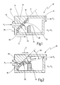
- a non-inventive embodiment of a check valve is generally designated 10.
- the check valve 10 has a valve housing 12.
- the valve housing separates a first pressure chamber 14, in which a fluid has a first fluid pressure P 1 , from a second pressure chamber 16, in which the fluid has a second pressure P 2 .
- valve housing 12 Inside the valve housing 12, a valve space is formed, which is connected to the second pressure chamber 16.
- the check valve establishes a flow direction S, via which fluid can pass from the first pressure chamber 14 into the second pressure chamber 16.
- the flow direction S is parallel to a longitudinal extent of the check valve 10.
- a side of the valve chamber facing the first pressure chamber 14 is designed as a valve seat 18.
- the valve seat 18 is formed as an inclined surface, which occupies an angle greater than 15 ° and smaller than 80 ° with respect to the flow direction S, in particular greater than 30 ° and less than 60 °, in the present case 45 °.
- valve opening 19 is formed, which is connected via a longitudinal channel 20 in the valve housing 12 with the first pressure chamber 14.
- the valve opening 19 can be a single valve opening or consist of a plurality of separate individual openings, which are connected to the first pressure chamber 14.
- the inclined surface of the valve seat 18 may be formed as a flat surface, as in Fig. 1 is shown. However, the inclined surface may also be formed as a curved surface, which is formed concave or convex, for example, in longitudinal section and / or in cross-section.
- a blocking element 22 of the check valve 10 is further arranged.
- the blocking element 22 is made of an elastically deformable material, in particular a plastic material and has a locking tab 24.
- the locking tab 24 is adapted in its shape to the valve seat 18, so in the present case is designed as a flat flap (but may be a curved flap).
- the blocking element 22 also has an integrally formed with the locking tab 24 mounting portion 26.
- the attachment portion 26 is fixed to the valve housing 12 in a rear area of the valve seat 18, as viewed in the flow direction S.
- fasteners 28 are used in Fig. 1 shown schematically.
- the fastening means may for example be formed by one or more screws, rivets or the like.
- the fastening means 28 may also be formed by a bond.
- the blocking element 22 is, as stated, formed from an elastic material and is attached via the attachment portion 26 to the valve housing 12 in such a way that a locking tab 24 rests against the valve seat 18 in a relaxed position (ie, not elastically deflected).
- a locking tab 24 rests against the valve seat 18 in a relaxed position (ie, not elastically deflected).
- Fig. 1 the check valve 10 is shown in a blocking position, in which the second pressure P 2 is greater than the first pressure P. 1 As a result, the locking tab 24 is pressed against the valve seat 18. The valve opening 19 is thus closed.
- Fig. 2 the check valve 10 is shown in an open position.
- the first pressure P 1 is greater than the second pressure P 2 (again, the eventual biasing force of the locking tab 24 may be included).
- a fluid in the first pressure space 14 pushes and deflects the locking tabs 24 away from the valve seat 18, as shown schematically at 32.
- the fluid 30, as shown by double arrows can flow from the first fluid space 14 into the second fluid space 16.
- the fluid 30 does not strike the frontal but obliquely on the first pressure chamber 14 facing side of the locking tab 24, so that it can be fluidly directed from the first fluid chamber 14 into the second fluid chamber 16.
- the barrier tab 24 is flowed obliquely or laterally, similar to gills of a fish.
- a high operating frequency can be achieved, for example, greater than 50 Hz, without fluttering of the blocking element occurs.
- the shape of the locking tab 24 may be further selected so that when the pressure is reversed to initiate a suction stroke, the locking tab is urged back toward the valve seat 18 (for example, by properly forming a forward end of the locking tab, as shown in FIG Fig. 2 is indicated schematically.
- a stop member 34 is adapted to limit the amount of lifting or the deflection 32 of the locking tab 24 relative to the valve seat 18, to an angle 36.
- the angle 36 may be in the range of a few degrees are up to 45 ° and is 30 ° in the illustrated embodiment. Preferably, however, the angle of maximum deflection 32 is less than 30 °.
- the stop element has a stop surface 35, which is preferably oriented obliquely, in such a way that the side facing away from the valve seat 18 of the locking tab 24 in the open position bears flat against it.
- the actuation frequency of the check valve can be further increased by the stop element 34. Because of the stop element can be prevented that the stop element is deflected to parallel to the flow direction or beyond. As a result, the blocking element can also be moved back from the opening position to the blocking position more quickly.
- Fig. 3 shows an inventive embodiment of a check valve, which has a valve housing 12 with a first housing part 40 and a second housing part 42, which are connected to each other, for example via a threaded engagement 44 or the like.
- the check valve 10 of the Fig. 3 a locking element 22, which includes two locking tabs 24A, 24B, which are preferably integrally connected to each other.
- the locking tabs 24A, 24B abut corresponding valve seats 18A, 18B of the first sub-housing 40, which are inclined opposite to the flow direction S in the opposite direction.
- the valve seats 18A, 18B and the barrier tabs 24A, 24B, respectively are V-shaped and include an angle ⁇ which is preferably greater than 40 ° and less than 150 °.
- Each of the valve seats 18A, 18B is associated with its own longitudinal channel 20, wherein the longitudinal channels 20 are each connected to the first pressure chamber 14.
- the longitudinal channels 20 are each connected to the first pressure chamber 14.
- a longitudinal channel 20 per locking tab 24 two longitudinal channels 20 are shown, so a longitudinal channel 20 per locking tab 24. However, it can also per locking tab 24 a plurality of longitudinal channels 20 (and corresponding valve openings) may be provided.
- the transverse web 48 is bead-shaped in longitudinal section and is inserted in the transverse direction (perpendicular to the plane of representation) in a mounting recess 50 of the first housing part 40.
- the blocking element 22 can be connected in a form-fitting manner to the first part housing 40 in the flow direction S without any further fastening means.
- the valve chamber connected to the second pressure chamber 16 is formed in this embodiment between the first and the second sub-housing 40, 42.
- the second valve housing 42 may include a conical surface 52, which tapers in the flow direction, towards the second pressure chamber 16 Flow of the fluid 30 are further optimized in the opening position in terms of fluidic aspects.
- a stop element 34 is shown, which is arranged between the two locking tabs 24A, 24B and limits the amount of maximum deflection of the locking tabs 24A, 24B. Furthermore, the stop element 34 is formed as a volume element which extends into the valve space and thus reduces the dead space of the check valve.
- Fig. 4 shows a further embodiment of a check valve according to the invention, which generally with respect to structure and function of the check valve of Fig. 3 equivalent.
- a first part housing 40 which has a cylinder portion 53.
- the blocking element 22 is fixed to the cylinder section 53.
- the check valve differs Fig. 4 from that of Fig. 3 by the manner of the formation of the attachment portion 26.
- the attachment portion is formed by a transverse web having a bead shape is in the embodiment of the Fig. 4 a fastening portion 26 is provided, which has a ring portion 56.
- the ring section 56 is received in an annular mounting recess 57 running around the cylinder section 53, so that the annular section 56 does not protrude in the radial direction relative to the outer contour of the cylinder section 53.
- the ring portion 56 is connected to the integrally connected locking tabs 24A, 24B via longitudinal web portions 58. More specifically, the attachment portion 26 has two longitudinal ridge portions 58 disposed on radially opposite sides of the cylinder portion 53, of which Figs Fig. 4 only one is shown. Due to the sectional view in Fig. 5 there is none of the longitudinal web sections 58 shown.
- the longitudinal web portions 58 are connected at their end facing away from the ring portion 56 with a respective radial end of a transverse web 48, which connects the locking tabs 24 A, 24 B together.
- One end of the cross bar 48 is in Fig. 4 designated 62.
- the arrangement of the check valve 10 is symmetrical with respect to a through the longitudinal axis of the cylinder portion 53 extending symmetry axis 60th
- Fig. 4 Longitudinal recesses on the outer periphery of the cylinder portion 53, in which the longitudinal web portions 58 are inserted. Therefore, the shut-off element 22 does not occur overall with respect to the outer contour of the cylinder section 53.
- Fig. 4 and 5 illustrated check valve in particular also for use as a linearly movable element, in particular as part of a piston of a fluid pump.
- the second valve housing is preferably formed by a cylinder within which the piston is guided.
- the stopper member 34 is integrally formed with the locking member 22 in this embodiment and extends conically widening between the two locking tabs 24A, 24B.
- the maximum opening angle of the locking tabs 24A, 24B, in which they rest against the respective stop surfaces 35A, 35B, is in the present case about 10 °.
- the stop element 34 extends in the flow direction S approximately to the end of the locking tabs 24A, 24B, so that the space defined therebetween is filled to at least 50%, in the present case to about 80%. As a result, a dead volume is reduced, which adjoins the blocking element in the flow direction.
- the stop member 34 is further formed so that the locking tabs 24A, 24B can not touch.
- a recess 66A or 66B oriented essentially transversely to the longitudinal axis 60 is formed in each case.
- the recesses 66A, 66B serve to increase the flexibility or bending flexibility of the locking tabs 24A, 24B.
- the recesses 66A, 66B are preferably non-intersecting in axial projection but adjacent to the longitudinal channels 20A, 20B, each opening in the valve seats 18A, 18B in the form of respective valve ports 19A, 19B.
- the locking member 22 and the first sub-housing 40 are each shown separately to illustrate the functions described above.
- the first part of housing 40 may have at its front end in the flow direction a relative to the cylinder portion 53 radially projecting flange portion 64, by means of which the first part housing 40 can be connected to the second part housing 42 and sealed against this.
- each locking tabs can be assigned not only one but two longitudinal channels 20A1, 20A2, each opening in a valve opening 19A1 and 19A2.
- check valves described above can all be used as stationary, fixed check valves in any application. As fluid both liquid and gaseous substances are considered.
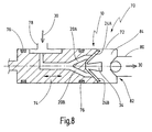
- a piston pump 70 is shown.
- the fluid pump 70 has a pump housing 72 in the form of a cylinder, in which a piston 74 is guided.
- the piston 74 is sealed relative to the cylinder housing 72 by seals 76 and / or a bellows.
- a suction port 78 is provided on an outer periphery of the pump housing 72.
- a pressure port 80 is formed at one axial end of the pump housing 72.
- a check valve 10 which is arranged at the front end of the piston 74.
- the check valve 10 corresponds in terms of construction and functioning generally the check valve of 4 to 5 or another check valve according to the embodiments described above and has two locking tabs 24 A, 24 B, between which a stop element 34 is arranged.
- the fluid pump 70 includes a second check valve 82, which is schematically indicated as a ball check valve, but may also be designed as a check valve according to one of the above embodiments. Between the check valves 10, 82, a valve space 84 is formed.
- the operation of the fluid pump 70 includes a first stroke in which the piston is moved back (in the Fig. 8 to the left), wherein via the suction port 78, a fluid is sucked into the valve space 84.
- the check valve 10 is opened and the second check valve 82 is closed.
- the piston 74 is moved in the opposite direction.
- the check valve 10 is closed and the second check valve 82 is opened, so that the fluid located in the valve chamber 84 is pushed out via the pressure port 80 until the piston 74 reaches a top dead center.
- the valve space 84 is then a dead space whose volume should be as minimal as possible.
- the stopper member 34 is formed as a volume element occupying at least 50% of the space between the locking tabs 24A, 24B. For clarity, this is in Fig. 8 not particularly illustrated.
- the extent of the deflection of the locking tabs 24A, 24B can be reduced by the stop element.
- a very high clock frequency or operating frequency of the piston 74 can be achieved.
- the fluid pump 70 since the fluid pump 70 has no or only very small dead spaces, the fluid pump is particularly suitable for conveying fluids containing crystallizable components, such as a urea solution. Such fluid pumps can thus be used in DNOX systems.
Landscapes
- Engineering & Computer Science (AREA)
- General Engineering & Computer Science (AREA)
- Mechanical Engineering (AREA)
- Check Valves (AREA)
- Details Of Reciprocating Pumps (AREA)
Description
Die vorliegende Erfindung betrifft ein Rückschlagventil mit einem Ventilgehäuse, an dem ein Ventilsitz ausgebildet ist, der in Bezug auf eine Strömungsrichtung als Schrägfläche ausgebildet ist, und mit einem Sperrelement, das wenigstens einen flächigen Sperrlappen aus einem elastisch verformbaren Material aufweist, der in einer Sperrposition an dem Ventilsitz anliegt und in einer Öffnungsposition von dem Ventilsitz abgehoben ist, um den Durchgang von Fluid zu ermöglichen, wobei auf der dem Ventilsitz abgewandten Seite des Sperrlappens ein Anschlagelement angeordnet ist, gegen das der Sperrlappen anschlagen kann, um das Maß des Abhebens des Sperrlappens von dem Ventilsitz zu begrenzen, wobei das Sperrelement zwei Sperrlappen aufweist, die im Längsschnitt V-förmig ausgerichtet sind.The present invention relates to a check valve with a valve housing, on which a valve seat is formed, which is formed with respect to a flow direction as an inclined surface, and with a locking element, which has at least one planar locking tab of an elastically deformable material in a locked position abuts the valve seat and is lifted in an open position from the valve seat to allow the passage of fluid, wherein on the valve seat side facing away from the locking tab a stop element is arranged against which the locking tab can strike to the extent of lifting the locking tab of to limit the valve seat, wherein the blocking element has two locking tabs, which are aligned in a longitudinal section V-shaped.
Die vorliegende Erfindung betrifft ferner eine Fluidpumpe mit einem Pumpengehäuse und einem darin verschieblich gelagerten Kolben, der mit dem Pumpengehäuse einen Druckraum bildet, wobei ein Sauganschluss der Pumpe über ein erstes Rückschlagventil mit dem Druckraum verbunden ist und wobei der Druckraum über ein zweites Rückschlagventil mit einem Druckanschluss der Pumpe verbunden ist.The present invention further relates to a fluid pump with a pump housing and a displaceably mounted therein piston, which forms a pressure chamber with the pump housing, wherein a suction port of the pump via a first check valve is connected to the pressure chamber and wherein the pressure chamber is connected via a second check valve to a pressure port of the pump.
Ein derartiges Rückschlagventil ist allgemein bekannt. Ein Rückschlagventil dient generell zur Richtungsbestimmung der Strömung eines Fluides und ist ein Wegeventil, das den Durchgang des Fluides in einer der zwei Strömungsrichtungen selbsttätig sperrt.Such a check valve is well known. A check valve is generally used to determine the direction of the flow of a fluid and is a directional control valve, which automatically blocks the passage of the fluid in one of the two flow directions.
Bekannt sind insbesondere sogenannte Kugelrückschlagventile, bei denen das Sperrelement durch eine Kugel gebildet ist, die durch eine Feder in den Ventilsitz gedrückt wird.In particular, so-called ball check valves are known in which the blocking element is formed by a ball which is pressed by a spring in the valve seat.
In einer alternativen Ausführungsform ist der Ventilsitz senkrecht zur Strömungsrichtung angeordnet und durch eine Klappe verschlossen. Die Klappe kann dabei insbesondere an einem oberen Bereich aufgehängt werden, so dass sie aufgrund ihres Eigengewichtes selbsttätig in die Sperrstellung gelangt.In an alternative embodiment, the valve seat is arranged perpendicular to the flow direction and closed by a flap. The flap can be hung in particular at an upper area, so that it automatically enters the blocking position due to its own weight.
Problematisch bei derartigen Rückschlagventilen ist zum einen die große Anzahl von Bauteilen. Zum anderen wird, insbesondere bei dem Rückschlagventil mit Klappe, die Fluidströmung in der Öffnungsposition aufgrund der zunächst etwa senkrecht zur Strömungsrichtung ausgerichteten Klappe gestört. Dies führt zu einem relativ geringen Wirkungsgrad. Ferner sind die erzielbaren Frequenzen bei schnellem Wechsel von Sperrposition in Öffnungsposition und umgekehrt relativ niedrig.The problem with such check valves, on the one hand, the large number of components. On the other hand, in particular in the case of the non-return valve with flap, the fluid flow in the opening position is disturbed due to the flap, which is initially aligned approximately perpendicular to the flow direction. This leads to a relatively low efficiency. Furthermore, the frequencies that can be achieved are relatively low with a rapid change from the blocking position to the opening position and vice versa.
Kolbenpumpen sind Pumpen zur Förderung von Fluiden, wobei mit dem Kolben in einem ersten Takt das zu fördernde Fluid durch ein Einlassventil angesaugt wird. Anschließend wird es in einem zweiten Takt durch das Auslassventil ausgestoßen. Eine solche Pumpe kann auch als Verdrängerpumpe bezeichnet werden.Piston pumps are pumps for conveying fluids, wherein the fluid to be delivered is sucked through an inlet valve with the piston in a first cycle. It is then expelled through the outlet valve in a second cycle. Such a pump can also be referred to as a positive displacement pump.
Aufgrund der hohen erzielbaren Drücke ist es nicht ausgeschlossen, dass zwischen dem Kolben und dem Pumpengehäuse Fluid austritt. Dies kann in geschlossenenDue to the high achievable pressures, it is not excluded that fluid escapes between the piston and the pump housing. This can be done in closed
Kreisläufen unerwünscht sein. Ferner kann dies auch unerwünscht sein, wenn das Fluid dazu neigt, bei Stillstand auszukristallisieren oder Klumpen zu bilden. Dies gilt beispielsweise bei der Verwendung der Fluidpumpe zum Pumpen von Harnstoff. Derartige Pumpen werden in Harnstoffeinspritzsystemen verwendet, wie sie in Systemen zur Abgasreinigung von Dieselmotor betriebenen Fahrzeugen verwendet werden (sogenannte DNOX-Systeme).Circuits are undesirable. Further, this may also be undesirable if the fluid tends to crystallize out at standstill or to form lumps. This applies, for example, when using the fluid pump for pumping urea. Such pumps are used in urea injection systems as used in diesel engine exhaust emission control systems (so-called DNOX systems).
Die Druckschrift
Vor dem obigen Hintergrund ist es die Aufgabe der Erfindung, ein verbessertes Rückschlagventil sowie eine verbesserte Kolbenpumpe anzugeben.Against the above background, it is the object of the invention to provide an improved check valve and an improved piston pump.
Die obige Aufgabe wird bei dem eingangs genannten Rückschlagventil dadurch gelöst, dass das Anschlagelement als sich in Strömungsrichtung konisch aufweitendes Volumenelement ausgebildet ist, das den zwischen den Sperrlappen definierten Raum zu wenigstens 50 %, insbesondere zu wenigstens 80 % ausfüllt.The above object is achieved with the check valve mentioned above in that the stop element is designed as a conically expanding volume element in the flow direction, which fills the space defined between the locking tabs to at least 50%, in particular at least 80%.
Ferner wird die obige Aufgabe bei der eingangs genannten Fluidpumpe dadurch gelöst, dass das erste und/oder das zweite Rückschlagventil als erfindungsgemäßes Rückschlagventil ausgebildet ist.Furthermore, the above object is achieved in the fluid pump mentioned above in that the first and / or the second check valve is designed as a check valve according to the invention.
Vereinfacht lässt sich die Erfindung auch formulieren als Rückschlagventil mit schrägem Ventilsitz, an dem ein Sperrlappen aus elastisch verformbarem Material anliegt, dessen Auslenkung durch ein spezielles Anschlagelement begrenzt ist.In a simplified manner, the invention can also be formulated as a non-return valve with an oblique valve seat against which a locking tab made of elastically deformable material rests whose deflection is limited by a special stop element.
Das Anschlagelement kann zwei schräge Anschlagflächen für die zwei Sperrlappen bereitstellen. Ferner wird ein in Strömungsrichtung hinter den Sperrlappen liegender Totraum reduziert. Demzufolge ergibt sich eine geringere Verlustleistung und eine verbesserte Förderleistung.The stop element can provide two inclined abutment surfaces for the two locking tabs. Furthermore, a dead space lying behind the locking tabs in the flow direction is reduced. As a result, there is less power loss and improved delivery.
Dies gilt insbesondere dann, wenn das Rückschlagventil Teil eines in Strömungsrichtung beweglichen Systems ist, beispielsweise an einem Kolben einer Fluidpumpe angeordnet ist. Hierdurch kann eine maximale Verdrängung mittels des Rückschlagventils in der Schließposition erfolgen, da der nicht genutzte Raum durch das Volumenelement ausgefüllt wird und folglich das Totvolumen im Druckbereich reduziert wird.This is especially true when the check valve is part of a movable system in the flow direction, for example, is arranged on a piston of a fluid pump. This allows a maximum displacement by means of the check valve in the closed position, since the unused space is filled by the volume element and thus the dead volume is reduced in the pressure range.
Im Bereich des Ventilsitzes ist eine Ventilöffnung ausgebildet, die eine Mehrzahl von Einzelöffnungen beinhalten kann, die gemeinschaftlich von einem Sperrlappen verschließbar sind.In the region of the valve seat, a valve opening is formed, which may include a plurality of individual openings, which are jointly closed by a locking tab.
Aufgrund der Ausbildung des Sperrlappens aus einem elastisch verformbaren Material kann erreicht werden, dass der Sperrlappen aufgrund der eigenen Elastizität in die Sperrposition vorgespannt ist. Demzufolge kann auch die Sperrposition generell sicher erreicht werden.Due to the formation of the locking tab of an elastically deformable material can be achieved that the locking tab is biased due to its own elasticity in the locked position. As a result, the lock position can also be achieved generally safely.
Vorzugsweise ist zudem der Winkel des Sperrlappens gegenüber der Längsachse im noch nicht eingebauten Zustand größer gleich und insbesondere größer als der entsprechende Winkel des Ventilsitzes. Hierdurch kann der Sperrlappen aufgrund der eigenen Elastizität sicher in die Sperrposition vorgespannt werden.Preferably, moreover, the angle of the locking tab with respect to the longitudinal axis in the not yet installed state is greater than and in particular greater than the corresponding angle of the valve seat. As a result, the locking tabs can be securely biased into the locked position due to their own elasticity.
Die Funktion des erfindungsgemäßen Rückschlagventils ähnelt der Funktion von Fischkiemen, die strömungstechnisch aufgrund der Evolution ebenfalls optimiert sind. Selbst bei vergleichweise hohen Betätigungsfrequenzen des Rückschlagventils ergibt sich hier keine Flatterneigung.The function of the check valve according to the invention is similar to the function of fish gills, which are also aerodynamically optimized due to evolution. Even with comparatively high operating frequencies of the check valve there is no flutter.
Die erzielbare hohe Dynamik wird ferner dadurch erreicht, dass das Maß des Abhebens bzw. der Auslenkung des Sperrlappens von dem Ventilsitz durch das Anschlagelement begrenzt ist. Mit anderen Worten kann der Öffnungswinkel des Sperrlappens begrenzt werden. Hierdurch kann die Betätigungsfrequenz gesteigert werden, da der Sperrlappen schneller wieder in die Sperrposition gelangen kann. Da eine Ventilöffnung in der Regel ohnehin deutlich kleiner ist als die Fläche des Sperrlappens, kann dies auch ohne Verluste der Förderrate erreicht werden.The achievable high dynamics is further achieved in that the degree of lifting or the deflection of the locking tab is limited by the valve seat by the stop element. In other words, the opening angle of the locking tab can be limited. As a result, the actuation frequency can be increased because the locking tab can get back into the locked position faster. Since a valve opening is usually much smaller than the area of the locking tab, this can be achieved even without loss of the delivery rate.
Das erfindungsgemäße Rückschlagventil ist für vergleichsweise hohe Betätigungsfrequenzen geeignet, beispielsweise für Betätigungsfrequenzen bis zu 20 Hz oder sogar bis zu 60 oder 70 Hz oder noch höher.The check valve according to the invention is suitable for comparatively high actuation frequencies, for example for actuation frequencies of up to 20 Hz or even up to 60 or 70 Hz or even higher.
Zudem kann sich eine höhere Lebensdauer ergeben, da der elastisch verformbare Sperrlappen nur begrenzt ausgelenkt wird. Auch kann hierdurch gegebenenfalls eine geringere Verlustleistung erreicht werden, da das Schließen des Rückschlagventils schneller erfolgen kann und weniger Fluid hierbei zurückströmt.In addition, a longer service life may result, since the elastically deformable locking tab is deflected only limited. Also, this may optionally lower power dissipation be achieved because the closing of the check valve can be done faster and less fluid flows back here.
Bei der erfindungsgemäßen Fluidpumpe kann ebenfalls eine höhere Dynamik bzw. eine höhere Pumpfrequenz des Kolbens erreicht werden.In the fluid pump according to the invention, a higher dynamics or a higher pump frequency of the piston can likewise be achieved.
Die Aufgabe wird somit vollkommen gelöst.The task is thus completely solved.
Bei dem erfindungsgemäßen Rückschlagventil ist es von besonderem Vorteil, wenn eine Anschlagfläche des Anschlagelementes schräg ausgerichtet ist, derart, dass der Sperrlappen auch in der Öffnungsposition schräg ausgerichtet ist.In the check valve according to the invention, it is particularly advantageous if a stop surface of the stop element is aligned obliquely, such that the locking tab is also aligned obliquely in the open position.
Generell ist es möglich, dass der Sperrlappen in der Öffnungsposition flächig an der Anschlagfläche anliegt. Besonders bevorzugt ist jedoch, wenn der Sperrlappen in der Öffnungsposition einen anderen Winkel aufweist als die entsprechende Anschlagfläche. Hierdurch kann ein Anhaften der Flächen aufgrund adhäsiver Kräfte vermieden werden.In general, it is possible that the locking tab in the open position lies flat against the stop surface. However, it is particularly preferred if the locking tab in the opening position has a different angle than the corresponding stop surface. As a result, adhesion of the surfaces due to adhesive forces can be avoided.
Im Idealfall kann der Sperrlappen in der Öffnungsposition flächig an der Anschlagfläche anliegen. Hierdurch können punktuelle Druckbelastungen auf die dem Anschlagelement zugewandte Seite des Sperrlappens vermieden werden.Ideally, in the opening position, the locking tab can lie flat against the stop surface. In this way, selective pressure loads on the stop element facing the side of the locking tab can be avoided.
Gemäß einer weiteren bevorzugten Ausführungsform erstreckt sich das Anschlagelement in Strömungsrichtung etwa so weit wie der Sperrlappen.According to a further preferred embodiment, the stop element extends in the flow direction approximately as far as the locking tab.
Hierdurch kann zum einen erreicht werden, dass auch ein in Strömungsrichtung distales Ende des Sperrlappens an dem Anschlagelement anliegt. Hierdurch kann vermieden werden, dass sich das distale Ende gegenüber dem Anschlagelement abbiegt. Ferner kann hierdurch auch die erzielbare Dynamik nochmals gesteigert werden.In this way, on the one hand, it can be achieved that a distal end of the blocking tab in the direction of flow also bears against the stop element. In this way it can be avoided that the distal end bends against the stop element. Furthermore, this also the achievable dynamics can be increased again.
Generell kann das Anschlagelement Teil des Ventilgehäuses sein oder als separates Bauteil an dem Ventilgehäuse befestigt sein.In general, the stop element may be part of the valve housing or attached to the valve housing as a separate component.
Besonders bevorzugt ist es jedoch, wenn das Anschlagelement einstückig mit dem Sperrelement ausgebildet ist.However, it is particularly preferred if the stop element is formed integrally with the blocking element.
Bei dieser Ausführungsform kann die Bauteilanzahl bzw. die Komplexität des Ventilgehäuses verringert werden.In this embodiment, the number of components or the complexity of the valve housing can be reduced.
Dabei ist es besonders bevorzugt, wenn im Bereich des Übergangs zwischen dem Anschlagelement und dem Sperrlappen eine Ausnehmung ausgebildet ist, die zur Erhöhung der Beweglichkeit des Sperrlappens dient.It is particularly preferred if a recess is formed in the region of the transition between the stop element and the locking tab, which serves to increase the mobility of the locking tab.
Bei dieser Ausführungsform kann der Sperrlappen eine gewisse Dicke besitzen, die auch bei einer großen Ventilöffnung in dem Ventilsitz für eine stabile Lage des Sperrlappens in der Sperrposition sorgen kann. Zum anderen kann durch eine solche Ausnehmung, die am proximalen Ende des Sperrlappens ausgebildet ist, die Beweglichkeit in Öffnungsrichtung bzw. Schließrichtung erhöht werden. Durch die somit erzielte Verbesserung der Biegeflexiblität gegenüber der Dicke des Sperrlappens im Dichtbereich kann folglich die Dynamik des Rückschlagventils noch einmal verbessert werden.In this embodiment, the locking tab may have a certain thickness, which can provide a stable position of the locking tab in the locked position, even with a large valve opening in the valve seat. On the other hand, the mobility in the opening direction or closing direction can be increased by such a recess, which is formed at the proximal end of the locking tab. As a result of the thus achieved improvement in bending flexibility compared to the thickness of the locking tab in the sealing region, the dynamics of the check valve can consequently be improved once more.
Bei dieser Ausführungsform sind an dem Ventilgehäuse in der Regel auch zwei Ventilsitze ausgebildet, die in entsprechender Weise im Längsschnitt eine V-Form bilden.In this embodiment, two valve seats are also formed on the valve housing in the rule, which form in a corresponding manner in longitudinal section a V-shape.
Hierdurch kann bei relativ geringem Bauraum eine hohe Durchflussmenge erreicht werden. Das Ventil beinhaltet folglich zwei parallele Rückschlagventile. Auf diese Weise können auch die auftretenden Radialkräfte gegeneinander kompensiert werden. Daher eignet sich diese Ausbildung bevorzugt auch dann, wenn das Rückschlagventil Teil eines in Strömungsrichtung beweglichen Systems ist, beispielsweise an einem Kolben einer Fluidpumpe angeordnet ist.As a result, a high flow rate can be achieved with a relatively small space. The valve thus includes two parallel check valves. In this way, the radial forces occurring can be compensated against each other. Therefore, this training is preferably also when the check valve is part of a movable system in the flow direction, for example, is arranged on a piston of a fluid pump.
Dabei ist es von besonderem Vorteil, wenn die zwei Sperrlappen einstückig miteinander verbunden sind. Hierdurch kann die Bauteilanzahl gering gehalten werden. Bei der erfindungsgemässen Ausführungsform ist das Anschlagelement im Bereich zwischen den Sperrlappen angeordnet.It is particularly advantageous if the two locking tabs are integrally connected. As a result, the number of components can be kept low. In the embodiment according to the invention, the stop element is arranged in the region between the locking tabs.
Hierdurch kann das Anschlagelement sowohl eine Anschlagfläche für den einen Sperrlappen als auch eine Anschlagfläche für den zweiten Sperrlappen aufweisen. Gemäß einer weiteren bevorzugten Ausführungsform ist das Anschlagelement so angeordnet, dass die Sperrlappen sich nicht berühren können.In this way, the stop element may have both a stop surface for the one locking tab and a stop surface for the second locking tab. According to a further preferred embodiment, the stop element is arranged so that the locking tabs can not touch.
Hierdurch können auch wechselseitige Beeinflussungen der Sperrlappen verhindert werden.As a result, mutual interference of the locking tabs can be prevented.
Insgesamt ist es ferner vorteilhaft, wenn das Sperrelement einen Befestigungsabschnitt aufweist, mittels dessen das Sperrelement an dem Ventilgehäuse befestigt ist.Overall, it is also advantageous if the blocking element has a fastening portion, by means of which the blocking element is attached to the valve housing.
Die Befestigung kann dabei mittels Schrauben erfolgen, durch Kleben, durch geometrischen Formschluss oder andere Befestigungsarten.The attachment can be done by means of screws, by gluing, by geometric form-fitting or other types of fastening.
Besonders bevorzugt ist es jedoch, wenn das Ventilgehäuse eine Befestigungsausnehmung aufweist, die quer zur Strömungsrichtung ausgerichtet ist, wobei der Befestigungsabschnitt in die Befestigungsausnehmung eingesetzt ist, um das Sperrelement in Strömungsrichtung formschlüssig an dem Ventilgehäuse festzulegen.However, it is particularly preferred if the valve housing has a mounting recess, which is aligned transversely to the flow direction, wherein the mounting portion is inserted into the mounting recess to fix the locking element in the flow direction form-fitting manner to the valve housing.
Auf diese Weise kann die Befestigung des Sperrelementes an dem Ventilgehäuse ohne weitere Bauteile oder Materialien erfolgen. Denkbar hierbei ist, dass das Sperrelement einen quer zur Strömungsrichtung verlaufenden Wulst aufweist, der in eine entsprechende, quer verlaufende Ausnehmung des Ventilgehäuses eingesetzt ist, um eine axial formschlüssige Verbindung zu erzielen.In this way, the attachment of the blocking element to the valve housing without additional components or materials can be done. It is conceivable here that the blocking element has a bead extending transversely to the flow direction, which is inserted into a corresponding, transversely extending recess of the valve housing in order to achieve an axially positive connection.
Von besonderem Vorteil ist es jedoch, wenn der Befestigungsabschnitt einen Ringabschnitt aufweist, der in eine ringförmige Befestigungsausnehmung des Ventilgehäuses eingesetzt ist.It is particularly advantageous, however, if the attachment portion has a ring portion which is inserted into an annular mounting recess of the valve housing.
Hierbei ist von besonderem Vorteil, dass das Sperrelement ohne weitere Maßnahmen auch in radialer Richtung an dem Ventilgehäuse fixiert werden kann.It is of particular advantage that the blocking element can be fixed without further measures in the radial direction of the valve housing.
Ferner ist es hierbei vorteilhaft, wenn der Ringabschnitt über wenigstens einen Längsstegabschnitt mit dem Sperrlappen verbunden ist.Furthermore, it is advantageous in this case if the ring section is connected to the locking tab via at least one longitudinal web section.
Dies ermöglicht eine einstückige Ausbildung des Sperrelementes, wobei der Längsstegabschnitt den Ringabschnitt und den Sperrlappen (oder die zwei Sperrlappen) miteinander verbindet.This allows a one-piece design of the locking element, wherein the longitudinal web portion connects the ring portion and the locking tab (or the two locking tabs) together.
Ferner ist es vorteilhaft, wenn der Längsstegabschnitt in einer längs ausgerichteten Ausnehmung des Ventilgehäuses angeordnet ist.Furthermore, it is advantageous if the longitudinal web section is arranged in a longitudinally aligned recess of the valve housing.
Hierdurch kann der Befestigungsabschnitt des Sperrelementes beispielsweise in eine Zylinderkontur des Ventilgehäuses integriert werden, ohne dass der Befestigungsabschnitt in radialer Richtung nach außen gegenüber der Zylinderkontur vorsteht. Insbesondere ist diese Ausbildung daher für die Verwendung des Rückschlagventils an einem beweglichen Element wie einen Kolben geeignet.In this way, the attachment portion of the locking element can be integrated, for example, in a cylinder contour of the valve housing, without the attachment portion projecting in the radial direction outwards relative to the cylinder contour. In particular, this embodiment is therefore suitable for the use of the check valve on a movable element such as a piston.
Ferner ist es hierbei vorteilhaft, wenn die zwei Sperrlappen an einem Quersteg miteinander verbunden sind (beispielsweise in V-Form), dessen Enden jeweils über einen Längsstegabschnitt mit dem Ringabschnitt verbunden sind.Further, it is advantageous in this case if the two locking tabs are connected to one another at a transverse web (for example in V-shape), the ends of which are each connected to the annular section via a longitudinal web section.
Diese Ausführungsform ermöglicht eine in axialer Richtung stabile Verbindung zwischen den Sperrlappen und dem Ringabschnitt.This embodiment enables an axially stable connection between the locking tab and the ring portion.
Insgesamt ist es ferner bevorzugt, wenn das Ventilgehäuse einen Zylinderabschnitt aufweist, der wenigstens einen mit der Ventilöffnung verbundenen Längskanal aufweist, wobei der Ventilsitz an einer Stirnseite des Zylinderabschnittes ausgebildet ist.Overall, it is further preferred if the valve housing has a cylinder portion which has at least one longitudinal passage connected to the valve opening, wherein the valve seat is formed on an end face of the cylinder portion.
Diese Ausführungsform ermöglicht zum einen einen einfachen Gehäuseaufbau. Denn der zweite Druckraum kann hierbei beispielsweise durch den Zylinderabschnitt und einen zweiten Gehäuseabschnitt gebildet sein. Der Längskanal bildet vorzugsweise einen Teil eines ersten Druckraumes. Ferner ist hierbei vorteilhaft, dass sich das Rückschlagventil auf einfache Weise in einen zylinderförmigen Kolben integrieren lässt, und zwar an dessen Stirnseite.This embodiment allows for a simple housing structure. For the second pressure chamber can be formed for example by the cylinder portion and a second housing portion. The longitudinal channel preferably forms part of a first pressure chamber. Furthermore, it is advantageous in this case that the check valve can be integrated in a simple manner into a cylindrical piston, specifically on its end face.
Ausführungsbeispiele der Erfindung sind in der Zeichnung dargestellt und werden in der nachfolgenden Beschreibung näher erläutert. Es zeigen:
- Fig. 1
- eine schematische Längsschnittansicht durch ein Rückschlagventil in einer Sperrposition;
- Fig. 2
- das Rückschlagventil der
Fig. 1 in einer Öffnungsposition; - Fig. 3
- eine erste Ausführungsform eines erfindungsgemäßen Rückschlagventiles im schematischen Längsschnitt;
- Fig. 4
- eine Seitenansicht einer weiteren Ausführungsform eines erfindungsgemäβen Rückschlagventils;
- Fig. 5
- eine Längsschnittansicht durch das Rückschlagventil der
Fig. 4 ; - Fig. 6
- ein Sperrelement eines erfindungsgemäßen Rückschlagventils, das sich insbesondere in Verbindung mit dem Rückschlagventil der
Fig. 4 und5 verwenden lässt; und - Fig. 7
- eine abgewandelte Ausführungsform eines Ventilgehäuses des Rückschlagventils der
Fig. 4 und5 ; und - Fig. 8
- eine schematische Darstellung einer erfindungsgemäßen Fluidpumpe.
- Fig. 1
- a schematic longitudinal sectional view through a check valve in a locking position;
- Fig. 2
- the check valve the
Fig. 1 in an open position; - Fig. 3
- a first embodiment of a check valve according to the invention in a schematic longitudinal section;
- Fig. 4
- a side view of another embodiment of a erfindungsgemäβen check valve;
- Fig. 5
- a longitudinal sectional view through the check valve of
Fig. 4 ; - Fig. 6
- a blocking element of a check valve according to the invention, which in particular in connection with the check valve of
Fig. 4 and5 to use; and - Fig. 7
- a modified embodiment of a valve housing of the check valve of
Fig. 4 and5 ; and - Fig. 8
- a schematic representation of a fluid pump according to the invention.
In
Im Inneren des Ventilgehäuses 12 ist ein Ventilraum ausgebildet, der mit dem zweiten Druckraum 16 verbunden ist.Inside the
Das Rückschlagventil richtet eine Strömungsrichtung S ein, über die Fluid von dem ersten Druckraum 14 in den zweiten Druckraum 16 gelangen kann. Die Strömungsrichtung S ist parallel zu einer Längserstreckung des Rückschlagventils 10.The check valve establishes a flow direction S, via which fluid can pass from the
Eine dem ersten Druckraum 14 zugewandte Seite des Ventilraumes ist als Ventilsitz 18 ausgebildet. Der Ventilsitz 18 ist dabei als Schrägfläche ausgebildet, die in Bezug auf die Strömungsrichtung S einen Winkel größer 15° und kleiner 80° einnimmt, insbesondere größer 30° und kleiner 60°, im vorliegenden Fall 45°.A side of the valve chamber facing the
An dem Ventilsitz 18 ist eine Ventilöffnung 19 ausgebildet, die über einen Längskanal 20 in dem Ventilgehäuse 12 mit dem ersten Druckraum 14 verbunden ist. Die Ventilöffnung 19 kann eine einzelne Ventilöffnung sein oder aus einer Mehrzahl von separaten Einzelöffnungen bestehen, die mit dem ersten Druckraum 14 verbunden sind.At the
Die Schrägfläche des Ventilsitzes 18 kann als plane Fläche ausgebildet sein, wie es in
In dem Ventilraum ist ferner ein Sperrelement 22 des Rückschlagventils 10 angeordnet. Das Sperrelement 22 ist aus einem elastisch verformbaren Material, insbesondere einem Kunststoffmaterial hergestellt und weist einen Sperrlappen 24 auf. Der Sperrlappen 24 ist hinsichtlich seiner Form an den Ventilsitz 18 angepasst, ist also im vorliegenden Fall als ebener Lappen ausgebildet (kann jedoch ein gewölbter Lappen sein).In the valve chamber, a blocking
Das Sperrelement 22 weist ferner einen einstückig mit dem Sperrlappen 24 ausgebildeten Befestigungsabschnitt 26 auf. Der Befestigungsabschnitt 26 ist in einem in Strömungsrichtung S gesehen hinteren Bereich des Ventilsitzes 18 an dem Ventilgehäuse 12 festgelegt. Hierzu verwendete Befestigungsmittel 28 sind in
Das Sperrelement 22 ist wie gesagt aus einem elastischen Material gebildet und ist über den Befestigungsabschnitt 26 so an dem Ventilgehäuse 12 angebracht, dass ein Sperrlappen 24 in einer entspannten Position (also nicht elastisch ausgelenkt) an dem Ventilsitz 18 anliegt. Alternativ ist es auch möglich, das Sperrelement so auszubilden, dass der Sperrlappen 24 mit einer gewissen Vorspannung in Richtung entgegengesetzt zu der Strömungsrichtung S an dem Ventilsitz 18 anliegt.The blocking
In
Es versteht sich, dass bei der obigen Betrachtung der Drücke auch der von dem Sperrelement 22 gegebenenfalls aufgebrachte Eigendruck entgegen der Strömungsrichtung S mit berücksichtigt sein kann.It is understood that in the above consideration of the pressures and the optionally applied by the blocking
In
Insgesamt kann mit dem Rückschlagventil eine hohe Betätigungsfrequenz erreicht werden, beispielsweise größer 50 Hz, ohne dass ein Flattern des Sperrelementes auftritt. Die Form des Sperrlappens 24 kann ferner so gewählt sein, dass bei einer Druckumkehr zur Einleitung eines Saugtaktes ein Zurückdrücken des Sperrlappens in Richtung gegen den Ventilsitz 18 begünstigt wird (beispielsweise durch geeignete Ausformung eines vorderen Endes des Sperrlappens, wie es in
In
Das Anschlagelement weist eine Anschlagfläche 35 auf, die vorzugsweise schräg ausgerichtet ist, und zwar so, dass die dem Ventilsitz 18 abgewandte Seite des Sperrlappens 24 in der Öffnungsposition flächig daran anliegt.The stop element has a
Die Betätigungsfrequenz des Rückschlagventils kann durch das Anschlagelement 34 weiter erhöht werden. Denn durch das Anschlagelement kann verhindert werden, dass das Anschlagelement bis parallel zur Strömungsrichtung oder darüber hinaus ausgelenkt wird. Demzufolge kann das Sperrelement auch schneller wieder von der Öffnungsposition in die Sperrposition zurückbewegt werden.The actuation frequency of the check valve can be further increased by the
Nachstehend werden weitere alternative Ausführungsformen von erfindungsgemäβen Rückschlagventilen erläutert. Diese entsprechen hinsichtlich dem generellen Aufbau und der generellen Funktionsweise dem oben beschriebenen Rückschlagventil 10 der
Ferner weist das Rückschlagventil 10 der
Jedem der Ventilsitze 18A, 18B ist ein eigener Längskanal 20 zugeordnet, wobei die Längskanäle 20 jeweils mit dem ersten Druckraum 14 verbunden sind. In
Ferner sind die zwei Sperrlappen 24A, 24B einstückig miteinander verbunden, zwar über einen Quersteg 48. In der dargestellten Ausführungsform ist der Quersteg 48 im Längsschnitt wulstförmig ausgebildet und ist in Querrichtung (senkrecht zur Darstellungsebene) in eine Befestigungsausnehmung 50 des ersten Teilgehäuses 40 eingeschoben. Hierdurch kann das Sperrelement 22 ohne weitere Befestigungsmittel in Strömungsrichtung S formschlüssig mit dem ersten Teilgehäuse 40 verbunden werden.In the illustrated embodiment, the
Der mit dem zweiten Druckraum 16 verbundene Ventilraum ist in dieser Ausführungsform zwischen dem ersten und dem zweiten Teilgehäuses 40, 42 ausgebildet. Das zweite Ventilgehäuse 42 kann dabei eine Konusfläche 52 beinhalten, die sich in Strömungsrichtung verjüngt, hin zu dem zweiten Druckraum 16. Hierdurch kann die Strömung des Fluides 30 in der Öffnungsposition hinsichtlich strömungstechnischer Gesichtpunkte noch weiter optimiert werden.The valve chamber connected to the
In
Es ist zu erkennen, dass in
Die Längsstegabschnitte 58 sind an ihrem dem Ringabschnitt 56 abgewandten Ende mit einem jeweiligen radialen Ende eines Quersteges 48 verbunden, der die Sperrlappen 24A, 24B miteinander verbindet. Das eine Ende des Quersteges 48 ist in
Bei 63 sind ferner in
Das Anschlagelement 34 ist bei dieser Ausführungsform einstückig mit dem Sperrelement 22 ausgebildet und erstreckt sich konisch aufweitend zwischen den zwei Sperrlappen 24A, 24B. Der maximale Öffnungswinkel der Sperrlappen 24A, 24B, bei denen diese an den jeweiligen Anschlagflächen 35A, 35B anliegen, beträgt im vorliegenden Fall etwa 10°.The
Das Anschlagelement 34 erstreckt sich in Strömungsrichtung S etwa bis zum Ende der Sperrlappen 24A, 24B, so dass der dazwischen definierte Raum zu mindestens 50 %, im vorliegenden Fall zu etwa 80 % ausgefüllt ist. Hierdurch wird ein Totvolumen verringert, das sich in Strömungsrichtung an das Sperrelement anschließt.The
Das Anschlagelement 34 ist ferner so ausgebildet, dass die Sperrlappen 24A, 24B sich nicht berühren können.The
Im Bereich eines Überganges zwischen dem Anschlagelement 34 und den Sperrlappen 24A, 24B ist jeweils eine im Wesentlichen quer zur Längsachse 60 ausgerichtete Ausnehmung 66A bzw. 66B ausgebildet. Die Ausnehmungen 66A, 66B dienen der Erhöhung der Beweglichkeit bzw. Biegeflexibilität der Sperrlappen 24A, 24B. Die Ausnehmungen 66A, 66B sind vorzugsweise in axialer Projektion nicht überschneidend sondern benachbart zu den Längskanälen 20A, 20B angeordnet, die jeweils in den Ventilsitzen 18A, 18B in Form jeweiliger Ventilöffnungen 19A, 19B münden.In the region of a transition between the
In
Die oben beschriebenen Ausführungsformen von Rückschlagventilen lassen sich sämtlich als stationäre, unbewegliche Rückschlagventile in einer beliebigen Anwendung verwenden. Als Fluid kommen sowohl flüssige als auch gasförmige Stoffe in Betracht.The embodiments of check valves described above can all be used as stationary, fixed check valves in any application. As fluid both liquid and gaseous substances are considered.
In
Ferner beinhaltet die Fluidpumpe 70 ein zweites Rückschlagventil 82, das schematisch als Kugelrückschlagventil angedeutet ist, jedoch ebenfalls als Rückschlagventil gemäß einer der obigen Ausführungsformen ausgebildet sein kann. Zwischen den Rückschlagventilen 10, 82 ist ein Ventilraum 84 ausgebildet.Furthermore, the
Die Funktionsweise der Fluidpumpe 70 beinhaltet einen ersten Arbeitstakt, bei dem der Kolben zurückbewegt wird (in der
Im Anschluss an den zweiten Arbeitstakt schließt sich wieder ein dritter Arbeitstakt an, der dem ersten Arbeitstakt entspricht.Following the second work cycle, a third work cycle follows, which corresponds to the first work cycle.
Durch das Anschlagelement kann zudem das Maß der Auslenkung der Sperrlappen 24A, 24B verringert werden. Hierdurch kann eine sehr hohe Taktfrequenz bzw. Betätigungsfrequenz des Kolbens 74 erreicht werden. Demzufolge ergibt sich eine hohe Förderleistung. Aufgrund des geringen Totvolumens ergibt sich zudem eine geringe Verlustleistung.In addition, the extent of the deflection of the
Da die Fluidpumpe 70 zudem keine oder nur sehr geringe Toträume aufweist, eignet sich die Fluidpumpe insbesondere zum Fördern von Fluiden, die auskristallisierbare Bestandteile beinhalten, wie beispielsweise eine Harnstofflösung. Derartige Fluidpumpen können folglich in DNOX-Systemen verwendet werden.In addition, since the
Claims (7)
- A check valve (10) with a valve housing (12), on which is formed a valve seat (18) which is designed as an oblique face with respect to a flow direction (S), and with a shut-off element (22) having at least one sheet-like shut-off tab (24) which is composed of an elastically deformable material and which, in a shut-off position, bears against the valve seat (18) and, in an opening position, is lifted off from the valve seat (18), in order to allow the passage of fluid (30), there being arranged on that side of the shut-off tab (24) which faces away from the valve seat an abutment element (34), against which the shut-off tab (24) can abut, in order to limit the amount by which the shut-off tab (24) is lifted off from the valve seat, wherein the shut-off element (22) has two shut-off tabs (24A, 24B) which are oriented in a V-shaped manner in longitudinal section,
characterized in that
the abutment element (34) is designed as volume element which widens conically in the flow direction (S) and which fills the space defined between the shut-off tabs (24A, 24B) in an amount of at least 50%. - The check valve as claimed in claim 1, an abutment face (35) of the abutment element (34) being oriented obliquely in such a way that the shut-off tab (24) is also oriented obliquely in the opening position.
- The check valve as claimed in claim 1 or 2, characterized in that the abutment element (34) extends approximately as far as the shut-off tab (24) in the flow direction (S).
- The check valve as claimed in one of claims 1 - 3, characterized in that the abutment element (34) is formed in one piece with the shut-off element (22).
- The check valve as claimed in claim 4, characterized in that a recess (66), which serves for increasing the movability of the shut-off tab (24), is formed in the region of the transition between the abutment element (34) and the shut-off tab (24).
- The check valve as claimed in one of claims 1- 5, characterized in that the abutment element (34) is arranged such that the shut-off tabs (24A, 24B) cannot touch each other.
- A fluid pump (70) with a pump housing (72) and with a piston which is mounted displaceably therein and forms with the pump housing (72) a pressure space, a suction connection of the pump (70) being connected to the pressure space via a first check valve, and the pressure space being connected to a pressure connection of the pump via a second check valve, characterized in that the first and/or the second check valve are/is designed according to one of claims 1 - 6.
Applications Claiming Priority (2)
| Application Number | Priority Date | Filing Date | Title |
|---|---|---|---|
| DE200910018930 DE102009018930B4 (en) | 2009-04-28 | 2009-04-28 | check valve |
| PCT/EP2010/002365 WO2010124798A1 (en) | 2009-04-28 | 2010-04-17 | Check valve |
Publications (2)
| Publication Number | Publication Date |
|---|---|
| EP2425162A1 EP2425162A1 (en) | 2012-03-07 |
| EP2425162B1 true EP2425162B1 (en) | 2014-07-23 |
Family
ID=42226435
Family Applications (1)
| Application Number | Title | Priority Date | Filing Date |
|---|---|---|---|
| EP20100718469 Active EP2425162B1 (en) | 2009-04-28 | 2010-04-17 | Check valve |
Country Status (6)
| Country | Link |
|---|---|
| US (1) | US8608464B2 (en) |
| EP (1) | EP2425162B1 (en) |
| JP (1) | JP5615905B2 (en) |
| CN (1) | CN102439338B (en) |
| DE (1) | DE102009018930B4 (en) |
| WO (1) | WO2010124798A1 (en) |
Families Citing this family (15)
| Publication number | Priority date | Publication date | Assignee | Title |
|---|---|---|---|---|
| US8998838B2 (en) * | 2012-03-29 | 2015-04-07 | Alcon Research, Ltd. | Adjustable valve for IOP control with reed valve |
| FR2991423B1 (en) * | 2012-05-30 | 2015-05-01 | Coutier Moulage Gen Ind | NON-RETURN VALVE OF THE MEMBRANE TYPE |
| CN104033632A (en) * | 2013-03-07 | 2014-09-10 | 北京华德创业环保设备有限公司 | Flexible valve clack check valve |
| US9086160B2 (en) * | 2013-03-18 | 2015-07-21 | William Anthony Harper | Biflex film valves |
| US9226851B2 (en) | 2013-08-24 | 2016-01-05 | Novartis Ag | MEMS check valve chip and methods |
| CN103591343B (en) * | 2013-11-15 | 2015-12-30 | 海信(山东)冰箱有限公司 | One-way valve, many warm areas air flue structure and chiller plant |
| KR101608589B1 (en) | 2014-08-18 | 2016-04-01 | 지엠 글로벌 테크놀러지 오퍼레이션스 엘엘씨 | Check valve for ureawater injection and ureawater supply apparatus having the same |
| CN105090655B (en) * | 2015-07-22 | 2018-03-06 | 大禹节水(天津)有限公司 | Drip irrigation below the surface special single-way pipe connects bypass and preparation method |
| CN106168207A (en) * | 2016-06-14 | 2016-11-30 | 宁波新邦工具有限公司 | A kind of rotary extrusion type compressed air generating means |
| CN106907508B (en) * | 2017-04-19 | 2022-12-13 | 宁波合力机泵股份有限公司 | Multi-runner outlet one-way valve for gas, liquid or gas-liquid mixed multi-medium compression pump |
| CN108150316B (en) * | 2017-12-25 | 2021-01-19 | 潍柴动力股份有限公司 | EGR mixing device and internal combustion engine |
| DE102018009963A1 (en) | 2018-12-21 | 2020-06-25 | Aventics Gmbh | Sealing membrane and check valve with sealing membrane for fluid power applications |
| DE102020108055A1 (en) * | 2020-03-24 | 2021-09-30 | Mann+Hummel Gmbh | Particle discharge device, filter assembly and method |
| JP7523935B2 (en) * | 2020-04-06 | 2024-07-29 | 株式会社ミクニ | Reed valve |
| US11268627B1 (en) | 2020-09-08 | 2022-03-08 | Magic Plastics, Inc. | Adjustable check valve |
Family Cites Families (32)
| Publication number | Priority date | Publication date | Assignee | Title |
|---|---|---|---|---|
| US1408724A (en) * | 1920-08-13 | 1922-03-07 | Worthington Pump & Mach Corp | Pump or compressor valve |
| US3208472A (en) * | 1963-07-15 | 1965-09-28 | Scaramucci Domer | Dual flapper check valve |
| US3312237A (en) * | 1964-05-06 | 1967-04-04 | Mon George | Bicuspid heart valve |
| US3473561A (en) * | 1966-03-29 | 1969-10-21 | Bert N Svenson | Check valve with supported closure member |
| US3990439A (en) * | 1974-12-05 | 1976-11-09 | Esb Incorporated | Protective breathing apparatus and valve therefor |
| US3951168A (en) * | 1974-12-27 | 1976-04-20 | Fisher Controls Company, Inc. | Curtain valve |
| JPS6039584Y2 (en) * | 1976-09-06 | 1985-11-27 | 株式会社トキメック | check valve |
| JPS5650870U (en) * | 1979-09-26 | 1981-05-06 | ||
| JPS60108859U (en) * | 1983-12-28 | 1985-07-24 | エヌオーケー株式会社 | reed valve |
| DE3414077A1 (en) * | 1984-04-13 | 1985-10-24 | Passavant-Werke AG & Co KG, 6209 Aarbergen | ANGLE-CHANGEABLE KNEE PIECE |
| JPS6154566U (en) * | 1984-09-14 | 1986-04-12 | ||
| JPH0410387Y2 (en) * | 1985-07-04 | 1992-03-13 | ||
| CH685454A5 (en) | 1992-03-11 | 1995-07-14 | Inventa Ag | Check valve. |
| JP3158733B2 (en) * | 1992-10-30 | 2001-04-23 | トヨタ自動車株式会社 | Check valve |
| US5245956A (en) * | 1993-01-11 | 1993-09-21 | Barry Davidson | Reed valve assembly |
| JP3474222B2 (en) * | 1993-06-21 | 2003-12-08 | 理想科学工業株式会社 | Apparatus for removing contents from container and container |
| US5518026A (en) * | 1994-09-30 | 1996-05-21 | G. T. Products, Inc. | Filler neck butterfly check valve |
| IL112444A (en) * | 1995-01-25 | 1998-01-04 | Raviv Precision Injection Mold | Roll over vent valve |
| US6050294A (en) * | 1999-03-17 | 2000-04-18 | Val-Matic Valve And Manufacturing Corp. | Spring return check valve |
| AT3873U1 (en) * | 1999-03-29 | 2000-09-25 | Tesma Motoren Getriebetechnik | CHECK VALVE FOR A FILLING TUBE OF A FUEL TANK OF A MOTOR VEHICLE |
| US6098656A (en) * | 1999-11-15 | 2000-08-08 | Farina; Alfred J. | Check valve |
| JP2002054443A (en) * | 2000-08-14 | 2002-02-20 | Kioritz Corp | Two-stroke internal combustion engine |
| US6648012B2 (en) * | 2001-06-13 | 2003-11-18 | Applied Materials, Inc. | Non-return valve override device |
| WO2004067965A1 (en) * | 2003-01-31 | 2004-08-12 | Shinano Kenshi Kabushiki Kaisha | Valve structure and positive displacement pump using the valve structure |
| CN2627305Y (en) * | 2003-05-18 | 2004-07-21 | 沈李相 | Non-return flap valve |
| JP4143841B2 (en) * | 2003-09-18 | 2008-09-03 | 株式会社アドヴィックス | Piston pump |
| US20060081292A1 (en) * | 2004-10-15 | 2006-04-20 | Magic Plastics, Inc. | Quickly opening hinged check valve with pre-determined upstream pressure required to open |
| US20070056648A1 (en) * | 2005-09-09 | 2007-03-15 | Eaton Corporation | Two-piece valve |
| DE202005019518U1 (en) * | 2005-12-14 | 2007-04-26 | Hengst Gmbh & Co.Kg | Device for venting the crankcase of an internal combustion engine |
| US20070157970A1 (en) * | 2006-01-11 | 2007-07-12 | Sunonwealth Electric Machine Industry Co., Ltd. | Check valve for fluid |
| US8201576B2 (en) * | 2006-04-05 | 2012-06-19 | Klein Gerald A | Reinforced elastomeric hinge check valve |
| DE102008006686B4 (en) * | 2008-01-21 | 2010-03-18 | Prettl, Rolf | check valve |
-
2009
- 2009-04-28 DE DE200910018930 patent/DE102009018930B4/en not_active Expired - Fee Related
-
2010
- 2010-04-17 EP EP20100718469 patent/EP2425162B1/en active Active
- 2010-04-17 WO PCT/EP2010/002365 patent/WO2010124798A1/en not_active Ceased
- 2010-04-17 CN CN201080019095.1A patent/CN102439338B/en not_active Expired - Fee Related
- 2010-04-17 JP JP2012507622A patent/JP5615905B2/en not_active Expired - Fee Related
-
2011
- 2011-10-18 US US13/275,834 patent/US8608464B2/en active Active
Also Published As
| Publication number | Publication date |
|---|---|
| CN102439338B (en) | 2015-08-12 |
| JP2012525548A (en) | 2012-10-22 |
| DE102009018930B4 (en) | 2013-08-08 |
| US8608464B2 (en) | 2013-12-17 |
| CN102439338A (en) | 2012-05-02 |
| EP2425162A1 (en) | 2012-03-07 |
| WO2010124798A1 (en) | 2010-11-04 |
| US20120121449A1 (en) | 2012-05-17 |
| JP5615905B2 (en) | 2014-10-29 |
| DE102009018930A1 (en) | 2010-11-18 |
Similar Documents
| Publication | Publication Date | Title |
|---|---|---|
| DE102009018930B4 (en) | check valve | |
| EP2245348B1 (en) | Check valve and piston pump having check valve | |
| EP2488776B1 (en) | Pressure retaining valve | |
| EP1671031B1 (en) | Fluid pump, particularly high-pressure fuel pump | |
| DE69326985T2 (en) | FUEL INJECTION VALVE WITH HIGH PRESSURE LIMIT VALVE | |
| EP3194757A1 (en) | Fuel injection valve for combustion engines | |
| DE4428667C2 (en) | Combined flow control and pressure control valve for one pump and with cartridge-shaped valve housing | |
| DE3248622A1 (en) | High-pressure cleaning device | |
| EP4107386A1 (en) | Fuel injection valve for internal combustion engines | |
| WO2012123131A1 (en) | Valve device, in particular outlet valve of a fuel high pressure pump of an internal combustion engine | |
| EP2636905B1 (en) | Sealing assembly and pump with a sealing assembly | |
| WO2003058100A1 (en) | Inlet or outlet valve for a pump | |
| DE102015219354A1 (en) | OIL PUMP WITH A VARIABLE RIVER RATE | |
| DE2449443C3 (en) | Non-return valve that can be reversibly inserted into a hole in a module block | |
| WO2008052782A1 (en) | Non-return valve | |
| EP2966293A1 (en) | Switching valve, in particular for metering a fluid for a delivery pump arranged downstream | |
| DE102011087664B4 (en) | valve assembly | |
| DE102008056960B3 (en) | Valve e.g. back stroke valve, for arranging between valve chambers for controlling flow of fluid, has inclined planes adjusted with respect to flow of direction under angle, where blocking lobes are attached respective to inclined planes | |
| DE102015110984A1 (en) | Three-way exhaust gas recirculation valve assembly with three fluid ports for exhaust gas recirculation | |
| DE102015224941A1 (en) | Valve arrangement and fluid coupling | |
| DE102007058759A1 (en) | Check valve for a lubricating pump in a motor vehicle comprises a valve body and a valve housing structured so that a medium flowing through the valve exerts a dynamic force on the valve body | |
| DE102019210653A1 (en) | Valve device for a fuel supply system of an internal combustion engine | |
| DE2949014A1 (en) | FUEL INJECTION PUMP FOR INTERNAL COMBUSTION ENGINES | |
| WO2003078840A1 (en) | Flush valve | |
| DE102024100708A1 (en) | Cooling device for a flow channel |
Legal Events
| Date | Code | Title | Description |
|---|---|---|---|
| PUAI | Public reference made under article 153(3) epc to a published international application that has entered the european phase |
Free format text: ORIGINAL CODE: 0009012 |
|
| 17P | Request for examination filed |
Effective date: 20111124 |
|
| AK | Designated contracting states |
Kind code of ref document: A1 Designated state(s): AT BE BG CH CY CZ DE DK EE ES FI FR GB GR HR HU IE IS IT LI LT LU LV MC MK MT NL NO PL PT RO SE SI SK SM TR |
|
| RIN1 | Information on inventor provided before grant (corrected) |
Inventor name: SCHREIER, PHILIP Inventor name: BORST, PETER |
|
| DAX | Request for extension of the european patent (deleted) | ||
| GRAP | Despatch of communication of intention to grant a patent |
Free format text: ORIGINAL CODE: EPIDOSNIGR1 |
|
| INTG | Intention to grant announced |
Effective date: 20140220 |
|
| GRAS | Grant fee paid |
Free format text: ORIGINAL CODE: EPIDOSNIGR3 |
|
| GRAA | (expected) grant |
Free format text: ORIGINAL CODE: 0009210 |
|
| AK | Designated contracting states |
Kind code of ref document: B1 Designated state(s): AT BE BG CH CY CZ DE DK EE ES FI FR GB GR HR HU IE IS IT LI LT LU LV MC MK MT NL NO PL PT RO SE SI SK SM TR |
|
| REG | Reference to a national code |
Ref country code: GB Ref legal event code: FG4D Free format text: NOT ENGLISH |
|
| REG | Reference to a national code |
Ref country code: CH Ref legal event code: EP |
|
| REG | Reference to a national code |
Ref country code: IE Ref legal event code: FG4D Free format text: LANGUAGE OF EP DOCUMENT: GERMAN |
|
| REG | Reference to a national code |
Ref country code: AT Ref legal event code: REF Ref document number: 679071 Country of ref document: AT Kind code of ref document: T Effective date: 20140815 |
|
| REG | Reference to a national code |
Ref country code: DE Ref legal event code: R096 Ref document number: 502010007514 Country of ref document: DE Effective date: 20140828 |
|
| REG | Reference to a national code |
Ref country code: NL Ref legal event code: VDEP Effective date: 20140723 |
|
| REG | Reference to a national code |
Ref country code: LT Ref legal event code: MG4D |
|
| PG25 | Lapsed in a contracting state [announced via postgrant information from national office to epo] |
Ref country code: LT Free format text: LAPSE BECAUSE OF FAILURE TO SUBMIT A TRANSLATION OF THE DESCRIPTION OR TO PAY THE FEE WITHIN THE PRESCRIBED TIME-LIMIT Effective date: 20140723 Ref country code: NO Free format text: LAPSE BECAUSE OF FAILURE TO SUBMIT A TRANSLATION OF THE DESCRIPTION OR TO PAY THE FEE WITHIN THE PRESCRIBED TIME-LIMIT Effective date: 20141023 Ref country code: ES Free format text: LAPSE BECAUSE OF FAILURE TO SUBMIT A TRANSLATION OF THE DESCRIPTION OR TO PAY THE FEE WITHIN THE PRESCRIBED TIME-LIMIT Effective date: 20140723 Ref country code: PT Free format text: LAPSE BECAUSE OF FAILURE TO SUBMIT A TRANSLATION OF THE DESCRIPTION OR TO PAY THE FEE WITHIN THE PRESCRIBED TIME-LIMIT Effective date: 20141124 Ref country code: FI Free format text: LAPSE BECAUSE OF FAILURE TO SUBMIT A TRANSLATION OF THE DESCRIPTION OR TO PAY THE FEE WITHIN THE PRESCRIBED TIME-LIMIT Effective date: 20140723 Ref country code: GR Free format text: LAPSE BECAUSE OF FAILURE TO SUBMIT A TRANSLATION OF THE DESCRIPTION OR TO PAY THE FEE WITHIN THE PRESCRIBED TIME-LIMIT Effective date: 20141024 Ref country code: BG Free format text: LAPSE BECAUSE OF FAILURE TO SUBMIT A TRANSLATION OF THE DESCRIPTION OR TO PAY THE FEE WITHIN THE PRESCRIBED TIME-LIMIT Effective date: 20141023 Ref country code: SE Free format text: LAPSE BECAUSE OF FAILURE TO SUBMIT A TRANSLATION OF THE DESCRIPTION OR TO PAY THE FEE WITHIN THE PRESCRIBED TIME-LIMIT Effective date: 20140723 |
|
| PG25 | Lapsed in a contracting state [announced via postgrant information from national office to epo] |
Ref country code: IS Free format text: LAPSE BECAUSE OF FAILURE TO SUBMIT A TRANSLATION OF THE DESCRIPTION OR TO PAY THE FEE WITHIN THE PRESCRIBED TIME-LIMIT Effective date: 20141123 Ref country code: LV Free format text: LAPSE BECAUSE OF FAILURE TO SUBMIT A TRANSLATION OF THE DESCRIPTION OR TO PAY THE FEE WITHIN THE PRESCRIBED TIME-LIMIT Effective date: 20140723 Ref country code: HR Free format text: LAPSE BECAUSE OF FAILURE TO SUBMIT A TRANSLATION OF THE DESCRIPTION OR TO PAY THE FEE WITHIN THE PRESCRIBED TIME-LIMIT Effective date: 20140723 Ref country code: PL Free format text: LAPSE BECAUSE OF FAILURE TO SUBMIT A TRANSLATION OF THE DESCRIPTION OR TO PAY THE FEE WITHIN THE PRESCRIBED TIME-LIMIT Effective date: 20140723 Ref country code: CY Free format text: LAPSE BECAUSE OF FAILURE TO SUBMIT A TRANSLATION OF THE DESCRIPTION OR TO PAY THE FEE WITHIN THE PRESCRIBED TIME-LIMIT Effective date: 20140723 Ref country code: NL Free format text: LAPSE BECAUSE OF FAILURE TO SUBMIT A TRANSLATION OF THE DESCRIPTION OR TO PAY THE FEE WITHIN THE PRESCRIBED TIME-LIMIT Effective date: 20140723 |
|
| REG | Reference to a national code |
Ref country code: DE Ref legal event code: R097 Ref document number: 502010007514 Country of ref document: DE |
|
| PG25 | Lapsed in a contracting state [announced via postgrant information from national office to epo] |
Ref country code: CZ Free format text: LAPSE BECAUSE OF FAILURE TO SUBMIT A TRANSLATION OF THE DESCRIPTION OR TO PAY THE FEE WITHIN THE PRESCRIBED TIME-LIMIT Effective date: 20140723 Ref country code: SK Free format text: LAPSE BECAUSE OF FAILURE TO SUBMIT A TRANSLATION OF THE DESCRIPTION OR TO PAY THE FEE WITHIN THE PRESCRIBED TIME-LIMIT Effective date: 20140723 Ref country code: RO Free format text: LAPSE BECAUSE OF FAILURE TO SUBMIT A TRANSLATION OF THE DESCRIPTION OR TO PAY THE FEE WITHIN THE PRESCRIBED TIME-LIMIT Effective date: 20140723 Ref country code: DK Free format text: LAPSE BECAUSE OF FAILURE TO SUBMIT A TRANSLATION OF THE DESCRIPTION OR TO PAY THE FEE WITHIN THE PRESCRIBED TIME-LIMIT Effective date: 20140723 Ref country code: EE Free format text: LAPSE BECAUSE OF FAILURE TO SUBMIT A TRANSLATION OF THE DESCRIPTION OR TO PAY THE FEE WITHIN THE PRESCRIBED TIME-LIMIT Effective date: 20140723 Ref country code: IT Free format text: LAPSE BECAUSE OF FAILURE TO SUBMIT A TRANSLATION OF THE DESCRIPTION OR TO PAY THE FEE WITHIN THE PRESCRIBED TIME-LIMIT Effective date: 20140723 |
|
| PLBE | No opposition filed within time limit |
Free format text: ORIGINAL CODE: 0009261 |
|
| STAA | Information on the status of an ep patent application or granted ep patent |
Free format text: STATUS: NO OPPOSITION FILED WITHIN TIME LIMIT |
|
| 26N | No opposition filed |
Effective date: 20150424 |
|
| PG25 | Lapsed in a contracting state [announced via postgrant information from national office to epo] |
Ref country code: LU Free format text: LAPSE BECAUSE OF FAILURE TO SUBMIT A TRANSLATION OF THE DESCRIPTION OR TO PAY THE FEE WITHIN THE PRESCRIBED TIME-LIMIT Effective date: 20150417 Ref country code: SI Free format text: LAPSE BECAUSE OF FAILURE TO SUBMIT A TRANSLATION OF THE DESCRIPTION OR TO PAY THE FEE WITHIN THE PRESCRIBED TIME-LIMIT Effective date: 20140723 Ref country code: MC Free format text: LAPSE BECAUSE OF FAILURE TO SUBMIT A TRANSLATION OF THE DESCRIPTION OR TO PAY THE FEE WITHIN THE PRESCRIBED TIME-LIMIT Effective date: 20140723 |
|
| REG | Reference to a national code |
Ref country code: CH Ref legal event code: PL |
|
| REG | Reference to a national code |
Ref country code: IE Ref legal event code: MM4A |
|
| PG25 | Lapsed in a contracting state [announced via postgrant information from national office to epo] |
Ref country code: CH Free format text: LAPSE BECAUSE OF NON-PAYMENT OF DUE FEES Effective date: 20150430 Ref country code: LI Free format text: LAPSE BECAUSE OF NON-PAYMENT OF DUE FEES Effective date: 20150430 |
|
| REG | Reference to a national code |
Ref country code: FR Ref legal event code: PLFP Year of fee payment: 7 |
|
| PG25 | Lapsed in a contracting state [announced via postgrant information from national office to epo] |
Ref country code: IE Free format text: LAPSE BECAUSE OF NON-PAYMENT OF DUE FEES Effective date: 20150417 |
|
| REG | Reference to a national code |
Ref country code: AT Ref legal event code: MM01 Ref document number: 679071 Country of ref document: AT Kind code of ref document: T Effective date: 20150417 |
|
| PG25 | Lapsed in a contracting state [announced via postgrant information from national office to epo] |
Ref country code: AT Free format text: LAPSE BECAUSE OF NON-PAYMENT OF DUE FEES Effective date: 20150417 |
|
| PG25 | Lapsed in a contracting state [announced via postgrant information from national office to epo] |
Ref country code: MT Free format text: LAPSE BECAUSE OF FAILURE TO SUBMIT A TRANSLATION OF THE DESCRIPTION OR TO PAY THE FEE WITHIN THE PRESCRIBED TIME-LIMIT Effective date: 20140723 |
|
| REG | Reference to a national code |
Ref country code: FR Ref legal event code: PLFP Year of fee payment: 8 |
|
| PG25 | Lapsed in a contracting state [announced via postgrant information from national office to epo] |
Ref country code: HU Free format text: LAPSE BECAUSE OF FAILURE TO SUBMIT A TRANSLATION OF THE DESCRIPTION OR TO PAY THE FEE WITHIN THE PRESCRIBED TIME-LIMIT; INVALID AB INITIO Effective date: 20100417 Ref country code: SM Free format text: LAPSE BECAUSE OF FAILURE TO SUBMIT A TRANSLATION OF THE DESCRIPTION OR TO PAY THE FEE WITHIN THE PRESCRIBED TIME-LIMIT Effective date: 20140723 |
|
| PG25 | Lapsed in a contracting state [announced via postgrant information from national office to epo] |
Ref country code: BE Free format text: LAPSE BECAUSE OF NON-PAYMENT OF DUE FEES Effective date: 20150430 |
|
| PG25 | Lapsed in a contracting state [announced via postgrant information from national office to epo] |
Ref country code: TR Free format text: LAPSE BECAUSE OF FAILURE TO SUBMIT A TRANSLATION OF THE DESCRIPTION OR TO PAY THE FEE WITHIN THE PRESCRIBED TIME-LIMIT Effective date: 20140723 |
|
| REG | Reference to a national code |
Ref country code: FR Ref legal event code: PLFP Year of fee payment: 9 |
|
| PG25 | Lapsed in a contracting state [announced via postgrant information from national office to epo] |
Ref country code: MK Free format text: LAPSE BECAUSE OF FAILURE TO SUBMIT A TRANSLATION OF THE DESCRIPTION OR TO PAY THE FEE WITHIN THE PRESCRIBED TIME-LIMIT Effective date: 20140723 |
|
| PGFP | Annual fee paid to national office [announced via postgrant information from national office to epo] |
Ref country code: FR Payment date: 20190424 Year of fee payment: 10 |
|
| PGFP | Annual fee paid to national office [announced via postgrant information from national office to epo] |
Ref country code: GB Payment date: 20190418 Year of fee payment: 10 |
|
| PG25 | Lapsed in a contracting state [announced via postgrant information from national office to epo] |
Ref country code: FR Free format text: LAPSE BECAUSE OF NON-PAYMENT OF DUE FEES Effective date: 20200430 |
|
| GBPC | Gb: european patent ceased through non-payment of renewal fee |
Effective date: 20200417 |
|
| PG25 | Lapsed in a contracting state [announced via postgrant information from national office to epo] |
Ref country code: GB Free format text: LAPSE BECAUSE OF NON-PAYMENT OF DUE FEES Effective date: 20200417 |
|
| PGFP | Annual fee paid to national office [announced via postgrant information from national office to epo] |
Ref country code: DE Payment date: 20260428 Year of fee payment: 17 |