EP2425429B1 - Support de stockage optique comprenant des pistes avec des dimensions de marques modifiées et appareil correspondant pour la lecture de données - Google Patents
Support de stockage optique comprenant des pistes avec des dimensions de marques modifiées et appareil correspondant pour la lecture de données Download PDFInfo
- Publication number
- EP2425429B1 EP2425429B1 EP10715827.1A EP10715827A EP2425429B1 EP 2425429 B1 EP2425429 B1 EP 2425429B1 EP 10715827 A EP10715827 A EP 10715827A EP 2425429 B1 EP2425429 B1 EP 2425429B1
- Authority
- EP
- European Patent Office
- Prior art keywords
- length
- tracks
- marks
- storage medium
- spaces
- Prior art date
- Legal status (The legal status is an assumption and is not a legal conclusion. Google has not performed a legal analysis and makes no representation as to the accuracy of the status listed.)
- Not-in-force
Links
- 230000003287 optical effect Effects 0.000 title claims description 84
- 238000003860 storage Methods 0.000 title claims description 63
- 230000000694 effects Effects 0.000 claims description 10
- 239000000758 substrate Substances 0.000 claims description 9
- 230000009467 reduction Effects 0.000 claims description 8
- 230000004044 response Effects 0.000 claims description 4
- 239000010410 layer Substances 0.000 description 56
- 230000004048 modification Effects 0.000 description 9
- 238000012986 modification Methods 0.000 description 9
- 238000004904 shortening Methods 0.000 description 9
- 238000004088 simulation Methods 0.000 description 7
- 239000000463 material Substances 0.000 description 5
- 230000000737 periodic effect Effects 0.000 description 3
- 238000002310 reflectometry Methods 0.000 description 3
- 230000001419 dependent effect Effects 0.000 description 2
- 238000004519 manufacturing process Methods 0.000 description 2
- 229910000763 AgInSbTe Inorganic materials 0.000 description 1
- 229910000618 GeSbTe Inorganic materials 0.000 description 1
- 241001025261 Neoraja caerulea Species 0.000 description 1
- 229910052782 aluminium Inorganic materials 0.000 description 1
- XAGFODPZIPBFFR-UHFFFAOYSA-N aluminium Chemical compound [Al] XAGFODPZIPBFFR-UHFFFAOYSA-N 0.000 description 1
- 230000008901 benefit Effects 0.000 description 1
- 230000008859 change Effects 0.000 description 1
- 229910052681 coesite Inorganic materials 0.000 description 1
- 150000001875 compounds Chemical class 0.000 description 1
- 229910052906 cristobalite Inorganic materials 0.000 description 1
- 239000002355 dual-layer Substances 0.000 description 1
- 238000010894 electron beam technology Methods 0.000 description 1
- 238000010438 heat treatment Methods 0.000 description 1
- WPYVAWXEWQSOGY-UHFFFAOYSA-N indium antimonide Chemical compound [Sb]#[In] WPYVAWXEWQSOGY-UHFFFAOYSA-N 0.000 description 1
- 230000003993 interaction Effects 0.000 description 1
- 229910044991 metal oxide Inorganic materials 0.000 description 1
- 150000004706 metal oxides Chemical class 0.000 description 1
- 238000000034 method Methods 0.000 description 1
- 230000009022 nonlinear effect Effects 0.000 description 1
- 230000000149 penetrating effect Effects 0.000 description 1
- 229920000642 polymer Polymers 0.000 description 1
- 239000011241 protective layer Substances 0.000 description 1
- 239000004065 semiconductor Substances 0.000 description 1
- 239000000377 silicon dioxide Substances 0.000 description 1
- VYPSYNLAJGMNEJ-UHFFFAOYSA-N silicon dioxide Inorganic materials O=[Si]=O VYPSYNLAJGMNEJ-UHFFFAOYSA-N 0.000 description 1
- 229910052682 stishovite Inorganic materials 0.000 description 1
- 238000002834 transmittance Methods 0.000 description 1
- 229910052905 tridymite Inorganic materials 0.000 description 1
Images

Classifications
-
- G—PHYSICS
- G11—INFORMATION STORAGE
- G11B—INFORMATION STORAGE BASED ON RELATIVE MOVEMENT BETWEEN RECORD CARRIER AND TRANSDUCER
- G11B7/00—Recording or reproducing by optical means, e.g. recording using a thermal beam of optical radiation by modifying optical properties or the physical structure, reproducing using an optical beam at lower power by sensing optical properties; Record carriers therefor
- G11B7/24—Record carriers characterised by shape, structure or physical properties, or by the selection of the material
- G11B7/2407—Tracks or pits; Shape, structure or physical properties thereof
- G11B7/24073—Tracks
- G11B7/24079—Width or depth
-
- G—PHYSICS
- G11—INFORMATION STORAGE
- G11B—INFORMATION STORAGE BASED ON RELATIVE MOVEMENT BETWEEN RECORD CARRIER AND TRANSDUCER
- G11B7/00—Recording or reproducing by optical means, e.g. recording using a thermal beam of optical radiation by modifying optical properties or the physical structure, reproducing using an optical beam at lower power by sensing optical properties; Record carriers therefor
- G11B7/24—Record carriers characterised by shape, structure or physical properties, or by the selection of the material
- G11B7/2407—Tracks or pits; Shape, structure or physical properties thereof
- G11B7/24085—Pits
-
- G—PHYSICS
- G11—INFORMATION STORAGE
- G11B—INFORMATION STORAGE BASED ON RELATIVE MOVEMENT BETWEEN RECORD CARRIER AND TRANSDUCER
- G11B7/00—Recording or reproducing by optical means, e.g. recording using a thermal beam of optical radiation by modifying optical properties or the physical structure, reproducing using an optical beam at lower power by sensing optical properties; Record carriers therefor
- G11B7/08—Disposition or mounting of heads or light sources relatively to record carriers
- G11B7/09—Disposition or mounting of heads or light sources relatively to record carriers with provision for moving the light beam or focus plane for the purpose of maintaining alignment of the light beam relative to the record carrier during transducing operation, e.g. to compensate for surface irregularities of the latter or for track following
- G11B7/0901—Disposition or mounting of heads or light sources relatively to record carriers with provision for moving the light beam or focus plane for the purpose of maintaining alignment of the light beam relative to the record carrier during transducing operation, e.g. to compensate for surface irregularities of the latter or for track following for track following only
-
- G—PHYSICS
- G11—INFORMATION STORAGE
- G11B—INFORMATION STORAGE BASED ON RELATIVE MOVEMENT BETWEEN RECORD CARRIER AND TRANSDUCER
- G11B7/00—Recording or reproducing by optical means, e.g. recording using a thermal beam of optical radiation by modifying optical properties or the physical structure, reproducing using an optical beam at lower power by sensing optical properties; Record carriers therefor
- G11B7/24—Record carriers characterised by shape, structure or physical properties, or by the selection of the material
Definitions
- the present invention relates to an optical storage medium, which comprises a substrate layer, a data layer with a mark/space structure, for example a read-only data layer with a pit/land structure, arranged in tracks on the substrate layer, and to a respective apparatus for reading of data.
- the optical storage medium comprises a non-linear layer with a super resolution structure for storing of data with high data density.
- Optical storage media are media in which data are stored in an optically readable manner by means of a pickup including a laser and an optical detector, for example a photodetector.
- the detector is used for detecting reflected light of the laser beam when reading data on the storage medium.
- optical storage media which are operated with different laser wavelength, and which have different sizes for providing storage capacities from below one Gigabyte up to 50 Gigabyte (GB).
- the formats include read-only formats such as Audio CD and Video DVD, write-once optical media such as CD-R and DVD-R, DVD+R, as well as rewritable formats like CD-RW, DVD-RW and DVD+RW. Digital data are stored on these media along tracks in one or more layers of the media.
- the storage medium with the highest data capacity is at present the Blu-ray disc (BD), which allows to store up to about 50 GB on a dual layer disc.
- BD Blu-ray disc
- a pickup with a laser wavelength of 405 nm and a numerical aperture of 0,85 is used.
- a track pitch of 320 nm and a mark length from 2T to 8T or 9T is implemented, where T is the channel bit length and wherein 2T corresponds with a minimum mark length of 138 - 160 nm.
- 238nm represents here the period of the smallest detectable mark frequency, period which is constituted of a pit and of a land of the same length.
- New optical storage media with a super-resolution structure offer the possibility to increase the data density of the optical storage medium by a factor of two to four in one dimension as compared with the Blu-ray disc.
- This is possible by including a nonlinear layer, which is placed above the data layer of the optical storage medium, and which significantly reduces the effective size of a light spot used for reading from or writing to the optical storage medium.
- the nonlinear layer can be understood as a mask layer because it is arranged above the data layer and for some specific materials only the high intensity center part of a laser beam can penetrate the mask layer.
- semiconductor materials can be used as a nonlinear layer, e.g.
- the nonlinear layer is often called a super-resolution near-field structure (Super-RENS) layer because it is assumed that for some specific materials, the optical effect of reducing the effective spot size of the laser beam is based on a near-field interaction between the marks and spaces of the data layer and the nonlinear layer.
- Super-RENS optical discs comprising a super resolution near-field structure formed of a metal oxide, a polymer compound or a phase change layer comprising a GeSbTe or a AgInSbTe are known.
- an optical storage medium including a data layer having substantially parallel tracks being arranged in groups, wherein each group includes at least a first track having broad marks and at least a second track having narrow marks of a second width smaller than the first width to provide a reduced track pitch.
- a similar storage medium is disclosed in JP-A-05-182203 , which has a track structure with tracks being arranged as two nested spirals.
- an optical storage medium comprising a data layer with a mark/space structure arranged in tracks, wherein a sequence of marks of a first track have a first width, and a sequence of marks of an adjacent track have a second width being different from the first width.
- the tracks are arranged in particular as one or two spirals, circular rings or segmented circular rings on the storage medium.
- the US 2007-0008840 discloses a recordable optical storage medium having a shortest mark used for recording the information, which shortest mark has a length of a predefined minimum number D of a channel bit length.
- the optical storage medium has a pre-groove that is modulated by a carrier pattern containing focus marks that provide a focus area in a predefined locution on the recording layer.
- the focus marks have lengths of at least two times the length of the shortest mark for being substantially longer then the effective diameter of the scanning spot.
- the tracks have a wobble which has a pre-groove modulation of the focus marks by variation of the widths and/or a pre-groove modulation by variation of the depth.
- the US 2007-0121461 describes a recordable optical storage medium, wherein for recording marks an optimum recording condition is defined by selecting a respective laser power for the recording pulses. By varying the laser power of the pickup, the length and width of recording marks can be varied.
- the optical storage medium comprises a substrate layer and a data layer disposed on the substrate layer, the data layer having a mark/space data structure being arranged in tracks, wherein on a first track, the marks are enlarged in length and in width and the spaces are shortened in length, and on an adjacent track, the marks are shortened in length and in width and the spaces are enlarged in length.
- the structure of the tracks on the optical storage medium is designed such, that for consecutive adjacent tracks, the structure of the marks and spaces changes periodically between marks being enlarged in length and in width and spaces being shortened in length, and marks being shortened in length and in width and spaces being enlarged in length, with regard to a defined channel bit length of a channel modulation code used for storing digital data on the storage medium.
- the track structure of the optical storage medium provides a periodical structure for a pickup for reading of the data, which has a periodicity of two times the track pitch between adjacent tracks.
- the track pitch for the optical storage medium between adjacent tracks can be reduced therefore below a radial resolution limit of the pickup, by still allowing push-/pull tracking regulation for reading of the data of the digital storage medium.
- the track pitch between adjacent tracks is for example within a range of ⁇ /2*NA and ⁇ /4*NA.
- the optical storage medium is a read-only optical disc comprising pits and lands as the marks and spaces, and tracks having enlarged pits and reduced lands provide groove-kind tracks having pits and lands representing a pit/land duty-cycle being within an interval of 55% - 70% and tracks having reduced pits and enlarged lands provide land-kind tracks having pits and lands representing a land/pit duty-cycle being within an interval of 55% - 70%.
- the track pitch reduction using a modification of the length and width of marks and of the length of spaces is in particular applicable for super resolution optical discs comprising a nonlinear layer for providing a super-resolution effect, for example Super-RENS ROM discs comprising pits and lands.
- the track pitch is advantageously below 240 nm for use with a Blue-Ray type pickup having a laser emitting light with a wavelength of e.g. about 405 nm.
- the invention is applicable also for Blu-Ray discs which has the advantage that no essential modifications are necessary for the pickup.
- the pit depth will then preferably be chosen in order to maximize the push/pull signal and the track pitch will be chosen in order to establish a stable radial position of the laser spot provided by a pickup on a track for reading of the data, while keeping the inter-track crosstalk at a sufficiently low level.
- the tracks having marks being enlarged in length and width and spaces being shortened in length are arranged as a first spiral on the optical storage medium, and the tracks having marks being shortened in length and width and spaces being enlarged in length, with regard to a channel modulation code, are arranged as a second spiral on the optical storage medium, the second spiral being interleaved with the first spiral.
- a laser beam of the pickup moves along the marks and spaces of the first spiral e.g. until the end of the first spiral, and switches then to the second spiral for reading the data of the second spiral.
- An apparatus for reading data from the optical storage medium comprises a pickup with a laser, a detector unit, an objective lens and a data processing unit for decoding data of tracks having marks enlarged in length and in width and spaces shortened in length, and tracks having marks shortened in length and in width and spaces enlarged in length.
- the pickup provides a center beam and two satellite beams for providing a HF data signal and a tracking error signal, wherein the three beams are focused by the objective lens onto the optical storage medium, and reflected light from the optical storage medium is guided onto the detector unit.
- the center beam is adjustable onto a selected track of the optical storage medium for reading of the data, and a first of the satellite beams is adjusted onto a first adjacent track and the second satellite beam is adjusted onto the second adjacent track when the center beam is adjusted onto said track, wherein the intensity of the two satellite beams is each smaller than 50% of the intensity of the main beam.
- the detector unit comprises advantageously a center detector for detecting reflected light from the center beam and two satellite detectors for detecting reflected light from the satellite beams, and the two satellite detectors are divided each into two segments.
- the pickup provides a push-pull tracking signal for tracking regulation in response to the two satellite detectors, or alternatively, provides a push-pull tracking signal for tracking regulation in response to the center detector.
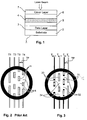
- FIG. 1 an optical storage medium 1 is shown in a cross-section in a simplified manner.
- the optical storage medium 1 is for example a read-only (ROM) optical disc.
- a data layer 3 is arranged on a substrate 2 of the optical storage medium 1, which may comprise a reflective metallic layer, for example an aluminum layer.
- the data layer 3 has a data structure consisting of marks and spaces arranged on essentially parallel tracks. In the case of a ROM disc, the marks and spaces consist of pits and lands, the pits being molded or embossed on the surface of substrate 2 representing the data layer 3, and the reflective metallic layer covers the data layer 3.
- a first dielectric layer 5 On the data layer 3 a first dielectric layer 5 is arranged, on which a nonlinear layer 4 is disposed for providing the function of a mask layer for utilizing a super-resolution effect.
- the nonlinear layer 4 comprises in particular a super-resolution structure, e.g. a super-resolution near-field structure (Super-RENS).
- the optical storage medium 1 is for example an optical disc having a size similar to a DVDs, CDs and Blu-ray discs.
- a second dielectric layer 6 is disposed above the nonlinear layer 4 .
- a cover layer 7 is disposed on the second dielectric layer 5 as a protective layer.
- a laser beam is applied in this embodiment from the top of the storage medium 1, penetrating first the cover layer 7.
- the first and second dielectric layers 5, 6 comprise for example the material ZnS-SiO 2 .
- the substrate 2 and the cover layer 7 may consist of a plastic material, as known from DVDs and CDs.
- the reflective metallic layer may be omitted, when a super-resolution near field structure is used, which does not provide an increase in transmittance due to a heating effect, but works with another nonlinear effect, for example utilizes an effect providing an increased reflectivity of the nonlinear layer 4 when irradiated with a laser beam.
- the layers of the storage medium 1 are arranged in particular as a layer stack.
- the resolution of a pickup for reading of the data can be increased in track direction, for example by a factor of two to four. This allows a reduction of the size of the marks and spaces of the tracks in track direction. But the super-resolution effect as such does not allow to reduce the track pitch below the diffraction limit of ⁇ /2*NA of the pickup.
- a push-pull effect is used for the tracking regulation of the pickup, the reduction of the track pitch is limited by the fact that the 1 st order refracted beams have to be collected by the objective lens of the pickup. Otherwise there is no push-pull signal, because this signal is generated by the interference of the 0 th order and the 1 st order beams as reflected from the optical storage medium.
- this occurs at a track pitch of about 280 nm, the diffraction limit ⁇ /2*NA is 238 nm.
- the standard track pitch of a Blu-ray disc is 320 nm.
- FIG. 1 A prior art data structure of an optical storage medium, e.g. a Blu-ray disc, is shown in Fig. 1 in a simplified manner.
- the optical storage medium comprises essentially parallel tracks T1-T4 with same track pitch TP between adjacent tracks.
- a small part of the optical storage medium is shown in magnification showing marks m and spaces s of the tracks T1-T4.
- a 1.7 PP channel modulation code is used for the data structure and the track pitch TP is 320nm.
- a digital data stream for example the data stream of a movie, is converted into marks and spaces of a track, the marks and spaces having a size of 2T up to 8T or 9T, wherein T is the channel bit length having a value of 69nm, 74,5nm or 80nm for the Blu-ray disc.
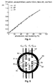
- the marks 31 are enlarged in length and the spaces 32 are shortened in length on a first track, e.g. track T m
- the marks 33 are shortened in length and the spaces 34 are enlarged in length on an adjacent track, tracks T n , T n-1 , with regard to a given channel modulation code, as shown in Fig. 3 .
- Every second track T m , T m+1 , T m+2 etc. comprises therefore enlarged marks and shortened spaces, which tracks are interleaved with tracks T n , T n+1 , T n+2 etc. comprising shortened marks and enlarged spaces.
- Tracks T m and tracks T m+1 are arranged with a distance of 2 TP, where TP is the track pitch between adjacent tracks T n , T m .
- the structure of the marks and spaces changes therefore periodically for consecutive adjacent tracks between marks 31 being enlarged in length and spaces 32 being shortened in length and marks 33 being shortened in length and spaces 34 being enlarged in length.
- the track pitch TP between adjacent tracks can be reduced, in particular below the diffraction limit of ⁇ /2*NA, by still providing a stable tracking regulation.
- An optical pickup for reading of the data still sees the periodic structure of 2 TP on the optical disc even when the track pitch TP is below the diffraction limit of ⁇ /2*NA, as long as 2 TP is above the diffraction limit of the pickup, or more specifically, the track pitch TP is large enough to generate a minimum push-pull signal level, e.g. with an amplitude of at least 10%. This allows in theory to increase the data density up to a factor of 2 in radial direction.
- push/pull signals PP are shown for an optical disc comprising a track structure in accordance with figure 3 .
- the amplitudes of the push/pull signals increase with increased extension and shortening and is zero without pit extension and land shortening.
- the push/pull signals PP are essentially independent of the sizes 3T, 5T, 7T of the pits and lands.
- An extension and shortening of pits and lands of 20% corresponding with a duty cycle of 60% provides a push/pull signal of about 0,2, which is sufficient for providing a stable push/pull tracking regulation.
- the track pitch of 240nm provides an increase in data density of 1/3 with regard to the Blu-ray disc standard having a track pitch of 320nm.
- marks 51 are enlarged in length and in width and spaces 52 are reduced in length for tracks T' m and marks 53 are reduced in length and in width and spaces 54 are enlarged in length for tracks T' n as shown in figure 5 .
- the mark 55 of track T' m+1 for example contains extensions 56 for enlarging the length and contains extensions 57 for enlarging the width, with regard to a defined channel bit length of a given channel modulation code.
- a channel modulation code may be used including marks and spaces with sizes from 2T to 8T, where T is the channel bit length, similar to the Blue/Ray disc channel modulation code.
- T is the channel bit length, similar to the Blue/Ray disc channel modulation code.
- For the channel bit length for example a length of 40nm or 50nm may be used.
- the structure of the marks and spaces changes therefore periodically for consecutive adjacent tracks T' m , T' n between enlarged marks and shortened spaces, and reduced marks and enlarged spaces.
- the track pitch TP between adjacent tracks T' m , T' n can be reduced correspondingly, in particular below the diffraction limit of ⁇ /2*NA of a pickup, by still providing a stable tracking regulation.
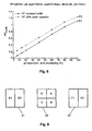
- the track structure T' m , T' n of Fig. 5 provides an increased push/pull signal for the same track pitch TP with regard to the track structure of Fig. 3 , as shown in figure 6.
- the push/pull signal P1 shows the push/pull signal in dependency of the pit extension and land shortening of tracks T m and pit shortening and land extension of tracks T n for 5T pits, wherein the pits of all tracks have the same width, corresponding with the embodiment of fig. 3 .
- the push/pull signal P2 corresponds with the parameters for the push/pull signal P1, but includes pits, which are enlarged in addition in width for tracks T' m , and pits reduced in addition in width for tracks T' n , corresponding with the embodiment of fig. 5 , the widths variation being +/- 20% with regard to the width of the pits as used for the simulation for the push/pull signal P1.
- the additional variation of the width provides an increase of the push/pull signal.
- An increase of more than a factor of 2 can be obtained for the situation, when tracks have a pit extension and land shortening of 10% for tracks T' m and corresponding pit shortening and land extension for tracks T' n .
- an increased push/pull signal can be obtained therefore, or alternatively, the track pitch can be reduced further for providing an increased data density of the optical storage medium.
- the modification of the pits and lands with regard,to the length has the disadvantage that the bit error rate increases when the modification is too large. But a modification of 10% would already provide a push/pull signal of more than 0,2 according to figure 6 , which would be sufficient already for providing a stable tracking regulation. A modification of 10% corresponding with a duty cycle of 55% is particularly still compliant with the Blu-ray disc specification because the respective jitter contribution is only 5%.
- the reduction of the width of marks of tracks T' m and increase of the width of marks T' n has the disadvantage that the HF data signal modulation is lower for the tracks having marks with reduced width and also for tracks having marks with increased width. But a modification of 20% in width as taken into account for the simulation of Fig. 6 still provides a sufficient HF signal.
- a modification of the length and width of marks and including a modification of the length of spaces By using a modification of the length and width of marks and including a modification of the length of spaces, a reduction of the track pitch of the optical storage medium by a factor of 2 can be easily obtained, for providing an increased data capacity.
- the production can be made by using a stamper comprising corresponding pits and lands.
- the stamper can be provided by manufacturing a master disc, which contains pits and lands recorded on the master disc for example by using electron beam mastering.
- the track structures according to figures 3 and 5 may be arranged on an optical disc in form of spirals, as known from a DVD or a Blu-Ray disc, or in form of circular rings or segments of circular rings, as known from a DVD-RAM.
- FIG 3a an embodiment of a track structure is shown in a simplified manner, in which tracks T21 - T24, ... are represented by one spiral S1 on an optical disc.
- the spiral S1 consists of segments Z1, Z2, ...
- the spiral S1 is partitioned into sequences Z1, Z3, Z5, ..., corresponding with tracks T m or T' m , indicated by fat line segments, and interleaved sequences Z2, Z4, ... corresponding with tracks T n or T' n , indicated by thin line segments.
- the length of each of the segments Z1 - Z5 has the length of one revolution respectively 360°, the requirement is fulfilled, that structure of the marks and spaces changes periodically for consecutive adjacent tracks, as shown in figure 7a .
- FIG 7b Another preferred embodiment of the optical storage medium 1 is shown in figure 7b in a simplified manner, in which tracks T21'-T24', etc. are arranged as two spirals S2, S3 on an optical disc.
- the first spiral S2 comprises marks and spaces in accordance with tracks T m or T' m and the second spiral S3 comprises marks and spaces in accordance with tracks T n or T' n .
- the first spiral S2 is interleaved with the second spiral S3 such, that the tracks T21', T23' belong to the first spiral S2 and the tracks T22', T24' belong to the second spiral S3.
- An apparatus for reading of data of an optical storage medium in accordance with Fig. 2 comprises a pickup with a laser, a detector unit, and an objective lens for reading data from the optical storage medium, a tracking regulation and a data processing unit for decoding data of the tracks T m and T n , and/or of the tracks T' m and T' n in accordance with the embodiments of Fig. 3 or 5 .
- the data processing unit may include a compensation means for compensating the reduction and extension of the lengths of the marks and spaces for a better recognition and for reducing the jitter of the HF signal.
- the data processing unit includes advantageously also a selection means for selecting spiral S2 or spiral S3 in accordance with the embodiment of Fig. 7b , which may be made for example by changing the polarity of the tracking error signal.
- the apparatus uses advantageously a three beam optical pickup, providing a center beam for reading of the data tracks and providing two satellite beams for utilizing a differential push-pull tracking method.
- a lower laser power can be selected with regard to the laser power of the center beam, for example the intensity of the two satellite beams is each smaller than 50% of the intensity of the main beam, because no super-resolution effect is required for generating the push-pull tracking signal.
- a conventional differential push-pull grating can be used within the pickup to generate the three beams, wherein the satellite beams have a lower power than the center beam, and wherein the radial distance of the spots as provided on the optical disc is -TP between the first satellite beam and the center beam and +TP between the center beam and the second satellite beam.
- a detector unit which can be used advantageously for providing such a push-pull tracking signal, as well as for providing a data signal and a focus error signal, is shown in Fig. 8 .
- the detector unit comprises a four-quadrant detector 20 with four segments A, B, C, D for detecting light from the center beam as reflected from the optical disc.
- a second detector 21 is provided for the reflected light from the first satellite beam and for reflected light from the second satellite beam a third detector 22, which are each split into two halves with regard to the radial direction of the optical disc.
- Detector 21 is split into two equal segments E1, E2 and detector 22 into two equal segments F1, F2, and the geometrical arrangement of the detectors 20-22 inside the pickup is made such that the reflected light from the main beam is centered on detector 20, reflected light from the first satellite beam centered on detector 21 and reflected light from the second satellite beam centered on detector 22.
- the factor ⁇ is needed to compensate the lower signals from the satellite detectors E1, E2, F1, F2 which are caused by the lower amplitudes of the satellite beams.
- the four segments A-D are further used to provide the HF data signal and the focus error signal for focus regulation.
- the apparatus For reading the data of an optical ROM disc in accordance with the embodiment shown in Fig. 7b , the apparatus reads for example the first spiral S2 up to the end, and then the second spiral S3. For this the pickup has to be repositioned to the beginning of the second spiral S3. Alternatively, the pickup reads a certain number of tracks of spiral S2, then the actuator of the pickup moves back a few tracks, preferably without moving the whole pickup, and reads the same number of tracks of spiral S3 and so on. By this approach a quasi-continuous reading of the whole disc can be realized.
- the track structures of the invention as explained with regard to Figs. 3 and 5 can be applied in particular to a Super-RENS ROM disc, comprising a mask layer with a super resolution structure.
- the track pitch is advantageously below 240 nm for use with an optical pickup having a laser emitting light with a wavelength of e.g. about 405 nm.
- the track structures of the invention may be applied for example also to other present or future optical discs not including a nonlinear layer for a reduction of the track pitch. The invention resides therefore in the claims herein after appended.
Landscapes
- Optical Recording Or Reproduction (AREA)
- Optical Record Carriers And Manufacture Thereof (AREA)
Claims (9)
- Support de stockage optique (1) comprenant une couche de substrat (2) et une couche de données (3) disposée sur la couche de substrat (2), la couche de données (3) dotée d'une structure de données marque/espace agencée en pistes (Tm, Tn; T'm, T'n), le pas transversal (TP) entre deux pistes adjacentes (Tm, Tn; T'm, T'n) étant situé dans une plage ou sous une limite de diffraction de 2*NA d'un capteur de lecture des données, caractérisé en ce que, pour les pistes consécutives adjacentes (Tm, Tn; T'm, T'n), la structure des marques et des espaces change de façon périodique entre les marques (31, 51), qui sont agrandies en longueur et en largeur, et les espaces (31, 52), qui sont raccourcis en longueur, et les marques (33, 53), qui sont raccourcies en longueur et en largeur, et les espaces (34, 54), qui sont agrandis en longueur, les marques et les espaces étant agrandis et raccourcis en longueur par rapport à une longueur de bit de canal définie d'un code de modulation d'un canal donné, et le support de stockage optique est un disque optique en lecture-seule comprenant des creux et des méplats en lieu de marques et espaces.
- Le support de stockage optique selon la revendication 1, dans lequel les marques (31, 51) sont agrandies en longueur et les espaces (32, 52) sont rétrécis en longueur équivalente à un premier type de pistes (Tm; T'm) et les marques (33, 53) sont raccourcies en longueur et les espaces (34, 54) sont agrandis en longueur de pistes entrelacées (Tn ; T'n) de telle sorte qu'un signal d'erreur de piste push-pull avec une amplitude située dans un intervalle de 0,10 à 0,35 est obtenu.
- Le support de stockage optique selon la revendication 1 ou 2, dans lequel les pistes (Tm; T'm) dotées de creux agrandis en longueurs et de méplats raccourcis en longueur fournissent des pistes de type sillon ayant des creux représentant un cycle de service creux/méplat dans une plage située entre 55 % et 70 % et des pistes (Tn; T'n) dotées de creux raccourcis en longueur et de méplats agrandis en longueur, fournissent des pistes de type sillon dotées de méplats représentants un cycle de service creux/méplat dans une plage située entre 55 % et 70%.
- Le support de stockage optique selon l'une des revendications précédentes, dans lequel le pas transversal (TP) entre des pistes adjacentes (Tm, Tn; T'm, T'n) se trouve dans une plage située entre f /λ 2*NA et λ/4*NA.
- Support de stockage optique selon l'une des revendications précédentes, comprenant une couche non-linéaire (4) dotée d'une structure à super résolution agencée sur la couche de données (3) afin de produire un effet de super-résolution.
- Appareil comprenant un capteur doté d'un laser, une unité de détection (20-22) et une lentille de focalisation afin de lire les données d'un support de stockage optique (1) selon la revendication 5, et comprenant une unité de traitement des données afin de décoder les données des pistes (Tm; T'm) disposant de marques (31, 51) agrandies en longueur et en largeur, et d'espaces (32, 52) raccourcis en longueur, et de pistes (Tn; T'n) dotées de marques (33, 53) raccourcies en longueur et en largeur, et d'espaces (34, 54) agrandis en longueur, dans lequel le capteur produit un faisceau central et deux faisceaux satellites afin de fournir un signal de données HF et un signal d'erreur de suivi, les trois faisceaux étant dirigés par la lentille de focalisation vers le support de stockage optique, et la lumière réfléchie sur le support de stockage optique étant guidée vers l'unité de détection (20, 22), et le faisceau central est réglable sur une piste (Tm) du support de stockage optique (1) pour la lecture des données, et dans lequel un premier des deux faisceaux satellites est réglé vers une première piste adjacente (Tn-1), et le second des faisceaux satellites est réglé vers la seconde piste adjacente (Tn) lorsque le faisceau central est réglé vers ladite piste (Tm), et où l'intensité des deux faisceaux satellites est pour chacun inférieure à 50 % de l'intensité du faisceau principal.
- L'appareil selon la revendication 6, dans lequel l'unité de détection comprend un détecteur central (20) pour la détection de la lumière réfléchie à partir du faisceau central et de deux détecteurs satellites (21, 22) pour la détection de la lumière réfléchie à partir des faisceaux satellites, les deux détecteurs satellites (21, 22) étant chacun divisés en deux segments (E1, E2, F1, F2), et le capteur produisant un signal de piste push-pull afin de repérer les réglages en réponse au deux détecteurs satellites (21, 22), ou produisant un signal de piste push-pull afin de repérer les réglage en réponse au détecteur central (20).
- L'appareil selon la revendication 7, dans lequel le signal d'erreur de piste (TE) est calculé en prenant en compte la relation TE= (el-e2) + (f1-f2), e1, e2, f1, f2 étant des signaux électriques en provenance des quatre segments (E1, E2, F1, F2) des deux détecteurs satellites (21, 22).
- L'appareil selon l'une des revendications 6 à 8, dans lequel l'unité de traitement des données comprend un moyen de compensation pour la compensation de la réduction et de l'extension des longueurs des marques et des espaces.
Priority Applications (1)
| Application Number | Priority Date | Filing Date | Title |
|---|---|---|---|
| EP10715827.1A EP2425429B1 (fr) | 2009-04-28 | 2010-04-26 | Support de stockage optique comprenant des pistes avec des dimensions de marques modifiées et appareil correspondant pour la lecture de données |
Applications Claiming Priority (4)
| Application Number | Priority Date | Filing Date | Title |
|---|---|---|---|
| EP09305364A EP2246854A1 (fr) | 2009-04-28 | 2009-04-28 | Support de stockage optique comprenant des codes de modulation différents et appareil correspondant pour la lecture de données |
| EP09305699A EP2287838A1 (fr) | 2009-07-23 | 2009-07-23 | Support de stockage optique comprenant des pistes avec des dimensions de marques modifiées et appareil correspondant pour la lecture de données |
| PCT/EP2010/055510 WO2010125015A1 (fr) | 2009-04-28 | 2010-04-26 | Support de stockage optique comprenant des pistes aux dimensions de marque modifiées, et appareil respectif de lecture de données |
| EP10715827.1A EP2425429B1 (fr) | 2009-04-28 | 2010-04-26 | Support de stockage optique comprenant des pistes avec des dimensions de marques modifiées et appareil correspondant pour la lecture de données |
Publications (2)
| Publication Number | Publication Date |
|---|---|
| EP2425429A1 EP2425429A1 (fr) | 2012-03-07 |
| EP2425429B1 true EP2425429B1 (fr) | 2014-06-11 |
Family
ID=42237382
Family Applications (1)
| Application Number | Title | Priority Date | Filing Date |
|---|---|---|---|
| EP10715827.1A Not-in-force EP2425429B1 (fr) | 2009-04-28 | 2010-04-26 | Support de stockage optique comprenant des pistes avec des dimensions de marques modifiées et appareil correspondant pour la lecture de données |
Country Status (3)
| Country | Link |
|---|---|
| US (1) | US8493832B2 (fr) |
| EP (1) | EP2425429B1 (fr) |
| WO (1) | WO2010125015A1 (fr) |
Families Citing this family (1)
| Publication number | Priority date | Publication date | Assignee | Title |
|---|---|---|---|---|
| US9412408B2 (en) * | 2013-06-07 | 2016-08-09 | Sharp Kabushiki Kaisha | Optical information recording medium having first and second pit row of identical reflectance |
Family Cites Families (14)
| Publication number | Priority date | Publication date | Assignee | Title |
|---|---|---|---|---|
| US5740141A (en) * | 1993-03-09 | 1998-04-14 | Matsushita Electric Industrial Co., Ltd. | Signal processing device for an optical information reproducing apparatus |
| IL138671A (en) | 1999-01-27 | 2005-12-18 | Koninkl Philips Electronics Nv | Record carrier, playback device and method of recording information |
| JP2004227622A (ja) * | 2003-01-20 | 2004-08-12 | Toshiba Corp | 光記録媒体および光記録再生方法 |
| JPWO2005029479A1 (ja) * | 2003-09-18 | 2006-11-30 | 松下電器産業株式会社 | 記録再生方法および記録再生装置 |
| US20070008840A1 (en) * | 2003-10-09 | 2007-01-11 | Koninklijke Philips Electronics N.V. | Optical disc having focus offset area |
| US20050286401A1 (en) * | 2004-06-29 | 2005-12-29 | Tdk Corporation | ROM-type optical recording medium and stamper for manufacturing ROM-type optical recording medium |
| JP2007323773A (ja) * | 2006-06-02 | 2007-12-13 | Toshiba Corp | 光ディスク、情報記録方法、情報再生方法、およびディスクドライブ |
| CN101536095B (zh) | 2006-10-16 | 2011-06-08 | 汤姆森特许公司 | 包括具有正型和负型标记的道的光学存储介质、用于制造该光学存储介质的压模和制造方法 |
| US7804752B2 (en) * | 2007-02-05 | 2010-09-28 | Hewlett-Packard Development Company, L.P. | Focal offset recording system and method |
| EP1968048A1 (fr) | 2007-03-08 | 2008-09-10 | Deutsche Thomson OHG | Support de stockage optique et appareil de lecture des données respectives |
| JP4903081B2 (ja) * | 2007-05-17 | 2012-03-21 | 株式会社日立製作所 | 光ディスク媒体及びトラッキング方法 |
| EP2009626A1 (fr) | 2007-06-29 | 2008-12-31 | Deutsche Thomson OHG | Appareil comprenant une unité de capture fournissant trois faisceaux de données de lecture depuis ou écrivant des données sur un support de stockage optique et support de stockage optique correspondant |
| JP4778940B2 (ja) | 2007-09-20 | 2011-09-21 | 株式会社日立製作所 | 光情報再生方法及び光情報再生装置 |
| EP2385524A1 (fr) * | 2010-05-07 | 2011-11-09 | Thomson Licensing | Disque optique doté d'une sensibilité accrue aux creux et sommets de super résolution |
-
2010
- 2010-04-26 EP EP10715827.1A patent/EP2425429B1/fr not_active Not-in-force
- 2010-04-26 WO PCT/EP2010/055510 patent/WO2010125015A1/fr not_active Ceased
- 2010-04-26 US US13/138,905 patent/US8493832B2/en not_active Expired - Fee Related
Also Published As
| Publication number | Publication date |
|---|---|
| US8493832B2 (en) | 2013-07-23 |
| US20120124601A1 (en) | 2012-05-17 |
| WO2010125015A1 (fr) | 2010-11-04 |
| EP2425429A1 (fr) | 2012-03-07 |
Similar Documents
| Publication | Publication Date | Title |
|---|---|---|
| US20100027406A1 (en) | Optical storage medium comprising tracks with different width and respective production method | |
| US8027241B2 (en) | Optical storage medium, mastering method and apparatus for reading of respective data | |
| US8023395B2 (en) | Optical storage medium comprising tracks with positive and negative marks, and stampers and production methods for manufacturing of the optical storage medium | |
| EP2009627B1 (fr) | Appareil comprenant une unité de capture fournissant trois faisceaux de données de lecture depuis ou écrivant des données sur un support de stockage optique et support de stockage optique correspondant | |
| EP2260489B1 (fr) | Support de stockage optique comprenant une couche de données à multiples niveaux | |
| US8259558B2 (en) | Optical storage medium and apparatus for reading of respective data | |
| EP2425429B1 (fr) | Support de stockage optique comprenant des pistes avec des dimensions de marques modifiées et appareil correspondant pour la lecture de données | |
| EP2569768B1 (fr) | Support de stockage optique comprenant une compensation de décalage de phase | |
| EP2287838A1 (fr) | Support de stockage optique comprenant des pistes avec des dimensions de marques modifiées et appareil correspondant pour la lecture de données | |
| EP2246854A1 (fr) | Support de stockage optique comprenant des codes de modulation différents et appareil correspondant pour la lecture de données | |
| US8213278B2 (en) | System comprising an optical disc and an apparatus for reading of respective data | |
| KR20080021120A (ko) | 3 스폿 반경방향 트랙킹을 하는 광학계 | |
| US20090279408A1 (en) | Optical data recording/reproducing system picking up multiple tracks between guard bands | |
| EP2372709A1 (fr) | Support de stockage optique comprenant une couche de données avec une structure de données à marques/espaces inversée/non inversée | |
| EP2346040A1 (fr) | Support de stockage optique comprenant une couche à super résolution et une couche de données en lecture seule |
Legal Events
| Date | Code | Title | Description |
|---|---|---|---|
| PUAI | Public reference made under article 153(3) epc to a published international application that has entered the european phase |
Free format text: ORIGINAL CODE: 0009012 |
|
| 17P | Request for examination filed |
Effective date: 20110916 |
|
| AK | Designated contracting states |
Kind code of ref document: A1 Designated state(s): AT BE BG CH CY CZ DE DK EE ES FI FR GB GR HR HU IE IS IT LI LT LU LV MC MK MT NL NO PL PT RO SE SI SK SM TR |
|
| DAX | Request for extension of the european patent (deleted) | ||
| REG | Reference to a national code |
Ref country code: DE Ref legal event code: R079 Ref document number: 602010016633 Country of ref document: DE Free format text: PREVIOUS MAIN CLASS: G11B0007013000 Ipc: G11B0007240790 |
|
| RIC1 | Information provided on ipc code assigned before grant |
Ipc: G11B 7/24 20130101ALI20130820BHEP Ipc: G11B 7/24085 20130101ALI20130820BHEP Ipc: G11B 7/09 20060101ALI20130820BHEP Ipc: G11B 7/24079 20130101AFI20130820BHEP |
|
| GRAP | Despatch of communication of intention to grant a patent |
Free format text: ORIGINAL CODE: EPIDOSNIGR1 |
|
| INTG | Intention to grant announced |
Effective date: 20131219 |
|
| GRAS | Grant fee paid |
Free format text: ORIGINAL CODE: EPIDOSNIGR3 |
|
| GRAA | (expected) grant |
Free format text: ORIGINAL CODE: 0009210 |
|
| AK | Designated contracting states |
Kind code of ref document: B1 Designated state(s): AT BE BG CH CY CZ DE DK EE ES FI FR GB GR HR HU IE IS IT LI LT LU LV MC MK MT NL NO PL PT RO SE SI SK SM TR |
|
| REG | Reference to a national code |
Ref country code: GB Ref legal event code: FG4D |
|
| REG | Reference to a national code |
Ref country code: CH Ref legal event code: EP |
|
| REG | Reference to a national code |
Ref country code: DE Ref legal event code: R084 Ref document number: 602010016633 Country of ref document: DE |
|
| REG | Reference to a national code |
Ref country code: IE Ref legal event code: FG4D |
|
| REG | Reference to a national code |
Ref country code: AT Ref legal event code: REF Ref document number: 672582 Country of ref document: AT Kind code of ref document: T Effective date: 20140715 |
|
| REG | Reference to a national code |
Ref country code: DE Ref legal event code: R096 Ref document number: 602010016633 Country of ref document: DE Effective date: 20140724 |
|
| REG | Reference to a national code |
Ref country code: DE Ref legal event code: R084 Ref document number: 602010016633 Country of ref document: DE Effective date: 20140614 |
|
| PG25 | Lapsed in a contracting state [announced via postgrant information from national office to epo] |
Ref country code: LT Free format text: LAPSE BECAUSE OF FAILURE TO SUBMIT A TRANSLATION OF THE DESCRIPTION OR TO PAY THE FEE WITHIN THE PRESCRIBED TIME-LIMIT Effective date: 20140611 Ref country code: FI Free format text: LAPSE BECAUSE OF FAILURE TO SUBMIT A TRANSLATION OF THE DESCRIPTION OR TO PAY THE FEE WITHIN THE PRESCRIBED TIME-LIMIT Effective date: 20140611 Ref country code: NO Free format text: LAPSE BECAUSE OF FAILURE TO SUBMIT A TRANSLATION OF THE DESCRIPTION OR TO PAY THE FEE WITHIN THE PRESCRIBED TIME-LIMIT Effective date: 20140911 Ref country code: GR Free format text: LAPSE BECAUSE OF FAILURE TO SUBMIT A TRANSLATION OF THE DESCRIPTION OR TO PAY THE FEE WITHIN THE PRESCRIBED TIME-LIMIT Effective date: 20140912 |
|
| REG | Reference to a national code |
Ref country code: NL Ref legal event code: VDEP Effective date: 20140611 |
|
| REG | Reference to a national code |
Ref country code: AT Ref legal event code: MK05 Ref document number: 672582 Country of ref document: AT Kind code of ref document: T Effective date: 20140611 |
|
| REG | Reference to a national code |
Ref country code: LT Ref legal event code: MG4D |
|
| PG25 | Lapsed in a contracting state [announced via postgrant information from national office to epo] |
Ref country code: HR Free format text: LAPSE BECAUSE OF FAILURE TO SUBMIT A TRANSLATION OF THE DESCRIPTION OR TO PAY THE FEE WITHIN THE PRESCRIBED TIME-LIMIT Effective date: 20140611 Ref country code: SE Free format text: LAPSE BECAUSE OF FAILURE TO SUBMIT A TRANSLATION OF THE DESCRIPTION OR TO PAY THE FEE WITHIN THE PRESCRIBED TIME-LIMIT Effective date: 20140611 Ref country code: LV Free format text: LAPSE BECAUSE OF FAILURE TO SUBMIT A TRANSLATION OF THE DESCRIPTION OR TO PAY THE FEE WITHIN THE PRESCRIBED TIME-LIMIT Effective date: 20140611 |
|
| PG25 | Lapsed in a contracting state [announced via postgrant information from national office to epo] |
Ref country code: EE Free format text: LAPSE BECAUSE OF FAILURE TO SUBMIT A TRANSLATION OF THE DESCRIPTION OR TO PAY THE FEE WITHIN THE PRESCRIBED TIME-LIMIT Effective date: 20140611 Ref country code: RO Free format text: LAPSE BECAUSE OF FAILURE TO SUBMIT A TRANSLATION OF THE DESCRIPTION OR TO PAY THE FEE WITHIN THE PRESCRIBED TIME-LIMIT Effective date: 20140611 Ref country code: ES Free format text: LAPSE BECAUSE OF FAILURE TO SUBMIT A TRANSLATION OF THE DESCRIPTION OR TO PAY THE FEE WITHIN THE PRESCRIBED TIME-LIMIT Effective date: 20140611 Ref country code: CZ Free format text: LAPSE BECAUSE OF FAILURE TO SUBMIT A TRANSLATION OF THE DESCRIPTION OR TO PAY THE FEE WITHIN THE PRESCRIBED TIME-LIMIT Effective date: 20140611 Ref country code: SK Free format text: LAPSE BECAUSE OF FAILURE TO SUBMIT A TRANSLATION OF THE DESCRIPTION OR TO PAY THE FEE WITHIN THE PRESCRIBED TIME-LIMIT Effective date: 20140611 Ref country code: PT Free format text: LAPSE BECAUSE OF FAILURE TO SUBMIT A TRANSLATION OF THE DESCRIPTION OR TO PAY THE FEE WITHIN THE PRESCRIBED TIME-LIMIT Effective date: 20141013 |
|
| PG25 | Lapsed in a contracting state [announced via postgrant information from national office to epo] |
Ref country code: PL Free format text: LAPSE BECAUSE OF FAILURE TO SUBMIT A TRANSLATION OF THE DESCRIPTION OR TO PAY THE FEE WITHIN THE PRESCRIBED TIME-LIMIT Effective date: 20140611 Ref country code: NL Free format text: LAPSE BECAUSE OF FAILURE TO SUBMIT A TRANSLATION OF THE DESCRIPTION OR TO PAY THE FEE WITHIN THE PRESCRIBED TIME-LIMIT Effective date: 20140611 Ref country code: IS Free format text: LAPSE BECAUSE OF FAILURE TO SUBMIT A TRANSLATION OF THE DESCRIPTION OR TO PAY THE FEE WITHIN THE PRESCRIBED TIME-LIMIT Effective date: 20141011 Ref country code: AT Free format text: LAPSE BECAUSE OF FAILURE TO SUBMIT A TRANSLATION OF THE DESCRIPTION OR TO PAY THE FEE WITHIN THE PRESCRIBED TIME-LIMIT Effective date: 20140611 |
|
| REG | Reference to a national code |
Ref country code: DE Ref legal event code: R097 Ref document number: 602010016633 Country of ref document: DE |
|
| PLBE | No opposition filed within time limit |
Free format text: ORIGINAL CODE: 0009261 |
|
| STAA | Information on the status of an ep patent application or granted ep patent |
Free format text: STATUS: NO OPPOSITION FILED WITHIN TIME LIMIT |
|
| PG25 | Lapsed in a contracting state [announced via postgrant information from national office to epo] |
Ref country code: IT Free format text: LAPSE BECAUSE OF FAILURE TO SUBMIT A TRANSLATION OF THE DESCRIPTION OR TO PAY THE FEE WITHIN THE PRESCRIBED TIME-LIMIT Effective date: 20140611 Ref country code: DK Free format text: LAPSE BECAUSE OF FAILURE TO SUBMIT A TRANSLATION OF THE DESCRIPTION OR TO PAY THE FEE WITHIN THE PRESCRIBED TIME-LIMIT Effective date: 20140611 |
|
| 26N | No opposition filed |
Effective date: 20150312 |
|
| REG | Reference to a national code |
Ref country code: DE Ref legal event code: R097 Ref document number: 602010016633 Country of ref document: DE Effective date: 20150312 |
|
| PG25 | Lapsed in a contracting state [announced via postgrant information from national office to epo] |
Ref country code: BE Free format text: LAPSE BECAUSE OF FAILURE TO SUBMIT A TRANSLATION OF THE DESCRIPTION OR TO PAY THE FEE WITHIN THE PRESCRIBED TIME-LIMIT Effective date: 20140611 |
|
| PG25 | Lapsed in a contracting state [announced via postgrant information from national office to epo] |
Ref country code: SI Free format text: LAPSE BECAUSE OF FAILURE TO SUBMIT A TRANSLATION OF THE DESCRIPTION OR TO PAY THE FEE WITHIN THE PRESCRIBED TIME-LIMIT Effective date: 20140611 |
|
| PGFP | Annual fee paid to national office [announced via postgrant information from national office to epo] |
Ref country code: DE Payment date: 20150827 Year of fee payment: 6 |
|
| PG25 | Lapsed in a contracting state [announced via postgrant information from national office to epo] |
Ref country code: MC Free format text: LAPSE BECAUSE OF FAILURE TO SUBMIT A TRANSLATION OF THE DESCRIPTION OR TO PAY THE FEE WITHIN THE PRESCRIBED TIME-LIMIT Effective date: 20140611 Ref country code: LU Free format text: LAPSE BECAUSE OF FAILURE TO SUBMIT A TRANSLATION OF THE DESCRIPTION OR TO PAY THE FEE WITHIN THE PRESCRIBED TIME-LIMIT Effective date: 20150426 |
|
| REG | Reference to a national code |
Ref country code: CH Ref legal event code: PL |
|
| GBPC | Gb: european patent ceased through non-payment of renewal fee |
Effective date: 20150426 |
|
| REG | Reference to a national code |
Ref country code: IE Ref legal event code: MM4A |
|
| PG25 | Lapsed in a contracting state [announced via postgrant information from national office to epo] |
Ref country code: GB Free format text: LAPSE BECAUSE OF NON-PAYMENT OF DUE FEES Effective date: 20150426 Ref country code: LI Free format text: LAPSE BECAUSE OF NON-PAYMENT OF DUE FEES Effective date: 20150430 Ref country code: CH Free format text: LAPSE BECAUSE OF NON-PAYMENT OF DUE FEES Effective date: 20150430 |
|
| REG | Reference to a national code |
Ref country code: FR Ref legal event code: ST Effective date: 20151231 |
|
| PG25 | Lapsed in a contracting state [announced via postgrant information from national office to epo] |
Ref country code: FR Free format text: LAPSE BECAUSE OF NON-PAYMENT OF DUE FEES Effective date: 20150430 |
|
| PG25 | Lapsed in a contracting state [announced via postgrant information from national office to epo] |
Ref country code: IE Free format text: LAPSE BECAUSE OF NON-PAYMENT OF DUE FEES Effective date: 20150426 |
|
| REG | Reference to a national code |
Ref country code: DE Ref legal event code: R119 Ref document number: 602010016633 Country of ref document: DE |
|
| PG25 | Lapsed in a contracting state [announced via postgrant information from national office to epo] |
Ref country code: MT Free format text: LAPSE BECAUSE OF FAILURE TO SUBMIT A TRANSLATION OF THE DESCRIPTION OR TO PAY THE FEE WITHIN THE PRESCRIBED TIME-LIMIT Effective date: 20140611 |
|
| PG25 | Lapsed in a contracting state [announced via postgrant information from national office to epo] |
Ref country code: DE Free format text: LAPSE BECAUSE OF NON-PAYMENT OF DUE FEES Effective date: 20161101 |
|
| PG25 | Lapsed in a contracting state [announced via postgrant information from national office to epo] |
Ref country code: HU Free format text: LAPSE BECAUSE OF FAILURE TO SUBMIT A TRANSLATION OF THE DESCRIPTION OR TO PAY THE FEE WITHIN THE PRESCRIBED TIME-LIMIT; INVALID AB INITIO Effective date: 20100426 Ref country code: BG Free format text: LAPSE BECAUSE OF FAILURE TO SUBMIT A TRANSLATION OF THE DESCRIPTION OR TO PAY THE FEE WITHIN THE PRESCRIBED TIME-LIMIT Effective date: 20140611 Ref country code: SM Free format text: LAPSE BECAUSE OF FAILURE TO SUBMIT A TRANSLATION OF THE DESCRIPTION OR TO PAY THE FEE WITHIN THE PRESCRIBED TIME-LIMIT Effective date: 20140611 |
|
| PG25 | Lapsed in a contracting state [announced via postgrant information from national office to epo] |
Ref country code: CY Free format text: LAPSE BECAUSE OF FAILURE TO SUBMIT A TRANSLATION OF THE DESCRIPTION OR TO PAY THE FEE WITHIN THE PRESCRIBED TIME-LIMIT Effective date: 20140611 |
|
| PG25 | Lapsed in a contracting state [announced via postgrant information from national office to epo] |
Ref country code: TR Free format text: LAPSE BECAUSE OF FAILURE TO SUBMIT A TRANSLATION OF THE DESCRIPTION OR TO PAY THE FEE WITHIN THE PRESCRIBED TIME-LIMIT Effective date: 20140611 |
|
| PG25 | Lapsed in a contracting state [announced via postgrant information from national office to epo] |
Ref country code: MK Free format text: LAPSE BECAUSE OF FAILURE TO SUBMIT A TRANSLATION OF THE DESCRIPTION OR TO PAY THE FEE WITHIN THE PRESCRIBED TIME-LIMIT Effective date: 20140611 |