EP2425695A1 - Appareil de travail du sol pouvant être remorqué et doté d'un système hydraulique en vue de renforcer la traction - Google Patents
Appareil de travail du sol pouvant être remorqué et doté d'un système hydraulique en vue de renforcer la traction Download PDFInfo
- Publication number
- EP2425695A1 EP2425695A1 EP11005477A EP11005477A EP2425695A1 EP 2425695 A1 EP2425695 A1 EP 2425695A1 EP 11005477 A EP11005477 A EP 11005477A EP 11005477 A EP11005477 A EP 11005477A EP 2425695 A1 EP2425695 A1 EP 2425695A1
- Authority
- EP
- European Patent Office
- Prior art keywords
- hydraulic cylinder
- hydraulic
- tractor
- drawbar
- point tower
- Prior art date
- Legal status (The legal status is an assumption and is not a legal conclusion. Google has not performed a legal analysis and makes no representation as to the accuracy of the status listed.)
- Granted
Links
Images


Classifications
-
- A—HUMAN NECESSITIES
- A01—AGRICULTURE; FORESTRY; ANIMAL HUSBANDRY; HUNTING; TRAPPING; FISHING
- A01B—SOIL WORKING IN AGRICULTURE OR FORESTRY; PARTS, DETAILS, OR ACCESSORIES OF AGRICULTURAL MACHINES OR IMPLEMENTS, IN GENERAL
- A01B59/00—Devices specially adapted for connection between animals or tractors and agricultural machines or implements
- A01B59/06—Devices specially adapted for connection between animals or tractors and agricultural machines or implements for machines mounted on tractors
- A01B59/065—Devices specially adapted for connection between animals or tractors and agricultural machines or implements for machines mounted on tractors for ploughs or like implements
-
- A—HUMAN NECESSITIES
- A01—AGRICULTURE; FORESTRY; ANIMAL HUSBANDRY; HUNTING; TRAPPING; FISHING
- A01B—SOIL WORKING IN AGRICULTURE OR FORESTRY; PARTS, DETAILS, OR ACCESSORIES OF AGRICULTURAL MACHINES OR IMPLEMENTS, IN GENERAL
- A01B63/00—Lifting or adjusting devices or arrangements for agricultural machines or implements
- A01B63/02—Lifting or adjusting devices or arrangements for agricultural machines or implements for implements mounted on tractors
- A01B63/10—Lifting or adjusting devices or arrangements for agricultural machines or implements for implements mounted on tractors operated by hydraulic or pneumatic means
- A01B63/11—Lifting or adjusting devices or arrangements for agricultural machines or implements for implements mounted on tractors operated by hydraulic or pneumatic means for controlling weight transfer between implements and tractor wheels
Definitions
- the present invention relates to a reassembly tillage implement with traction-boosting hydraulics.
- a mounted implement has no transport support and is fully supported by the tractor. During the use of the attached device, it is of course based on soil working elements, such as plowshares from.
- the connection between a three-point tower and the harrow is here either rigid or can be pivoted about a horizontal axis. Vertical rotary axes, as they are necessary for maneuvering, for example, in attached or saddled devices, are not provided here.
- Attached tillage implements are completely on their own wheels, with only the load of the drawbar is borne by the tractor.
- the saddle is a device that partly rests on its own wheels and rests on the towing vehicle on the other part, comparable to a truck semitrailer. For this purpose, the connection of the harrow to a top link and two lower links of the tractor is often selected.
- the object is achieved by a aufattelbares tillage device with traction-enhancing hydraulics.
- the harrow includes for this purpose
- the drawbar is connected to a frame of the harrow. On this frame both the soil working elements and the chassis are arranged.
- the tillage implement comprises a three-point tower connected to the drawbar via a first joint, wherein the first joint between the three-point tower and the drawbar comprises two rotational degrees of freedom.
- a hydraulic cylinder is provided as a hydraulic top link, which engages with one end on the three-point tower and is formed with the other end for connection to a tractor.
- two lower link mountings are formed on the three-point tower.
- Diagonally between the three-point tower and the drawbar is a pendulum support.
- This pendulum support is designed at least for the transmission of tensile forces.
- contraction of the hydraulic cylinder of the three-point tower is loaded in the direction of the tractor to train.
- About the pendulum support transmits this force to the drawbar. This results in a higher axle load on the rear axle of the tractor, which ultimately increases the traction on the rear wheels of the tractor.
- a first axis of rotation of the first joint is arranged horizontally and perpendicular to the pulling direction, and that a second axis of rotation of the first joint is arranged vertically.
- the harrow can be pivoted in a horizontal plane. This facilitates cornering and maneuvering, especially in very long tillage equipment.
- the tillage implement may be raised about the first axis of rotation, or may pivot upward to accommodate large bumps.
- the first end of the pendulum support is fixed by means of a second joint, in particular ball joint, with two rotational degrees of freedom.
- the second end of the pendulum support is preferably rigidly connected or it is fastened by means of a linear guide device with a linear degree of freedom.
- the connection between three-point tower and pendulum support is preferably spaced and above the first joint.
- the connection between pendulum support and drawbar is preferably spaced and behind the first joint.
- the two rotatory degrees of freedom of the second joint allow a Swiveling the harrow both in the horizontal plane and a slight pivoting in the vertical plane.
- the linear guide device on the one hand allows the transmission of tensile forces and allows for compressive forces a linear displacement in a certain frame.
- the pendulum support is designed with a bolt transverse to the pendulum support, wherein the bolt is guided in one or two parallel slots of the linear guide device.
- the invention preferably provides that the hydraulic cylinder is designed to be double-acting.
- Double-acting here means that both hydraulic chambers, that is on both sides of the piston, have a connection for hydraulic lines.
- both chambers must be pressurized, but it can also be a chamber in communication with the tank.
- the hydraulic cylinder regardless of its length, is always subjected to the same pressure.
- the pressure is of course adjustable and must be adjusted depending on the size of the soil cultivator, soil condition, tractor, etc.
- the set pressure remains constant regardless of the contraction state of the hydraulic cylinder.
- the pressure limiting valve is in particular adjustable, controllable or adjustable. Under the pressurized first hydraulic chamber is to understand that which is responsible for the contracting of the hydraulic cylinder. When using a regular differential cylinder, this is the annular chamber.
- the pressure relief valve can be outside sit on the hydraulic cylinder, be arranged between two hydraulic lines or arranged in the piston of the hydraulic cylinder.
- the pressure relief valve is used exclusively for limiting the pressure in the hydraulic cylinder.
- pressure relief valves are provided within the hydraulics of the tractor of course.
- the pressure relief valve used in the invention is preferably arranged outside of the tractor hydraulics and limits only the pressure in the hydraulic cylinder, which serves as a top link.
- the pressure limiting valve is integrated in the hydraulic cylinder, in particular in the piston of the hydraulic cylinder.
- the hydraulic cylinder is designed for connection to the hydraulic circuit of the tractor.
- the hydraulic circuit of the tractor is usually an open hydraulic circuit.
- the traction reinforcement according to the invention works best when the same pressure is always present in the hydraulic cylinder, regardless of its current length.
- a pressure relief valve installed between the two terminals of the hydraulic cylinder.
- the tractor hydraulics is switched onto the hydraulic cylinder, so that always an oil flow to the first hydraulic chamber, in particular ring side, acts.
- the hydraulic cylinder contracts and thus shortens the distance between the tractor-side top link mount and the three-point tower.
- the center of gravity shifts, and the traction on the rear axle of the tractor is increased.
- the force is adjustable, and thus a small force on the hydraulic cylinder is adjustable with small tractors or small devices, the pressure and thus the tensile force of the hydraulic cylinder can be adjusted, controlled or controlled at the pressure relief valve.
- Modern tractors have the Possibility to adjust the amount of oil flow.
- an oil flow of 0.1 to 0.2 l / min is sufficient for the arrangement according to the invention.
- the constant loading of the hydraulic cylinder with the tractor hydraulics and the provision of a pressure limiting valve have significant advantages over the use of a pressure accumulator for loading the hydraulic cylinder.
- the hydraulic cylinder When using a pressure accumulator, the hydraulic cylinder has a different force at each point of length, as long as the system is closed. As a result, the tensile force initiated by the hydraulic cylinder always changes, depending on the position in which the cylinder is currently located. According to the invention this is avoided by the use of the pressure relief valve and the constant connection to the tractor hydraulics.
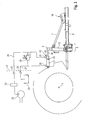
- Fig. 1 to 3 show an embodiment of the invention.
- Fig. 1 shows the tillage device 1 according to the invention, saddled on a tractor 8, in particular tractor or tractor.
- Fig. 2 shows the connection between tractor 8 and harrow 1 in detail.
- Essential components of the tillage device 1 are a drawbar 2, a first joint 3, a three-point tower 4, a hydraulic cylinder 5 as a hydraulic top link and a pendulum support 7.
- the first joint 3 connects the drawbar 2 with the three-point tower 4.
- the pendulum support 7 is diagonal between The three-point tower 4 and the drawbar 2.
- the hydraulic cylinder 5 is arranged in place of a conventional upper link and connects an upper end of the three-point tower 4 with the tractor 8. For further connection between three-point tower 4 and tractor 8 two lower links 6 are arranged.
- the harrow 1 further comprises a frame, landing gear and soil working elements (not shown).
- the frame is connected to the drawbar 2 and carries both the chassis of the tillage implement and the soil working elements.
- Fig. 2 shows a detail Fig. 1
- the three-point tower 4 comprises a standing three-point tower section 10. This is oriented substantially vertically.
- the first joint 3 has a first axis of rotation 11 and a second axis of rotation 12.
- the first axis of rotation 11 is aligned horizontally and perpendicular to the pulling direction of the tractor 8.
- the second axis of rotation 12 is perpendicular to the first axis of rotation 11 and is vertically aligned.
- Further located at the lower end of the three-point tower 4 device-side lower link receptacles 13. On the tractor are two tractor-side lower link receptacles 14.
- a tractor-side upper link mount 16 Between the device-side and the tractor-side upper link mount 15, 16 is the upper link formed as a hydraulic cylinder 5, arranged.
- a second hinge 17 is provided to connect the pendulum support 7 to the three-point tower 4.
- the second joint 17 is designed as a ball joint.
- the second joint 17 is located between the device-side upper link receiver 15 and the first joint 3.
- a linear guide device 18 is provided for connection between drawbar 2 and pendulum support 7, a linear guide device 18 is provided.
- the linear guide device 18 comprises two parallel plates. In these parallel plates two congruent slots 19 are provided.
- a bolt 20 perpendicular to the pendulum support 7. This bolt 20 is guided in the slots 19. This results in a linear degree of freedom in the direction of the oblong holes 19.
- Fig. 3 shows the hydraulics for tensile force reinforcement on the rear axle 9 of the tractor 8.
- the tractor hydraulics includes a hydraulic pump 22, which supplies hydraulic pressure via a hydraulic line to a valve block 24.
- the tractor hydraulics comprise hydraulic couplings 25, on the one hand for connection to the valve block 24 and on the other hand for connection to the tank 23.
- the two hydraulic couplings 25 set the system boundary 21 between the hydraulics the tractor 8 and the hydraulic of the harrow 1 is.
- the hydraulic cylinder 5 of the cultivator 1 comprises a cylinder 32.
- a piston 33 is guided.
- the piston 33 is connected to a piston rod 34.
- the cylinder 32 is connected to the tractor-side upper link receiver 16.
- the piston rod 34 is connected to the device-side upper link receiver 15.
- the piston 33 divides the cylinder 32 into a pressurized first hydraulic chamber 30 and a second hydraulic chamber 31st on.
- the first hydraulic chamber is also referred to as an annular chamber, since the piston rod 34 passes through the first hydraulic chamber 30.
- a first connection 28 is provided on the first hydraulic chamber 30.
- At the second hydraulic chamber 31 is a second port 29.
- the first hydraulic chamber 30 is connected via the first port 28 to the pressure-conducting hydraulic clutch 25.
- the second hydraulic chamber 31 is connected via the connection 29 with the tank-side hydraulic coupling 25 connected.
- a pressure line 26 Between the hydraulic clutch 25 and the first hydraulic chamber 30 is a pressure line 26.
- a tank line 27th Between the second hydraulic chamber 31 and the tank 23 of the tractor hydraulics is a tank line 27th
- the first hydraulic chamber 30 is connected to the second hydraulic chamber 31 via a pressure limiting valve 35.
- the pressure relief valve 35 is adjustable, controllable or adjustable. At an overpressure in the first hydraulic chamber 30 or in the pressure line 26 opens the pressure relief valve 35 and leaves pressure to the second hydraulic chamber 31 and the tank line 27 or directly to the tank 23.
- the pressure relief valve 35 may be arranged at three different locations. It may be arranged between the pressure line 26 and the tank line 27 or between the first connection 28 and the second connection 29 or directly in the piston 33.
- the pressure relief valve 35 is adjusted depending on the desired tensile force, depending on the tractor 8, the harrow 1 and the soil procurement.
Landscapes
- Life Sciences & Earth Sciences (AREA)
- Engineering & Computer Science (AREA)
- Mechanical Engineering (AREA)
- Soil Sciences (AREA)
- Environmental Sciences (AREA)
- Zoology (AREA)
- Lifting Devices For Agricultural Implements (AREA)
- Agricultural Machines (AREA)
Priority Applications (1)
| Application Number | Priority Date | Filing Date | Title |
|---|---|---|---|
| PL11005477T PL2425695T3 (pl) | 2010-09-01 | 2011-07-05 | Półzawieszane narzędzie do uprawy gleby z hydrauliką wzmacniającą siłę pociągową |
Applications Claiming Priority (1)
| Application Number | Priority Date | Filing Date | Title |
|---|---|---|---|
| DE102010036067A DE102010036067A1 (de) | 2010-09-01 | 2010-09-01 | Aufsattelbares Bodenbearbeitungsgerät mit zugkraftverstärkender Hydraulik |
Publications (2)
| Publication Number | Publication Date |
|---|---|
| EP2425695A1 true EP2425695A1 (fr) | 2012-03-07 |
| EP2425695B1 EP2425695B1 (fr) | 2013-06-12 |
Family
ID=44741760
Family Applications (1)
| Application Number | Title | Priority Date | Filing Date |
|---|---|---|---|
| EP11005477.2A Active EP2425695B1 (fr) | 2010-09-01 | 2011-07-05 | Appareil de travail du sol pouvant être remorqué et doté d'un système hydraulique en vue de renforcer la traction |
Country Status (4)
| Country | Link |
|---|---|
| EP (1) | EP2425695B1 (fr) |
| DE (1) | DE102010036067A1 (fr) |
| DK (1) | DK2425695T3 (fr) |
| PL (1) | PL2425695T3 (fr) |
Cited By (1)
| Publication number | Priority date | Publication date | Assignee | Title |
|---|---|---|---|---|
| CN113124974A (zh) * | 2021-04-20 | 2021-07-16 | 山东大学 | 车辆超载检测方法、系统、存储介质及设备 |
Families Citing this family (1)
| Publication number | Priority date | Publication date | Assignee | Title |
|---|---|---|---|---|
| DE102020105931A1 (de) | 2020-03-05 | 2021-09-09 | Erwin Kohn | Vorrichtung zum Verbinden einer landwirtschaftlichen Zugmaschine mit einem Anhänger sowie Ansteuerungsvorrichtung für einen Oberlenker und Verfahren zur Ansteuerung eines Oberlenkers |
Citations (5)
| Publication number | Priority date | Publication date | Assignee | Title |
|---|---|---|---|---|
| US3235286A (en) * | 1963-02-11 | 1966-02-15 | Brown Tractors Ltd | Resilient link for agricultural implements |
| US3246700A (en) * | 1963-07-24 | 1966-04-19 | Int Harvester Co | Implement control means for tractor operated agricultural implements |
| DE1222303B (de) * | 1965-01-07 | 1966-08-04 | Rabewerk Clausing Heinrich | Auf einem Schlepper aufgesatteltes Bodenbearbeitungsgeraet |
| DE1920899A1 (de) * | 1969-04-24 | 1970-11-12 | Rabewerk Clausing Heinrich | Anordnung zur zusaetzlichen intermittierenden Belastung der Hinterraeder eines Schleppers mit angehaengtem Aufsattelpflug |
| US3583494A (en) * | 1967-08-31 | 1971-06-08 | Massey Ferguson Inc | Weight transfer hitch for plows |
-
2010
- 2010-09-01 DE DE102010036067A patent/DE102010036067A1/de active Pending
-
2011
- 2011-07-05 PL PL11005477T patent/PL2425695T3/pl unknown
- 2011-07-05 EP EP11005477.2A patent/EP2425695B1/fr active Active
- 2011-07-05 DK DK11005477.2T patent/DK2425695T3/da active
Patent Citations (5)
| Publication number | Priority date | Publication date | Assignee | Title |
|---|---|---|---|---|
| US3235286A (en) * | 1963-02-11 | 1966-02-15 | Brown Tractors Ltd | Resilient link for agricultural implements |
| US3246700A (en) * | 1963-07-24 | 1966-04-19 | Int Harvester Co | Implement control means for tractor operated agricultural implements |
| DE1222303B (de) * | 1965-01-07 | 1966-08-04 | Rabewerk Clausing Heinrich | Auf einem Schlepper aufgesatteltes Bodenbearbeitungsgeraet |
| US3583494A (en) * | 1967-08-31 | 1971-06-08 | Massey Ferguson Inc | Weight transfer hitch for plows |
| DE1920899A1 (de) * | 1969-04-24 | 1970-11-12 | Rabewerk Clausing Heinrich | Anordnung zur zusaetzlichen intermittierenden Belastung der Hinterraeder eines Schleppers mit angehaengtem Aufsattelpflug |
Cited By (2)
| Publication number | Priority date | Publication date | Assignee | Title |
|---|---|---|---|---|
| CN113124974A (zh) * | 2021-04-20 | 2021-07-16 | 山东大学 | 车辆超载检测方法、系统、存储介质及设备 |
| CN113124974B (zh) * | 2021-04-20 | 2021-12-31 | 山东大学 | 车辆超载检测方法、系统、存储介质及设备 |
Also Published As
| Publication number | Publication date |
|---|---|
| PL2425695T3 (pl) | 2013-11-29 |
| EP2425695B1 (fr) | 2013-06-12 |
| DK2425695T3 (da) | 2013-08-26 |
| DE102010036067A1 (de) | 2012-03-01 |
Similar Documents
| Publication | Publication Date | Title |
|---|---|---|
| EP2042011B1 (fr) | Véhicule de chantier avec dispositif de montage | |
| DE2922355B2 (de) | Aus einem Ackerschlepper mit Dreipunktanbauvorrichtung und Kraftheber sowie einem Anbaugerät bestehende Geräteeinheit | |
| EP1514463A1 (fr) | Dispositif pour attacher un outil à un véhicule | |
| DE102012021721A1 (de) | Anbaudrehpflug | |
| DE102015108505A1 (de) | Aufsattelpflug | |
| EP3461312B1 (fr) | Système d'attelage pour un appareil agricole tracté | |
| EP2425695B1 (fr) | Appareil de travail du sol pouvant être remorqué et doté d'un système hydraulique en vue de renforcer la traction | |
| EP2289296A1 (fr) | Sellette d'attelage giratoire dotée d'un renforceur de traction | |
| EP3909407B1 (fr) | Machine agricole tractée et procédé pour influencer une force d'appui d'une machine agricole tractée | |
| DE202012102356U1 (de) | Anhängerfahrzeug mit Knickdeichsel | |
| DE202011106833U1 (de) | Schnellkupplungssystem für Anbaugeräte, insbesondere für landwirtschaftliche Anbaugeräte | |
| DE102005040954A1 (de) | Vorrichtung zur Balastierung von landwirtschaftlichen Fahrzeugen | |
| DE3607257A1 (de) | Vorrichtung zur zusaetzlichen belastung eines an einen landwirtschaftlichen schlepper in schwimmstellung angebauten arbeitsgeraets | |
| DE10352898A1 (de) | Vorrichtung und Verfahren zur Ansteuerung eines Dreipunkt-Geräteaufbaus | |
| DE10039600B4 (de) | Mehrschariger Drehpflug | |
| DE102010046745B4 (de) | Aufsatteldrehpflug | |
| DE1455578C3 (de) | Steuervorrichtung für Ackerschlepper mit einem Dreipunktgestänge sowie einem hydraulischen Kraftheber | |
| EP0795265B1 (fr) | Dispositif d'attelage | |
| DE102012019889B4 (de) | Hubsystem für das Spritzgestänge einer Feldspritze | |
| EP4124221B1 (fr) | Machine agricole et combinaison de machines agricoles | |
| EP1726199B1 (fr) | Attelage trois points pour un tracteur pour viticulture et/ou culture fruitère | |
| EP2520146A1 (fr) | Appareil agricole tracté | |
| AT506250B1 (de) | Vorrichtung für eine traktorkupplung | |
| DE102019135685A1 (de) | Anhänger, insbesondere Forstwirtschaftlicher Anhänger | |
| DE102021134216A1 (de) | Landwirtschaftliche Arbeitsmaschine und Verfahren zur Gewichtsverlagerung an einer landwirtschaftlichen Arbeitsmaschine |
Legal Events
| Date | Code | Title | Description |
|---|---|---|---|
| AK | Designated contracting states |
Kind code of ref document: A1 Designated state(s): AL AT BE BG CH CY CZ DE DK EE ES FI FR GB GR HR HU IE IS IT LI LT LU LV MC MK MT NL NO PL PT RO RS SE SI SK SM TR |
|
| AX | Request for extension of the european patent |
Extension state: BA ME |
|
| PUAI | Public reference made under article 153(3) epc to a published international application that has entered the european phase |
Free format text: ORIGINAL CODE: 0009012 |
|
| 17P | Request for examination filed |
Effective date: 20120720 |
|
| GRAP | Despatch of communication of intention to grant a patent |
Free format text: ORIGINAL CODE: EPIDOSNIGR1 |
|
| GRAS | Grant fee paid |
Free format text: ORIGINAL CODE: EPIDOSNIGR3 |
|
| GRAA | (expected) grant |
Free format text: ORIGINAL CODE: 0009210 |
|
| AK | Designated contracting states |
Kind code of ref document: B1 Designated state(s): AL AT BE BG CH CY CZ DE DK EE ES FI FR GB GR HR HU IE IS IT LI LT LU LV MC MK MT NL NO PL PT RO RS SE SI SK SM TR |
|
| REG | Reference to a national code |
Ref country code: GB Ref legal event code: FG4D Free format text: NOT ENGLISH |
|
| REG | Reference to a national code |
Ref country code: CH Ref legal event code: EP |
|
| REG | Reference to a national code |
Ref country code: AT Ref legal event code: REF Ref document number: 616305 Country of ref document: AT Kind code of ref document: T Effective date: 20130615 |
|
| REG | Reference to a national code |
Ref country code: IE Ref legal event code: FG4D Free format text: LANGUAGE OF EP DOCUMENT: GERMAN |
|
| REG | Reference to a national code |
Ref country code: DE Ref legal event code: R096 Ref document number: 502011000881 Country of ref document: DE Effective date: 20130808 |
|
| REG | Reference to a national code |
Ref country code: DK Ref legal event code: T3 |
|
| PG25 | Lapsed in a contracting state [announced via postgrant information from national office to epo] |
Ref country code: SE Free format text: LAPSE BECAUSE OF FAILURE TO SUBMIT A TRANSLATION OF THE DESCRIPTION OR TO PAY THE FEE WITHIN THE PRESCRIBED TIME-LIMIT Effective date: 20130612 Ref country code: GR Free format text: LAPSE BECAUSE OF FAILURE TO SUBMIT A TRANSLATION OF THE DESCRIPTION OR TO PAY THE FEE WITHIN THE PRESCRIBED TIME-LIMIT Effective date: 20130913 Ref country code: LT Free format text: LAPSE BECAUSE OF FAILURE TO SUBMIT A TRANSLATION OF THE DESCRIPTION OR TO PAY THE FEE WITHIN THE PRESCRIBED TIME-LIMIT Effective date: 20130612 Ref country code: NO Free format text: LAPSE BECAUSE OF FAILURE TO SUBMIT A TRANSLATION OF THE DESCRIPTION OR TO PAY THE FEE WITHIN THE PRESCRIBED TIME-LIMIT Effective date: 20130912 Ref country code: SI Free format text: LAPSE BECAUSE OF FAILURE TO SUBMIT A TRANSLATION OF THE DESCRIPTION OR TO PAY THE FEE WITHIN THE PRESCRIBED TIME-LIMIT Effective date: 20130612 Ref country code: FI Free format text: LAPSE BECAUSE OF FAILURE TO SUBMIT A TRANSLATION OF THE DESCRIPTION OR TO PAY THE FEE WITHIN THE PRESCRIBED TIME-LIMIT Effective date: 20130612 Ref country code: ES Free format text: LAPSE BECAUSE OF FAILURE TO SUBMIT A TRANSLATION OF THE DESCRIPTION OR TO PAY THE FEE WITHIN THE PRESCRIBED TIME-LIMIT Effective date: 20130923 |
|
| REG | Reference to a national code |
Ref country code: SK Ref legal event code: T3 Ref document number: E 14691 Country of ref document: SK |
|
| REG | Reference to a national code |
Ref country code: NL Ref legal event code: VDEP Effective date: 20130612 |
|
| REG | Reference to a national code |
Ref country code: LT Ref legal event code: MG4D |
|
| PG25 | Lapsed in a contracting state [announced via postgrant information from national office to epo] |
Ref country code: BG Free format text: LAPSE BECAUSE OF FAILURE TO SUBMIT A TRANSLATION OF THE DESCRIPTION OR TO PAY THE FEE WITHIN THE PRESCRIBED TIME-LIMIT Effective date: 20130912 Ref country code: RS Free format text: LAPSE BECAUSE OF FAILURE TO SUBMIT A TRANSLATION OF THE DESCRIPTION OR TO PAY THE FEE WITHIN THE PRESCRIBED TIME-LIMIT Effective date: 20130612 Ref country code: HR Free format text: LAPSE BECAUSE OF FAILURE TO SUBMIT A TRANSLATION OF THE DESCRIPTION OR TO PAY THE FEE WITHIN THE PRESCRIBED TIME-LIMIT Effective date: 20130612 |
|
| REG | Reference to a national code |
Ref country code: PL Ref legal event code: T3 |
|
| PG25 | Lapsed in a contracting state [announced via postgrant information from national office to epo] |
Ref country code: LV Free format text: LAPSE BECAUSE OF FAILURE TO SUBMIT A TRANSLATION OF THE DESCRIPTION OR TO PAY THE FEE WITHIN THE PRESCRIBED TIME-LIMIT Effective date: 20130612 |
|
| BERE | Be: lapsed |
Owner name: KOCKERLING G.M.B.H. & CO. KG Effective date: 20130731 |
|
| PG25 | Lapsed in a contracting state [announced via postgrant information from national office to epo] |
Ref country code: EE Free format text: LAPSE BECAUSE OF FAILURE TO SUBMIT A TRANSLATION OF THE DESCRIPTION OR TO PAY THE FEE WITHIN THE PRESCRIBED TIME-LIMIT Effective date: 20130612 Ref country code: IS Free format text: LAPSE BECAUSE OF FAILURE TO SUBMIT A TRANSLATION OF THE DESCRIPTION OR TO PAY THE FEE WITHIN THE PRESCRIBED TIME-LIMIT Effective date: 20131012 Ref country code: PT Free format text: LAPSE BECAUSE OF FAILURE TO SUBMIT A TRANSLATION OF THE DESCRIPTION OR TO PAY THE FEE WITHIN THE PRESCRIBED TIME-LIMIT Effective date: 20131014 |
|
| PG25 | Lapsed in a contracting state [announced via postgrant information from national office to epo] |
Ref country code: NL Free format text: LAPSE BECAUSE OF FAILURE TO SUBMIT A TRANSLATION OF THE DESCRIPTION OR TO PAY THE FEE WITHIN THE PRESCRIBED TIME-LIMIT Effective date: 20130612 Ref country code: RO Free format text: LAPSE BECAUSE OF FAILURE TO SUBMIT A TRANSLATION OF THE DESCRIPTION OR TO PAY THE FEE WITHIN THE PRESCRIBED TIME-LIMIT Effective date: 20130612 |
|
| PG25 | Lapsed in a contracting state [announced via postgrant information from national office to epo] |
Ref country code: MC Free format text: LAPSE BECAUSE OF FAILURE TO SUBMIT A TRANSLATION OF THE DESCRIPTION OR TO PAY THE FEE WITHIN THE PRESCRIBED TIME-LIMIT Effective date: 20130612 |
|
| PLBE | No opposition filed within time limit |
Free format text: ORIGINAL CODE: 0009261 |
|
| STAA | Information on the status of an ep patent application or granted ep patent |
Free format text: STATUS: NO OPPOSITION FILED WITHIN TIME LIMIT |
|
| REG | Reference to a national code |
Ref country code: IE Ref legal event code: MM4A |
|
| REG | Reference to a national code |
Ref country code: DE Ref legal event code: R119 Ref document number: 502011000881 Country of ref document: DE Effective date: 20140201 |
|
| PG25 | Lapsed in a contracting state [announced via postgrant information from national office to epo] |
Ref country code: BE Free format text: LAPSE BECAUSE OF NON-PAYMENT OF DUE FEES Effective date: 20130731 Ref country code: DE Free format text: LAPSE BECAUSE OF NON-PAYMENT OF DUE FEES Effective date: 20140201 |
|
| 26N | No opposition filed |
Effective date: 20140313 |
|
| PG25 | Lapsed in a contracting state [announced via postgrant information from national office to epo] |
Ref country code: IT Free format text: LAPSE BECAUSE OF FAILURE TO SUBMIT A TRANSLATION OF THE DESCRIPTION OR TO PAY THE FEE WITHIN THE PRESCRIBED TIME-LIMIT Effective date: 20130612 |
|
| PG25 | Lapsed in a contracting state [announced via postgrant information from national office to epo] |
Ref country code: IE Free format text: LAPSE BECAUSE OF NON-PAYMENT OF DUE FEES Effective date: 20130705 |
|
| REG | Reference to a national code |
Ref country code: CH Ref legal event code: PL |
|
| PG25 | Lapsed in a contracting state [announced via postgrant information from national office to epo] |
Ref country code: CH Free format text: LAPSE BECAUSE OF NON-PAYMENT OF DUE FEES Effective date: 20140731 Ref country code: LI Free format text: LAPSE BECAUSE OF NON-PAYMENT OF DUE FEES Effective date: 20140731 |
|
| PG25 | Lapsed in a contracting state [announced via postgrant information from national office to epo] |
Ref country code: SM Free format text: LAPSE BECAUSE OF FAILURE TO SUBMIT A TRANSLATION OF THE DESCRIPTION OR TO PAY THE FEE WITHIN THE PRESCRIBED TIME-LIMIT Effective date: 20130612 |
|
| PG25 | Lapsed in a contracting state [announced via postgrant information from national office to epo] |
Ref country code: MT Free format text: LAPSE BECAUSE OF FAILURE TO SUBMIT A TRANSLATION OF THE DESCRIPTION OR TO PAY THE FEE WITHIN THE PRESCRIBED TIME-LIMIT Effective date: 20130612 Ref country code: TR Free format text: LAPSE BECAUSE OF FAILURE TO SUBMIT A TRANSLATION OF THE DESCRIPTION OR TO PAY THE FEE WITHIN THE PRESCRIBED TIME-LIMIT Effective date: 20130612 Ref country code: CY Free format text: LAPSE BECAUSE OF FAILURE TO SUBMIT A TRANSLATION OF THE DESCRIPTION OR TO PAY THE FEE WITHIN THE PRESCRIBED TIME-LIMIT Effective date: 20130612 |
|
| PG25 | Lapsed in a contracting state [announced via postgrant information from national office to epo] |
Ref country code: MK Free format text: LAPSE BECAUSE OF FAILURE TO SUBMIT A TRANSLATION OF THE DESCRIPTION OR TO PAY THE FEE WITHIN THE PRESCRIBED TIME-LIMIT Effective date: 20130612 Ref country code: HU Free format text: LAPSE BECAUSE OF FAILURE TO SUBMIT A TRANSLATION OF THE DESCRIPTION OR TO PAY THE FEE WITHIN THE PRESCRIBED TIME-LIMIT; INVALID AB INITIO Effective date: 20110705 Ref country code: LU Free format text: LAPSE BECAUSE OF NON-PAYMENT OF DUE FEES Effective date: 20130705 |
|
| REG | Reference to a national code |
Ref country code: FR Ref legal event code: PLFP Year of fee payment: 6 |
|
| REG | Reference to a national code |
Ref country code: FR Ref legal event code: PLFP Year of fee payment: 7 |
|
| REG | Reference to a national code |
Ref country code: AT Ref legal event code: MM01 Ref document number: 616305 Country of ref document: AT Kind code of ref document: T Effective date: 20160705 |
|
| PG25 | Lapsed in a contracting state [announced via postgrant information from national office to epo] |
Ref country code: AT Free format text: LAPSE BECAUSE OF NON-PAYMENT OF DUE FEES Effective date: 20160705 |
|
| REG | Reference to a national code |
Ref country code: FR Ref legal event code: PLFP Year of fee payment: 8 |
|
| PG25 | Lapsed in a contracting state [announced via postgrant information from national office to epo] |
Ref country code: AL Free format text: LAPSE BECAUSE OF FAILURE TO SUBMIT A TRANSLATION OF THE DESCRIPTION OR TO PAY THE FEE WITHIN THE PRESCRIBED TIME-LIMIT Effective date: 20130612 |
|
| PGFP | Annual fee paid to national office [announced via postgrant information from national office to epo] |
Ref country code: PL Payment date: 20250620 Year of fee payment: 15 |
|
| PGFP | Annual fee paid to national office [announced via postgrant information from national office to epo] |
Ref country code: SK Payment date: 20250620 Year of fee payment: 15 |
|
| PGFP | Annual fee paid to national office [announced via postgrant information from national office to epo] |
Ref country code: CZ Payment date: 20250619 Year of fee payment: 15 |
|
| PGFP | Annual fee paid to national office [announced via postgrant information from national office to epo] |
Ref country code: DK Payment date: 20250723 Year of fee payment: 15 |
|
| PGFP | Annual fee paid to national office [announced via postgrant information from national office to epo] |
Ref country code: GB Payment date: 20250724 Year of fee payment: 15 |
|
| PGFP | Annual fee paid to national office [announced via postgrant information from national office to epo] |
Ref country code: FR Payment date: 20250723 Year of fee payment: 15 |