EP2425753A1 - A positioning and extraction assembly for single-use capsules in coffee-making machines - Google Patents
A positioning and extraction assembly for single-use capsules in coffee-making machines Download PDFInfo
- Publication number
- EP2425753A1 EP2425753A1 EP11190308A EP11190308A EP2425753A1 EP 2425753 A1 EP2425753 A1 EP 2425753A1 EP 11190308 A EP11190308 A EP 11190308A EP 11190308 A EP11190308 A EP 11190308A EP 2425753 A1 EP2425753 A1 EP 2425753A1
- Authority
- EP
- European Patent Office
- Prior art keywords
- capsule
- pipe
- cup
- shaped body
- plate
- Prior art date
- Legal status (The legal status is an assumption and is not a legal conclusion. Google has not performed a legal analysis and makes no representation as to the accuracy of the status listed.)
- Granted
Links
- 239000002775 capsule Substances 0.000 title claims abstract description 141
- 238000000605 extraction Methods 0.000 title description 8
- XLYOFNOQVPJJNP-UHFFFAOYSA-N water Substances O XLYOFNOQVPJJNP-UHFFFAOYSA-N 0.000 claims abstract description 18
- 238000003780 insertion Methods 0.000 claims abstract description 9
- 230000037431 insertion Effects 0.000 claims abstract description 9
- 230000000284 resting effect Effects 0.000 claims abstract description 8
- 238000002347 injection Methods 0.000 claims abstract description 6
- 239000007924 injection Substances 0.000 claims abstract description 6
- 238000005086 pumping Methods 0.000 claims abstract description 6
- 230000005484 gravity Effects 0.000 claims abstract description 5
- 238000013519 translation Methods 0.000 claims description 8
- 230000000295 complement effect Effects 0.000 claims description 4
- 230000008878 coupling Effects 0.000 claims description 4
- 238000010168 coupling process Methods 0.000 claims description 4
- 238000005859 coupling reaction Methods 0.000 claims description 4
- 238000006073 displacement reaction Methods 0.000 claims description 4
- 230000002452 interceptive effect Effects 0.000 claims description 3
- 239000000463 material Substances 0.000 description 5
- 239000000843 powder Substances 0.000 description 4
- 238000007789 sealing Methods 0.000 description 4
- 230000007246 mechanism Effects 0.000 description 3
- 238000013459 approach Methods 0.000 description 2
- 235000013361 beverage Nutrition 0.000 description 2
- 230000000903 blocking effect Effects 0.000 description 2
- 238000013461 design Methods 0.000 description 2
- 230000000670 limiting effect Effects 0.000 description 2
- 239000004698 Polyethylene Substances 0.000 description 1
- 239000004411 aluminium Substances 0.000 description 1
- XAGFODPZIPBFFR-UHFFFAOYSA-N aluminium Chemical compound [Al] XAGFODPZIPBFFR-UHFFFAOYSA-N 0.000 description 1
- 229910052782 aluminium Inorganic materials 0.000 description 1
- 239000005030 aluminium foil Substances 0.000 description 1
- 238000004891 communication Methods 0.000 description 1
- 230000000694 effects Effects 0.000 description 1
- 230000001788 irregular Effects 0.000 description 1
- 238000000034 method Methods 0.000 description 1
- 238000002156 mixing Methods 0.000 description 1
- 238000012986 modification Methods 0.000 description 1
- 230000004048 modification Effects 0.000 description 1
- 229920003023 plastic Polymers 0.000 description 1
- 239000004033 plastic Substances 0.000 description 1
- -1 polyethylene Polymers 0.000 description 1
- 229920000573 polyethylene Polymers 0.000 description 1
- 238000002360 preparation method Methods 0.000 description 1
- 238000012545 processing Methods 0.000 description 1
- 230000009467 reduction Effects 0.000 description 1
- 238000002791 soaking Methods 0.000 description 1
- 239000000126 substance Substances 0.000 description 1
- 235000012431 wafers Nutrition 0.000 description 1
Images


Classifications
-
- A—HUMAN NECESSITIES
- A47—FURNITURE; DOMESTIC ARTICLES OR APPLIANCES; COFFEE MILLS; SPICE MILLS; SUCTION CLEANERS IN GENERAL
- A47J—KITCHEN EQUIPMENT; COFFEE MILLS; SPICE MILLS; APPARATUS FOR MAKING BEVERAGES
- A47J31/00—Apparatus for making beverages
- A47J31/24—Coffee-making apparatus in which hot water is passed through the filter under pressure, i.e. in which the coffee grounds are extracted under pressure
- A47J31/34—Coffee-making apparatus in which hot water is passed through the filter under pressure, i.e. in which the coffee grounds are extracted under pressure with hot water under liquid pressure
- A47J31/36—Coffee-making apparatus in which hot water is passed through the filter under pressure, i.e. in which the coffee grounds are extracted under pressure with hot water under liquid pressure with mechanical pressure-producing means
- A47J31/3604—Coffee-making apparatus in which hot water is passed through the filter under pressure, i.e. in which the coffee grounds are extracted under pressure with hot water under liquid pressure with mechanical pressure-producing means with a mechanism arranged to move the brewing chamber between loading, infusing and ejecting stations
- A47J31/3623—Cartridges being employed
- A47J31/3633—Means to perform transfer from a loading position to an infusing position
-
- A—HUMAN NECESSITIES
- A47—FURNITURE; DOMESTIC ARTICLES OR APPLIANCES; COFFEE MILLS; SPICE MILLS; SUCTION CLEANERS IN GENERAL
- A47J—KITCHEN EQUIPMENT; COFFEE MILLS; SPICE MILLS; APPARATUS FOR MAKING BEVERAGES
- A47J31/00—Apparatus for making beverages
- A47J31/24—Coffee-making apparatus in which hot water is passed through the filter under pressure, i.e. in which the coffee grounds are extracted under pressure
- A47J31/34—Coffee-making apparatus in which hot water is passed through the filter under pressure, i.e. in which the coffee grounds are extracted under pressure with hot water under liquid pressure
- A47J31/36—Coffee-making apparatus in which hot water is passed through the filter under pressure, i.e. in which the coffee grounds are extracted under pressure with hot water under liquid pressure with mechanical pressure-producing means
- A47J31/3604—Coffee-making apparatus in which hot water is passed through the filter under pressure, i.e. in which the coffee grounds are extracted under pressure with hot water under liquid pressure with mechanical pressure-producing means with a mechanism arranged to move the brewing chamber between loading, infusing and ejecting stations
- A47J31/3623—Cartridges being employed
- A47J31/3638—Means to eject the cartridge after brewing
Definitions
- the present invention relates to the field of coffee machines of the type using single-use refill capsules, and relates in particular to a unit for positioning and extracting single-use capsules in coffee machines.
- capsules There are different kinds of capsules. For example, some are made of plastics material for foodstuffs, of the thermoformable type or of injection-mouldable type, or are made of aluminium foil, preformed and protected internally by a film of material for foodstuffs.
- base a portion of the capsule into which the water enters or from which the coffee emerges; the shapes of the capsules may be very varied: cylindrical, barrel-shaped, conical, hemispherical, etc.
- Certain types of capsule in order to allow the emergence of the coffee, have to be perforated.
- the majority of coffee machines are equipped with needles which perforate the outer surface of the capsule at the moment when it is inserted into the appropriate space.
- Perforation by means of the needles may take place on a single base, for example that relating to the emergence of the coffee, while on the opposite base, that corresponding to the entry of the water, the capsule may be fractured by means of the pressure of the water itself.
- perforation by means of needles may take place on both the bases.
- the coffee machines which use capsules of this type provide units for the positioning and extraction of the capsules which are structured in the most varied manner, depending, among other things, also on the shape of the capsule.
- a capsule of known type is shaped like a cup and has on its upper edge a flange, protruding outwards, onto which a sealing film is welded;
- the material used for the cup-like body is for example a sheet of aluminium or polyethylene.
- a positioning and extraction unit of known type which uses capsules of this kind provides for a pipe in which the capsule slides from top to bottom, by gravity, from the insertion opening to a dwell zone; the pipe is configured so as to allow the capsule to slide, oriented with its axis substantially transverse to the length of the pipe itself.
- the dwell zone for the capsule in which it is subjected to the water for extracting the coffee; the dwell zone has a length in a direction transverse to the pipe.
- At the dwell zone on opposite sides of the pipe, there are support shoulders for supporting opposed parts of the edge of the flange of the capsule onto which the sealing film is welded; when the capsule is resting on the shoulders, its axis coincides with the direction in which the dwell zone extends.
- the dwell zone is delimited, on one side, by a small plate equipped with a plurality of needles for perforating the sealing film of the capsule and with a nozzle for the injection of the water coming from the pumping means of the coffee machine with which the unit is associated and, on the opposite side with respect to the support shoulders, with a cup-shaped body facing towards the shoulders.
- a small plate equipped with a plurality of needles for perforating the sealing film of the capsule and with a nozzle for the injection of the water coming from the pumping means of the coffee machine with which the unit is associated and, on the opposite side with respect to the support shoulders, with a cup-shaped body facing towards the shoulders.
- On the bottom of the cup-shaped body there is a plurality of needles which perforate the lower base of the capsule; on the bottom itself there is a channel for conveying the coffee towards the dispensing zone of the machine with which the unit is associated.
- lever mechanism which allows the cup-shaped body to move in translation transversely to the pipe from a position outside the latter to a position behind the plate, such as to permit, during that translation, the insertion of the capsule into the cup-shaped body and the displacement thereof into abutment on the plate, thus bringing about the perforation of the two bases; the end stop of the lever mechanism effects the return of pressurised hot water towards the nozzle of the plate.
- the pipe Between the support shoulders for the capsule and the small plate there is a portion of the pipe having a width greater than the distance between those shoulders; this portion of pipe allows the capsule to drop downwards following the step of extraction of the coffee by the jet of water.
- the cup-shaped body is not coaxial with the direction in which the dwell zone extends and therefore, when the cup-shaped body meets the capsule resting on the shoulders, the body deforms it in order to permit its insertion.
- the cup-shaped body is translated into the initial position outside the pipe; in that return movement, the capsule is no longer coaxial with the direction in which the dwell zone extends and therefore the flange interferes with the support shoulders, which thus function as a locator which prevents the capsule itself from returning to the initial position, obliging it to slip out of the cup-shaped body during the return movement of the latter, consequently dropping within the corresponding underlying portion of pipe, which ends in the discharge zone for the capsule.
- the fact that the cup-shaped body deforms the capsule during coupling may lead to the occurrence of jamming of the mechanism or even to undesired breakage of the capsule itself, with the loss of coffee powder inside the unit and the irregular passage of the water through the capsule itself.
- the necessary deformation of the capsule involves very accurate dimensioning thereof and the obligatory use of sufficiently deformable materials, thus constraining the design choices to the detriment of a design aimed at reducing costs.
- the main aim of the present invention is therefore that of perfecting a unit for positioning and extracting single-use capsules for coffee machines which avoids the deformation of the capsules.
- Another important aim of the present invention is that of providing a unit for positioning and extracting single-use capsules for coffee machines which functions in a reliable manner and does not generate after-sales returns, the need for assistance, and complaints from customers.
- the unit is characterized in that the cup-shaped body is coaxial with the axis of the dedicated capsule when the latter is resting on the shoulders, and in that the locating means for the capsule yield when urged towards the plate and are substantially rigid when urged in the opposite direction.
- a capsule usable in a positioning and extracting unit according to the invention is indicated by C and is constituted by a flared, cup-shaped body C1, which has on the upper edge a flange C2 onto which a sealing film C3 is welded.
- the unit for positioning and extracting single-use capsules comprises an outer casing 11 in which is defined a vertical pipe 12, open at the top for the insertion of a capsule C.
- the pipe 12 is configured so as to allow the capsule to slide, by gravity, oriented with its axis C5 substantially orthogonal to the length of the pipe itself.
- the cross-section of the pipe is partially of complementary shape to the cross-section of the capsule C to allow guided sliding thereof.
- a dwell zone 13 is defined in which the capsule is processed, as described in more detail hereinafter; the dwell zone is in practice a chamber which intersects the pipe 12 and which extends in a direction transverse to the latter, dividing it substantially into three parts: an upper part in which the opening 12a for the insertion of the capsule C is defined, a central part corresponding to the dwell zone 13, and a lower part in which the discharge outlet 12b for the capsule C is defined.
- the portion 12c extends as far as the discharge outlet 12b and allows the capsule to drop towards the outlet 12b, as described in more detail hereinafter.
- a small plate 15 substantially fixed to the casing 11, and which has in the centre a nozzle 16 for the injection of water coming from the pumping means of the coffee machine with which the unit is associated, which means is not shown in the drawings.
- an over-pressure valve 17 of the spring type, which opens when the pressure of the water coming from the pumping means exceeds the resistance value of the spring.
- perforating means for perforating the film C3 of the capsule such as a plurality of perforating needles 18 (in other embodiments, the tearing of the film may be effected solely by means of the jet of water, thus avoiding the presence of perforating needles).
- annular gasket 19 is disposed inside a corresponding annular recess 20 provided on the surface of the plate 15 on the perimeter of the area occupied by the needles 18, and its aim is to prevent water leaking laterally during the soaking of the capsule, as will become clearer hereinafter.
- the portion 12c of the pipe 12 in which the capsule C drops, and which has a width greater than the distance between the shoulders 14, is defined between the plate 15 and the shoulders themselves.
- a cup-shaped body 21 facing towards the plate 15 is arranged to slide and has a shape substantially complimentary to the capsule C.
- An important aspect of the invention is that the cup-shaped body 21 is coaxial with the direction in which the dwell zone extends, or with the axis C5 of the capsule when resting on the shoulders 14.
- the disc 23 On the bottom 21a of the cup-shaped body 21 there are further perforating means for the base C6 of the capsule, such as a plurality of further perforating needles 22 emerging from a small disc 23 secured to the bottom 21a by means of a screw; the disc 23 is configured so as to define with the bottom 21a an air gap 24, and has a through-hole 23a (shown by way of example in Figure 1 ) which places the air gap 24 in communication with the space in the cup-shaped body which receives the capsule C.
- further perforating means for the base C6 of the capsule such as a plurality of further perforating needles 22 emerging from a small disc 23 secured to the bottom 21a by means of a screw; the disc 23 is configured so as to define with the bottom 21a an air gap 24, and has a through-hole 23a (shown by way of example in Figure 1 ) which places the air gap 24 in communication with the space in the cup-shaped body which receives the capsule C.
- a means 27 which allows translation thereof orthogonal to the pipe 12, from a position outside the pipe to a position behind the plate 15. Such translation permits the coupling of the cup-shaped body 21 to the capsule C and the displacement of the latter into abutment on the plate 15.
- the translation means 27 is constituted in this embodiment by a kinetic motion means comprising a guide 28 for the cup-shaped body 21, defined on the casing 11, parallel to the direction in which the dwell zone extends, a connecting rod 29 pivoted by one end on the sides of the cup-shaped body 21 and by the opposite end on a rocker-arm 30 which is itself pivoted on the casing 11.
- a lever 31 for actuating the kinematic motion means is integral with the rocker-arm 30.
- the locating means 32 yield when urged towards the plate 15 and are substantially rigid when urged by the flange C2 towards the cup-shaped body 21, such as to allow the passage of the capsule towards the plate 15 and to prevent the passage of the capsule during the return movement of the cup-shaped body 21 towards the position outside the pipe 12 by interference with the flange C2, thus permitting the extraction of the capsule C' from the cup-shaped body 21 and the consequent drop towards the discharge outlet, inasmuch as it is not supported.
- the locating means 32 comprise, for example, two gates 33 which are secured to the respective opposed sides of the pipe 12, and which have substantially two positions: a first position in which they extend towards the centre of the dwell zone, where they interfere with the movement of the capsule, and a second position behind the corresponding side of the pipe; said second position does not interfere with the movement of the capsule.
- Associated with the gates 33 are resilient means 34 which permit their return from the second position to the first position.
- each gate 33 is hinged to the casing 11 via a pin 35 substantially parallel to the length of the pipe 12, or orthogonal to the direction in which the dwell zone 13 extends and to the axis C5 of the capsule.
- the resilient means 34 are constituted by torsion springs wound on corresponding pins 35, and first ends of which are fixed to the casing 11 while the second ends thrust against the corresponding gates 33.
- the gates 33 When the gates 33 are in the aforesaid first position, they bear on corresponding rotational end stops 36.
- the capsule C is inserted into the upper opening 12a of the pipe 12.
- the capsule is guided by the complementary shape of the pipe until it comes to rest with the edge of the flange C2 on the shoulders 14 (see Figures 1 , 3 and 9 ).
- the space occupied by the flange C2 of the capsule at each shoulder 14 is delimited below by the shoulder itself and on two sides by the corresponding gate 33 and by a vertical guide shoulder 37.
- the cup-shaped body 21 is translated in such a way that the capsule C is inserted into the cup-shaped body (they are coaxial), in particular the perforating needles 22 are located against the base of the capsule (see Fig. 4 ).
- the gates 33 do not interfere with the latter. For this reason, once the flange has passed through the gates 33, the latter return from the second position into the first position by virtue of the thrust imposed by the torsion springs 34.
- hot water is then injected which soaks the capsule torn by the needles, passing through it, and thus mixing with the coffee powder; the flow of beverage obtained is conveyed as far as the zone in which it is poured into the coffee-cup T.
- locating means may be constituted by two small cylinders, emerging from respective guide seats provided in respective sides of the pipe 12, interfering with the movement space of the capsule; between the bottom of the seats and the cylinders, springs are arranged which oppose the re-entry movement of the cylinders into the seats; the protruding ends of the cylinders are chamfered on the side encountered by the capsule in the movement in which it approaches the plate; in this way the capsule, encountering the chamfered sides, imparts a re-entry thrust to the cylinders, while in its motion in the opposite direction, the capsule encounters the unchamfered sides of the cylinders, being blocked.
- another embodiment may provide, as locating means, resiliently flexible thin plates (of suitable rigidity) protruding in a cantilevered manner from respective sides of the pipe in an inclined manner, with the free ends facing substantially towards the plate, thus permitting the passage of the capsule towards the latter but not the opposite movement.
- the invention achieves the aims proposed.
- the deformation of the capsule is avoided. This results in a reduction in the occurrence of blocking of the capsule in the unit and of the occurrence of undesired breakage of the capsule.
- locating means for the capsule in the step of extraction from the cup-shaped body which would yield in the direction in which the capsule approaches the plate for perforation and injection, and which would be rigid in the opposite direction in order to allow the extraction of the capsule from the cup-shaped body.
Landscapes
- Engineering & Computer Science (AREA)
- Mechanical Engineering (AREA)
- Food Science & Technology (AREA)
- Apparatus For Making Beverages (AREA)
- Tea And Coffee (AREA)
- Solid-Sorbent Or Filter-Aiding Compositions (AREA)
Abstract
Description
- The present invention relates to the field of coffee machines of the type using single-use refill capsules, and relates in particular to a unit for positioning and extracting single-use capsules in coffee machines.
- For several years now, machines for coffee have been known which use single-use coffee refills, commonly known as capsules or wafers, constituted by containers of various shapes inside which coffee powder is pressed.
- The preparation of a coffee with such capsules is simple. They are inserted into suitable seats defined in the coffee machine, where they are subjected to a jet of hot water which enables the substances contained in the powder to be extracted, obtaining a beverage, precisely coffee, which is conveyed towards the appropriate coffee-cup or beaker.
- There are different kinds of capsules. For example, some are made of plastics material for foodstuffs, of the thermoformable type or of injection-mouldable type, or are made of aluminium foil, preformed and protected internally by a film of material for foodstuffs. In such capsules it is possible to define a central axis and two opposed bases transverse to that axis, there being understood by "base" a portion of the capsule into which the water enters or from which the coffee emerges; the shapes of the capsules may be very varied: cylindrical, barrel-shaped, conical, hemispherical, etc.
- Certain types of capsule, in order to allow the emergence of the coffee, have to be perforated. In order to do this, the majority of coffee machines are equipped with needles which perforate the outer surface of the capsule at the moment when it is inserted into the appropriate space. Perforation by means of the needles may take place on a single base, for example that relating to the emergence of the coffee, while on the opposite base, that corresponding to the entry of the water, the capsule may be fractured by means of the pressure of the water itself. In other cases, perforation by means of needles may take place on both the bases.
- The coffee machines which use capsules of this type provide units for the positioning and extraction of the capsules which are structured in the most varied manner, depending, among other things, also on the shape of the capsule.
- For example, a capsule of known type is shaped like a cup and has on its upper edge a flange, protruding outwards, onto which a sealing film is welded; the material used for the cup-like body is for example a sheet of aluminium or polyethylene.
- A positioning and extraction unit of known type which uses capsules of this kind provides for a pipe in which the capsule slides from top to bottom, by gravity, from the insertion opening to a dwell zone; the pipe is configured so as to allow the capsule to slide, oriented with its axis substantially transverse to the length of the pipe itself. In an intermediate position of the pipe is defined the dwell zone for the capsule in which it is subjected to the water for extracting the coffee; the dwell zone has a length in a direction transverse to the pipe. At the dwell zone, on opposite sides of the pipe, there are support shoulders for supporting opposed parts of the edge of the flange of the capsule onto which the sealing film is welded; when the capsule is resting on the shoulders, its axis coincides with the direction in which the dwell zone extends. In addition, the dwell zone is delimited, on one side, by a small plate equipped with a plurality of needles for perforating the sealing film of the capsule and with a nozzle for the injection of the water coming from the pumping means of the coffee machine with which the unit is associated and, on the opposite side with respect to the support shoulders, with a cup-shaped body facing towards the shoulders. On the bottom of the cup-shaped body there is a plurality of needles which perforate the lower base of the capsule; on the bottom itself there is a channel for conveying the coffee towards the dispensing zone of the machine with which the unit is associated.
- There is also a lever mechanism which allows the cup-shaped body to move in translation transversely to the pipe from a position outside the latter to a position behind the plate, such as to permit, during that translation, the insertion of the capsule into the cup-shaped body and the displacement thereof into abutment on the plate, thus bringing about the perforation of the two bases; the end stop of the lever mechanism effects the return of pressurised hot water towards the nozzle of the plate.
- Between the support shoulders for the capsule and the small plate there is a portion of the pipe having a width greater than the distance between those shoulders; this portion of pipe allows the capsule to drop downwards following the step of extraction of the coffee by the jet of water. The cup-shaped body is not coaxial with the direction in which the dwell zone extends and therefore, when the cup-shaped body meets the capsule resting on the shoulders, the body deforms it in order to permit its insertion. Once the step of ejection of the water through the capsule is completed, the cup-shaped body is translated into the initial position outside the pipe; in that return movement, the capsule is no longer coaxial with the direction in which the dwell zone extends and therefore the flange interferes with the support shoulders, which thus function as a locator which prevents the capsule itself from returning to the initial position, obliging it to slip out of the cup-shaped body during the return movement of the latter, consequently dropping within the corresponding underlying portion of pipe, which ends in the discharge zone for the capsule.
- In this kind of unit for positioning and extracting the capsule, the fact that the cup-shaped body deforms the capsule during coupling may lead to the occurrence of jamming of the mechanism or even to undesired breakage of the capsule itself, with the loss of coffee powder inside the unit and the irregular passage of the water through the capsule itself. Moreover, the necessary deformation of the capsule involves very accurate dimensioning thereof and the obligatory use of sufficiently deformable materials, thus constraining the design choices to the detriment of a design aimed at reducing costs.
- The main aim of the present invention is therefore that of perfecting a unit for positioning and extracting single-use capsules for coffee machines which avoids the deformation of the capsules.
- Another important aim of the present invention is that of providing a unit for positioning and extracting single-use capsules for coffee machines which functions in a reliable manner and does not generate after-sales returns, the need for assistance, and complaints from customers.
- These aims are achieved by means of the unit for positioning and extracting single-use capsules for coffee machines according to the invention, which comprises
- a pipe, open at the top, for the insertion of a dedicated capsule; the pipe is configured so as to allow the capsule to slide, by gravity, oriented with its axis substantially transverse to the length of the pipe itself;
- a dwell zone for the capsule, defined in an intermediate position of the pipe and having a length in a direction transverse to the pipe; at the dwell zone, on opposite sides of the pipe, support shoulders are provided for supporting external parts of the capsule which are opposed with respect to the axis of the capsule itself;
- a small plate disposed at an end of the dwell zone and equipped with at least one nozzle for the injection of water coming from the pumping means of the coffee machine with which the unit is associated;
- a cup-shaped body arranged so as to slide in the dwell zone and facing towards the plate; means are provided for translating the cup-shaped body transversely to the pipe from a position outside the latter to a position behind the plate, which means are suitable for permitting during translation the coupling of the cup-shaped body to the capsule and the displacement of the latter into abutment on the plate; on the bottom of the cup-shaped body there are means for conveying the coffee towards the dispensing zone of the machine with which the unit is associated, and means for breaking the corresponding base of the capsule;
- locating means for the capsule which are disposed along the pipe at a portion of the latter having a width greater than the distance between the shoulders themselves, defined between the shoulders and the plate and capable of allowing the capsule to drop downwards; the locating means are capable of preventing the return movement of the capsule onto the support shoulders.
- The unit is characterized in that the cup-shaped body is coaxial with the axis of the dedicated capsule when the latter is resting on the shoulders, and in that the locating means for the capsule yield when urged towards the plate and are substantially rigid when urged in the opposite direction.
- Other characteristics and advantages of the unit for positioning and extracting single-use capsules for coffee machines according to the invention will become clearer from the following description of an embodiment thereof, provided by way of non-limiting example with reference to the appended drawings, in which:
-
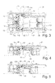
Figure 1 is a lateral view, in section along a longitudinal centre line plane, of a unit according to the invention, with a capsule shown by means of dashed lines at three different moments, respectively a) before insertion into the unit, b) inserted into the unit before the perforation step, c) discharged from the unit; -
Figure 2 is a front view of the unit in section along the line II-II ofFigure 1 ; -
Figures 3 to 8 each show a view from above of the unit according to the invention, in section along a horizontal plane, shown in different steps of processing of the capsule; -
Figures 9, 10 and 11 respectively showfigures 3, 5 and8 on an enlarged scale; -
Figure 12 is a side view of the unit with the actuating lever shown in two different positions. - With reference to the aforesaid figures, a capsule usable in a positioning and extracting unit according to the invention is indicated by C and is constituted by a flared, cup-shaped body C1, which has on the upper edge a flange C2 onto which a sealing film C3 is welded.
- The unit for positioning and extracting single-use capsules comprises an
outer casing 11 in which is defined avertical pipe 12, open at the top for the insertion of a capsule C. Thepipe 12 is configured so as to allow the capsule to slide, by gravity, oriented with its axis C5 substantially orthogonal to the length of the pipe itself. In particular, the cross-section of the pipe is partially of complementary shape to the cross-section of the capsule C to allow guided sliding thereof. - In an intermediate position of the pipe 12 a
dwell zone 13 is defined in which the capsule is processed, as described in more detail hereinafter; the dwell zone is in practice a chamber which intersects thepipe 12 and which extends in a direction transverse to the latter, dividing it substantially into three parts: an upper part in which the opening 12a for the insertion of the capsule C is defined, a central part corresponding to thedwell zone 13, and a lower part in which thedischarge outlet 12b for the capsule C is defined. - At the
dwell zone 13, on opposite sides of thepipe 12, there aresupport shoulders 14 for supporting external parts of the edge of the flange C2 of the capsule, opposed with respect to the axis C5; theshoulders 14 allow the blocking of the capsule as it drops from the upper opening 12a of thepipe 12. When the capsule is resting on theshoulders 14, the direction in which thedwell zone 13 extends coincides with the axis C5 of the capsule itself. - The
pipe 12, in front of theshoulders 14 in the opposite direction to that in which the capsule extends when disposed on the shoulders, has aportion 12c having a width greater than the distance between those shoulders. Theportion 12c extends as far as thedischarge outlet 12b and allows the capsule to drop towards theoutlet 12b, as described in more detail hereinafter. - At one end of the
dwell zone 13 there is asmall plate 15, substantially fixed to thecasing 11, and which has in the centre anozzle 16 for the injection of water coming from the pumping means of the coffee machine with which the unit is associated, which means is not shown in the drawings. At the inlet of thenozzle 16 there is an over-pressurevalve 17 of the spring type, which opens when the pressure of the water coming from the pumping means exceeds the resistance value of the spring. On the surface of theplate 15 which faces thezone 13 there are perforating means for perforating the film C3 of the capsule, such as a plurality of perforating needles 18 (in other embodiments, the tearing of the film may be effected solely by means of the jet of water, thus avoiding the presence of perforating needles). Anannular gasket 19 is disposed inside a correspondingannular recess 20 provided on the surface of theplate 15 on the perimeter of the area occupied by theneedles 18, and its aim is to prevent water leaking laterally during the soaking of the capsule, as will become clearer hereinafter. According to what has been stated previously, theportion 12c of thepipe 12 in which the capsule C drops, and which has a width greater than the distance between theshoulders 14, is defined between theplate 15 and the shoulders themselves. - In the dwell zone 13 a cup-
shaped body 21 facing towards theplate 15 is arranged to slide and has a shape substantially complimentary to the capsule C. An important aspect of the invention is that the cup-shaped body 21 is coaxial with the direction in which the dwell zone extends, or with the axis C5 of the capsule when resting on theshoulders 14. - On the
bottom 21a of the cup-shaped body 21 there are further perforating means for the base C6 of the capsule, such as a plurality of further perforatingneedles 22 emerging from asmall disc 23 secured to thebottom 21a by means of a screw; thedisc 23 is configured so as to define with thebottom 21a anair gap 24, and has a through-hole 23a (shown by way of example inFigure 1 ) which places theair gap 24 in communication with the space in the cup-shaped body which receives the capsule C. - As can be seen in
Figure 1 , on thebottom 21a there are means for conveying the coffee towards the dispensing zone of the machine with which the unit is associated, such as apipe 25 integral with the bottom itself, and thedischarge outlet 25a of which is superposed on afunnel portion 26 integral with thecasing 11 and which ends above the zone on which the coffee-cup is to be arranged (indicated by T inFigure 12 ). - Associated with the cup-
shaped body 21 is ameans 27 which allows translation thereof orthogonal to thepipe 12, from a position outside the pipe to a position behind theplate 15. Such translation permits the coupling of the cup-shaped body 21 to the capsule C and the displacement of the latter into abutment on theplate 15. - As can be seen in
Figure 12 , the translation means 27 is constituted in this embodiment by a kinetic motion means comprising aguide 28 for the cup-shaped body 21, defined on thecasing 11, parallel to the direction in which the dwell zone extends, a connectingrod 29 pivoted by one end on the sides of the cup-shaped body 21 and by the opposite end on a rocker-arm 30 which is itself pivoted on thecasing 11. Alever 31 for actuating the kinematic motion means is integral with the rocker-arm 30. - Along the
pipe 12, at theportion 12c in which the capsule drops towards thedischarge outlet 12b, there are locatingmeans 32 for the capsule which prevent the return movement of the latter from theplate 15 onto thesupport shoulders 14. - According to the invention, the locating means 32 yield when urged towards the
plate 15 and are substantially rigid when urged by the flange C2 towards the cup-shaped body 21, such as to allow the passage of the capsule towards theplate 15 and to prevent the passage of the capsule during the return movement of the cup-shaped body 21 towards the position outside thepipe 12 by interference with the flange C2, thus permitting the extraction of the capsule C' from the cup-shaped body 21 and the consequent drop towards the discharge outlet, inasmuch as it is not supported. - The locating
means 32, clearly visible inFigures 9, 10 and 11 , comprise, for example, twogates 33 which are secured to the respective opposed sides of thepipe 12, and which have substantially two positions: a first position in which they extend towards the centre of the dwell zone, where they interfere with the movement of the capsule, and a second position behind the corresponding side of the pipe; said second position does not interfere with the movement of the capsule. Associated with thegates 33 areresilient means 34 which permit their return from the second position to the first position. Preferably, eachgate 33 is hinged to thecasing 11 via apin 35 substantially parallel to the length of thepipe 12, or orthogonal to the direction in which thedwell zone 13 extends and to the axis C5 of the capsule. Theresilient means 34 are constituted by torsion springs wound oncorresponding pins 35, and first ends of which are fixed to thecasing 11 while the second ends thrust against thecorresponding gates 33. When thegates 33 are in the aforesaid first position, they bear on corresponding rotational end stops 36. - The operation of the invention is as follows: the capsule C is inserted into the upper opening 12a of the
pipe 12. The capsule is guided by the complementary shape of the pipe until it comes to rest with the edge of the flange C2 on the shoulders 14 (seeFigures 1 ,3 and9 ). The space occupied by the flange C2 of the capsule at eachshoulder 14 is delimited below by the shoulder itself and on two sides by the correspondinggate 33 and by avertical guide shoulder 37. At this point, by acting on thelever 31, the cup-shapedbody 21 is translated in such a way that the capsule C is inserted into the cup-shaped body (they are coaxial), in particular the perforatingneedles 22 are located against the base of the capsule (seeFig. 4 ). Further rotation of thelever 31 causes the cup-shapedbody 21 to press on the capsule and consequently to push the flange C2 of the capsule against thegates 33; these rotate, allowing the capsule and the cup-shaped body to pass through (seeFigures 5 and10 ). At this point, a further rotatory movement of thelever 31 brings the capsule into abutment on theplate 15 and on thegasket 19, allowing the needles to tear the film (seeFigure 6 ) and the opposed base C6. Owing to the fact that the edge 33a of the gates which faces towards the centre of thedwell zone 13 has a shape substantially complementary to the external circular shape of the cup-shapedbody 21 and that the distance between the twogates 33 is greater than (or at least equal to) the outside diameter of the cup-shapedbody 21, thegates 33 do not interfere with the latter. For this reason, once the flange has passed through thegates 33, the latter return from the second position into the first position by virtue of the thrust imposed by the torsion springs 34. - Via the
nozzle 16, hot water is then injected which soaks the capsule torn by the needles, passing through it, and thus mixing with the coffee powder; the flow of beverage obtained is conveyed as far as the zone in which it is poured into the coffee-cup T. - When this operation is completed, a contrary rotatory movement of the
lever 31 makes it possible to reverse the motion of the cup-shapedbody 21 with the capsule. When the flange C2 of the capsule meets thegates 33, the latter, which cannot rotate since they are prevented by theend stop 36, block the capsule while the cup-shapedbody 21 continues to be translated (seeFigures 8 and11 ). The result is the extraction of the capsule from the cup-shaped body. Once the cup-shapedbody 21 has returned to the initial position outside thepipe 12, the capsule is no longer supported by anything and therefore drops along thedrop portion 12c of the pipe, as far as thedischarge outlet 12b. - It is clear that other kinds of locating means that yield in only one direction are possible. For example, other locating means (not shown in the drawings) may be constituted by two small cylinders, emerging from respective guide seats provided in respective sides of the
pipe 12, interfering with the movement space of the capsule; between the bottom of the seats and the cylinders, springs are arranged which oppose the re-entry movement of the cylinders into the seats; the protruding ends of the cylinders are chamfered on the side encountered by the capsule in the movement in which it approaches the plate; in this way the capsule, encountering the chamfered sides, imparts a re-entry thrust to the cylinders, while in its motion in the opposite direction, the capsule encounters the unchamfered sides of the cylinders, being blocked. - Furthermore, another embodiment may provide, as locating means, resiliently flexible thin plates (of suitable rigidity) protruding in a cantilevered manner from respective sides of the pipe in an inclined manner, with the free ends facing substantially towards the plate, thus permitting the passage of the capsule towards the latter but not the opposite movement.
- In practice, it has been found that the invention achieves the aims proposed. In fact, by making the cup-shaped body coaxial with the capsule when resting on the shoulders, the deformation of the capsule is avoided. This results in a reduction in the occurrence of blocking of the capsule in the unit and of the occurrence of undesired breakage of the capsule. In order to allow the coaxial arrangement, it was necessary to use locating means for the capsule in the step of extraction from the cup-shaped body which would yield in the direction in which the capsule approaches the plate for perforation and injection, and which would be rigid in the opposite direction in order to allow the extraction of the capsule from the cup-shaped body.
- The unit thus designed is capable of numerous modifications and variants, all coming within the scope of the same inventive concept; moreover, all the details may be substituted by other technically equivalent elements, without thereby departing from the scope of protection of the invention itself.
- In practice, the materials used, provided they are compatible with the specific use, and also the dimensions, may be any whatever, according to the requirements and the state of the art.
- Wherever the characteristics and techniques mentioned in any claim are followed by reference signs, these have been appended, by way of example, solely in order to increase the intelligibility of the claims and consequently have no limiting effect on the interpretation of each element which they identify.
Claims (6)
- A unit for positioning and extracting single-use capsules for coffee machines, comprising- a pipe (12), open at the top, for the insertion of a dedicated capsule (C), said pipe (12) being configured so as to allow said capsule (C) to slide, by gravity, oriented with its axis (C5) substantially transverse to the length of the pipe (12) itself;- a dwell zone (13) for the capsule (C), defined in an intermediate position of said pipe (12) and extending in a direction transverse to said pipe (12), at said zone (13), on opposite sides of said pipe (12), support shoulders (14) being provided for supporting external parts (C2) of the capsule (C), opposed with respect to the axis (C5) of the capsule (C) itself;- a small plate (15) disposed at an end of said dwell zone (13) and equipped with at least one nozzle (16) for the injection of water coming from the pumping means of the coffee machine with which the unit is associated,- a cup-shaped body (21) arranged so as to slide in said dwell zone (13) and facing towards said plate (15), translation means (27) being provided for translating said cup-shaped body (21) transversely to said pipe (12) from a position outside the pipe (12) itself to a position behind said plate (15), and suitable for permitting during translation the coupling of the cup-shaped body (21) to the capsule (C) and the displacement of the latter into abutment on said plate (15), conveying means (25) being provided on the bottom (21a) of said cup-shaped body (21) for conveying the coffee towards the dispensing zone of the machine with which the unit is associated and means (22) for breaking the corresponding base (C6) of the capsule (C),- locating means (32) for the capsule (C) which are disposed along said pipe (12) at a portion (12c) of said pipe (12) having a width greater than the distance between the shoulders (14) themselves, defined between said shoulders (14) and said plate (15) and suitable for allowing the capsule (C) to drop downwards, said locating means being suitable for preventing the return movement of the capsule (C) onto said support shoulders (14),characterized in that said cup-shaped body (21) is coaxial with the axis (C5) of said dedicated capsule (C) when the capsule (C) is resting on said shoulders (14), and in that said locating means (32) for the capsule yield when urged towards said plate (15) and are substantially rigid when urged in the opposite direction.
- A unit according to claim 1, characterized in that said locating means (32) comprise two gates (33), secured to the respective opposed sides of said pipe (12) at said drop portion (12c) for the capsule (C), said two gates occupying substantially two positions: a first position in which they extend towards the centre of said dwell zone (13), interfering with the space that can be occupied by the capsule (C), and a second position behind the corresponding side of the pipe (12), not interfering with the movement of the capsule (C), resilient means (34) being provided which oppose the movement of said gates (33) from said first position to said second position.
- A unit according to claim 2, characterized in that each said gate (33) is hinged to the casing (11) of the unit by means of a pin (35) substantially parallel to the length of said pipe (12), or orthogonal to the direction in which the dwell zone (13) extends and to the axis (C5) of the capsule (C), said resilient means (34) being constituted by torsion springs wound on the corresponding pins (35), and first ends of which are fixed to the casing (11) while the second ends thrust against the corresponding gates (33), or vice versa, when the gates (33) are in the aforesaid first position, bearing on corresponding rotational end stops (36).
- A unit according to claim 3, characterized in that the edge (33a) of said gates (33) which faces towards the centre of the dwell zone (13) has a shape substantially complementary to the circular external shape of the cup-shaped body (21).
- A unit according to claim 4, characterized in that the distance between said two gates (33) is greater than the outside diameter of said cup-shaped body (21).
- A unit according to one or more of claims 2 to 5, characterized in that the space that can be occupied by the corresponding part (C2) of capsule (C) at one said shoulder (14) is delimited below by the shoulder itself and on two sides by the corresponding gate (33) and by a vertical guide shoulder (37).
Applications Claiming Priority (2)
| Application Number | Priority Date | Filing Date | Title |
|---|---|---|---|
| IT000120A ITFI20070120A1 (en) | 2007-05-23 | 2007-05-23 | POSITIONING AND EXTRACTION GROUP OF DISPOSABLE PODS FOR COFFEE MACHINES |
| EP08763093A EP2150158A2 (en) | 2007-05-23 | 2008-05-23 | A positioning and extraction assembly for single-use capsules in coffee-making machines |
Related Parent Applications (1)
| Application Number | Title | Priority Date | Filing Date |
|---|---|---|---|
| EP08763093.5 Division | 2008-05-23 |
Publications (2)
| Publication Number | Publication Date |
|---|---|
| EP2425753A1 true EP2425753A1 (en) | 2012-03-07 |
| EP2425753B1 EP2425753B1 (en) | 2013-07-24 |
Family
ID=39941844
Family Applications (2)
| Application Number | Title | Priority Date | Filing Date |
|---|---|---|---|
| EP08763093A Withdrawn EP2150158A2 (en) | 2007-05-23 | 2008-05-23 | A positioning and extraction assembly for single-use capsules in coffee-making machines |
| EP11190308.4A Not-in-force EP2425753B1 (en) | 2007-05-23 | 2008-05-23 | A positioning and extraction assembly for single-use capsules in coffee-making machines |
Family Applications Before (1)
| Application Number | Title | Priority Date | Filing Date |
|---|---|---|---|
| EP08763093A Withdrawn EP2150158A2 (en) | 2007-05-23 | 2008-05-23 | A positioning and extraction assembly for single-use capsules in coffee-making machines |
Country Status (4)
| Country | Link |
|---|---|
| EP (2) | EP2150158A2 (en) |
| AT (1) | ATE537741T1 (en) |
| IT (1) | ITFI20070120A1 (en) |
| WO (1) | WO2008142663A2 (en) |
Cited By (6)
| Publication number | Priority date | Publication date | Assignee | Title |
|---|---|---|---|---|
| CN103747713A (en) * | 2011-06-09 | 2014-04-23 | 路易吉·拉瓦扎股份公司 | Delivery assembly for machines for preparing liquid products via cartridges |
| CN103989407A (en) * | 2014-05-09 | 2014-08-20 | 宁波全景电器技术有限公司 | Bag feeding and bag taking-off mechanism of beverage making device |
| CN104684443A (en) * | 2012-07-26 | 2015-06-03 | 路易吉·拉瓦扎股份公司 | Dispensing assembly for machines for the preparation of beverages using capsules |
| CN105520632A (en) * | 2015-12-31 | 2016-04-27 | 广东新宝电器股份有限公司 | Capsule coffee machine |
| US11503941B2 (en) | 2017-10-19 | 2022-11-22 | Sgl Italia S.R.L. Con Unico Socio | Brewing device for producing a beverage |
| US11877688B2 (en) | 2017-10-19 | 2024-01-23 | Sgl Italia S.R.L. Con Unico Socio | Brewing device for producing a beverage |
Families Citing this family (15)
| Publication number | Priority date | Publication date | Assignee | Title |
|---|---|---|---|---|
| CN201356446Y (en) * | 2008-12-30 | 2009-12-09 | 薛胜利 | Novel capsule-type coffee maker |
| CN101897544B (en) | 2010-03-31 | 2012-02-15 | 宁波西文电器有限公司 | Coffee machine capable of making coffee package fallen off automatically |
| PL2374383T3 (en) * | 2010-04-07 | 2013-04-30 | Nestec Sa | Extraction system for the production of a beverage using a capsule |
| IT1399732B1 (en) | 2010-05-04 | 2013-05-03 | Mac Design S R L | POSITIONING GROUP AND EXTRACTION OF PODS DISPOSABLE IN COFFEE MACHINES |
| EP2505109A1 (en) * | 2011-03-30 | 2012-10-03 | Celaya, Emparanza Y Galdos Internacional, S.A. | Coffee maker with trolley |
| WO2013079811A1 (en) * | 2011-11-30 | 2013-06-06 | Alain Frydman | Capsule with improved guidance for preparing beverages by extraction |
| ITTO20120304A1 (en) * | 2012-04-06 | 2013-10-07 | Lavazza Luigi Spa | POSITIONING AND EXTRACTION GROUP FOR A MACHINE FOR THE PREPARATION OF A BEVERAGE WITH THE USE OF CAPSULES |
| CN102743107B (en) * | 2012-07-19 | 2015-05-06 | 宁波圣莱达电器股份有限公司 | Brewing device of coffee maker |
| DE102015121029B4 (en) * | 2015-12-03 | 2018-10-31 | Eugster/Frismag Ag | Beverage preparation device, system and operating method |
| CN113163971B (en) * | 2018-10-30 | 2023-03-24 | 埃沃咖股份公司 | Device for restoring the shape of a beverage preparation capsule |
| IT201900012396A1 (en) | 2019-07-19 | 2021-01-19 | Lavazza Luigi Spa | CONTAINER, SYSTEM AND METHOD FOR THE PREPARATION OF FLUID FOOD PRODUCTS |
| IT201900012390A1 (en) | 2019-07-19 | 2021-01-19 | Lavazza Luigi Spa | MACHINE, SYSTEM AND METHOD FOR THE PREPARATION OF FLUID FOOD PRODUCTS |
| IT201900012381A1 (en) | 2019-07-19 | 2021-01-19 | Lavazza Luigi Spa | SYSTEM, MACHINE AND CONTAINER FOR THE PREPARATION OF FLUID FOOD PRODUCTS |
| AU2019464148A1 (en) * | 2019-08-30 | 2022-04-14 | 77 Vision Way Ltd | Device for distributing mineralized water and associated method |
| CN111528689B (en) * | 2020-05-22 | 2024-10-29 | 广东亿龙电器科技有限公司 | Brewing device |
Citations (4)
| Publication number | Priority date | Publication date | Assignee | Title |
|---|---|---|---|---|
| WO2005058111A1 (en) * | 2003-12-11 | 2005-06-30 | Termozeta S.P.A. | Espresso coffee machine |
| EP1721553A1 (en) * | 2005-05-12 | 2006-11-15 | Perfect Steam Appliances Ltd. | Infusion assembly for beverage preparing machine |
| EP1757212A2 (en) * | 2003-07-10 | 2007-02-28 | Nestec S.A. | Device for extracting a capsule |
| WO2008046740A1 (en) * | 2006-10-17 | 2008-04-24 | Samar Technologies Ltd. | Assembly comprising an appliance and a disposable capsule for producing a brewed drink, and capsule for such an assembly |
-
2007
- 2007-05-23 IT IT000120A patent/ITFI20070120A1/en unknown
-
2008
- 2008-05-23 EP EP08763093A patent/EP2150158A2/en not_active Withdrawn
- 2008-05-23 WO PCT/IB2008/052044 patent/WO2008142663A2/en not_active Ceased
- 2008-05-23 AT AT08763093T patent/ATE537741T1/en active
- 2008-05-23 EP EP11190308.4A patent/EP2425753B1/en not_active Not-in-force
Patent Citations (4)
| Publication number | Priority date | Publication date | Assignee | Title |
|---|---|---|---|---|
| EP1757212A2 (en) * | 2003-07-10 | 2007-02-28 | Nestec S.A. | Device for extracting a capsule |
| WO2005058111A1 (en) * | 2003-12-11 | 2005-06-30 | Termozeta S.P.A. | Espresso coffee machine |
| EP1721553A1 (en) * | 2005-05-12 | 2006-11-15 | Perfect Steam Appliances Ltd. | Infusion assembly for beverage preparing machine |
| WO2008046740A1 (en) * | 2006-10-17 | 2008-04-24 | Samar Technologies Ltd. | Assembly comprising an appliance and a disposable capsule for producing a brewed drink, and capsule for such an assembly |
Cited By (9)
| Publication number | Priority date | Publication date | Assignee | Title |
|---|---|---|---|---|
| CN103747713A (en) * | 2011-06-09 | 2014-04-23 | 路易吉·拉瓦扎股份公司 | Delivery assembly for machines for preparing liquid products via cartridges |
| CN103747713B (en) * | 2011-06-09 | 2016-09-14 | 路易吉·拉瓦扎股份公司 | For preparing the conveying assembly of the machine of fluid product via box |
| CN104684443A (en) * | 2012-07-26 | 2015-06-03 | 路易吉·拉瓦扎股份公司 | Dispensing assembly for machines for the preparation of beverages using capsules |
| CN104684443B (en) * | 2012-07-26 | 2018-02-06 | 路易吉·拉瓦扎股份公司 | Dispensing assembly for machines for preparing beverages using capsules |
| CN103989407A (en) * | 2014-05-09 | 2014-08-20 | 宁波全景电器技术有限公司 | Bag feeding and bag taking-off mechanism of beverage making device |
| CN105520632A (en) * | 2015-12-31 | 2016-04-27 | 广东新宝电器股份有限公司 | Capsule coffee machine |
| CN105520632B (en) * | 2015-12-31 | 2018-06-12 | 广东新宝电器股份有限公司 | Capsule coffee machine |
| US11503941B2 (en) | 2017-10-19 | 2022-11-22 | Sgl Italia S.R.L. Con Unico Socio | Brewing device for producing a beverage |
| US11877688B2 (en) | 2017-10-19 | 2024-01-23 | Sgl Italia S.R.L. Con Unico Socio | Brewing device for producing a beverage |
Also Published As
| Publication number | Publication date |
|---|---|
| EP2425753B1 (en) | 2013-07-24 |
| ITFI20070120A1 (en) | 2008-11-24 |
| EP2150158A2 (en) | 2010-02-10 |
| WO2008142663A2 (en) | 2008-11-27 |
| WO2008142663A3 (en) | 2009-02-05 |
| ATE537741T1 (en) | 2012-01-15 |
Similar Documents
| Publication | Publication Date | Title |
|---|---|---|
| EP2425753A1 (en) | A positioning and extraction assembly for single-use capsules in coffee-making machines | |
| AU2021204827B2 (en) | A capsule, a system for preparing a potable beverage from such a capsule and use of such a capsule in a beverage preparation device | |
| RU2431441C2 (en) | Capsule with external sealing material, which is pressurised by fluid medium | |
| EP2833766B1 (en) | Brewing assembly for brewed beverage vending machines | |
| US9661948B2 (en) | Device for preparing a drink | |
| AU2008212121B2 (en) | Infusion device to prepare beverages from single-serving capsules with capsule centering device | |
| AU2014331506B2 (en) | Brewing module | |
| US10207860B2 (en) | Cartridge for preparing a beverage | |
| AU2011229234B2 (en) | A beverage machine using ingredient capsules | |
| JP6082098B2 (en) | Positioning and extraction assembly for a machine for dispensing beverages using capsules | |
| EP2218367B1 (en) | Perforation device for capsules and machine for preparing beverages incorporating said device | |
| EP2452893B1 (en) | Capsule for containing a preparation for a hot drink | |
| KR20230153523A (en) | A capsule, a system for preparing a potable beverage from such a capsule and use of such a capsule in a beverage preparation device | |
| EP2656755B1 (en) | Infusion group | |
| EP3032988A1 (en) | Capsule multi-piercer with assembly means | |
| EP3199071B1 (en) | System for preparing a liquid beverage from a capsule | |
| US12245716B2 (en) | Beverage extraction unit with movable outflow obstructor | |
| EP2301395B1 (en) | Device for preparing infused beverages | |
| EP3134335B1 (en) | A capsule, a system for preparing a potable beverage from such a capsule and use of such a capsule in a beverage preparation device | |
| KR20140126793A (en) | Beverage discharging structure of beverge capsule | |
| KR200489725Y1 (en) | Food discharge device | |
| EP3199072B1 (en) | A system for preparing a liquid beverage from a capsule, a capsule configured to be used in a system | |
| CN114599257A (en) | Drinking container with enhanced flow conditioning unit, system and method utilizing same | |
| KR20230111391A (en) | Capsule holder and apparatus for extracting beverage from capsule | |
| HK1170397A1 (en) | System, apparatus and method for preparing a beverage |
Legal Events
| Date | Code | Title | Description |
|---|---|---|---|
| AC | Divisional application: reference to earlier application |
Ref document number: 2150158 Country of ref document: EP Kind code of ref document: P |
|
| AK | Designated contracting states |
Kind code of ref document: A1 Designated state(s): AT BE BG CH CY CZ DE DK EE ES FI FR GB GR HR HU IE IS IT LI LT LU LV MC MT NL NO PL PT RO SE SI SK TR |
|
| PUAI | Public reference made under article 153(3) epc to a published international application that has entered the european phase |
Free format text: ORIGINAL CODE: 0009012 |
|
| 17P | Request for examination filed |
Effective date: 20120905 |
|
| GRAP | Despatch of communication of intention to grant a patent |
Free format text: ORIGINAL CODE: EPIDOSNIGR1 |
|
| GRAS | Grant fee paid |
Free format text: ORIGINAL CODE: EPIDOSNIGR3 |
|
| GRAA | (expected) grant |
Free format text: ORIGINAL CODE: 0009210 |
|
| AC | Divisional application: reference to earlier application |
Ref document number: 2150158 Country of ref document: EP Kind code of ref document: P |
|
| AK | Designated contracting states |
Kind code of ref document: B1 Designated state(s): AT BE BG CH CY CZ DE DK EE ES FI FR GB GR HR HU IE IS IT LI LT LU LV MC MT NL NO PL PT RO SE SI SK TR |
|
| REG | Reference to a national code |
Ref country code: GB Ref legal event code: FG4D |
|
| REG | Reference to a national code |
Ref country code: CH Ref legal event code: EP |
|
| REG | Reference to a national code |
Ref country code: AT Ref legal event code: REF Ref document number: 622897 Country of ref document: AT Kind code of ref document: T Effective date: 20130815 |
|
| REG | Reference to a national code |
Ref country code: IE Ref legal event code: FG4D |
|
| REG | Reference to a national code |
Ref country code: DE Ref legal event code: R096 Ref document number: 602008026333 Country of ref document: DE Effective date: 20130919 |
|
| REG | Reference to a national code |
Ref country code: AT Ref legal event code: MK05 Ref document number: 622897 Country of ref document: AT Kind code of ref document: T Effective date: 20130724 |
|
| REG | Reference to a national code |
Ref country code: NL Ref legal event code: VDEP Effective date: 20130724 |
|
| REG | Reference to a national code |
Ref country code: LT Ref legal event code: MG4D |
|
| PG25 | Lapsed in a contracting state [announced via postgrant information from national office to epo] |
Ref country code: BE Free format text: LAPSE BECAUSE OF FAILURE TO SUBMIT A TRANSLATION OF THE DESCRIPTION OR TO PAY THE FEE WITHIN THE PRESCRIBED TIME-LIMIT Effective date: 20130724 Ref country code: HR Free format text: LAPSE BECAUSE OF FAILURE TO SUBMIT A TRANSLATION OF THE DESCRIPTION OR TO PAY THE FEE WITHIN THE PRESCRIBED TIME-LIMIT Effective date: 20130724 Ref country code: NO Free format text: LAPSE BECAUSE OF FAILURE TO SUBMIT A TRANSLATION OF THE DESCRIPTION OR TO PAY THE FEE WITHIN THE PRESCRIBED TIME-LIMIT Effective date: 20131024 Ref country code: IS Free format text: LAPSE BECAUSE OF FAILURE TO SUBMIT A TRANSLATION OF THE DESCRIPTION OR TO PAY THE FEE WITHIN THE PRESCRIBED TIME-LIMIT Effective date: 20131124 Ref country code: AT Free format text: LAPSE BECAUSE OF FAILURE TO SUBMIT A TRANSLATION OF THE DESCRIPTION OR TO PAY THE FEE WITHIN THE PRESCRIBED TIME-LIMIT Effective date: 20130724 Ref country code: CY Free format text: LAPSE BECAUSE OF FAILURE TO SUBMIT A TRANSLATION OF THE DESCRIPTION OR TO PAY THE FEE WITHIN THE PRESCRIBED TIME-LIMIT Effective date: 20130814 Ref country code: SE Free format text: LAPSE BECAUSE OF FAILURE TO SUBMIT A TRANSLATION OF THE DESCRIPTION OR TO PAY THE FEE WITHIN THE PRESCRIBED TIME-LIMIT Effective date: 20130724 Ref country code: LT Free format text: LAPSE BECAUSE OF FAILURE TO SUBMIT A TRANSLATION OF THE DESCRIPTION OR TO PAY THE FEE WITHIN THE PRESCRIBED TIME-LIMIT Effective date: 20130724 Ref country code: PT Free format text: LAPSE BECAUSE OF FAILURE TO SUBMIT A TRANSLATION OF THE DESCRIPTION OR TO PAY THE FEE WITHIN THE PRESCRIBED TIME-LIMIT Effective date: 20131125 |
|
| PG25 | Lapsed in a contracting state [announced via postgrant information from national office to epo] |
Ref country code: GR Free format text: LAPSE BECAUSE OF FAILURE TO SUBMIT A TRANSLATION OF THE DESCRIPTION OR TO PAY THE FEE WITHIN THE PRESCRIBED TIME-LIMIT Effective date: 20131025 Ref country code: NL Free format text: LAPSE BECAUSE OF FAILURE TO SUBMIT A TRANSLATION OF THE DESCRIPTION OR TO PAY THE FEE WITHIN THE PRESCRIBED TIME-LIMIT Effective date: 20130724 Ref country code: SI Free format text: LAPSE BECAUSE OF FAILURE TO SUBMIT A TRANSLATION OF THE DESCRIPTION OR TO PAY THE FEE WITHIN THE PRESCRIBED TIME-LIMIT Effective date: 20130724 Ref country code: LV Free format text: LAPSE BECAUSE OF FAILURE TO SUBMIT A TRANSLATION OF THE DESCRIPTION OR TO PAY THE FEE WITHIN THE PRESCRIBED TIME-LIMIT Effective date: 20130724 Ref country code: FI Free format text: LAPSE BECAUSE OF FAILURE TO SUBMIT A TRANSLATION OF THE DESCRIPTION OR TO PAY THE FEE WITHIN THE PRESCRIBED TIME-LIMIT Effective date: 20130724 Ref country code: PL Free format text: LAPSE BECAUSE OF FAILURE TO SUBMIT A TRANSLATION OF THE DESCRIPTION OR TO PAY THE FEE WITHIN THE PRESCRIBED TIME-LIMIT Effective date: 20130724 |
|
| PG25 | Lapsed in a contracting state [announced via postgrant information from national office to epo] |
Ref country code: CY Free format text: LAPSE BECAUSE OF FAILURE TO SUBMIT A TRANSLATION OF THE DESCRIPTION OR TO PAY THE FEE WITHIN THE PRESCRIBED TIME-LIMIT Effective date: 20130724 |
|
| PG25 | Lapsed in a contracting state [announced via postgrant information from national office to epo] |
Ref country code: EE Free format text: LAPSE BECAUSE OF FAILURE TO SUBMIT A TRANSLATION OF THE DESCRIPTION OR TO PAY THE FEE WITHIN THE PRESCRIBED TIME-LIMIT Effective date: 20130724 Ref country code: CZ Free format text: LAPSE BECAUSE OF FAILURE TO SUBMIT A TRANSLATION OF THE DESCRIPTION OR TO PAY THE FEE WITHIN THE PRESCRIBED TIME-LIMIT Effective date: 20130724 Ref country code: RO Free format text: LAPSE BECAUSE OF FAILURE TO SUBMIT A TRANSLATION OF THE DESCRIPTION OR TO PAY THE FEE WITHIN THE PRESCRIBED TIME-LIMIT Effective date: 20130724 Ref country code: SK Free format text: LAPSE BECAUSE OF FAILURE TO SUBMIT A TRANSLATION OF THE DESCRIPTION OR TO PAY THE FEE WITHIN THE PRESCRIBED TIME-LIMIT Effective date: 20130724 Ref country code: DK Free format text: LAPSE BECAUSE OF FAILURE TO SUBMIT A TRANSLATION OF THE DESCRIPTION OR TO PAY THE FEE WITHIN THE PRESCRIBED TIME-LIMIT Effective date: 20130724 |
|
| PG25 | Lapsed in a contracting state [announced via postgrant information from national office to epo] |
Ref country code: ES Free format text: LAPSE BECAUSE OF FAILURE TO SUBMIT A TRANSLATION OF THE DESCRIPTION OR TO PAY THE FEE WITHIN THE PRESCRIBED TIME-LIMIT Effective date: 20130724 |
|
| PLBE | No opposition filed within time limit |
Free format text: ORIGINAL CODE: 0009261 |
|
| STAA | Information on the status of an ep patent application or granted ep patent |
Free format text: STATUS: NO OPPOSITION FILED WITHIN TIME LIMIT |
|
| 26N | No opposition filed |
Effective date: 20140425 |
|
| REG | Reference to a national code |
Ref country code: DE Ref legal event code: R097 Ref document number: 602008026333 Country of ref document: DE Effective date: 20140425 |
|
| PG25 | Lapsed in a contracting state [announced via postgrant information from national office to epo] |
Ref country code: LU Free format text: LAPSE BECAUSE OF FAILURE TO SUBMIT A TRANSLATION OF THE DESCRIPTION OR TO PAY THE FEE WITHIN THE PRESCRIBED TIME-LIMIT Effective date: 20140523 |
|
| REG | Reference to a national code |
Ref country code: CH Ref legal event code: PL |
|
| GBPC | Gb: european patent ceased through non-payment of renewal fee |
Effective date: 20140523 |
|
| PG25 | Lapsed in a contracting state [announced via postgrant information from national office to epo] |
Ref country code: CH Free format text: LAPSE BECAUSE OF NON-PAYMENT OF DUE FEES Effective date: 20140531 Ref country code: MC Free format text: LAPSE BECAUSE OF FAILURE TO SUBMIT A TRANSLATION OF THE DESCRIPTION OR TO PAY THE FEE WITHIN THE PRESCRIBED TIME-LIMIT Effective date: 20130724 Ref country code: LI Free format text: LAPSE BECAUSE OF NON-PAYMENT OF DUE FEES Effective date: 20140531 |
|
| REG | Reference to a national code |
Ref country code: IE Ref legal event code: MM4A |
|
| PG25 | Lapsed in a contracting state [announced via postgrant information from national office to epo] |
Ref country code: IE Free format text: LAPSE BECAUSE OF NON-PAYMENT OF DUE FEES Effective date: 20140523 |
|
| PG25 | Lapsed in a contracting state [announced via postgrant information from national office to epo] |
Ref country code: GB Free format text: LAPSE BECAUSE OF NON-PAYMENT OF DUE FEES Effective date: 20140523 |
|
| PG25 | Lapsed in a contracting state [announced via postgrant information from national office to epo] |
Ref country code: MT Free format text: LAPSE BECAUSE OF FAILURE TO SUBMIT A TRANSLATION OF THE DESCRIPTION OR TO PAY THE FEE WITHIN THE PRESCRIBED TIME-LIMIT Effective date: 20130724 |
|
| REG | Reference to a national code |
Ref country code: FR Ref legal event code: PLFP Year of fee payment: 9 |
|
| PG25 | Lapsed in a contracting state [announced via postgrant information from national office to epo] |
Ref country code: BG Free format text: LAPSE BECAUSE OF FAILURE TO SUBMIT A TRANSLATION OF THE DESCRIPTION OR TO PAY THE FEE WITHIN THE PRESCRIBED TIME-LIMIT Effective date: 20130724 |
|
| PG25 | Lapsed in a contracting state [announced via postgrant information from national office to epo] |
Ref country code: HU Free format text: LAPSE BECAUSE OF FAILURE TO SUBMIT A TRANSLATION OF THE DESCRIPTION OR TO PAY THE FEE WITHIN THE PRESCRIBED TIME-LIMIT; INVALID AB INITIO Effective date: 20080523 Ref country code: TR Free format text: LAPSE BECAUSE OF FAILURE TO SUBMIT A TRANSLATION OF THE DESCRIPTION OR TO PAY THE FEE WITHIN THE PRESCRIBED TIME-LIMIT Effective date: 20130724 |
|
| REG | Reference to a national code |
Ref country code: FR Ref legal event code: PLFP Year of fee payment: 10 |
|
| PGFP | Annual fee paid to national office [announced via postgrant information from national office to epo] |
Ref country code: FR Payment date: 20170530 Year of fee payment: 10 |
|
| PGFP | Annual fee paid to national office [announced via postgrant information from national office to epo] |
Ref country code: IT Payment date: 20170522 Year of fee payment: 10 |
|
| PGFP | Annual fee paid to national office [announced via postgrant information from national office to epo] |
Ref country code: DE Payment date: 20170731 Year of fee payment: 10 |
|
| REG | Reference to a national code |
Ref country code: DE Ref legal event code: R119 Ref document number: 602008026333 Country of ref document: DE |
|
| PG25 | Lapsed in a contracting state [announced via postgrant information from national office to epo] |
Ref country code: DE Free format text: LAPSE BECAUSE OF NON-PAYMENT OF DUE FEES Effective date: 20181201 Ref country code: FR Free format text: LAPSE BECAUSE OF NON-PAYMENT OF DUE FEES Effective date: 20180531 Ref country code: IT Free format text: LAPSE BECAUSE OF NON-PAYMENT OF DUE FEES Effective date: 20180523 |