EP2425877A1 - Equipement de prévention contre les incendies - Google Patents
Equipement de prévention contre les incendies Download PDFInfo
- Publication number
- EP2425877A1 EP2425877A1 EP09843971A EP09843971A EP2425877A1 EP 2425877 A1 EP2425877 A1 EP 2425877A1 EP 09843971 A EP09843971 A EP 09843971A EP 09843971 A EP09843971 A EP 09843971A EP 2425877 A1 EP2425877 A1 EP 2425877A1
- Authority
- EP
- European Patent Office
- Prior art keywords
- water
- particle
- fire
- jetting
- particles
- Prior art date
- Legal status (The legal status is an assumption and is not a legal conclusion. Google has not performed a legal analysis and makes no representation as to the accuracy of the status listed.)
- Granted
Links
Images


Classifications
-
- A—HUMAN NECESSITIES
- A62—LIFE-SAVING; FIRE-FIGHTING
- A62C—FIRE-FIGHTING
- A62C31/00—Delivery of fire-extinguishing material
- A62C31/02—Nozzles specially adapted for fire-extinguishing
-
- A—HUMAN NECESSITIES
- A62—LIFE-SAVING; FIRE-FIGHTING
- A62C—FIRE-FIGHTING
- A62C35/00—Permanently-installed equipment
-
- A—HUMAN NECESSITIES
- A62—LIFE-SAVING; FIRE-FIGHTING
- A62C—FIRE-FIGHTING
- A62C99/00—Subject matter not provided for in other groups of this subclass
- A62C99/0009—Methods of extinguishing or preventing the spread of fire by cooling down or suffocating the flames
- A62C99/0072—Methods of extinguishing or preventing the spread of fire by cooling down or suffocating the flames using sprayed or atomised water
Definitions
- the present invention relates to a fire prevention equipment for electrifying and spraying water-based fire-extinguishing agent particles containing water, seawater, and/or a fire-extinguishing chemical agent from a head.
- the water-based fire prevention equipment of this type includes sprinkler fire extinguishment, water atomization fire-extinguishing equipment, water mist fire-extinguishing equipment, and so on.
- the water mist fire-extinguishing equipment downsizes water particles to 20 to 200 ⁇ m or fraction of that of the sprinkler equipment or water atomization equipment and discharges the water particles to space, thereby expecting a fire extinguishing effect with a small water volume by a cooling effect and the oxygen supply inhibiting effect of evaporated water.
- the sprinkler fire-extinguishing equipment, water atomization fire-extinguishing equipment, or water mist fire-extinguishing equipment using water as a fire extinguishing agent is re-evaluated since the equipment uses water friendly to environments and human bodies as the fire extinguishing agent compared with gas-based fire-extinguishing agents of, for example, carbon dioxide and halon.
- the water mist fire-extinguishing equipment which is assumed to cause small wet damage, is intended to obtain a cooling effect and the effect of inhibiting oxygen supply by evaporated water by filling space with comparatively small water particles; however, the fire extinguishing ability thereof is not so high in reality.
- a fire prevention equipment capable of enhancing the wetting effect with respect to burning objects by the Coulomb force acting on fire-extinguishing-agent particles to obtain a high fire extinguishing effect by electrifying the fire-extinguishing-agent particles sprayed from a head in case of fire and further capable of enhancing the effect of collecting the smoke generated by the fire by the Coulomb force of the fire-extinguishing-agent particles to enhance the smoke removing effect.
- the water particles are discharged from the head at an initial velocity of about 23 m/s; however, for example in the direction immediately lateral thereto, the particles stall at a flying distance of about 1 m or less due to air resistance.
- a fire prevention equipment capable of ensuring a wide protection range by extending the flying distances of the particles of a fire extinguishing agent electrified and sprayed from a head.
- the present invention is a fire prevention equipment having:
- the electrification spray head discharges the water-based fire-extinguishing agent including the mixture of the comparatively-small particle size and the comparatively-large particle size included in the range of 30 ⁇ m to 2000 ⁇ m.
- the electrification spray head has a small-particle-size head unit discharging the water-based fire-extinguishing agent having an average particle size within the range of 30 ⁇ m to 200 ⁇ m, and a large-particle-size head unit discharging the water-based fire-extinguishing agent having an average particle size within the range of 200 ⁇ to 2000 ⁇ m.
- the small-particle head unit and the large-particle head unit are laterally arranged to be adjacent to each other; the small-particle-size head unit has:
- the electrification spray head has:
- the electrification spray head has:
- the electrification spray head has:
- the electrification spray head positively or negatively electrifies the particles of the fire-extinguishing agent included in the predetermined particle size range.
- the groups of the water-based electrified fire-extinguishing-agent particles in which the comparatively small particle size and the comparatively large particle size included in the predetermined particle size range such as the range of 30 ⁇ m to 2000 ⁇ m are mixed is discharged from the electrification spray head.
- the group of the fire-extinguishing-agent small-particle-size particles having an average particle size in the range of 30 ⁇ m to 200 ⁇ m wherein a fire extinguishing effect and a smoke removing effect are high can be sprayed over a wide range by the air convection caused by the group of the fire-extinguishing-agent particles having a large average particle size in the range of 200 ⁇ to 2000 ⁇ m wherein the flying distance thereof is long.
- the particles can be easily sprayed over a range of about 4 m even with a comparatively low pressure of about 0.1 Mp, and an air convection along the spray pattern is observed in this spray.
- the group of the small fire-extinguishing-agent particles are placed on and carried by the convection; as a result, the group of the small fire-extinguishing-agent particles can be sprayed over a wide range together with the group of the large fire-extinguishing-agent particles, and the groups of large and small fire-extinguishing-agent particles can be sprayed all over the protection zone by a small number of spray heads.
- the large-particle-size agent is not good at extinguishing the fire continuously burning in small gaps thereafter and extinguishing fire at the part which cannot be seen from the head (blind area).
- the small fire-extinguishing-agent particles have the function of going around, wetting, and extinguishing the gaps and hidden part by the Coulomb force, and high fire extinguishing performance can be obtained by the mutual effects even in arson fire, etc.
- both of the fire-extinguishing-agent small particles and the fire-extinguishing-agent large particles are positively electrified or negatively electrified.
- association mutually between the fire extinguishing agent of the fire-extinguishing-agent small particles and fire-extinguishing-agent large particles can be prevented in the spray space.
- FIG. 1 is an explanatory drawing showing an embodiment of a fire prevention equipment according to the present invention.
- electrification spray heads 10 according to the present embodiment are installed on the ceiling side of protection areas A and B such as computer rooms in a building.
- a pipe 16 is connected to the electrification spray heads 10 via a manual valve (gate valve) 13 from the projecting side of a pump unit 12 installed for a water source 14, which functions as fire extinguishing agent supplying equipment.
- the pipe 16 is branched and then connected to the electrification spray heads 10, which are installed in the protection areas A and B, via pressure regulating valves 30 and automatic open/close valves 32.
- a dedicated fire detector 18, which controls the spraying from the electrification spray heads 10, is installed in each of the protection areas A and B.
- a linked control relaying devices 20 is provided for each of the protection areas A and B, and a manual operation box 22 for controlling the spray from the electrification spray heads 10 by manual operations is further provided for each of them.
- Signal lines from the dedicated fire detector 18 and the manual operation box 22 are connected to each of the linked control relaying devices 20, and a signal line for applying the voltage for electrification drive to the electrification spray head 10 and a signal line for subjecting the automatic open/close valve 32 to open/close control are wired thereto.
- a fire detector 26 of automatic fire alarm equipment is installed in the protection area A and is connected to a detector line from a receiver 28 of the automatic fire alarm equipment.
- the fire detector 26 of the automatic fire alarm equipment is not provided for the protection area B; however, it goes without saying that the detector may be provided in accordance with needs.
- the linked control relaying devices 20 installed to correspond to the protection areas A and B, respectively, are connected to a system monitoring control board 24 by signal lines.
- the receiver 28 of the automatic fire alarm equipment is also connected to the system monitoring control board 24.
- the system monitoring control board 24 is connected to the pump unit 12 by a signal line and controls pump start/stop of the pump unit 12.
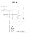
- FIG. 2 is an explanatory drawing focusing on the protection area A of FIG. 1 .
- the electrification spray head 10 is installed in the ceiling side of the protection area A.
- the pipe 16 from the pump unit 12 shown in FIG. 1 is connected to the electrification spray head 10 via the pressure regulating valve 30 and the automatic open/close valve 32.
- a voltage application unit 15 is installed at an upper part of the electrification spray head 10 so as to apply a predetermined voltage to the electrification spray head 10 as is elucidated in later explanation so that the fire extinguishing agent jetted from the electrification spray head 10 can be electrified and sprayed.
- the dedicated fire detector 18 is installed in the ceiling side of the protection area A, and the fire detector 26 of the automatic fire alarm equipment is also connected thereat.
- FIGS. 3A , 3B, and 3C show a first embodiment of the electrification spray head 10 shown in FIG. 1 and FIG. 2 ; wherein FIG. 3A shows a cross section, FIG. 3B shows a plan view viewed from the lower side, and FIG. 3C focuses on an induction electrode.
- the electrification spray head 10 is composed of a small-particle head unit 10A and a large-particle head unit 10B, and both of them are laterally arranged so as to be adjacent to each other.
- the electrification spray head 10 discharges a water-based fire extinguishing agent in which comparatively-small particle sizes and comparatively-large particle sizes included in a predetermined particle-size range are mixed.
- the electrification spray head 10 discharged the water-based fire extinguishing agent in which the comparatively-small particle sizes and the comparatively-large particle sizes included in the range of 30 ⁇ m to 2000 ⁇ m are mixed.
- the small-particle head unit 10A discharges a group of fire extinguishing agent particles having an average particle size within the range of 30 ⁇ m to 200 ⁇ m
- the large-particle head unit 10B discharges a group of fire extinguishing agent particles having an average particle size within the range from 200 ⁇ to 2000 ⁇ m.
- the structure of the small-particle head unit 10A is as described below.
- a head main body 36a is screw-fixed with a distal end of a falling pipe 34a connected to the pipe from the pump unit 12.
- a cylindrical water-side electrode unit 40a is incorporated at the inside of the distal end of the head main body 36a via an insulating member 41a.
- An earth cable 50a is wired from the voltage application unit 15, which is installed at the upper part as shown in FIG. 2 , with respect to the water-side electrode unit 40a and is connected to the water-side electrode unit 40a, which is installed at the inside of the head main body 36a via the insulating member 41a.
- the application voltage of the water-side electrode unit 40 is caused to be 0 volt and lead to the earth side by the connection of the earth cable 50a.
- a small-particle jetting nozzle 38a is provided below the water-side electrode unit 40a.
- the small-particle jetting nozzle 38a is composed of a water-current swirling core 37a, which is provided in the interior of the water-side electrode unit 40a side, and a nozzle head 39b, which is provided in the distal end side.
- the small-particle jetting nozzle 38a receives supply of the water-based fire-extinguishing agent, which is pressurized and supplied from the pump unit 12 of FIG. 1 , from the falling pipe 34a; and the jetting nozzle converts the water-based fire-extinguishing agent into small particles having an average particle size within the range of 30 ⁇ m to 200 ⁇ m and sprays the particles when the water-based fire-extinguishing agent passes through the head main body 36a and is jetted from the nozzle head 39a to the outside.
- the spray pattern sprayed from the small-particle jetting nozzle 38a has the shape of a so-called full cone.
- a cover 42a using an insulating material is fixed by screw-fixing with respect to the small-particle jetting nozzle 38a via a fixing member 43a.
- the cover 42a is an approximately-cylindrical member and incorporates a ring-like induction electrode unit 44a in an open part in the lower side by screw-fixing of a stopper ring 46a.
- the induction electrode unit 44a forms an opening 54a, which allows the jetted particles from the small-particle jetting nozzle 38a to pass therethrough, at the center of a ring-like main body thereof.
- a voltage application cable 48a is wired from the voltage application unit 15 in the upper part shown in FIG. 2 ; and the voltage application cable 48a penetrates through the cover 42a, which is composed of the insulating material, and is connected to the induction electrode unit 44a so that a voltage can be applied thereto.
- the water-side electrode unit 40a and the induction electrode unit 44a used in the electrification spray head 10 of the present embodiment may be, other than metal having electrical conductivity, a resin having electrical conductivity, rubber having electrical conductivity, or a combination of these.
- the voltage application unit 15 shown in FIG. 2 is operated by a control signal, which is from the linked control relaying device 20 shown in FIG. 1 , and applies a DC, AC, or pulsed application voltage of, for example, less than 20 kilovolts to the induction electrode unit 44a while the water-side electrode unit 40 serves as the earth side of 0 volt.
- the jetted small particles are electrified through the jetting process of converting the water-based fire-extinguishing agent to the jetted small particles having the average particle size in the range of 30 ⁇ m to 200 ⁇ m from the small-particle jetting nozzle 38a, and the electrified jetted small particles can be sprayed to the outside.
- the structure of the large-particle head unit 10B is basically the same as that of the small-particle head unit 10A, but is different in the point that a group of fire-extinguishing agent particles having an average particle size in the range of 200 ⁇ to 2000 ⁇ m is discharged.
- a head main body 36b is screw-fixed with a distal end of a falling pipe 34b connected to the pipe from the pump unit 12.
- a pressure limiting orifice 55 is provided inside the head main body 36b.
- the water pressure in a nozzle head 39a is largely reduced through passage through the pressure limiting orifice 55, and jetting of large-particle sizes can be obtained.
- a cylindrical water-side electrode unit 40b is incorporated at the inside of the distal end of the head main body 36b via an insulating member 41b.
- An earth cable 50b is wired from the voltage application unit 15, which is installed at the upper part as shown in FIG. 2 , with respect to the water-side electrode unit 40b and is connected to the water-side electrode unit 40b, which is installed at the inside of the head main body 36b via the insulating member 41b.
- the application voltage of the water-side electrode unit 40b is caused to be 0 volt and lead to the earth side by the connection of the earth cable 50b.
- a large-particle jetting nozzle 38b is provided below the water-side electrode unit 40b.
- the jetting nozzle 38b is composed of a water-current swirling core 37b, which is provided in the interior of the water-side electrode unit 40b side, and a nozzle head 39b, which is provided in the distal end side.
- the large-particle jetting nozzle 38b receives supply of the water-based fire-extinguishing agent, which is pressurized and supplied from the pump unit 12 of FIG. 1 , from the falling pipe 34b; and the jetting nozzle converts the water-based fire-extinguishing agent into large particles having an average particle size within the range of 200 ⁇ m to 2000 ⁇ m and sprays the particles when the water-based fire-extinguishing agent passes through the head main body 36b and is jetted from the nozzle head 39b to the outside via the pressure limiting orifice 55.
- the spray pattern sprayed from the large-particle jetting nozzle 38b has the shape of a so-called full cone.
- a cover 42b using an insulating material is fixed by screw-fixing with respect to the large-particle jetting nozzle 38b via a fixing member 43b.
- the cover 42b is an approximately-cylindrical member and incorporates a ring-like induction electrode unit 44b in an open part in the lower side by screw-fixing of a stopper ring 46b.
- the induction electrode unit 44b forms an opening 54b, which allows the jetted particles from the large-particle jetting nozzle 38b to pass therethrough, at the center of a ring-like main body thereof.
- a voltage application cable 48b is wired from the voltage application unit 15 in the upper part shown in FIG. 2 ; and the voltage application cable 48b penetrates through the cover 42b, which is composed of the insulating material, and is connected to the induction electrode unit 44b so that a voltage can be applied thereto.
- the water-side electrode unit 40a and the induction electrode unit 44b used in the electrification spray head 10 of the present embodiment may be, other than metal having electrical conductivity, a resin having electrical conductivity, rubber having electrical conductivity, or a combination of these.
- the voltage application unit 15 shown in FIG. 2 is operated by a control signal, which is from the linked control relaying device 20 shown in FIG. 1 , and applies a DC, AC, or pulsed application voltage of, for example, less than 20 kilovolts to the ring-like induction electrode unit 44b while the water-side electrode unit 40b serves as the earth side of 0 volt.
- the jetted large particles are electrified through the jetting process of converting the water-based fire-extinguishing agent to the jetted large particles having the average particle size in the range of 200 ⁇ m to 2000 ⁇ m from the large-particle jetting nozzle 38b, and the electrified jetted large particles can be sprayed to the outside.
- the jetting of the group of fire-extinguishing agent small particles by the small-particle head unit 10A and the jetting of the group of fire-extinguishing agent large particles by the large-particle head unit 10B is carried out at the same time to mix them.
- air convection is generated by the group of the fire-extinguishing agent large particles within the range of 200 ⁇ m to 2000 ⁇ m in accordance with the spray pattern thereof, the group of the fire-extinguishing small particles within the range of 30 ⁇ m to 200 ⁇ m is carried by the air convection, the group of the fire-extinguishing agent small particles can be sprayed over a wide area together with the group of the fire-extinguishing agent large particles, and the fire-extinguishing agent which is the mixture of the small particles and the large particles can be sprayed all over the protection zone by a small number of electrification spray head 10.
- the pressure is reduced to a pressure of, for example, about 0.1 Mp by the pressure limiting orifice 55, thereby changing the sizes of the fire-extinguishing agent particles to large-particle sizes of 1000 ⁇ m to 2000 ⁇ m, and the particles can be sprayed over the range of about 4 meters.
- a group of small fire-extinguishing agent particles of 30 ⁇ m to 200 ⁇ m also sprayed at a pressure of 1.0 Mp from the small-particle head unit 38a can be reliably sprayed over a wide range of about 4 meters.
- the dedicated fire detector 18 detects the fire and transmits a fire detection signal to the system monitoring control board 24 via the linked control relaying device 20.
- the system monitoring control board 24 When the system monitoring control board 24 receives the emission of the alarm of the dedicated fire detector 18 installed in the protection area A, the system monitoring control board 24 activates the pump unit 12, pumps up the fire extinguishing water from the water source 14, pressurizes the water by the pump unit 12, and supplies the water to the pipe 16.
- the system monitoring control board 24 outputs an activation signal of the electrification spray head 10 to the linked control relaying device 20, which is provided to correspond to the protection area A.
- the linked control relaying device 20 carries out an operation of opening the automatic open/close valve 32, thereby supplying the water-based fire-extinguishing agent of a constant pressure regulated by the pressure regulating valve 30 to the electrification spray head 10 via the opened automatic open/close valve 32 and spraying the fire-extinguishing agent as jetted particles from the electrification spray head 10 to the protection area A as focused in FIG. 2 .
- the linked control relaying device 20 transmits an activation signal to the voltage application unit 15 provided at the electrification spray head 10 shown in FIG. 2 ; and, in response to the activation signal, the voltage application unit 15 supplies a DC, AC, or pulsed application voltage of, for example, several kilovolts to the electrification spray head 10.
- the electrification spray head 10 shown in FIG. 3A when the pressurized water-based fire-extinguishing agent is to be converted to jetted particles and sprayed from each of the small-particle jetting nozzle 38a of the small-particle head nit 10A and the large-particle jetting nozzle 38b of the large-particle head unit 10B, a voltage of several kilovolts is applied to the induction electrode units 44a and 44b side connected to the voltage application cables 48a and 48b while the water-side electrode units 40a and 40b connected to the earth cables 50a and 50b are at 0 volt.
- the external electric field generated by this voltage application can be applied to the water-based fire-extinguishing agent which is in the jetting process in which the agent is jetted from the small-particle jetting nozzle 38a and the large-particle jetting nozzle 38b and passes through the openings 54a and 54b of the induction electrode units 44a and 44b so as to electrify the fire-extinguishing-agent small particles and the fire-extinguishing-agentlargeparticlesconverted by the jetting, them mix the particles, and spray the particles.
- the group of the fire-extinguishing-agent large particles is sprayed from the electrification spray head 10 toward the protection area A, in which the fire F is generated, and the group of the fire-extinguishing-agent small particles of 30 to 200 ⁇ m can be reliably carried and sprayed to a wide area by the air convection generated by the spray of the group of the fire-extinguishing-agent large particles of 200 to 2000 ⁇ m, particularly, by the spray of the group of the comparatively-large fire-extinguishing-agent particles of 1000 to 2000 ⁇ m.
- the group of the fire-extinguishing-agent small particles of 30 to 200 ⁇ m is electrified. Therefore, the water particles efficiently adhere to high-temperature burning sources of the fire F because of the Coulomb force caused by the electrification, and adhesion to all the surfaces of burning materials occur at the same time; wherein, compared with the case in which conventional non-electrified water particles are sprayed, the wetting effect with respect to the burning materials is significantly increased, and a high fire extinguishing ability is exerted.
- the sprayed water particles are electrified only with negative electric charge in the spraying.
- a smoke removing effect of efficiently removing the smoke generated by the fire F can be obtained by carrying and spraying the group of the electrified fire-extinguishing-agent small particles from the electrification spray head 10 to the protection area A by the air current generated in the spraying of the group of the fire-extinguishing-agent large particles.
- the smoke removing effect exerted by spraying conventional water particles is a capturing action by probabilistic collision between the water particles and smoke particles; on the other hand, the smoke removing effect of the present embodiment described above collects the smoke particles, which are similarly in an electrified state, by the water particles by Coulomb force by electrifying the sprayed water particles in the present embodiment, thereby exerting a remarkable smoke removing action.
- FIGS. 4A , 4B, and 4C show a second embodiment of the electrification spray head 10 shown in FIG. 1 and FIG. 2 .
- FIG. 4A shows a cross section
- FIG. 4B shows a plan view viewed from the lower side
- FIG. 4C focuses on an induction electrode.
- a small-particle nozzle 38a constituting a small-particle head unit and a large-particle jetting nozzle 38b constituting a large-particle head unit are coaxially disposed.
- a head main body 36 is screw-fixed with a distal end of the falling pipe 34 connected to the pipe from the pump unit 12.
- a cylindrical water-side electrode unit 40 is incorporated at the inside of the distal end of the head main body 36 via an insulating member 41.
- An earth cable 50 is wired from the voltage application unit 15, which is installed at the upper part as shown in FIG. 2 , with respect to the water-side electrode unit 40 and is connected to the water-side electrode unit 40, which is installed at the inside of the head main body 36 via the insulating member 41.
- the application voltage of the water-side electrode unit 40 is caused to be 0 volt and lead to the earth side by the connection of the earth cable 50.
- the small-particle jetting nozzle 38a is provided below the water-side electrode unit 40, and the large-particle jetting nozzle 38b is coaxially provided outside thereof.
- the small-particle jetting nozzle 38a is composed of a water-current swirling core 37a provided in the interior thereof and a nozzle head 39a provided in the distal-end side.
- the large-particle jetting nozzle 38b is composed of a pressure limiting orifice 55 provided on the outer periphery of the nozzle head 39a positioned inside, a water-current swirling spiral 56a, and a nozzle head 39b provided in the distal end side.
- the small-particle jetting head 38a forms a small-particle nozzle hole 58a downward
- the large-particle jetting head 38b forms a ring-like large-particle nozzle opening 58b outside thereof.
- the small-particle jetting nozzle 38a receives supply of the water-based fire-extinguishing agent, which is pressurized and supplied from the pump unit 12 of FIG. 1 , from the falling pipe 34; and the jetting nozzle converts the water-based fire-extinguishing agent into small particles having an average particle size within the range of 30 ⁇ m to 200 ⁇ m and sprays the particles when part of the water-based fire-extinguishing agent passes through the head main body 36 and is jetted from the nozzle head 39a to the outside.
- the spray pattern sprayed from the small-particle jetting nozzle 38a has the shape of a so-called full cone.
- the large-particle jetting nozzle 38b receives supply of the water-based fire-extinguishing agent, which is pressurized and supplied from the pump unit 12 of FIG. 1 , from the falling pipe 34; and the jetting nozzle converts the water-based fire-extinguishing agent into large particles having an average particle size within the range of 200 ⁇ m to 2000 ⁇ m and sprays the particles when part of the water-based fire-extinguishing agent passes through the head main body 36 and is jetted from the nozzle head 39b to the outside via the pressure limiting orifice 55.
- the spray pattern sprayed from the small-particle jetting nozzle 38a has the shape of a so-called full cone.
- the group of the fire-extinguishing-agent small particles sprayed from the small-particle nozzle hole 58a positioned inside is carried by the air current generated by the spraying of the group of the fire-extinguishing-agent large particles from the large-particle nozzle opening 58b positioned outside in this case, the group of the fire-extinguishing-agent small particles can be sprayed over a wide range together with the group of the fire-extinguishing-agent large particles, and the fire extinguishing agent in which the small particles and the large particles are mixed can be sprayed all over the protection zone by a small number of electrification spray heads 10.
- a cover 42 using an insulating material is fixed by screw-fixing with respect to the small-particle jetting nozzle 38a via a fixing member 43.
- the cover 42 is an approximately-cylindrical member and incorporates a ring-like induction electrode unit 44 in an open part in the lower side by screw-fixing of a stopper ring 46.
- the induction electrode unit 44 forms an opening 54, which allows the jetted particles from the small-particle jetting nozzle 38a and the large-particle jetting nozzle 38b to pass therethrough, at the center of a ring-like main body thereof.
- a voltage application cable 48 is wired from the voltage application unit 15 in the upper part shown in FIG. 2 ; and the voltage application cable 48 penetrates through the cover 42, which is composed of the insulating material, and is connected to the induction electrode unit 44 so that a voltage can be applied thereto.
- the voltage application unit 15 shown in FIG. 2 is operated by a control signal, which is from the linked control relaying device 20 shown in FIG. 1 , and applies a DC, AC, or pulsed application voltage of, for example, less than 20 kilovolts to the ring-like induction electrode unit 44 while the water-side electrode unit 40 serves as the earth side of 0 volt.
- the jetted small particles are electrified through the jetting process of converting the water-based fire-extinguishing agent to the jetted small particles having the average particle size in the range of 30 ⁇ m to 200 ⁇ m from the small-particle jetting nozzle 38a.
- the jetted large particles are electrified through the jetting process of converting the water-based fire-extinguishing agent to the jetted large particles having the average particle size in the range of 200 ⁇ m to 2000 ⁇ m from the large-particle jetting nozzle 38b, and the group of the electrified fire-extinguishing-agent small particles and the group of the fire-extinguishing-agent large particles can be mixed with each other and sprayed to the outside.
- the head can be downsized, and installation space and cost can be reduced compared with the first embodiment of FIGS. 3A to 3C in which the nozzles are adjacently disposed.
- FIGS. 5A , 5B, and 5C show a third embodiment of the electrification spray head 10 shown in FIG. 1 and FIG. 2 .
- FIG. 5A shows a cross section
- FIG. 5B is a plan view viewed from the lower side
- FIG. 5C focuses on an induction electrode.
- the electrification spray head 10 of the third embodiment is characterized by disposing a large-particle jetting nozzle 38b at the center and coaxially disposing a small-particle jetting nozzle 38a outside thereof.
- the large-particle jetting nozzle 38b disposed at the center is composed of a pressure limiting orifice 55 provided inside, a water-current swirling core 37b, and a nozzle head 39b provided in the distal end side.
- the small-particle jetting nozzle 38a provided outside is composed of a water-current swirling spiral 56b provided at the outer periphery of the nozzle head 39b disposed inside, and a nozzle head 39a provided in the distal end side.
- the inside large-particle jetting head 38b forms a large-particle nozzle hole 60b downward
- the outside small-particle jetting head 38a forms a ring-like small-particle nozzle opening 60a outside thereof.
- the small-particle jetting nozzle 38a receives supply of the water-based fire-extinguishing agent, which is pressurized and supplied from the pump unit 12 of FIG. 1 , from the falling pipe 34; and the jetting nozzle converts the water-based fire-extinguishing agent into small particles having an average particle size within the range of 30 ⁇ m to 200 ⁇ m and sprays the particles when part of the water-based fire-extinguishing agent passes through the head main body 36 and is jetted from the nozzle head 39a to the outside.
- the large-particle jetting nozzle 38b receives supply of the water-based fire-extinguishing agent, which is pressurized and supplied from the pump unit 12 of FIG. 1 , from the falling pipe 34; and the jetting nozzle converts the water-based fire-extinguishing agent into large particles having an average particle size within the range of 200 ⁇ m to 2000 ⁇ m and sprays the particles when part of the water-based fire-extinguishing agent passes through the head main body 36 and is jetted from the nozzle head 39b to the outside via the pressure limiting orifice 55.
- the group of the fire-extinguishing-agent small particles sprayed from the small-particle nozzle opening 60a positioned outside is carried by the air current generated by the spraying of the group of the fire-extinguishing-agent large particles from the large-particle nozzle opening 60b positioned inside in this case, the group of the fire-extinguishing-agent small particles can be sprayed over a wide range together with the group of the fire-extinguishing-agent large particles, and the fire extinguishing agent in which the small particles and the large particles are mixed can be sprayed all over the protection zone by a small number of electrification spray heads 10.
- the jetted small particles are electrified through the jetting process of converting the water-based fire-extinguishing agent to the jetted small particles having the average particle size in the range of 30 ⁇ m to 200 ⁇ m from the small-particle jetting nozzle 38a.
- the jetted large particles are electrified through the jetting process of converting the water-based fire-extinguishing agent to the jetted large particles having the average particle size in the range of 200 ⁇ m to 2000 ⁇ m from the large-particle jetting nozzle 38b, and the group of the electrified fire-extinguishing-agent small particles and the group of the fire-extinguishing-agent large particles can be mixed with each other and sprayed to the outside.
- the head can be downsized, and installation space and cost can be reduced compared with the first embodiment of FIGS. 3A to 3C in which the nozzles are adjacently disposed.
- the large-particle jetting nozzle 38b is disposed inside; therefore, the group of the fire-extinguishing-agent small particles sprayed from the small-particle jetting nozzle 38a disposed outside is carried so as to be expanded by the air current generated by the spraying of the group of the fire-extinguishing-agent large particles, and the group of the fire-extinguishing-agent small particles can be efficiently carried.
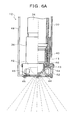
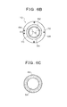
- FIGS. 6A , 6B, and 6C show a fourth embodiment of the electrification spray head 10 shown in FIG. 1 and FIG. 2 .
- FIG. 6A shows a cross section
- FIG. 6B shows a plan view viewed from the lower side
- FIG. 6C focuses on an induction electrode.
- the electrification spray head 10 of the fourth embodiment is characterized in that a head nozzle constituting a small-particle head unit and a large-particle head unit 10B is a rotating jet nozzle 62. More specifically, in the electrification spray head unit 10, a head main body 36 is screw-fixed with a distal end of the falling pipe 34 connected to the pipe from the pump unit 12. A cylindrical water-side electrode unit 40 is incorporated at the inside of the distal end of the head main body 36 via an insulating member 41.
- An earth cable 50 is wired from the voltage application unit 15, which is installed at the upper part as shown in FIG. 2 , with respect to the water-side electrode unit 40 and is connected to the water-side electrode unit 40, which is installed at the inside of the head main body 36 via the insulating member 41.
- the application voltage of the water-side electrode unit 40 is caused to be 0 volt and lead to the earth side by the connection of the earth cable 50.
- the rotating jet nozzle 62 is provided below the water-side electrode unit 40.
- the rotating jet nozzle 62 is rotatably placed inside a fixing member 43 via a bearing 64, and another fixing member 66 is disposed between there and the water-side electrode 40.
- the small-particle jetting slit 68 receives supply of the water-based fire-extinguishing agent, which is pressurized and supplied from the pump unit 12 of FIG. 1 , from the falling pipe 34; and the jetting nozzle converts the water-based fire-extinguishing agent into small particles having an average particle size within the range of 30 ⁇ m to 200 ⁇ m and sprays the particles when the water-based fire-extinguishing agent passes through the head main body 36 to the outside.
- the large-particle jetting slit 70 receives supply of the water-based fire-extinguishing agent, which is pressurized and supplied from the pump unit 12 of FIG. 1 , from the falling pipe 34; and the jetting nozzle converts the water-based fire-extinguishing agent into large particles having an average particle size within the range of 200 ⁇ m to 2000 ⁇ m and sprays the particles when the water-based fire-extinguishing agent passes through the head main body 36 to the outside.
- the small-particle jetting slits 68 and the large-particle jetting slits 70 are formed obliquely to the thickness direction. Therefore, while the rotating jet nozzle 62 is rotated by the jetting of the fire extinguishing agent from the small-particle jetting slits 68 and the large-particle jetting slits 70, the group of the fire-extinguishing-agent small particles and the group of the fire-extinguishing-agent large particles are spirally sprayed.
- the group of the fire-extinguishing-agent small particles sprayed from the small-particle jetting slits 68 is carried by the air current generated by the spraying of the group of the fire-extinguishing-agent large particles from the large-particle jetting slits 70 in this case, the group of the fire-extinguishing-agent small particles can be sprayed over a wide range together with the group of the fire-extinguishing-agent large particles, and the fire extinguishing agent in which the small particles and the large particles are mixed can be sprayed all over the protection zone by a small number of electrification spray heads 10.
- a cover 42 using an insulating material is fixed by screw-fixing with respect to a head main body 36 via a fixing member 43.
- the cover 42 is an approximately-cylindrical member and incorporates a ring-like induction electrode unit 44 in an open part in the lower side by screw-fixing of a stopper ring 46.
- the induction electrode unit 44 forms an opening 54, which allows the jetted particles from the small-particle jetting slits 68 and the large-particle jetting slits 70 to pass therethrough, at the center of a ring-like main body thereof.
- a voltage application cable 48 is wired from the voltage application unit 15 in the upper part shown in FIG. 2 ; and the voltage application cable 48 penetrates through the cover 42, which is composed of the insulating material, and is connected to the induction electrode unit 44 so that a voltage can be applied thereto.
- the voltage application unit 15 shown in FIG. 2 is operated by a control signal, which is from the linked control relaying device 20 shown in FIG. 1 , and applies a DC, AC, or pulsed application voltage of, for example, less than 20 kilovolts to the ring-like induction electrode unit 44 while the water-side electrode unit 40 serves as the earth side of 0 volt.
- the jetted small particles are electrified through the jetting process of converting the water-based fire-extinguishing agent to the jetted small particles having the average particle size in the range of 30 ⁇ m to 200 ⁇ m from the small-particle jetting slits 68 of the rotating jet nozzle 62.
- the jetted large particles are electrified through the jetting process of converting the water-based fire-extinguishing agent to the jetted large particles having the average particle size in the range of 200 ⁇ m to 2000 ⁇ m from the large-particle jetting slits 70, and the group of the electrified fire-extinguishing-agent small particles and the group of the fire-extinguishing-agent large particles can be mixed with each other by rotation of the rotating jet nozzle 62 and spirally sprayed.
- the nozzle structure becomes simple, the head can be downsized, and installation space and cost can be reduced.
- the various structures shown in above described embodiments can be applied to the electrification spray head 10 used in the present embodiment; however, the structure is not limited thereto, and an electrification spray head having an arbitrary structure can be used.
- the induction electrode unit side is to be at positive/negative application voltages, only positive application voltages, or only negative application voltages while the water-side electrode unit is at 0 volt can be also arbitrarily determined in accordance with needs depending on the situation of the burning member side serving as a fire extinguishing target.
- the present invention includes arbitrary modifications that do not impair the objects and advantages of the present invention, and the present invention is not limited by the numerical values shown in the above described embodiments.
Landscapes
- Health & Medical Sciences (AREA)
- Public Health (AREA)
- Business, Economics & Management (AREA)
- Emergency Management (AREA)
- Fire-Extinguishing By Fire Departments, And Fire-Extinguishing Equipment And Control Thereof (AREA)
Applications Claiming Priority (1)
| Application Number | Priority Date | Filing Date | Title |
|---|---|---|---|
| PCT/JP2009/058246 WO2010125627A1 (fr) | 2009-04-27 | 2009-04-27 | Equipement de prévention contre les incendies |
Publications (3)
| Publication Number | Publication Date |
|---|---|
| EP2425877A1 true EP2425877A1 (fr) | 2012-03-07 |
| EP2425877A4 EP2425877A4 (fr) | 2014-12-17 |
| EP2425877B1 EP2425877B1 (fr) | 2017-09-06 |
Family
ID=43031795
Family Applications (1)
| Application Number | Title | Priority Date | Filing Date |
|---|---|---|---|
| EP09843971.4A Not-in-force EP2425877B1 (fr) | 2009-04-27 | 2009-04-27 | Equipement de prévention contre les incendies |
Country Status (5)
| Country | Link |
|---|---|
| US (2) | US8365836B2 (fr) |
| EP (1) | EP2425877B1 (fr) |
| JP (1) | JP5281155B2 (fr) |
| CN (1) | CN102413878B (fr) |
| WO (1) | WO2010125627A1 (fr) |
Families Citing this family (8)
| Publication number | Priority date | Publication date | Assignee | Title |
|---|---|---|---|---|
| CN102223925B (zh) * | 2009-01-19 | 2014-07-09 | 报知机股份有限公司 | 消防设备及喷洒方法 |
| CN102413878B (zh) * | 2009-04-27 | 2013-07-24 | 报知机股份有限公司 | 防火设备 |
| WO2013171880A1 (fr) * | 2012-05-17 | 2013-11-21 | ホーチキ株式会社 | Appareil de prévention des incendies, appareil de dispersion de charge, tête de dispersion de charge, procédé de dispersion d'agent extincteur, et procédé de dispersion de charge |
| US20150151150A1 (en) * | 2012-07-03 | 2015-06-04 | Marioff Corporation | Fire suppression system |
| DE102016212612B4 (de) * | 2016-07-11 | 2020-01-30 | Minimax Gmbh & Co. Kg | Feuerlöschvorrichtung zur Installation in einem Raum und zur Brandbekämpfung in mehreren Sektoren des Raums, sowie Feuerlöschanlage mit selbiger |
| TWI799647B (zh) * | 2018-10-02 | 2023-04-21 | 日商高壓股份有限公司 | 液態滅火劑用噴射頭 |
| CN111790087B (zh) * | 2020-07-28 | 2024-10-18 | 西安科技大学 | 一种扑救高位火源的带电水雾导流方法及其装置 |
| CN116159269A (zh) * | 2023-03-22 | 2023-05-26 | 北京泰和佳科技股份有限公司 | 一种智能自感温定向灭火装置 |
Family Cites Families (17)
| Publication number | Priority date | Publication date | Assignee | Title |
|---|---|---|---|---|
| JPS58174258A (ja) * | 1982-04-05 | 1983-10-13 | Minato Seiyaku Kk | 静電消煙用帯電霧化粒子発生装置 |
| GB8432272D0 (en) * | 1984-12-20 | 1985-01-30 | Ici Plc | Spraying apparatus |
| JPH03186277A (ja) * | 1989-12-18 | 1991-08-14 | Nagao Kogyo:Kk | 消火消煙装置 |
| US5353879A (en) | 1989-12-18 | 1994-10-11 | Kabushiki Kaisha Nagao Kogyo | Door having smoke reducing apparatus associated therewith |
| JPH08266676A (ja) * | 1995-03-30 | 1996-10-15 | Nohmi Bosai Ltd | 消火液複合噴射ノズル |
| JPH09299503A (ja) * | 1996-05-16 | 1997-11-25 | Hochiki Corp | 固定式消火設備の散水方法及び消火用散水ノズル |
| JPH10118214A (ja) | 1996-10-16 | 1998-05-12 | Bunka Shutter Co Ltd | ウォーターミストを利用した消火、消煙方法及びその装置 |
| JP4049284B2 (ja) | 1997-10-30 | 2008-02-20 | 日本ドライケミカル株式会社 | ウォーターミスト消火設備 |
| US6189622B1 (en) * | 1999-05-11 | 2001-02-20 | Le Group-Conseil Lasalle, Inc. | Nozzle for fighting fires in buildings |
| JP4621337B2 (ja) * | 2000-07-05 | 2011-01-26 | ヤマトプロテック株式会社 | 消火用ノズル及び消火方法 |
| ITMI20022283A1 (it) * | 2002-10-25 | 2004-04-26 | Ciodue Acqua S R L | Testina per spruzzatore, particolarmente per impianti antincendio |
| CN2691650Y (zh) * | 2004-04-01 | 2005-04-13 | 袁野 | 电子灭火器 |
| KR100585936B1 (ko) * | 2004-07-16 | 2006-06-08 | 탱크테크 (주) | 소화용 분무장치 |
| FI116661B (fi) * | 2004-12-15 | 2006-01-31 | Marioff Corp Oy | Menetelmä väliaineen suihkuttamiseksi ja suihkutussuutin |
| JP2007279865A (ja) | 2006-04-04 | 2007-10-25 | Japan Servo Co Ltd | 磁気式回転リンク |
| CN102223925B (zh) * | 2009-01-19 | 2014-07-09 | 报知机股份有限公司 | 消防设备及喷洒方法 |
| CN102413878B (zh) * | 2009-04-27 | 2013-07-24 | 报知机股份有限公司 | 防火设备 |
-
2009
- 2009-04-27 CN CN2009801589839A patent/CN102413878B/zh not_active Expired - Fee Related
- 2009-04-27 WO PCT/JP2009/058246 patent/WO2010125627A1/fr not_active Ceased
- 2009-04-27 EP EP09843971.4A patent/EP2425877B1/fr not_active Not-in-force
- 2009-04-27 JP JP2011511198A patent/JP5281155B2/ja active Active
-
2011
- 2011-09-14 US US13/232,066 patent/US8365836B2/en not_active Expired - Fee Related
-
2012
- 2012-12-27 US US13/728,251 patent/US8505641B2/en not_active Expired - Fee Related
Also Published As
| Publication number | Publication date |
|---|---|
| JPWO2010125627A1 (ja) | 2012-10-25 |
| US8365836B2 (en) | 2013-02-05 |
| CN102413878A (zh) | 2012-04-11 |
| US20130119169A1 (en) | 2013-05-16 |
| EP2425877B1 (fr) | 2017-09-06 |
| JP5281155B2 (ja) | 2013-09-04 |
| CN102413878B (zh) | 2013-07-24 |
| US20120000677A1 (en) | 2012-01-05 |
| US8505641B2 (en) | 2013-08-13 |
| WO2010125627A1 (fr) | 2010-11-04 |
| EP2425877A4 (fr) | 2014-12-17 |
Similar Documents
| Publication | Publication Date | Title |
|---|---|---|
| US8505641B2 (en) | Electrification spray head | |
| EP3292889B1 (fr) | Tête de pulvérisation d'électrification | |
| JP4989419B2 (ja) | 火災防災設備及び散布方法 | |
| EP2258449B1 (fr) | Dispositif de tête de buse de lutte contre l'incendie | |
| JP5797906B2 (ja) | 帯電散布ヘッド及び帯電散布装置 | |
| JP5797905B2 (ja) | 帯電散布ヘッド及び帯電散布装置 | |
| JP2009103335A (ja) | 噴霧冷房設備及び噴霧方法 | |
| TWI397434B (zh) | Fire disaster prevention equipment | |
| WO1997043046A1 (fr) | Buse | |
| CN103463777A (zh) | 带电喷洒喷头 | |
| TWI383815B (zh) | Fire and disaster prevention equipment, spraying methods, spray air-conditioning equipment and spray methods | |
| JP2013226420A (ja) | 帯電散布ヘッド | |
| JP5270778B2 (ja) | 帯電散布ヘッド | |
| TWI564054B (zh) | Fire and disaster prevention equipment and spray air-conditioning equipment charged spray head | |
| KR101958514B1 (ko) | 화재 예방 장치, 대전 살포 장치, 대전 살포 헤드, 소화제 살포 방법 및 대전 살포 방법 | |
| JP2012157431A (ja) | 火災防災装置、帯電散布ヘッド及び帯電散布方法 | |
| WO2013179408A1 (fr) | Appareil de lutte anti-incendie, appareil de dispersion chargée, tête de dispersion chargée, procédé de dispersion d'agent d'extinction d'incendie, et procédé de dispersion chargée | |
| AU2012200554A1 (en) | Electrification spray head | |
| WO2013179416A1 (fr) | Appareil de lutte anti-incendie, tête de dispersion chargée et procédé de dispersion chargée |
Legal Events
| Date | Code | Title | Description |
|---|---|---|---|
| PUAI | Public reference made under article 153(3) epc to a published international application that has entered the european phase |
Free format text: ORIGINAL CODE: 0009012 |
|
| 17P | Request for examination filed |
Effective date: 20111121 |
|
| AK | Designated contracting states |
Kind code of ref document: A1 Designated state(s): AT BE BG CH CY CZ DE DK EE ES FI FR GB GR HR HU IE IS IT LI LT LU LV MC MK MT NL NO PL PT RO SE SI SK TR |
|
| DAX | Request for extension of the european patent (deleted) | ||
| A4 | Supplementary search report drawn up and despatched |
Effective date: 20141118 |
|
| RIC1 | Information provided on ipc code assigned before grant |
Ipc: A62C 31/05 20060101AFI20141112BHEP Ipc: A62C 99/00 20100101ALI20141112BHEP Ipc: A62C 35/68 20060101ALI20141112BHEP |
|
| GRAP | Despatch of communication of intention to grant a patent |
Free format text: ORIGINAL CODE: EPIDOSNIGR1 |
|
| INTG | Intention to grant announced |
Effective date: 20170321 |
|
| GRAS | Grant fee paid |
Free format text: ORIGINAL CODE: EPIDOSNIGR3 |
|
| GRAA | (expected) grant |
Free format text: ORIGINAL CODE: 0009210 |
|
| AK | Designated contracting states |
Kind code of ref document: B1 Designated state(s): AT BE BG CH CY CZ DE DK EE ES FI FR GB GR HR HU IE IS IT LI LT LU LV MC MK MT NL NO PL PT RO SE SI SK TR |
|
| REG | Reference to a national code |
Ref country code: GB Ref legal event code: FG4D |
|
| RIN1 | Information on inventor provided before grant (corrected) |
Inventor name: HAYASHI, TATSUYA Inventor name: YOSHIDA, TETSUO Inventor name: TSUJI, TOSHIHIDE |
|
| REG | Reference to a national code |
Ref country code: CH Ref legal event code: EP Ref country code: AT Ref legal event code: REF Ref document number: 925239 Country of ref document: AT Kind code of ref document: T Effective date: 20170915 |
|
| REG | Reference to a national code |
Ref country code: IE Ref legal event code: FG4D |
|
| REG | Reference to a national code |
Ref country code: DE Ref legal event code: R096 Ref document number: 602009048262 Country of ref document: DE |
|
| REG | Reference to a national code |
Ref country code: NL Ref legal event code: MP Effective date: 20170906 |
|
| REG | Reference to a national code |
Ref country code: LT Ref legal event code: MG4D |
|
| PG25 | Lapsed in a contracting state [announced via postgrant information from national office to epo] |
Ref country code: HR Free format text: LAPSE BECAUSE OF FAILURE TO SUBMIT A TRANSLATION OF THE DESCRIPTION OR TO PAY THE FEE WITHIN THE PRESCRIBED TIME-LIMIT Effective date: 20170906 Ref country code: LT Free format text: LAPSE BECAUSE OF FAILURE TO SUBMIT A TRANSLATION OF THE DESCRIPTION OR TO PAY THE FEE WITHIN THE PRESCRIBED TIME-LIMIT Effective date: 20170906 Ref country code: SE Free format text: LAPSE BECAUSE OF FAILURE TO SUBMIT A TRANSLATION OF THE DESCRIPTION OR TO PAY THE FEE WITHIN THE PRESCRIBED TIME-LIMIT Effective date: 20170906 Ref country code: FI Free format text: LAPSE BECAUSE OF FAILURE TO SUBMIT A TRANSLATION OF THE DESCRIPTION OR TO PAY THE FEE WITHIN THE PRESCRIBED TIME-LIMIT Effective date: 20170906 Ref country code: NO Free format text: LAPSE BECAUSE OF FAILURE TO SUBMIT A TRANSLATION OF THE DESCRIPTION OR TO PAY THE FEE WITHIN THE PRESCRIBED TIME-LIMIT Effective date: 20171206 |
|
| REG | Reference to a national code |
Ref country code: AT Ref legal event code: MK05 Ref document number: 925239 Country of ref document: AT Kind code of ref document: T Effective date: 20170906 |
|
| PG25 | Lapsed in a contracting state [announced via postgrant information from national office to epo] |
Ref country code: BG Free format text: LAPSE BECAUSE OF FAILURE TO SUBMIT A TRANSLATION OF THE DESCRIPTION OR TO PAY THE FEE WITHIN THE PRESCRIBED TIME-LIMIT Effective date: 20171206 Ref country code: ES Free format text: LAPSE BECAUSE OF FAILURE TO SUBMIT A TRANSLATION OF THE DESCRIPTION OR TO PAY THE FEE WITHIN THE PRESCRIBED TIME-LIMIT Effective date: 20170906 Ref country code: LV Free format text: LAPSE BECAUSE OF FAILURE TO SUBMIT A TRANSLATION OF THE DESCRIPTION OR TO PAY THE FEE WITHIN THE PRESCRIBED TIME-LIMIT Effective date: 20170906 Ref country code: GR Free format text: LAPSE BECAUSE OF FAILURE TO SUBMIT A TRANSLATION OF THE DESCRIPTION OR TO PAY THE FEE WITHIN THE PRESCRIBED TIME-LIMIT Effective date: 20171207 |
|
| REG | Reference to a national code |
Ref country code: FR Ref legal event code: PLFP Year of fee payment: 10 |
|
| PG25 | Lapsed in a contracting state [announced via postgrant information from national office to epo] |
Ref country code: NL Free format text: LAPSE BECAUSE OF FAILURE TO SUBMIT A TRANSLATION OF THE DESCRIPTION OR TO PAY THE FEE WITHIN THE PRESCRIBED TIME-LIMIT Effective date: 20170906 |
|
| PG25 | Lapsed in a contracting state [announced via postgrant information from national office to epo] |
Ref country code: RO Free format text: LAPSE BECAUSE OF FAILURE TO SUBMIT A TRANSLATION OF THE DESCRIPTION OR TO PAY THE FEE WITHIN THE PRESCRIBED TIME-LIMIT Effective date: 20170906 Ref country code: PL Free format text: LAPSE BECAUSE OF FAILURE TO SUBMIT A TRANSLATION OF THE DESCRIPTION OR TO PAY THE FEE WITHIN THE PRESCRIBED TIME-LIMIT Effective date: 20170906 Ref country code: CZ Free format text: LAPSE BECAUSE OF FAILURE TO SUBMIT A TRANSLATION OF THE DESCRIPTION OR TO PAY THE FEE WITHIN THE PRESCRIBED TIME-LIMIT Effective date: 20170906 |
|
| PG25 | Lapsed in a contracting state [announced via postgrant information from national office to epo] |
Ref country code: AT Free format text: LAPSE BECAUSE OF FAILURE TO SUBMIT A TRANSLATION OF THE DESCRIPTION OR TO PAY THE FEE WITHIN THE PRESCRIBED TIME-LIMIT Effective date: 20170906 Ref country code: IT Free format text: LAPSE BECAUSE OF FAILURE TO SUBMIT A TRANSLATION OF THE DESCRIPTION OR TO PAY THE FEE WITHIN THE PRESCRIBED TIME-LIMIT Effective date: 20170906 Ref country code: SK Free format text: LAPSE BECAUSE OF FAILURE TO SUBMIT A TRANSLATION OF THE DESCRIPTION OR TO PAY THE FEE WITHIN THE PRESCRIBED TIME-LIMIT Effective date: 20170906 Ref country code: IS Free format text: LAPSE BECAUSE OF FAILURE TO SUBMIT A TRANSLATION OF THE DESCRIPTION OR TO PAY THE FEE WITHIN THE PRESCRIBED TIME-LIMIT Effective date: 20180106 Ref country code: EE Free format text: LAPSE BECAUSE OF FAILURE TO SUBMIT A TRANSLATION OF THE DESCRIPTION OR TO PAY THE FEE WITHIN THE PRESCRIBED TIME-LIMIT Effective date: 20170906 |
|
| REG | Reference to a national code |
Ref country code: DE Ref legal event code: R097 Ref document number: 602009048262 Country of ref document: DE |
|
| PLBE | No opposition filed within time limit |
Free format text: ORIGINAL CODE: 0009261 |
|
| STAA | Information on the status of an ep patent application or granted ep patent |
Free format text: STATUS: NO OPPOSITION FILED WITHIN TIME LIMIT |
|
| PG25 | Lapsed in a contracting state [announced via postgrant information from national office to epo] |
Ref country code: DK Free format text: LAPSE BECAUSE OF FAILURE TO SUBMIT A TRANSLATION OF THE DESCRIPTION OR TO PAY THE FEE WITHIN THE PRESCRIBED TIME-LIMIT Effective date: 20170906 |
|
| 26N | No opposition filed |
Effective date: 20180607 |
|
| PG25 | Lapsed in a contracting state [announced via postgrant information from national office to epo] |
Ref country code: SI Free format text: LAPSE BECAUSE OF FAILURE TO SUBMIT A TRANSLATION OF THE DESCRIPTION OR TO PAY THE FEE WITHIN THE PRESCRIBED TIME-LIMIT Effective date: 20170906 |
|
| PG25 | Lapsed in a contracting state [announced via postgrant information from national office to epo] |
Ref country code: MC Free format text: LAPSE BECAUSE OF FAILURE TO SUBMIT A TRANSLATION OF THE DESCRIPTION OR TO PAY THE FEE WITHIN THE PRESCRIBED TIME-LIMIT Effective date: 20170906 |
|
| REG | Reference to a national code |
Ref country code: CH Ref legal event code: PL |
|
| REG | Reference to a national code |
Ref country code: BE Ref legal event code: MM Effective date: 20180430 |
|
| REG | Reference to a national code |
Ref country code: IE Ref legal event code: MM4A |
|
| PG25 | Lapsed in a contracting state [announced via postgrant information from national office to epo] |
Ref country code: LU Free format text: LAPSE BECAUSE OF NON-PAYMENT OF DUE FEES Effective date: 20180427 |
|
| PG25 | Lapsed in a contracting state [announced via postgrant information from national office to epo] |
Ref country code: LI Free format text: LAPSE BECAUSE OF NON-PAYMENT OF DUE FEES Effective date: 20180430 Ref country code: BE Free format text: LAPSE BECAUSE OF NON-PAYMENT OF DUE FEES Effective date: 20180430 Ref country code: CH Free format text: LAPSE BECAUSE OF NON-PAYMENT OF DUE FEES Effective date: 20180430 |
|
| PG25 | Lapsed in a contracting state [announced via postgrant information from national office to epo] |
Ref country code: IE Free format text: LAPSE BECAUSE OF NON-PAYMENT OF DUE FEES Effective date: 20180427 |
|
| PG25 | Lapsed in a contracting state [announced via postgrant information from national office to epo] |
Ref country code: MT Free format text: LAPSE BECAUSE OF NON-PAYMENT OF DUE FEES Effective date: 20180427 |
|
| PG25 | Lapsed in a contracting state [announced via postgrant information from national office to epo] |
Ref country code: TR Free format text: LAPSE BECAUSE OF FAILURE TO SUBMIT A TRANSLATION OF THE DESCRIPTION OR TO PAY THE FEE WITHIN THE PRESCRIBED TIME-LIMIT Effective date: 20170906 |
|
| PG25 | Lapsed in a contracting state [announced via postgrant information from national office to epo] |
Ref country code: HU Free format text: LAPSE BECAUSE OF FAILURE TO SUBMIT A TRANSLATION OF THE DESCRIPTION OR TO PAY THE FEE WITHIN THE PRESCRIBED TIME-LIMIT; INVALID AB INITIO Effective date: 20090427 Ref country code: PT Free format text: LAPSE BECAUSE OF FAILURE TO SUBMIT A TRANSLATION OF THE DESCRIPTION OR TO PAY THE FEE WITHIN THE PRESCRIBED TIME-LIMIT Effective date: 20170906 |
|
| PG25 | Lapsed in a contracting state [announced via postgrant information from national office to epo] |
Ref country code: CY Free format text: LAPSE BECAUSE OF FAILURE TO SUBMIT A TRANSLATION OF THE DESCRIPTION OR TO PAY THE FEE WITHIN THE PRESCRIBED TIME-LIMIT Effective date: 20170906 Ref country code: MK Free format text: LAPSE BECAUSE OF NON-PAYMENT OF DUE FEES Effective date: 20170906 |
|
| REG | Reference to a national code |
Ref country code: DE Ref legal event code: R082 Ref document number: 602009048262 Country of ref document: DE Representative=s name: HL KEMPNER PATENTANWALT, RECHTSANWALT, SOLICIT, DE |
|
| PGFP | Annual fee paid to national office [announced via postgrant information from national office to epo] |
Ref country code: DE Payment date: 20210330 Year of fee payment: 13 |
|
| PGFP | Annual fee paid to national office [announced via postgrant information from national office to epo] |
Ref country code: GB Payment date: 20220303 Year of fee payment: 14 |
|
| PGFP | Annual fee paid to national office [announced via postgrant information from national office to epo] |
Ref country code: FR Payment date: 20220308 Year of fee payment: 14 |
|
| REG | Reference to a national code |
Ref country code: DE Ref legal event code: R119 Ref document number: 602009048262 Country of ref document: DE |
|
| PG25 | Lapsed in a contracting state [announced via postgrant information from national office to epo] |
Ref country code: DE Free format text: LAPSE BECAUSE OF NON-PAYMENT OF DUE FEES Effective date: 20221103 |
|
| GBPC | Gb: european patent ceased through non-payment of renewal fee |
Effective date: 20230427 |
|
| PG25 | Lapsed in a contracting state [announced via postgrant information from national office to epo] |
Ref country code: GB Free format text: LAPSE BECAUSE OF NON-PAYMENT OF DUE FEES Effective date: 20230427 |
|
| PG25 | Lapsed in a contracting state [announced via postgrant information from national office to epo] |
Ref country code: GB Free format text: LAPSE BECAUSE OF NON-PAYMENT OF DUE FEES Effective date: 20230427 Ref country code: FR Free format text: LAPSE BECAUSE OF NON-PAYMENT OF DUE FEES Effective date: 20230430 |