EP2426018A1 - Mécanisme de levier de pédale pour un véhicule - Google Patents
Mécanisme de levier de pédale pour un véhicule Download PDFInfo
- Publication number
- EP2426018A1 EP2426018A1 EP11006641A EP11006641A EP2426018A1 EP 2426018 A1 EP2426018 A1 EP 2426018A1 EP 11006641 A EP11006641 A EP 11006641A EP 11006641 A EP11006641 A EP 11006641A EP 2426018 A1 EP2426018 A1 EP 2426018A1
- Authority
- EP
- European Patent Office
- Prior art keywords
- guide element
- spring guide
- lever
- lever arm
- pedal
- Prior art date
- Legal status (The legal status is an assumption and is not a legal conclusion. Google has not performed a legal analysis and makes no representation as to the accuracy of the status listed.)
- Withdrawn
Links
- 230000006835 compression Effects 0.000 claims abstract description 27
- 238000007906 compression Methods 0.000 claims abstract description 27
- 239000002131 composite material Substances 0.000 claims 1
- 239000012530 fluid Substances 0.000 description 2
- 102000004315 Forkhead Transcription Factors Human genes 0.000 description 1
- 108090000852 Forkhead Transcription Factors Proteins 0.000 description 1
- 230000004913 activation Effects 0.000 description 1
- 230000002411 adverse Effects 0.000 description 1
- 238000010276 construction Methods 0.000 description 1
- 238000006073 displacement reaction Methods 0.000 description 1
- 230000002349 favourable effect Effects 0.000 description 1
- 238000001746 injection moulding Methods 0.000 description 1
- 238000004519 manufacturing process Methods 0.000 description 1
- 238000000034 method Methods 0.000 description 1
- 238000003825 pressing Methods 0.000 description 1
Images




Classifications
-
- B—PERFORMING OPERATIONS; TRANSPORTING
- B60—VEHICLES IN GENERAL
- B60T—VEHICLE BRAKE CONTROL SYSTEMS OR PARTS THEREOF; BRAKE CONTROL SYSTEMS OR PARTS THEREOF, IN GENERAL; ARRANGEMENT OF BRAKING ELEMENTS ON VEHICLES IN GENERAL; PORTABLE DEVICES FOR PREVENTING UNWANTED MOVEMENT OF VEHICLES; VEHICLE MODIFICATIONS TO FACILITATE COOLING OF BRAKES
- B60T7/00—Brake-action initiating means
- B60T7/02—Brake-action initiating means for personal initiation
- B60T7/04—Brake-action initiating means for personal initiation foot actuated
- B60T7/06—Disposition of pedal
-
- G—PHYSICS
- G05—CONTROLLING; REGULATING
- G05G—CONTROL DEVICES OR SYSTEMS INSOFAR AS CHARACTERISED BY MECHANICAL FEATURES ONLY
- G05G1/00—Controlling members, e.g. knobs or handles; Assemblies or arrangements thereof; Indicating position of controlling members
- G05G1/30—Controlling members actuated by foot
-
- G—PHYSICS
- G05—CONTROLLING; REGULATING
- G05G—CONTROL DEVICES OR SYSTEMS INSOFAR AS CHARACTERISED BY MECHANICAL FEATURES ONLY
- G05G7/00—Manually-actuated control mechanisms provided with one single controlling member co-operating with one single controlled member; Details thereof
- G05G7/02—Manually-actuated control mechanisms provided with one single controlling member co-operating with one single controlled member; Details thereof characterised by special provisions for conveying or converting motion, or for acting at a distance
- G05G7/04—Manually-actuated control mechanisms provided with one single controlling member co-operating with one single controlled member; Details thereof characterised by special provisions for conveying or converting motion, or for acting at a distance altering the ratio of motion or force between controlling member and controlled member as a function of the position of the controlling member
Definitions
- the invention relates to a pedal mechanism for a vehicle, in particular a motor vehicle, according to the preamble of claim 1 of the invention.
- the coil spring is arranged, which in turn at one end via an end flange of the inner spring guide on the cup-shaped fastener and thus on the second lever arm of the pedal and the other end via a roller assembly and a bearing block fixedly mounted cam element for influencing the spring characteristic of the coil spring over the spring travel thereof is supported on the bearing block.
- a fastening axis for fastening the Studentstot Vietnamesefederan ever on the bearing block.
- the roller assembly and the mounting axis slidably guided in zugordneten slots of the inner spring guide are the roller assembly and the mounting axis slidably guided in zugordneten slots of the inner spring guide.
- the Kochtot Vietnamesefederan is formed by two telescoping support members between which a helical compression spring is supported, with a second lever arm of a pedal facing the end of a support member with said lever arm and an end facing away from the second lever arm of the pedal end the other support member is connected to a bearing block of the clutch pedals.
- the object of the invention is to provide a pedal system for a vehicle, in particular motor vehicle, with an alternative Götot Vietnamesefederan extract which is simple and inexpensive to manufacture and assemble and ensures safe operation with low space requirement.
- the object is characterized in that the Kochtot Vietnamesefederan eleven comprises a first outer and a second inner spring guide element, wherein the first outer spring guide element is formed with an end facing away from the second lever arm of the pedal lever and an end facing away from the second lever arm and with a side wall, wherein the second inner spring guide element within the first outer spring guide element, an annular space between the first outer and the second inner spring guide element forming, is slidably mounted in the axial direction of the first outer spring guide element, wherein i at least one helical compression spring is arranged within said annular space, which in turn is supported at one end on the first outer spring guide element and the other on the second inner spring guide element, wherein the first outer spring guide
- a pedal mechanism is provided with a compact Götot Vietnamesefederan extract whose construction and functional space is reduced to a minimum, since the necessary connections thereof to the pedal lever and the Bearing block are arranged immediately adjacent to each other, namely at the ends of the spring guide elements, which face the pedal lever or its second lever arm.
- first outer and the second inner spring guide member may mutually corresponding guide means for defined axial guidance of the second inner spring guide element in the first outer spring guide element, whereby the function of the Studentstot Vietnamesefederan ever impairing malpositions of the two relatively telescoping spring guide elements are advantageously avoidable.
- the guide means can be designed such that the pot-, pipe- or rod-shaped second inner spring guide element is slidably mounted in both ends in the first outer spring guide element, resulting in an increased reliability of Kochtot Vietnamesefederan ever results.
- the annular space may be selected depending on the diameter of the helical compression spring in its radial extent such that a sliding side support of the at least one helical compression spring by at least one of the spring guide elements on the spring travel, preferably total spring travel is permitted. Such side support prevents any adverse for the functioning of the Kochtot Vietnamesefederan ever lateral buckling of the helical compression spring.
- first outer and second inner spring guide element have mutually corresponding and an axial relative movement between the two spring guide elements limiting and a mounting assembly causing interlocking means.
- the Mathtot Vietnamesefederanssen can be advantageously provided as a preassembled component with captive held together individual components as well as with biased helical compression spring for the final assembly process of a vehicle, in which case only two attachment measures are required.
- the connection of the second lever arm to the second inner spring guide element may be effected by a clevis connection, which is formed by a clevis, which in turn is positively connected to a clevis receptacle connected.
- the invention also relates to a vehicle, in particular a motor vehicle, with a pedal mechanism of the type described above.
- Fig. 1 and 2 show a pedal mechanism 1 for a vehicle, in particular motor vehicle, for example, hydraulic clutch actuation, wherein known to be applied by a driver to a pedal lever 2 pedal force by means of a non-illustrated, but known master cylinder and slave cylinder hydraulically translated and forwarded to a releaser of a likewise known per se and thus not shown friction clutch.
- the foot force of the vehicle driver is transmitted to the piston of said master cylinder via the pedal lever 2, which is mounted so as to be pivotable about a rotation axis 4 in a bearing block 3, and a linkage, not shown in more detail.
- the fluid pressure generated in the pressure chamber of the master cylinder propagates in associated fluid lines to the slave cylinder and causes the piston of the slave cylinder, a force that operates via one or more actuators, such as a plunger with attached release lever the releaser and the clutch disengages respectively opens.
- actuators such as a plunger with attached release lever the releaser and the clutch disengages respectively opens.
- For engaging respectively closing the clutch usually presses a diaphragm spring of the clutch on the releaser, the release lever and the plunger back the piston of slave cylinder and master cylinder together with the pedal lever 2 in the starting position.
- the pedal lever 2 carries at the free end of a first lever arm 2a a pedal plate 5 and has a first lever arm 2a largely offset at right angles second lever arm 2b whose free end is connected to a Studentstot Vietnamesefederantechnische 6. Further, a known return spring 7, in the present case in the form of a helical tension spring is provided, which is fixed at one end to the bearing block 3 and the other end on the pedal lever 2 and the return of the same after its activation of the pedal lever 2 supported in its initial position.
- the Mattertot Vietnamesefederan extract 6 in turn has a first outer spring guide element 8 and a sliding in the same respectively telescoping second inner.
- Spring guide element 9 (see. 4 to 6 ).
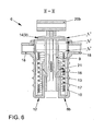
- the first outer spring guide element 8 is predominantly pot-shaped with an end 8a facing the second lever arm 2b of the pedal lever 2 and an end 8b facing away from the second lever arm 2b and with a side wall 10 closed in sections.
- the pot opening 11 is lever arm side, whereas the bottom of the pot 12 forms the end 8b facing away from the second lever arm 2b.
- the second inner spring guide element 9 in turn is predominantly tubular and axially guided with its from the second lever arm 2b remote end 9b within a pot bottom 12 to the pot opening 11 axially extending first guide means 13 in the form of a tubular receptacle.
- an end flange 14 is provided, which in turn is radially supported on the inner contour of the side wall 10 and axially guided in groove-shaped second guide means 15.
- annular space 16 is formed between the first outer spring guide element 8 and the second inner spring guide element 9, in which a helical compression spring 17 is arranged.
- the helical compression spring 17 is supported at one end on the first outer spring guide element 8, in this case at the bottom of the pot 12 thereof, and at the other end at said end flange 14 of the second inner spring guide element 9.
- the formed annulus 16 is selected depending on the diameter of the helical compression spring 17 in its radial extent or dimensioned that a sliding side support of the helical compression spring 17 by at least one of the spring guide elements 8, 9 over the spring travel, preferably over the entire travel is allowed.
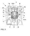
- the first outer spring guide element 8 has at its the second lever arm 2b of the pedal lever 2 facing the end 8a via two radially oppositely disposed and from the side wall 10 of the first outer spring guide element 8 radially parked bearing means 18 in the form of trunnions, which in turn in corresponding receptacles 19 of the Side cheeks 3a, 3b of the bearing block 3 are pivotally mounted.
- a so-called clevis connection 20 is provided, which is formed by a fork end 20a arranged at the free end of the second lever arm 2b of the pedal lever 2 and a fork head receptacle 20b arranged on the lever arm end 9a of the second inner spring guide element 9 ( Fig. 1 to 3 ).
- first outer and second inner spring guide element 8, 9 mutually corresponding and an axial relative movement between the two spring guide elements 8, 9 limiting and a Montageverbund effecting positive locking means 21 in the form of latching hooks on the second inner spring guide element 9 and undercuts on the first guide means 13 of the first outer.
- the assembly of the Studentstot Vietnamesefederan extract 6 is preferably carried out such that initially the first outer spring guide member 8 equipped with the helical compression spring 17 and subsequently completed with the second inner spring guide element 9 by the tubular part of the second inner spring guide element 9 in the tubular first guide means 13 of the first outer spring guide element 5 is inserted axially until the said positive locking means 21 engage.
- the length of the helical compression spring 17 is preferably chosen such that it already experiences a certain bias.
- the above exemplary embodiment is based on a cup-shaped first outer and a tubular second inner spring guiding element 8, 9.
- the invention is not limited to this selected embodiment, but for the skilled person certainly comprehensible under the condition of forming an annular space 16 and ensuring a radial support and axial displacement of the second inner spring guide element 9 in the first outer spring guide element 8 also a first outer guide element 8, which tubular and a second inner guide member 9, which is pot-shaped or rod-shaped (not shown in detail).
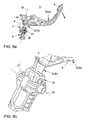
- the pedal lever 2 is in accordance with Fig. 7a, 7b at a time “t 1 " (initial position) for releasing the clutch operated respectively according to Fig. 7a Pressed down, the second inner spring guide element 9 is first pressed against the spring force of the helical compression spring 17 in the cup-shaped first outer spring guide element 8, while the first outer spring guide element 8 is supported on the bearing block 3.
- a formed by the clevis connection 20 bearing point 22 is initially in an initial position laterally outside of an imaginary connecting line 23 which in a common plane arranged on the axis of rotation 4 of the pedal lever 2 bearing point 24 with a arranged on the axis of rotation 25 of the first outer spring guide element 8 bearing point 26th combines.
Landscapes
- Engineering & Computer Science (AREA)
- Physics & Mathematics (AREA)
- General Physics & Mathematics (AREA)
- Automation & Control Theory (AREA)
- Transportation (AREA)
- Mechanical Engineering (AREA)
- Arrangement And Mounting Of Devices That Control Transmission Of Motive Force (AREA)
- Mechanical Control Devices (AREA)
Applications Claiming Priority (1)
| Application Number | Priority Date | Filing Date | Title |
|---|---|---|---|
| DE102010044417.0A DE102010044417B4 (de) | 2010-09-04 | 2010-09-04 | Fußhebelwerk für ein Fahrzeug |
Publications (1)
| Publication Number | Publication Date |
|---|---|
| EP2426018A1 true EP2426018A1 (fr) | 2012-03-07 |
Family
ID=44644876
Family Applications (1)
| Application Number | Title | Priority Date | Filing Date |
|---|---|---|---|
| EP11006641A Withdrawn EP2426018A1 (fr) | 2010-09-04 | 2011-08-12 | Mécanisme de levier de pédale pour un véhicule |
Country Status (2)
| Country | Link |
|---|---|
| EP (1) | EP2426018A1 (fr) |
| DE (1) | DE102010044417B4 (fr) |
Cited By (4)
| Publication number | Priority date | Publication date | Assignee | Title |
|---|---|---|---|---|
| CN105365795A (zh) * | 2014-08-07 | 2016-03-02 | 株式会社F.泰克 | 车辆用踏板臂 |
| CN107585024A (zh) * | 2016-07-06 | 2018-01-16 | Zf腓特烈斯哈芬股份公司 | 踏板力模拟组件以及机动车 |
| CN107589778A (zh) * | 2016-07-06 | 2018-01-16 | Zf腓特烈斯哈芬股份公司 | 踏板力模拟组件以及机动车 |
| CN108638856A (zh) * | 2017-03-15 | 2018-10-12 | Zf腓特烈斯哈芬股份公司 | 踏板作用力模拟组件以及机动车 |
Families Citing this family (3)
| Publication number | Priority date | Publication date | Assignee | Title |
|---|---|---|---|---|
| DE102012010084B4 (de) * | 2012-05-23 | 2019-11-28 | Volkswagen Aktiengesellschaft | Übertotpunktfeder-Anordnung |
| DE102014217199B3 (de) * | 2014-08-28 | 2016-01-14 | Ford Global Technologies, Llc | Kupplungspedalsystem sowie Geberzylinder für ein Kupplungspedalsystem eines Fahrzeugs |
| DE102016212354A1 (de) * | 2016-07-06 | 2018-01-11 | Zf Friedrichshafen Ag | Pedalkraftsimulationsanordnung sowie Kraftfahrzeug |
Citations (8)
| Publication number | Priority date | Publication date | Assignee | Title |
|---|---|---|---|---|
| DE1235153B (de) * | 1965-06-24 | 1967-02-23 | Daimler Benz Ag | Einrichtung zur Unterstuetzung der Pedalkraft, vorzugsweise fuer die Betaetigung einer ausrueck-baren Fahrzeugkupplung, insbesondere Hauptkupplung fuer Kraftfahrzeuge |
| DE2262878A1 (de) * | 1972-12-22 | 1974-07-11 | Porsche Ag | Vorrichtung zum unterstuetzen der pedalkraft bei kraftfahrzeugkupplungen |
| FR2458433A1 (fr) * | 1979-06-07 | 1981-01-02 | Volkswagenwerk Ag | Dispositif d'actionnement d'un embrayage a disques de vehicule automobile, en particulier de camion |
| EP0169138A2 (fr) * | 1984-07-20 | 1986-01-22 | Automobiles Peugeot | Commande de débrayage pour véhicule automobile, équipée d'un ressort d'assistance |
| DE20220483U1 (de) | 2002-05-15 | 2003-10-23 | INNOTEC Forschungs- und Entwicklungs-GmbH, 95615 Marktredwitz | Pedalerie-Koppelglied für ein Kraftfahrzeug |
| EP1596268A2 (fr) | 2004-05-14 | 2005-11-16 | Audi Ag | Dispositif de palier pour ensemble de ressorts |
| DE102005035067A1 (de) * | 2004-08-14 | 2006-02-23 | Luk Lamellen Und Kupplungsbau Beteiligungs Kg | Anordnung zur Betätigung einer Kupplung |
| DE102004045530A1 (de) * | 2004-09-20 | 2006-03-23 | Bayerische Motoren Werke Ag | Vorrichtung zur Betätigung von Einrichtungen zur Übertragung einer Kraft, insbesondere einer Kupplung eines Kraftfahrzeugs |
Family Cites Families (1)
| Publication number | Priority date | Publication date | Assignee | Title |
|---|---|---|---|---|
| DE10011760A1 (de) * | 2000-03-10 | 2001-09-13 | Audi Ag | Vorrichtung zum Betätigen einer Betriebseinrichtung |
-
2010
- 2010-09-04 DE DE102010044417.0A patent/DE102010044417B4/de active Active
-
2011
- 2011-08-12 EP EP11006641A patent/EP2426018A1/fr not_active Withdrawn
Patent Citations (8)
| Publication number | Priority date | Publication date | Assignee | Title |
|---|---|---|---|---|
| DE1235153B (de) * | 1965-06-24 | 1967-02-23 | Daimler Benz Ag | Einrichtung zur Unterstuetzung der Pedalkraft, vorzugsweise fuer die Betaetigung einer ausrueck-baren Fahrzeugkupplung, insbesondere Hauptkupplung fuer Kraftfahrzeuge |
| DE2262878A1 (de) * | 1972-12-22 | 1974-07-11 | Porsche Ag | Vorrichtung zum unterstuetzen der pedalkraft bei kraftfahrzeugkupplungen |
| FR2458433A1 (fr) * | 1979-06-07 | 1981-01-02 | Volkswagenwerk Ag | Dispositif d'actionnement d'un embrayage a disques de vehicule automobile, en particulier de camion |
| EP0169138A2 (fr) * | 1984-07-20 | 1986-01-22 | Automobiles Peugeot | Commande de débrayage pour véhicule automobile, équipée d'un ressort d'assistance |
| DE20220483U1 (de) | 2002-05-15 | 2003-10-23 | INNOTEC Forschungs- und Entwicklungs-GmbH, 95615 Marktredwitz | Pedalerie-Koppelglied für ein Kraftfahrzeug |
| EP1596268A2 (fr) | 2004-05-14 | 2005-11-16 | Audi Ag | Dispositif de palier pour ensemble de ressorts |
| DE102005035067A1 (de) * | 2004-08-14 | 2006-02-23 | Luk Lamellen Und Kupplungsbau Beteiligungs Kg | Anordnung zur Betätigung einer Kupplung |
| DE102004045530A1 (de) * | 2004-09-20 | 2006-03-23 | Bayerische Motoren Werke Ag | Vorrichtung zur Betätigung von Einrichtungen zur Übertragung einer Kraft, insbesondere einer Kupplung eines Kraftfahrzeugs |
Cited By (5)
| Publication number | Priority date | Publication date | Assignee | Title |
|---|---|---|---|---|
| CN105365795A (zh) * | 2014-08-07 | 2016-03-02 | 株式会社F.泰克 | 车辆用踏板臂 |
| CN105365795B (zh) * | 2014-08-07 | 2018-12-07 | 株式会社 F.泰克 | 车辆用踏板臂 |
| CN107585024A (zh) * | 2016-07-06 | 2018-01-16 | Zf腓特烈斯哈芬股份公司 | 踏板力模拟组件以及机动车 |
| CN107589778A (zh) * | 2016-07-06 | 2018-01-16 | Zf腓特烈斯哈芬股份公司 | 踏板力模拟组件以及机动车 |
| CN108638856A (zh) * | 2017-03-15 | 2018-10-12 | Zf腓特烈斯哈芬股份公司 | 踏板作用力模拟组件以及机动车 |
Also Published As
| Publication number | Publication date |
|---|---|
| DE102010044417B4 (de) | 2022-08-04 |
| DE102010044417A1 (de) | 2012-03-08 |
Similar Documents
| Publication | Publication Date | Title |
|---|---|---|
| AT502487B1 (de) | Dämpferanordnung | |
| DE10121317B4 (de) | Pedaleinrichtung | |
| DE102015008709A1 (de) | Parksperrenmodul | |
| DE102010044417B4 (de) | Fußhebelwerk für ein Fahrzeug | |
| EP1956462A2 (fr) | Dispositif destiné à l'actionnement d'un embrayage de véhicule | |
| EP1521004B1 (fr) | Dispositif de commande pour un embrayage d'automobile | |
| DE2923027A1 (de) | Vorrichtung zum betaetigen einer lamellenfederkupplung eines kraftfahrzeuges, insbesondere eines lastkraftwagens | |
| EP1215412B1 (fr) | Unité piston-cylindre avec unité de réglage | |
| EP2492427B1 (fr) | Dispositif de ferrure pour un élément de meuble mobile | |
| DE102017218638A1 (de) | Betätigungsanordnung für eine Parksperre für ein Kraftfahrzeug | |
| EP0518159B1 (fr) | Appareil de réglage pour un élément, destiné à un véhicule | |
| EP1659017B1 (fr) | Dispositif pour réduire la force d'une pédale | |
| EP2079605B1 (fr) | Dispositif d'actionnement pour une tringle d'immobilisation a deplacer en translation en direction longitudinale | |
| EP3267282A2 (fr) | Système de simulation de force exercée sur une pédale et véhicule automobile | |
| EP1703160B1 (fr) | Dispositif de debrayage pour un embrayage à friction d'une automobile | |
| DE102004024089B3 (de) | Lagervorrichtung für eine Federanordnung | |
| DE19650577B4 (de) | Betätigungsvorrichtung für eine Kraftfahrzeugkupplung | |
| WO2003042510A1 (fr) | Levier d'entrainement d'un mecanisme de distribution d'un moteur a combustion interne | |
| EP2467278B1 (fr) | Système de pédale d'embrayage | |
| DE102013216483A1 (de) | Fußpedalanordnung | |
| DE102010020332B4 (de) | Ausrücker mit einem Nehmerzylinder und Drehmomentabstützung | |
| DE102008043247B3 (de) | Hypozykloidische Ausrückeinrichtung für eine Kraftfahrzeugkupplung | |
| DE102005050760A1 (de) | Einrichtung zur Pedalkraftreduktion | |
| DE102016112187A1 (de) | Scharnier einer Fronthaube eines Kraftfahrzeugs | |
| DE19624605C1 (de) | Betätigungsvorrichtung für eine Kupplung |
Legal Events
| Date | Code | Title | Description |
|---|---|---|---|
| AK | Designated contracting states |
Kind code of ref document: A1 Designated state(s): AL AT BE BG CH CY CZ DE DK EE ES FI FR GB GR HR HU IE IS IT LI LT LU LV MC MK MT NL NO PL PT RO RS SE SI SK SM TR |
|
| AX | Request for extension of the european patent |
Extension state: BA ME |
|
| PUAI | Public reference made under article 153(3) epc to a published international application that has entered the european phase |
Free format text: ORIGINAL CODE: 0009012 |
|
| RAP1 | Party data changed (applicant data changed or rights of an application transferred) |
Owner name: VOLKSWAGEN AKTIENGESELLSCHAFT |
|
| STAA | Information on the status of an ep patent application or granted ep patent |
Free format text: STATUS: THE APPLICATION IS DEEMED TO BE WITHDRAWN |
|
| 18D | Application deemed to be withdrawn |
Effective date: 20120908 |