EP2426292A2 - Dispositif destiné au montage d'un châssis de porte - Google Patents
Dispositif destiné au montage d'un châssis de porte Download PDFInfo
- Publication number
- EP2426292A2 EP2426292A2 EP11180294A EP11180294A EP2426292A2 EP 2426292 A2 EP2426292 A2 EP 2426292A2 EP 11180294 A EP11180294 A EP 11180294A EP 11180294 A EP11180294 A EP 11180294A EP 2426292 A2 EP2426292 A2 EP 2426292A2
- Authority
- EP
- European Patent Office
- Prior art keywords
- angle
- door frame
- door
- corner
- bracket
- Prior art date
- Legal status (The legal status is an assumption and is not a legal conclusion. Google has not performed a legal analysis and makes no representation as to the accuracy of the status listed.)
- Granted
Links
- 238000000034 method Methods 0.000 claims description 6
- 125000006850 spacer group Chemical group 0.000 claims description 4
- 230000004323 axial length Effects 0.000 claims description 3
- 230000003750 conditioning effect Effects 0.000 claims 1
- 238000010276 construction Methods 0.000 description 3
- 238000003780 insertion Methods 0.000 description 2
- 230000037431 insertion Effects 0.000 description 2
- 238000009434 installation Methods 0.000 description 2
- 241000238633 Odonata Species 0.000 description 1
- 229910000831 Steel Inorganic materials 0.000 description 1
- 208000027418 Wounds and injury Diseases 0.000 description 1
- 238000005253 cladding Methods 0.000 description 1
- 230000006378 damage Effects 0.000 description 1
- 208000014674 injury Diseases 0.000 description 1
- 238000004519 manufacturing process Methods 0.000 description 1
- 238000002360 preparation method Methods 0.000 description 1
- 239000010959 steel Substances 0.000 description 1
Images


Classifications
-
- E—FIXED CONSTRUCTIONS
- E04—BUILDING
- E04F—FINISHING WORK ON BUILDINGS, e.g. STAIRS, FLOORS
- E04F21/00—Implements for finishing work on buildings
- E04F21/0007—Implements for finishing work on buildings for mounting doors, windows or frames; their fitting
- E04F21/0015—Implements for finishing work on buildings for mounting doors, windows or frames; their fitting for mounting frames
Definitions
- the invention relates to a method and a device for setting, in particular for mounting a door jamb in or on a wall opening with at least one insertable into an inner corner of the door jamb angle, the two legs for each at least regional concerns on the door frame, with one with the Angle connected, in particular horizontally extending gauge, which is designed to set up the door frame in its axial length adjustable and lockable, and with at least one angle-connected bracket for supporting the angle.
- the clamping is complex and time-consuming with the aid of plant jaws, which is why it is proposed to connect the device with the door frame in a lying position.
- the device is not suitable for all door frames due to the, required for the production of a connection with the door frame, rigidly connected to the frame angle pieces.
- the invention is therefore based on the task to provide a device for setting, in particular for mounting a door jamb in or on a wall opening, which is fast, easy and secure connectable with a door frame and allows quick or accurate setting of the door frame.
- the invention solves this problem by the fact that the holder designed as a clamping or tensioning device is designed for supporting the angle at an outer corner of the door frame.
- the mounting designed as a clamping or tensioning device is designed to support the angle at an outer corner of the door frame, then the device can be fastened quickly and easily handled on the door frame.
- the positioning can be used at a corner, which is formed by vertically and horizontally tapered edges of the door frame, to fix the angle exactly in its inner corner position on the door frame.
- the holder acts on parts of the door frame which have comparatively small movements due to possible setup movements on the door frame, so that the holder has a form-fitting and / or non-positive connection with the door frame can ensure safe.
- the inventive support of the angle over the outer corner of the door frame can thus ensure a safe against injury handling of the device, since an accidental release of the device can be avoided.
- an adjustment of the door frame for example, an adjustment of the door frame relative to the wall opening, a mutual alignment of the parts of the door frame and / or also an adjustment of the door frame against a door leaf to be inserted.
- a door frame can include a blind stick, a steel frame, etc., where the corner of the blind can be used.
- an additional, connected to the angle in particular designed as a clamping or clamping device holder may be provided, the holding part forms a connection with the longitudinal side of the panel, in particular the Falzvercited, the door frame. In this way, a particularly strong connection of the device can be created with the door frame and thus the device of the door jamb be facilitated.
- a support can be formed if at least one holder forms an attachable to an outer corner of the door frame holding part, that results in a positive and / or positive connection of the holding part and door frame a support of the inserted angle in the door frame by the angle is pressed or tightened over the holder to the door frame.
- the angle can thus be safely supported in its corner and makes even movements of the doorstep in its setting with, without the connection will solve it.
- the angle can be supported horizontally as well as vertically by means of the device according to the invention over the corner in its position, which is why it may not be necessary to use angle brackets and door brackets, such as one for the horizontal and one for the vertical part of the Frame, connect.
- the device can be easily connected to the door frame not only by a few simple steps, by the secure fixation can also unwanted release of the device from the door frame be prevented. Ease of use and safety can thus be particularly increased by means of the device according to the invention.
- the bracket is designed to support the angle at an outer corner of the panel, in particular the folded panel, of the door frame, then the handling can be further facilitated.
- This corner of the folding cladding is comparatively easily accessible, which allows a quick fixation of the angle in the door frame and thus attaching the holder.
- the door frame can be set particularly accurately with respect to the door leaf if the angle can be inserted into an inner corner of the panel, in particular of the rebate panel, of the door frame.
- the clamping or tensioning device has a straightening clamp or straightening clamp, the operation of the device can be further facilitated, a connection of the frame and holder can thus be produced by a few simple steps.
- a cartridge press can turn out to be particularly easy to handle as a clamping device in order to be able to securely tighten the angle to the corner of the panel.
- any clamping or clamping devices are conceivable, such as a rubber band or a strap.
- the handling of the device can be improved even further.
- the angles can be adjusted quickly in their distance from one another and thus defined in terms of their dimensions and shape opening on the door frame.
- both angles can be secured over one corner of the rebate lining simply in their corner position, so that their distance from one another is easily adjustable by means of gauges.
- the angle has a spacer on its angled side facing the fold of the door block, then a flush connection can be made to the angle Aperture, in particular to the rebate, the door jamb be enabled.
- the angle can be further stabilized in its position and thus a particularly firm connection of frame and angle can be made.
- the device is therefore comparatively easy to handle, especially of course, when doorsticks should be set up with equally deep folds.
- a flush connection of angle and door frame can be made possible if the device has at least one angle-connected and angularly positionally adjustable bearing jaws. In this way, a stable positioning of the angle and subsequently the door frame against a wall, a blind stick or the like can be made, whereby the device can be characterized by a particularly versatile usability.
- the plant jaws can advantageously be employed to the area of the bands of the door frame to prepare this area especially on the door leaf attached there.
- a fine adjustability of the plant jaws can be made possible by the plant jaws is connected via a spindle with the angle. This allows a particularly accurate and stable positioning and supporting the device against a wall, a blind stick or the like.
- the device has a bracket connected to the bracket and adjustable relative to it, which is designed to be applied to the door frame, ie to the door frame of the door frame to its device, using the device, the parts of the door block in their alignment with each other particularly simple and accurate be set up.
- a device can be provided with a door frame can be completely prepared for assembly.
- a particularly versatile device may result.
- the stability of the support of the angle can be further increased if the device has height-adjustable stand, which with at least connected to an angle to its further support.
- different circumstances and requirements of the assembly such as in terms of thresholds, can be met and / or even with relatively high door sills, the usability of the device are maintained.
- the operability of the device can be further facilitated if at least one angle has a tilt or angle measuring instrument.
- additional funds for example, spirit levels, can thus be superfluous, whereby the device can be characterized by particularly simple handling.
- the door frame can be set even more simply via the device, for example with the aid of a spirit level, or the device can be checked.
- the invention has also set itself the task of providing an easy to handle and accurate method for setting up, in particular for mounting a door jamb in or on a wall opening.
- the invention achieves the stated object with regard to the method in that the angle is supported by means of a clamping using an outer corner of the door block in its inserted position.
- the angle is supported by means of a clamping using an outer corner of the door block in its inserted position, then the angle is not only fast to fix the door frame, the angle can be brought simultaneously in that position, for an accurate adjustment of the door block may be necessary.
- a teaching connected to the angle can be prompt in dimension immediately can be adjusted to provide a Wegvorgabe other parts of the door frame.
- a fixation on an outer corner of the doorstep is comparatively safe even with movements of the doorstep in the course of its establishment ensured, so that a safe operation process can be opened.
- a particularly accurate setting of the door frame relative to the door leaf can be achieved if the angle is inserted and supported in an inner corner of the panel, in particular the seam panel, of the door frame.
- chucking can be improved if the chucking uses the corner of the bezel, particularly the seam panel, of the door jamb.
- the after Fig. 1 illustrated device 1 according to a first embodiment for mounting a door frame 2 has an angle 3, which is insertable into an inner corner 28 of the door frame 2.
- the angle 3 forms two legs 5, 6, which rest on the door frame 2 in its horizontal or vertical direction or longitudinal and transverse direction.
- the door frame 2 is attached in a wall opening 7 of only indicated wall 8 and serves as a frame for a not-shown door leaf.
- the device 1 connected to the angle 3 and horizontally extending gauge 9.
- this telescopic jig 9 is adjustable in its axial length and made lockable.
- a fixing screw 33 is provided, which can jam the parts of the teaching 9.
- the device 1 also has a connected to the angle 3, in particular attacking this holder 10, 11 so as to support the angle 3 and to position this in its corner position used on the door frame 2 and to hold there.
- a particularly simple handling of the device 1 results from the fact that the holder 10 designed as a clamping device 12 is designed to support the angle 3 at an outer corner 4 of the panel 13 or folded panel of the door frame 2.
- the clamping device 12 can be created in contrast to other devices for mounting a door frame 2 without additional support elements - especially on brackets for the horizontally extending parts of a door jamb, a stable Eckbefestrien the angle 3.
- the angle 3 can thus be hung in the corner of the door frame 2 with a handle and at the same time fixed there.
- this fixing position can be ensured by the holder 10, regardless of movements of the door frame, for example by setting it up or its installation, which prevents unwanted loosening and thus a possible bottoming of the device 1.
- the device 1 is therefore not only relatively simple but also safe to handle.
- Simple construction conditions are created when the holder 10 forms an attachable to a corner 4 of the panel 13 and Falzverposed, the door frame 2 holding part 14, which holding part 14 in particular in the Figures 3 and 4 can be recognized.
- the holding member 14 is supported on the corner 4 of the door frame 2, but may - what has not been shown - with two bearing surfaces include the corner. This allows a non-positive and / or positive connection of holding part 14 and panel 13 or Falzveritate be allowed, so that a support of the angle 3 results by this angle 3 is attracted via the bracket 10 to the panel 13 and Falzverexistent.
- the spans as Clamping device 12 running bracket 10 via a pull rod 15, the angle 3 to the door frame 2.
- the clamping device 12 may be formed substantially similar to a known from the prior art cartridge press.
- Other constructions of the holder 10 are conceivable, for example, this would be an elastic band, a strap, a straightening clamp, a screw clamp and the like conceivable, which alternatives were not shown.
- the device has a second, in another inner corner 28 'of the door frame 2 usable angle 3'. Between these two angles 3 and 3 'now two spaced apart jigs 9, 9' are provided. About these two teachings 9, 9 'can now set the two angles 3 and 3' in the distance and thus the door frame 2 can be set up in a simple manner for wall mounting. As mentioned above, clamped here a bracket 10 'the angle 3' via a pull rod 15 'to the door frame 2 and clamps the angle 3' in the corner 28 'of the door frame 2. For this purpose, the holder 10' also attacks an outer corner 4 'of the panel 13 or Falzvercited the door frame 2 at.
- the angle can be brought flush in an easy-to-handle manner with the panel 13 or Falzveritate.
- the angle can thus be used as a stop for inclination or angle measuring instruments, in particular for a spirit level, to detect any tilting positions of the door frame 2 relative to the wall 8 and to be able to make an accurate setting of the door frame 2 in consequence.
- a particularly versatile and stable usability of the device 1 is revealed by the fact that the device 1 additionally or alternatively to the spacer 17 has a plurality of opposite to the angle 3 in their position adjustable abutment jaws 18.
- the abutment jaws 18 can be pushed over the edge of the angles 3, 3 'and thus a flush connection of the angle 3, 3' To create the door frame 2 and its aperture 13 or Falzveritate.
- This mobility of the abutment jaws 18 with respect to the angles 3, 3 ' is made possible by means of linear guides 19 connected to the angle 3, 3' and spindles 20 mounted on the linear guide.
- the abutment jaws 18 can also be adjusted in their depth with respect to the respective angle 3, 3 'in order to allow, for example, an abutment on another door frame, not shown, in particular also a blind stick.
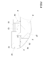
- Fig. 2 can be detected on the device 1 two each associated with the related angle 3, 3 'boom 21 and 21'.
- These booms 21 and 21 ' are compared to the respective angle 3, 3' adjustable in their position and can be applied to the door frame 27.
- the frame legs of the door frame 27 can be aligned in depth to measure or so that the door frame 2 can be set up.
- the device 1 also has height-adjustable feet 22, which are connected to the respective angles 3 and 3 'to its further support.
- the angle 3 or 3 ' can be additionally supported in their respective corner position, which can increase the stability of the device 1 when mounting the door frame 2 even further.
- the angle 3 ' has a tilting instrument 23 in the form of a dragonfly.
- the door frame 2 is possible after it has been inserted into the wall opening 7.
- angles 3, 3 ' can have raised bearing surfaces 24 for applying a tilt or angle measuring instrument.
- a spirit level can thus be applied to the device 1 without having to consider other parts of the device 1.
- the angle 3 or 3 ' designed as a crossbar.
- the side surfaces of the bar can thus form the two legs 5, 6 of the respective angle 3, 3 '.
- Fig. 5 illustrated device 29 As a second embodiment of the invention, two angles 30, 30 ', which lead parts of the teaching 9, which creates simple construction conditions.
- the linkage 34 of the doctrine 9 is non-slip connected to the angle 30.
- the angle 30, 30 ' are made adjustable in their vertical length.
- an adjusting device 35 is provided, which is lockable similarly to the teaching about fixing screws 36.
- the two parts 31 and 32 of the angle 30 can be changed in their distance.
- Fig. 2 a with the respective angle 3, 3 'connected securing band 37, 37' are removed, which can secure the device 1 in addition to the support of the angle 3. 3 '.
- the hinged over an angle between wall 8 and door frame 2 backup tape 37, 37 ' can thus reduce the risk of unwanted tilting of the device 1.
Landscapes
- Engineering & Computer Science (AREA)
- Architecture (AREA)
- Civil Engineering (AREA)
- Structural Engineering (AREA)
- Door And Window Frames Mounted To Openings (AREA)
Applications Claiming Priority (2)
| Application Number | Priority Date | Filing Date | Title |
|---|---|---|---|
| AT5532010 | 2010-09-06 | ||
| DE201010045855 DE102010045855A1 (de) | 2010-09-17 | 2010-09-17 | Vorrichtung zur Montage eines Rahmens |
Publications (3)
| Publication Number | Publication Date |
|---|---|
| EP2426292A2 true EP2426292A2 (fr) | 2012-03-07 |
| EP2426292A3 EP2426292A3 (fr) | 2014-05-07 |
| EP2426292B1 EP2426292B1 (fr) | 2016-11-23 |
Family
ID=44582570
Family Applications (1)
| Application Number | Title | Priority Date | Filing Date |
|---|---|---|---|
| EP11180294.8A Not-in-force EP2426292B1 (fr) | 2010-09-06 | 2011-09-06 | Dispositif destiné au montage d'un châssis de porte |
Country Status (1)
| Country | Link |
|---|---|
| EP (1) | EP2426292B1 (fr) |
Cited By (2)
| Publication number | Priority date | Publication date | Assignee | Title |
|---|---|---|---|---|
| CN114482812A (zh) * | 2022-01-25 | 2022-05-13 | 山东小鸭集团洗涤机械有限公司 | 一种隔离式洗脱机自动门校准装置 |
| DE102024101870A1 (de) * | 2024-01-23 | 2025-07-24 | Adolf Würth GmbH & Co. KG | Vorrichtung zum Montieren und/oder Positionieren einer Zarge und Verfahren zum Montieren und/oder Festlegen der Vorrichtung an die Zarge |
Citations (2)
| Publication number | Priority date | Publication date | Assignee | Title |
|---|---|---|---|---|
| DE3219066C2 (fr) | 1982-05-21 | 1993-03-11 | Karl 8070 Ingolstadt De Hefner | |
| DE29822526U1 (de) | 1998-12-17 | 2000-04-20 | Müller, Georg, 84149 Velden | Montagevorrichtung zum Montieren einer Zarge |
Family Cites Families (2)
| Publication number | Priority date | Publication date | Assignee | Title |
|---|---|---|---|---|
| US6237233B1 (en) * | 1999-10-13 | 2001-05-29 | Robert J. Cloutier | Door frame adjustment apparatus |
| US6981301B2 (en) * | 2004-06-08 | 2006-01-03 | Widget Tools, Llc | Device for installing a pre-hung door |
-
2011
- 2011-09-06 EP EP11180294.8A patent/EP2426292B1/fr not_active Not-in-force
Patent Citations (2)
| Publication number | Priority date | Publication date | Assignee | Title |
|---|---|---|---|---|
| DE3219066C2 (fr) | 1982-05-21 | 1993-03-11 | Karl 8070 Ingolstadt De Hefner | |
| DE29822526U1 (de) | 1998-12-17 | 2000-04-20 | Müller, Georg, 84149 Velden | Montagevorrichtung zum Montieren einer Zarge |
Cited By (3)
| Publication number | Priority date | Publication date | Assignee | Title |
|---|---|---|---|---|
| CN114482812A (zh) * | 2022-01-25 | 2022-05-13 | 山东小鸭集团洗涤机械有限公司 | 一种隔离式洗脱机自动门校准装置 |
| DE102024101870A1 (de) * | 2024-01-23 | 2025-07-24 | Adolf Würth GmbH & Co. KG | Vorrichtung zum Montieren und/oder Positionieren einer Zarge und Verfahren zum Montieren und/oder Festlegen der Vorrichtung an die Zarge |
| EP4592473A1 (fr) * | 2024-01-23 | 2025-07-30 | Stauf Design aus Holz GmbH | Dispositif de montage et/ou de positionnement d'un dormant et procédé de montage et/ou de fixation du dispositif sur le dormant |
Also Published As
| Publication number | Publication date |
|---|---|
| EP2426292B1 (fr) | 2016-11-23 |
| EP2426292A3 (fr) | 2014-05-07 |
Similar Documents
| Publication | Publication Date | Title |
|---|---|---|
| EP2002944B1 (fr) | Supports de machines | |
| EP2321081B1 (fr) | Machine-outil, en particulier scie circulaire à table | |
| EP2544573B1 (fr) | Méthode de montage d'une paroi de douche | |
| DE102016125683B3 (de) | Montagevorrichtung zum Einsetzen von Rahmenelementen in Wandöffnungen | |
| DE3219066C2 (fr) | ||
| DE20300537U1 (de) | Vorrichtung zur Befestigung von mobilen Absperreinrichtungen an Bahngleisen | |
| EP2426292B1 (fr) | Dispositif destiné au montage d'un châssis de porte | |
| EP2633963A1 (fr) | Dispositif de coupe à fil chaud | |
| AT505957B1 (de) | Spreizvorrichtung zum einbau von zargen | |
| EP0976890A2 (fr) | Dispositif de montage pour le montage d'un dormant | |
| DE102007019876B4 (de) | Vorrichtung zum Montieren und Bearbeiten von vorgefertigten Bauelementen | |
| DE4336200A1 (de) | Geländerzwinge | |
| AT516721A4 (de) | Geländer und Verfahren zur Herstellung eines Geländers | |
| DE102010060816B4 (de) | Breitenverstellbare Fußstütze für einen Rollstuhl und Faltrollstuhl hiermit | |
| DE102019126680A1 (de) | Vorrichtung und Verfahren zur Montage von Türfuttern | |
| DE29822526U1 (de) | Montagevorrichtung zum Montieren einer Zarge | |
| DE102006003171A1 (de) | Arbeitsbock, insbesondere Sägebock, und Werktischgestell | |
| DE202005003781U1 (de) | Sicherheitsvorrichtung für Fenster | |
| DE202009015280U1 (de) | Arbeits- und Montagebock | |
| DE2333926A1 (de) | Stuetze fuer rahmenfoermige teile od.dgl | |
| EP1338718A2 (fr) | Balustrade de balcon ou d'escalier avec système pour fixer un poteau, une main courante et/ou un remplissage | |
| DE10230640A1 (de) | Vorrichtung zum Befestigen eines Pfostens | |
| DE102014105647B3 (de) | Torantriebsbefestigungsvorrichtung und damit versehene Torantriebsvorrichtung | |
| EP2480736B1 (fr) | Profilé protecteur pour encadrements de fenêtre ou de porte | |
| EP2540942A2 (fr) | Agencement de ferrure réglable |
Legal Events
| Date | Code | Title | Description |
|---|---|---|---|
| AK | Designated contracting states |
Kind code of ref document: A2 Designated state(s): AL AT BE BG CH CY CZ DE DK EE ES FI FR GB GR HR HU IE IS IT LI LT LU LV MC MK MT NL NO PL PT RO RS SE SI SK SM TR |
|
| AX | Request for extension of the european patent |
Extension state: BA ME |
|
| PUAI | Public reference made under article 153(3) epc to a published international application that has entered the european phase |
Free format text: ORIGINAL CODE: 0009012 |
|
| PUAL | Search report despatched |
Free format text: ORIGINAL CODE: 0009013 |
|
| AK | Designated contracting states |
Kind code of ref document: A3 Designated state(s): AL AT BE BG CH CY CZ DE DK EE ES FI FR GB GR HR HU IE IS IT LI LT LU LV MC MK MT NL NO PL PT RO RS SE SI SK SM TR |
|
| AX | Request for extension of the european patent |
Extension state: BA ME |
|
| RIC1 | Information provided on ipc code assigned before grant |
Ipc: E04F 21/00 20060101AFI20140401BHEP |
|
| 17P | Request for examination filed |
Effective date: 20141107 |
|
| RBV | Designated contracting states (corrected) |
Designated state(s): AL AT BE BG CH CY CZ DE DK EE ES FI FR GB GR HR HU IE IS IT LI LT LU LV MC MK MT NL NO PL PT RO RS SE SI SK SM TR |
|
| GRAP | Despatch of communication of intention to grant a patent |
Free format text: ORIGINAL CODE: EPIDOSNIGR1 |
|
| INTG | Intention to grant announced |
Effective date: 20160107 |
|
| GRAS | Grant fee paid |
Free format text: ORIGINAL CODE: EPIDOSNIGR3 |
|
| GRAP | Despatch of communication of intention to grant a patent |
Free format text: ORIGINAL CODE: EPIDOSNIGR1 |
|
| INTG | Intention to grant announced |
Effective date: 20160622 |
|
| GRAA | (expected) grant |
Free format text: ORIGINAL CODE: 0009210 |
|
| AK | Designated contracting states |
Kind code of ref document: B1 Designated state(s): AL AT BE BG CH CY CZ DE DK EE ES FI FR GB GR HR HU IE IS IT LI LT LU LV MC MK MT NL NO PL PT RO RS SE SI SK SM TR |
|
| REG | Reference to a national code |
Ref country code: GB Ref legal event code: FG4D Free format text: NOT ENGLISH |
|
| REG | Reference to a national code |
Ref country code: CH Ref legal event code: EP |
|
| REG | Reference to a national code |
Ref country code: IE Ref legal event code: FG4D Free format text: LANGUAGE OF EP DOCUMENT: GERMAN |
|
| REG | Reference to a national code |
Ref country code: AT Ref legal event code: REF Ref document number: 848077 Country of ref document: AT Kind code of ref document: T Effective date: 20161215 |
|
| REG | Reference to a national code |
Ref country code: DE Ref legal event code: R096 Ref document number: 502011011185 Country of ref document: DE |
|
| PG25 | Lapsed in a contracting state [announced via postgrant information from national office to epo] |
Ref country code: LV Free format text: LAPSE BECAUSE OF FAILURE TO SUBMIT A TRANSLATION OF THE DESCRIPTION OR TO PAY THE FEE WITHIN THE PRESCRIBED TIME-LIMIT Effective date: 20161123 |
|
| REG | Reference to a national code |
Ref country code: CH Ref legal event code: NV Representative=s name: ISLER AND PEDRAZZINI AG, CH |
|
| REG | Reference to a national code |
Ref country code: LT Ref legal event code: MG4D |
|
| REG | Reference to a national code |
Ref country code: NL Ref legal event code: MP Effective date: 20161123 |
|
| PG25 | Lapsed in a contracting state [announced via postgrant information from national office to epo] |
Ref country code: NL Free format text: LAPSE BECAUSE OF FAILURE TO SUBMIT A TRANSLATION OF THE DESCRIPTION OR TO PAY THE FEE WITHIN THE PRESCRIBED TIME-LIMIT Effective date: 20161123 Ref country code: NO Free format text: LAPSE BECAUSE OF FAILURE TO SUBMIT A TRANSLATION OF THE DESCRIPTION OR TO PAY THE FEE WITHIN THE PRESCRIBED TIME-LIMIT Effective date: 20170223 Ref country code: SE Free format text: LAPSE BECAUSE OF FAILURE TO SUBMIT A TRANSLATION OF THE DESCRIPTION OR TO PAY THE FEE WITHIN THE PRESCRIBED TIME-LIMIT Effective date: 20161123 Ref country code: LT Free format text: LAPSE BECAUSE OF FAILURE TO SUBMIT A TRANSLATION OF THE DESCRIPTION OR TO PAY THE FEE WITHIN THE PRESCRIBED TIME-LIMIT Effective date: 20161123 Ref country code: GR Free format text: LAPSE BECAUSE OF FAILURE TO SUBMIT A TRANSLATION OF THE DESCRIPTION OR TO PAY THE FEE WITHIN THE PRESCRIBED TIME-LIMIT Effective date: 20170224 |
|
| PG25 | Lapsed in a contracting state [announced via postgrant information from national office to epo] |
Ref country code: PT Free format text: LAPSE BECAUSE OF FAILURE TO SUBMIT A TRANSLATION OF THE DESCRIPTION OR TO PAY THE FEE WITHIN THE PRESCRIBED TIME-LIMIT Effective date: 20170323 Ref country code: PL Free format text: LAPSE BECAUSE OF FAILURE TO SUBMIT A TRANSLATION OF THE DESCRIPTION OR TO PAY THE FEE WITHIN THE PRESCRIBED TIME-LIMIT Effective date: 20161123 Ref country code: FI Free format text: LAPSE BECAUSE OF FAILURE TO SUBMIT A TRANSLATION OF THE DESCRIPTION OR TO PAY THE FEE WITHIN THE PRESCRIBED TIME-LIMIT Effective date: 20161123 Ref country code: HR Free format text: LAPSE BECAUSE OF FAILURE TO SUBMIT A TRANSLATION OF THE DESCRIPTION OR TO PAY THE FEE WITHIN THE PRESCRIBED TIME-LIMIT Effective date: 20161123 Ref country code: ES Free format text: LAPSE BECAUSE OF FAILURE TO SUBMIT A TRANSLATION OF THE DESCRIPTION OR TO PAY THE FEE WITHIN THE PRESCRIBED TIME-LIMIT Effective date: 20161123 Ref country code: RS Free format text: LAPSE BECAUSE OF FAILURE TO SUBMIT A TRANSLATION OF THE DESCRIPTION OR TO PAY THE FEE WITHIN THE PRESCRIBED TIME-LIMIT Effective date: 20161123 |
|
| PG25 | Lapsed in a contracting state [announced via postgrant information from national office to epo] |
Ref country code: DK Free format text: LAPSE BECAUSE OF FAILURE TO SUBMIT A TRANSLATION OF THE DESCRIPTION OR TO PAY THE FEE WITHIN THE PRESCRIBED TIME-LIMIT Effective date: 20161123 Ref country code: EE Free format text: LAPSE BECAUSE OF FAILURE TO SUBMIT A TRANSLATION OF THE DESCRIPTION OR TO PAY THE FEE WITHIN THE PRESCRIBED TIME-LIMIT Effective date: 20161123 Ref country code: SK Free format text: LAPSE BECAUSE OF FAILURE TO SUBMIT A TRANSLATION OF THE DESCRIPTION OR TO PAY THE FEE WITHIN THE PRESCRIBED TIME-LIMIT Effective date: 20161123 Ref country code: RO Free format text: LAPSE BECAUSE OF FAILURE TO SUBMIT A TRANSLATION OF THE DESCRIPTION OR TO PAY THE FEE WITHIN THE PRESCRIBED TIME-LIMIT Effective date: 20161123 Ref country code: CZ Free format text: LAPSE BECAUSE OF FAILURE TO SUBMIT A TRANSLATION OF THE DESCRIPTION OR TO PAY THE FEE WITHIN THE PRESCRIBED TIME-LIMIT Effective date: 20161123 |
|
| REG | Reference to a national code |
Ref country code: DE Ref legal event code: R097 Ref document number: 502011011185 Country of ref document: DE |
|
| PG25 | Lapsed in a contracting state [announced via postgrant information from national office to epo] |
Ref country code: IT Free format text: LAPSE BECAUSE OF FAILURE TO SUBMIT A TRANSLATION OF THE DESCRIPTION OR TO PAY THE FEE WITHIN THE PRESCRIBED TIME-LIMIT Effective date: 20161123 Ref country code: BG Free format text: LAPSE BECAUSE OF FAILURE TO SUBMIT A TRANSLATION OF THE DESCRIPTION OR TO PAY THE FEE WITHIN THE PRESCRIBED TIME-LIMIT Effective date: 20170223 Ref country code: SM Free format text: LAPSE BECAUSE OF FAILURE TO SUBMIT A TRANSLATION OF THE DESCRIPTION OR TO PAY THE FEE WITHIN THE PRESCRIBED TIME-LIMIT Effective date: 20161123 |
|
| REG | Reference to a national code |
Ref country code: FR Ref legal event code: PLFP Year of fee payment: 7 |
|
| PLBE | No opposition filed within time limit |
Free format text: ORIGINAL CODE: 0009261 |
|
| STAA | Information on the status of an ep patent application or granted ep patent |
Free format text: STATUS: NO OPPOSITION FILED WITHIN TIME LIMIT |
|
| 26N | No opposition filed |
Effective date: 20170824 |
|
| PG25 | Lapsed in a contracting state [announced via postgrant information from national office to epo] |
Ref country code: SI Free format text: LAPSE BECAUSE OF FAILURE TO SUBMIT A TRANSLATION OF THE DESCRIPTION OR TO PAY THE FEE WITHIN THE PRESCRIBED TIME-LIMIT Effective date: 20161123 |
|
| PG25 | Lapsed in a contracting state [announced via postgrant information from national office to epo] |
Ref country code: MC Free format text: LAPSE BECAUSE OF FAILURE TO SUBMIT A TRANSLATION OF THE DESCRIPTION OR TO PAY THE FEE WITHIN THE PRESCRIBED TIME-LIMIT Effective date: 20161123 |
|
| REG | Reference to a national code |
Ref country code: IE Ref legal event code: MM4A |
|
| REG | Reference to a national code |
Ref country code: BE Ref legal event code: MM Effective date: 20170930 |
|
| PG25 | Lapsed in a contracting state [announced via postgrant information from national office to epo] |
Ref country code: LU Free format text: LAPSE BECAUSE OF NON-PAYMENT OF DUE FEES Effective date: 20170906 |
|
| PG25 | Lapsed in a contracting state [announced via postgrant information from national office to epo] |
Ref country code: IE Free format text: LAPSE BECAUSE OF NON-PAYMENT OF DUE FEES Effective date: 20170906 |
|
| PG25 | Lapsed in a contracting state [announced via postgrant information from national office to epo] |
Ref country code: BE Free format text: LAPSE BECAUSE OF NON-PAYMENT OF DUE FEES Effective date: 20170930 |
|
| REG | Reference to a national code |
Ref country code: FR Ref legal event code: PLFP Year of fee payment: 8 |
|
| PG25 | Lapsed in a contracting state [announced via postgrant information from national office to epo] |
Ref country code: MT Free format text: LAPSE BECAUSE OF FAILURE TO SUBMIT A TRANSLATION OF THE DESCRIPTION OR TO PAY THE FEE WITHIN THE PRESCRIBED TIME-LIMIT Effective date: 20161123 |
|
| PGFP | Annual fee paid to national office [announced via postgrant information from national office to epo] |
Ref country code: SI Payment date: 20181005 Year of fee payment: 15 |
|
| PG25 | Lapsed in a contracting state [announced via postgrant information from national office to epo] |
Ref country code: HU Free format text: LAPSE BECAUSE OF FAILURE TO SUBMIT A TRANSLATION OF THE DESCRIPTION OR TO PAY THE FEE WITHIN THE PRESCRIBED TIME-LIMIT; INVALID AB INITIO Effective date: 20110906 |
|
| PG25 | Lapsed in a contracting state [announced via postgrant information from national office to epo] |
Ref country code: CY Free format text: LAPSE BECAUSE OF NON-PAYMENT OF DUE FEES Effective date: 20161123 |
|
| PG25 | Lapsed in a contracting state [announced via postgrant information from national office to epo] |
Ref country code: MK Free format text: LAPSE BECAUSE OF FAILURE TO SUBMIT A TRANSLATION OF THE DESCRIPTION OR TO PAY THE FEE WITHIN THE PRESCRIBED TIME-LIMIT Effective date: 20161123 |
|
| PG25 | Lapsed in a contracting state [announced via postgrant information from national office to epo] |
Ref country code: TR Free format text: LAPSE BECAUSE OF FAILURE TO SUBMIT A TRANSLATION OF THE DESCRIPTION OR TO PAY THE FEE WITHIN THE PRESCRIBED TIME-LIMIT Effective date: 20161123 |
|
| PG25 | Lapsed in a contracting state [announced via postgrant information from national office to epo] |
Ref country code: AL Free format text: LAPSE BECAUSE OF FAILURE TO SUBMIT A TRANSLATION OF THE DESCRIPTION OR TO PAY THE FEE WITHIN THE PRESCRIBED TIME-LIMIT Effective date: 20161123 Ref country code: IS Free format text: LAPSE BECAUSE OF FAILURE TO SUBMIT A TRANSLATION OF THE DESCRIPTION OR TO PAY THE FEE WITHIN THE PRESCRIBED TIME-LIMIT Effective date: 20170323 |
|
| GBPC | Gb: european patent ceased through non-payment of renewal fee |
Effective date: 20190906 |
|
| PG25 | Lapsed in a contracting state [announced via postgrant information from national office to epo] |
Ref country code: GB Free format text: LAPSE BECAUSE OF NON-PAYMENT OF DUE FEES Effective date: 20190906 |
|
| PGFP | Annual fee paid to national office [announced via postgrant information from national office to epo] |
Ref country code: DE Payment date: 20200924 Year of fee payment: 10 Ref country code: FR Payment date: 20200921 Year of fee payment: 10 |
|
| PGFP | Annual fee paid to national office [announced via postgrant information from national office to epo] |
Ref country code: AT Payment date: 20200918 Year of fee payment: 10 Ref country code: CH Payment date: 20200925 Year of fee payment: 10 |
|
| REG | Reference to a national code |
Ref country code: DE Ref legal event code: R119 Ref document number: 502011011185 Country of ref document: DE |
|
| REG | Reference to a national code |
Ref country code: CH Ref legal event code: PL |
|
| REG | Reference to a national code |
Ref country code: AT Ref legal event code: MM01 Ref document number: 848077 Country of ref document: AT Kind code of ref document: T Effective date: 20210906 |
|
| PG25 | Lapsed in a contracting state [announced via postgrant information from national office to epo] |
Ref country code: FR Free format text: LAPSE BECAUSE OF NON-PAYMENT OF DUE FEES Effective date: 20210930 Ref country code: DE Free format text: LAPSE BECAUSE OF NON-PAYMENT OF DUE FEES Effective date: 20220401 |
|
| PG25 | Lapsed in a contracting state [announced via postgrant information from national office to epo] |
Ref country code: LI Free format text: LAPSE BECAUSE OF NON-PAYMENT OF DUE FEES Effective date: 20210930 Ref country code: CH Free format text: LAPSE BECAUSE OF NON-PAYMENT OF DUE FEES Effective date: 20210930 Ref country code: AT Free format text: LAPSE BECAUSE OF NON-PAYMENT OF DUE FEES Effective date: 20210906 |