EP2426360A2 - Agencement de pompes doté d'une mesure de vibrations intégrée - Google Patents
Agencement de pompes doté d'une mesure de vibrations intégrée Download PDFInfo
- Publication number
- EP2426360A2 EP2426360A2 EP11180480A EP11180480A EP2426360A2 EP 2426360 A2 EP2426360 A2 EP 2426360A2 EP 11180480 A EP11180480 A EP 11180480A EP 11180480 A EP11180480 A EP 11180480A EP 2426360 A2 EP2426360 A2 EP 2426360A2
- Authority
- EP
- European Patent Office
- Prior art keywords
- acceleration sensor
- bearing
- housing
- pump arrangement
- pump
- Prior art date
- Legal status (The legal status is an assumption and is not a legal conclusion. Google has not performed a legal analysis and makes no representation as to the accuracy of the status listed.)
- Withdrawn
Links
- 238000005259 measurement Methods 0.000 title description 12
- 230000001133 acceleration Effects 0.000 claims abstract description 61
- 238000000034 method Methods 0.000 claims abstract description 14
- 230000005540 biological transmission Effects 0.000 claims abstract description 4
- 229920003002 synthetic resin Polymers 0.000 claims abstract description 3
- 239000000057 synthetic resin Substances 0.000 claims abstract description 3
- 238000001228 spectrum Methods 0.000 claims description 25
- 239000012530 fluid Substances 0.000 claims description 8
- 230000010355 oscillation Effects 0.000 claims description 5
- 238000012545 processing Methods 0.000 claims description 5
- 230000002093 peripheral effect Effects 0.000 claims description 2
- 238000011156 evaluation Methods 0.000 abstract description 7
- 230000006399 behavior Effects 0.000 description 11
- 238000012544 monitoring process Methods 0.000 description 10
- 238000003745 diagnosis Methods 0.000 description 5
- 230000002349 favourable effect Effects 0.000 description 5
- XLYOFNOQVPJJNP-UHFFFAOYSA-N water Substances O XLYOFNOQVPJJNP-UHFFFAOYSA-N 0.000 description 4
- 230000000712 assembly Effects 0.000 description 3
- 238000000429 assembly Methods 0.000 description 3
- 238000007789 sealing Methods 0.000 description 3
- 238000005266 casting Methods 0.000 description 2
- 238000013500 data storage Methods 0.000 description 2
- 238000012423 maintenance Methods 0.000 description 2
- 229910052782 aluminium Inorganic materials 0.000 description 1
- XAGFODPZIPBFFR-UHFFFAOYSA-N aluminium Chemical compound [Al] XAGFODPZIPBFFR-UHFFFAOYSA-N 0.000 description 1
- 238000009529 body temperature measurement Methods 0.000 description 1
- 150000001875 compounds Chemical class 0.000 description 1
- 238000013461 design Methods 0.000 description 1
- 238000005553 drilling Methods 0.000 description 1
- 230000000694 effects Effects 0.000 description 1
- 230000005284 excitation Effects 0.000 description 1
- 210000004907 gland Anatomy 0.000 description 1
- 238000003780 insertion Methods 0.000 description 1
- 230000037431 insertion Effects 0.000 description 1
- 238000009434 installation Methods 0.000 description 1
- 230000010354 integration Effects 0.000 description 1
- 239000007788 liquid Substances 0.000 description 1
- 239000000463 material Substances 0.000 description 1
- 229910052751 metal Inorganic materials 0.000 description 1
- 239000002184 metal Substances 0.000 description 1
- 239000007769 metal material Substances 0.000 description 1
- 238000012806 monitoring device Methods 0.000 description 1
- 239000003129 oil well Substances 0.000 description 1
- 230000003287 optical effect Effects 0.000 description 1
- BASFCYQUMIYNBI-UHFFFAOYSA-N platinum Chemical compound [Pt] BASFCYQUMIYNBI-UHFFFAOYSA-N 0.000 description 1
- 230000008092 positive effect Effects 0.000 description 1
- 238000005096 rolling process Methods 0.000 description 1
- 230000035939 shock Effects 0.000 description 1
- 239000000126 substance Substances 0.000 description 1
- 238000012360 testing method Methods 0.000 description 1
- 239000002351 wastewater Substances 0.000 description 1
Images

Classifications
-
- F—MECHANICAL ENGINEERING; LIGHTING; HEATING; WEAPONS; BLASTING
- F04—POSITIVE - DISPLACEMENT MACHINES FOR LIQUIDS; PUMPS FOR LIQUIDS OR ELASTIC FLUIDS
- F04D—NON-POSITIVE-DISPLACEMENT PUMPS
- F04D15/00—Control, e.g. regulation, of pumps, pumping installations or systems
- F04D15/0088—Testing machines
-
- F—MECHANICAL ENGINEERING; LIGHTING; HEATING; WEAPONS; BLASTING
- F04—POSITIVE - DISPLACEMENT MACHINES FOR LIQUIDS; PUMPS FOR LIQUIDS OR ELASTIC FLUIDS
- F04D—NON-POSITIVE-DISPLACEMENT PUMPS
- F04D13/00—Pumping installations or systems
- F04D13/02—Units comprising pumps and their driving means
- F04D13/06—Units comprising pumps and their driving means the pump being electrically driven
- F04D13/08—Units comprising pumps and their driving means the pump being electrically driven for submerged use
Definitions
- the invention relates to a pump arrangement for conveying a fluid, in particular a centrifugal pump.
- a centrifugal pump lift fluids or increase their pressure or speeds. For centrifugal pumps this is done by mechanical work is transmitted by the centrifugal force and deflection of the medium in paddle wheels.
- pumped media can also be aggressive media, chemicals, sludges or viscous liquids.
- Pump assemblies of the type mentioned usually include an electric motor which is rotatably mounted in a housing of the pump assembly.
- U1 is a submersible pump for low water levels with a bottom suction known.
- the submersible pump comprises a sensor switch, which has an electrical contact above a ground contact surface, which activates a switch-on of the submersible pump when flooded by water.
- the pump unit comprises a sensor for detecting mechanical vibrations at a location of a component of the pump unit or a component mechanically connected thereto, as well as evaluation electronics for determining a vibration value and with a control unit for energizing the stator coils of the electric motor.
- a method for operating a controllable electric motor for a centrifugal pump is known. It is an electronics with a regulator and a vibration sensor provided.
- the regulator is supplied with the amplitudes of the vibration of the pump housing measured by the vibration sensor as a control input via a cable.
- the vibration sensor has two conductive metal plates, between which a piezoelectric element is arranged. One of the plates is glued directly to the front of the pump housing.
- the level monitor includes an optical sensor that measures the speed of the pump. Based on the measured speed, the pump can be switched off.
- a pump unit in the form of a vertically arranged dry runner with an electric motor drive unit, a pump unit and an interposed device known.
- the device has a lantern which encompasses mechanical connecting means for driving the pump unit by the drive unit and on which the drive unit adjoins on one end side and the pump unit on the axially opposite end side.
- On or in the lantern monitoring electronics for detecting the operating state of the pump unit is arranged.
- Various sensors are connected to the monitoring electronics.
- a vibration sensor is in mechanically fixed connection with the lantern and detects the mechanical vibrations on the pump unit.
- a system for monitoring a submersible motor pump for insertion into a wellbore of an oil well is known.
- the submersible motor pump has a rotation or angle measuring sensor, which can detect a rotational movement of the submersible pump.
- a microprocessor is provided, to which the measurement data of the sensor are forwarded.
- the sensor and the microprocessor are arranged in a meter on the submersible pump.
- the present invention is therefore based on the object to propose a pump arrangement with which the running behavior or the operating state can be monitored, so that damage to the pump assembly can be avoided and their life is extended.
- the object further consists in proposing a method for evaluating vibration data of such a pump arrangement with which damage to the pump arrangement can be detected in good time and in particular assigned to a possible cause.
- the solution consists in a pump arrangement for conveying a fluid, comprising a drive shaft, which is rotatably mounted by means of a bearing in the housing about an axis of rotation, an acceleration sensor which is fixedly connected to the housing, and an electronic unit which is connected to the acceleration sensor for data transmission is connected, wherein the acceleration sensor and the electronic unit are arranged within the housing.
- the pump arrangement is designed in the form of a submersible pump and comprises an electric motor arranged in the housing for driving the drive shaft.
- the housing is sealed to the outside, so that no fluid undesirably enters the interior of the submersible pump.
- the advantage is that the acceleration sensor can detect vibrations of the drive shaft directly inside the housing.
- the recorded shrinkage data can then be further processed in the electronics unit in order to draw conclusions about possible confounding factors.
- the running behavior of the pump assembly can be improved and damage to the pump can be detected early and avoided.
- the pump may already include an evaluation unit in the electronic unit, which records and further processes vibration data and / or calculates characteristic values from the vibration data. A separate evaluation unit outside the pump arrangement is not required.
- a preferred use of the pump assembly according to the invention is the use as a submersible pump, that is a centrifugal pump, which is immersed in the fluid to be delivered and which is usually driven by electric current.
- the use as a submersible pump is particularly favorable, because in addition to the live parts and the measuring sensors and the electronics are isolated by integration into the pump against the environment and related interference.
- a watertight and / or pressure-sealed chamber is provided within the housing, in which the acceleration sensor is arranged.
- This watertight or pressure-sealed separate chamber is enclosed by housing parts of the housing and reliably protects the components arranged therein from external influences.
- the acceleration sensor can thus provide unadulterated and accurate data over time, as it is not subject to external influences due to the arrangement in the sealed chamber.
- the acceleration sensor is in particular arranged on or in one of the housing parts surrounding the chamber and connected thereto. It is understood that not only one but also a plurality of acceleration sensors can be provided within the housing, wherein more accurate measurement data or measurement data from different parts of the pump can be detected when using multiple sensors.
- the housing comprises a bearing housing part, in which the bearing is accommodated for mounting the drive shaft, wherein the acceleration sensor is directly connected to the bearing housing part.
- the bearing housing part is designed lid-shaped and forms an inner part of the housing.
- the acceleration sensor is directly attached to the bearing housing part, that is, it is attached to a surface of the bearing housing part or inserted into the bearing housing part. Characterized in that the acceleration sensor is connected directly to the bearing housing part, the detected signal is unadulterated. In this way, a high accuracy of measurement results, which in turn has a positive effect on the further processing of the collected raw data. Possible causes for An undesirable vibration behavior can thus be precisely assigned, so that a fault diagnosis is simplified and a sudden failure of the pump is prevented.
- the storage of the drive shaft can be done by means of one, two or more bearings.
- the measurement of the acceleration signals by means of the acceleration sensor is preferably carried out on one of the bearings, but can also be carried out on several of the bearings.
- the pump arrangement preferably comprises an electric motor arranged in the housing for driving the drive shaft and an impeller which is attached to the drive shaft and serves to convey the fluid.
- the bearing housing part with a motor housing part in which the electric motor is accommodated for driving the drive shaft, fixedly connected, for example by means of screw.
- the housing has, in addition to the first bearing housing part for the first bearing and the motor housing part for the electric motor, a second bearing housing part with a second bearing.
- the drive shaft is rotatably mounted in the first bearing and the second bearing about the axis of rotation and is driven by the electric motor.
- the stator of the electric motor is mounted in the motor housing, that is supported in particular in the sense of rotation, while the inner rotor is firmly connected to the drive shaft.
- the drive shaft is passed through the second bearing and the second bearing housing and carries at its end the pump impeller.
- the sensor is preferably associated with the upper bearing housing.
- the bearing housing part, on which the sensor is provided, on its side facing away from the drive shaft can be closed by means of a cover part, wherein between the bearing housing part and the lid part, a chamber is formed.
- the bearing housing part thus forms on the one hand at least as far as possible a spatial conclusion for the housing part in which the electric motor is arranged.
- the bearing housing part together with the cover part forms a chamber which serves as a cable connection space.
- the chamber is preferably safely encapsulated against external influences, the means waterproof and / or pressure-tight.
- a seal is preferably provided between the bearing housing part and the cover part.
- the attachment of the two components together can be done for example by means of several distributed over the circumference screws.
- the acceleration sensor is arranged in said chamber.
- the acceleration sensor is designed or arranged so that it can detect with respect to the axis of rotation of the drive shaft radial and / or directed in the circumferential direction movement components.
- at least one measuring axis of the sensor is aligned radially to the axis of rotation of the drive shaft, which is the excitation axis in vibrations. In this way, a very accurate measurement of vibrations of the drive shaft is made possible.
- the acceleration sensor is arranged in a bore of the bearing housing part, in the immediate vicinity of the storage of the drive shaft is particularly favorable.
- the acceleration sensor is potted in a casting material in the bore, that is, the cavity formed between the acceleration sensor and the bore wall is filled with a filling medium, in particular with a curable synthetic resin.
- a filling medium in particular with a curable synthetic resin.
- the acceleration sensor is preferably a digital sensor. This has the advantage that a direct further processing of the detected vibration data can be performed in a processor; an analog / digital converter is not required.
- a 1D sensor is used, which can detect vibration measurements in one dimension, wherein the sensitive axis of the sensor is arranged radially to the axis of rotation of the drive shaft. For one more Of course, a more accurate measurement can also use a 2D sensor that allows measurements in two dimensions.
- the sensor is preferably arranged such that a first sensitive axis lies in a first radial direction to the axis of rotation of the drive shaft and a second sensitive axis lies in a second radial direction to the axis of rotation which is perpendicular to the first radial direction.
- the acceleration sensor preferably has one or more piezo elements.
- a piezoceramic sensor plate converts dynamic pressure fluctuations into electrical signals, which can be further processed accordingly in the electronics unit.
- a micro-electro-mechanical system MEMS
- a spring-mass system Due to the deflection during acceleration, a change in the electrical capacitance can be measured between the spring-suspended part and a fixed reference electrode. It is understood that any other acceleration sensors can be used.
- the electronics unit connected to the sensor is arranged in the chamber, which is formed between the bearing housing part and the cover part.
- the electronics unit preferably comprises a processor, to which the raw data acquired by the acceleration sensor are forwarded, wherein the processor processes the raw data.
- the processor calculates reference values, characteristic values and / or frequency spectra from the vibration data acquired by the acceleration sensor, which allow specific oscillations to be assigned to corresponding mechanical causes.
- vibrations that emanate from the impeller or hydraulics such as impeller damage, clogging, imbalances or other unfavorable operating conditions, as well as vibrations that occur due to shaft bearing damage, or vibrations of the entire pump assembly, including the connected fittings and piping.
- the electronic unit has a data memory in which the raw data detected by the acceleration sensor and / or characteristic values and evaluation data determined by the processor by further processing of the raw data can be stored.
- This embodiment with integrated processor and data memory is particularly advantageous insofar as an evaluation of the running behavior of the pump can be carried out directly in the pump assembly. This in turn allows easy monitoring, maintenance and fault diagnosis of the pump.
- an interface with which the data stored in the data memory to an external peripheral device, in particular a memory-programmed control unit (PLC), can be passed.
- PLC memory-programmed control unit
- the electronics unit preferably has a housing, which is made in particular of a metallic material, for example aluminum.
- the housing is firmly connected to the bearing housing part, for example via screw. It is particularly provided that the housing is mounted with internal electronics on an end face of the bearing housing part, and preferably directly in the area in which the acceleration sensor is connected to the bearing housing part.
- the housing has a through opening through which the acceleration sensor is led to the bearing housing part. In this way it is ensured that the acceleration sensor is directly connected to the bearing housing part, but at the same time protected by the housing of the electronic unit. From the electronics unit lead cables through the lid part to the outside of the chamber.
- the cover part has a cable bushing, which is in particular sealed or pressure-sealed.
- the pump assembly according to the invention is suitable for carrying out the method according to the invention.
- substantially the same advantages are achieved with the method for evaluating vibration data as with the pump arrangement according to the invention.
- the at least one characteristic value on the one hand and the at least one frequency spectrum on the other hand a particularly accurate analysis of the vibration behavior of the pump arrangement can take place. Both data sets are taken into account in the analysis, so that conclusions about the vibration behavior or the reasons for a specific vibration behavior of the pump assembly are made possible.
- the setting of the at least one reference value of a signal representing the oscillations of the pump arrangement is preferably carried out as part of a test run when the pump arrangement is put into operation in the respective installation situation.
- the at least one reference value is defined from the calculated frequency spectrum and / or from a vibration characteristic.
- the at least one reference value may be, for example, an average value (RMS value) or maximum value of a measured period of time.
- the reference frequency spectrum may be a data set that includes a certain number of values per unit of time.
- the vibration characteristics or frequency spectra are continuously calculated over time and compared with the stored reference values. This is preferably done in the processor of the electronic unit.
- the at least one reference value, the at least one reference frequency spectrum, the characteristic values calculated therefrom and / or the calculated frequency spectrum are stored in the data memory over time.
- the data of a certain time interval are recorded and stored.
- the data stored here can be read out at any time.
- the user can draw conclusions about the operating state of the pump assembly based on the stored data of the last time interval.
- provision is made in particular for the at least one reference value or the at least one reference frequency spectrum to be permanently stored in the data memory.
- the values or spectra calculated over time are stored only for a limited time interval. For example, it is conceivable that only the last 10 to 15 minutes of the data are stored and then overwritten again.
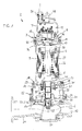
- FIGS. 1 and 2 The two FIGS. 1 and 2 will be described together below. It is shown a pump assembly 2 according to the invention, in the form of a submersible motor pump is designed.
- the pump arrangement 2 has a housing 3, an electric motor 4 accommodated in the housing 3, a drive shaft 5 driven by the electric motor 4 and an impeller 6 firmly connected to the drive shaft 5.
- the housing 3 is divided into several sections, which are subsequently connected to each other.
- the housing 3 comprises in particular a housing cover 7, a bearing housing part 8, which may also be referred to as an engine mount housing, a motor housing part 9, a lower bearing housing part 10, which may also be referred to as an engine mount housing, a second housing cover 11 and a pump housing part 12 connected thereto the impeller 6 rotates.
- the pump housing part 12 has a pressure port 21, which is connectable via a flange with a connection line, not shown. By rotating the impeller 6 fluid is conveyed from below through the suction port 31 in the direction of the discharge port 21.
- the housing cover 7 is connected via screw 13 to the motor housing part 9.
- the bearing housing part 8 is arranged, which is also connected via second screw 14 with the motor housing part 9.
- the bearing housing part 8 radially outward has a flange section which is fixed between a corresponding connection flange of the housing cover 7 and a connection flange of the motor housing part 9 by means of the screw connections 13, 14.
- the space 15 formed between the housing cover 7 and the bearing housing part 8 is sealed via a first seal 16, which is effective between the bearing housing part 8 and the housing cover 7.
- the inner space formed between the bearing housing part 8 and the motor housing part 9 is sealed to the outside via a seal 17 arranged between said components.
- the motor housing part 9 has a flange which is connected to the lower bearing housing part 10 via screws 18.
- the lower bearing housing part 10 is closed and sealed by means of the housing cover 11.
- the connection of the housing cover 11 takes place with the lower bearing housing part 10 by means of screws 20 which are screwed into a flange portion of the bearing housing part 10.
- the pump housing part 12 is attached and screwed by means of additional screws 22 which passes from above through the flange portion of the bearing housing part 10 and a flange portion of the housing cover 11 and are screwed into the pump housing part 12.
- the lower bearing housing part 10 and the housing cover 11 form a chamber 23 which is sealed by a sealing ring 24 to the outside.
- a moisture monitoring 61 is provided, with the timely recognizable when water undesirably penetrates into the chamber 23.
- a further seal 25 is effectively used, which seals these two components against each other.
- the electric motor 4 is designed in particular in the form of an asynchronous motor, which has a stator 26 which is non-rotatably connected to the motor housing part 9, and a lying within the stator 26 rotor 27 which is rotatably connected to the drive shaft 5 and drives them.
- the drive shaft 5 is rotatably supported at its overhead first end by means of a first bearing 28 in the bearing housing part 8 and by means of second bearing means 29 in the second bearing housing part 10 about the axis of rotation A.
- the first bearing 28 is designed in the form of a roller bearing, in the present case a ball bearing, wherein a bearing outer ring of the bearing 28 received in a sleeve-shaped bearing seat of the bearing housing part 8.
- the drive shaft 5 is rotatably supported by the bearing means 29 in the lower bearing housing 10.
- the drive shaft 5 is passed through the bearing housing 10 down.
- the impeller 6 is attached via a screw 32.
- the storage space of the lower bearing means 29 is closed by means of a bearing cap 33.
- the annular space formed between the bearing cap 33 and the drive shaft 5 is sealed via a first shaft seal 34 in the form of a mechanical seal.
- the annular space formed between the housing cover 11 and the drive shaft 5 is sealed by a second shaft seal 35, which is also designed in the form of a mechanical seal.
- the second bearing means 29 comprise two rolling bearings 30th
- an acceleration sensor 36 is arranged, which can detect vibrations transmitted from the bearing 28 to the bearing housing 8.
- the bearing housing 8 has a bottom 37 in which a bore 38 is provided on the side facing away from the bearing. In this case, the sensor 36 sits in the bore 38 of the bearing housing 8 a.
- the acceleration sensor 36 is designed or arranged such that it can detect effective components of movement with respect to the axis of rotation A of the drive shaft 5 at least in a radial direction, preferably in two radial and mutually orthogonal directions.
- the bore 38 is disposed in close proximity to the bearing 28, and radially adjacent to the bearing 28.
- the radial distance between the bearing outer ring and the bore 38 is smaller than the radial extent of the bearing 28.
- the axial distance between the sensor 36 and the Bearing 28 is smaller than the axial extent of the bearing 28.
- the acceleration sensor 36 can also be arranged within the outer diameter of the bearing 28. It is provided in particular that the sensor is designed in the form of a digital sensor.
- a 1D sensor can be used which can detect measurements in a radial direction to the axis of rotation A.
- a 2D sensor can also be used which allows measurements in two radial directions with respect to the axis of rotation A.
- the sensor 36 is connected via a printed circuit board 39 to an electronic unit 40.
- the electronics unit 40 comprises a preferably two-part housing 42 which is fixedly connected to the bearing housing 8, for example via screw connections, not shown here.
- electronics are arranged with a board 43, a processor 44, a voltage regulator 45, a data memory 46 and an interface converter 47.
- the processor 44 further processes the data detected by the acceleration sensor 36 and in particular calculates various vibration diagnosis values, reference values. Characteristic values and / or frequency spectra. These calculated diagnostic values and frequency spectra can then be stored in the data memory 46, as well as the raw data acquired by the acceleration sensor 36.
- the calculated values allow Associate specific vibrations of the pump assembly corresponding mechanical causes. Due to the fact that the electronic unit 40 is integrated, an evaluation of the running behavior of the pump directly in the pump arrangement 2 is possible. In this way, monitoring, maintenance and fault diagnosis of the pump are significantly improved.
- the housing 42 has a passage opening 41, through which the circuit board 39 is passed into the bore 38 of the bearing housing 8. It is envisaged that the acceleration sensor 36 together with the printed circuit board 39 and the electronics located in the housing 42 will be cast in a hardenable casting compound. In this way, the said electronic components are protected from shocks.
- the bearing housing 8 is waterproof at the top by means of a cover part 50, optionally also pressure-tight or explosion-proof, closed.
- the seal is made via a sealing ring 53 which is seated in a groove between the cover part 50 and the bearing housing 8.
- a chamber 54 is formed, which is connected via a passage opening 55 with the interior of the motor housing 9.
- the wiring not shown here is guided by the electric motor 4 through the opening 55, and the chamber 54 and corresponding cable bushings 56 in the space enclosed by the housing cover 7 15 space.
- the cover part 50 has a further cable feedthrough 49, which is watertight or pressure-sealed.
- a seal monitoring 59 is provided, which has two electrically conductive pins 60 for monitoring the moisture of the cable connection space 15.
- some control cables 62 can be seen, which serve for motor control of the electric motor 4 and are guided by the cable bushing 56 from the chamber 54 into the cable connection space 15.
- a terminal 63 for a control line which may be a cable for temperature measurement, for example, recognizable.
- a terminal board 64 is further by means Fixed screws 65 that serves to interconnect the energization of the electric motor 4 with the cable connections to the outside.
- the pump assembly 2 is closed by the housing cover 7, which encloses the cable connection space 15.
- a ring screw 48 is fixed, for example screwed, which serves for handling and transport purposes.
- the central cable glands 51 of the pump cables are provided on the housing cover 7.
- the pump arrangement according to the invention has the advantage that the acceleration sensor 36 can detect vibrations that originate from the drive shaft 5 or the bearings 28, 29 very precisely.
- the data is processed further within the pump assembly in the electronics unit 40.
- the data obtained here allow a simple way conclusions about the operating condition of the impeller 6 and the bearings 28, 29. Possible causes of an undesirable vibration behavior can thus be accurately assigned, so that a simplified diagnosis of a sudden failure of the pump 2 is prevented.
Landscapes
- Engineering & Computer Science (AREA)
- Mechanical Engineering (AREA)
- General Engineering & Computer Science (AREA)
- Structures Of Non-Positive Displacement Pumps (AREA)
- Control Of Positive-Displacement Pumps (AREA)
- Measurement Of Mechanical Vibrations Or Ultrasonic Waves (AREA)
- Details And Applications Of Rotary Liquid Pumps (AREA)
Applications Claiming Priority (1)
| Application Number | Priority Date | Filing Date | Title |
|---|---|---|---|
| DE102010037379.6A DE102010037379B4 (de) | 2010-09-07 | 2010-09-07 | Pumpenanordnung mit integrierter Vibrationsmessung |
Publications (2)
| Publication Number | Publication Date |
|---|---|
| EP2426360A2 true EP2426360A2 (fr) | 2012-03-07 |
| EP2426360A3 EP2426360A3 (fr) | 2014-09-03 |
Family
ID=44677648
Family Applications (1)
| Application Number | Title | Priority Date | Filing Date |
|---|---|---|---|
| EP11180480.3A Withdrawn EP2426360A3 (fr) | 2010-09-07 | 2011-09-07 | Agencement de pompes doté d'une mesure de vibrations intégrée |
Country Status (2)
| Country | Link |
|---|---|
| EP (1) | EP2426360A3 (fr) |
| DE (1) | DE102010037379B4 (fr) |
Cited By (7)
| Publication number | Priority date | Publication date | Assignee | Title |
|---|---|---|---|---|
| WO2018122596A1 (fr) * | 2016-12-28 | 2018-07-05 | Zolotukhin Mikhail Aleksandrovich | Pompe centrifuge suspendue verticale |
| EP3546760A1 (fr) | 2018-03-26 | 2019-10-02 | Xylem Europe GmbH | Machine électrique submersible |
| WO2019193069A1 (fr) * | 2018-04-06 | 2019-10-10 | Ksb Sas | Groupe motopompe intégré |
| CN110808570A (zh) * | 2018-08-06 | 2020-02-18 | 克利万工业-电子有限公司 | 用于废水应用和/或供水的泵 |
| CN111237209A (zh) * | 2020-02-17 | 2020-06-05 | 苏州欣皓信息技术有限公司 | 水泵转轮稳定性监测方法、装置、电子设备和存储介质 |
| RU2736677C1 (ru) * | 2019-09-06 | 2020-11-19 | Александр Николаевич Золотухин | Центробежный вертикальный насос |
| CN112290717A (zh) * | 2020-10-23 | 2021-01-29 | 湖南耐普泵业股份有限公司 | 一种具有绝缘接线板结构的永磁潜液泵 |
Families Citing this family (4)
| Publication number | Priority date | Publication date | Assignee | Title |
|---|---|---|---|---|
| DE102014208297B4 (de) | 2014-05-02 | 2019-10-31 | Homa Pumpenfabrik Gmbh | Pumpenanordnung |
| DE102023102135A1 (de) * | 2023-01-30 | 2024-08-01 | Kriwan Industrie-Elektronik Gmbh | Elektrische Maschine mit Vibrationssensor |
| DE102024000136A1 (de) | 2023-02-01 | 2024-08-01 | Sew-Eurodrive Gmbh & Co Kg | Getriebe mit Gehäuseteil |
| DE202023104808U1 (de) * | 2023-08-24 | 2024-11-26 | Paul Müller GmbH & Co. KG Unternehmensbeteiligungen | Einheit zur Datenerfassung und -verarbeitung für einen Elektromotor einer Maschine, Elektromotor und Maschine hiermit |
Citations (6)
| Publication number | Priority date | Publication date | Assignee | Title |
|---|---|---|---|---|
| DE19617570C1 (de) | 1996-05-02 | 1997-12-11 | Hanning & Kahl Gmbh & Co | Tauchpumpe |
| DE19956768A1 (de) | 1999-11-25 | 2001-05-31 | Wilo Gmbh | Pumpe mit Vibrationssensor |
| DE202004009580U1 (de) | 2004-06-17 | 2004-09-02 | Hoffmann Maschinenbau Gmbh | Tauchpumpe für geringe Wasserstände |
| GB2450157A (en) | 2007-06-15 | 2008-12-17 | Baker Hughes Inc | System For Monitoring An Electrical Submersible Pump |
| DE102008038661A1 (de) | 2008-08-12 | 2010-02-18 | Wilo Se | Geräuschminimierung von elektromotorisch betriebenen Pumpen |
| DE102009005154A1 (de) | 2009-01-15 | 2010-07-22 | Wilo Se | Vorrichtung zur Verbindung einer elektromotorischen Antriebseinheit mit einer Pumpeneinheit |
Family Cites Families (6)
| Publication number | Priority date | Publication date | Assignee | Title |
|---|---|---|---|---|
| CA2230691C (fr) | 1995-08-30 | 2004-03-30 | Baker Hughes Incorporated | Pompe electrique submersible amelioree et procedes pour une meilleure utilisation de pompes electriques submersibles dans la completion et l'exploitation des puits de forage |
| JP3906507B2 (ja) * | 1997-01-20 | 2007-04-18 | 株式会社日立プラントテクノロジー | 液化ガス用ポンプ装置 |
| US5904621A (en) | 1997-06-25 | 1999-05-18 | Tiger Electronics, Ltd. | Electronic game with infrared emitter and sensor |
| JP3657166B2 (ja) * | 2000-02-23 | 2005-06-08 | 日本特殊陶業株式会社 | 圧電ノックセンサ |
| US6566774B2 (en) | 2001-03-09 | 2003-05-20 | Baker Hughes Incorporated | Vibration damping system for ESP motor |
| US7686074B2 (en) | 2007-02-20 | 2010-03-30 | Baker Hughes Incorporated | Apparatus and method for active circuit protection of downhole electrical submersible pump monitoring gauges |
-
2010
- 2010-09-07 DE DE102010037379.6A patent/DE102010037379B4/de active Active
-
2011
- 2011-09-07 EP EP11180480.3A patent/EP2426360A3/fr not_active Withdrawn
Patent Citations (6)
| Publication number | Priority date | Publication date | Assignee | Title |
|---|---|---|---|---|
| DE19617570C1 (de) | 1996-05-02 | 1997-12-11 | Hanning & Kahl Gmbh & Co | Tauchpumpe |
| DE19956768A1 (de) | 1999-11-25 | 2001-05-31 | Wilo Gmbh | Pumpe mit Vibrationssensor |
| DE202004009580U1 (de) | 2004-06-17 | 2004-09-02 | Hoffmann Maschinenbau Gmbh | Tauchpumpe für geringe Wasserstände |
| GB2450157A (en) | 2007-06-15 | 2008-12-17 | Baker Hughes Inc | System For Monitoring An Electrical Submersible Pump |
| DE102008038661A1 (de) | 2008-08-12 | 2010-02-18 | Wilo Se | Geräuschminimierung von elektromotorisch betriebenen Pumpen |
| DE102009005154A1 (de) | 2009-01-15 | 2010-07-22 | Wilo Se | Vorrichtung zur Verbindung einer elektromotorischen Antriebseinheit mit einer Pumpeneinheit |
Cited By (14)
| Publication number | Priority date | Publication date | Assignee | Title |
|---|---|---|---|---|
| WO2018122596A1 (fr) * | 2016-12-28 | 2018-07-05 | Zolotukhin Mikhail Aleksandrovich | Pompe centrifuge suspendue verticale |
| CN111902635A (zh) * | 2018-03-26 | 2020-11-06 | 赛莱默欧洲有限公司 | 潜水电机 |
| EP3546760A1 (fr) | 2018-03-26 | 2019-10-02 | Xylem Europe GmbH | Machine électrique submersible |
| WO2019185469A1 (fr) | 2018-03-26 | 2019-10-03 | Xylem Europe Gmbh | Machine électrique submersible |
| US12078177B2 (en) * | 2018-03-26 | 2024-09-03 | Xylem Europe Gmbh | Submersible electric machine |
| WO2019193069A1 (fr) * | 2018-04-06 | 2019-10-10 | Ksb Sas | Groupe motopompe intégré |
| CN112041564A (zh) * | 2018-04-06 | 2020-12-04 | Ksb有限公司 | 一体化马达泵单元 |
| AU2019247614B2 (en) * | 2018-04-06 | 2024-08-22 | Ksb Sas | Integrated motor-pump unit |
| CN110808570A (zh) * | 2018-08-06 | 2020-02-18 | 克利万工业-电子有限公司 | 用于废水应用和/或供水的泵 |
| RU2736677C1 (ru) * | 2019-09-06 | 2020-11-19 | Александр Николаевич Золотухин | Центробежный вертикальный насос |
| CN111237209A (zh) * | 2020-02-17 | 2020-06-05 | 苏州欣皓信息技术有限公司 | 水泵转轮稳定性监测方法、装置、电子设备和存储介质 |
| CN111237209B (zh) * | 2020-02-17 | 2021-08-03 | 苏州欣皓信息技术有限公司 | 水泵转轮稳定性监测方法、装置、电子设备和存储介质 |
| CN112290717A (zh) * | 2020-10-23 | 2021-01-29 | 湖南耐普泵业股份有限公司 | 一种具有绝缘接线板结构的永磁潜液泵 |
| CN112290717B (zh) * | 2020-10-23 | 2023-03-31 | 湖南耐普泵业股份有限公司 | 一种具有绝缘接线板结构的永磁潜液泵 |
Also Published As
| Publication number | Publication date |
|---|---|
| DE102010037379B4 (de) | 2021-09-23 |
| EP2426360A3 (fr) | 2014-09-03 |
| DE102010037379A1 (de) | 2012-03-08 |
Similar Documents
| Publication | Publication Date | Title |
|---|---|---|
| EP2426360A2 (fr) | Agencement de pompes doté d'une mesure de vibrations intégrée | |
| DE112016001510B4 (de) | Motor und elektrische Servolenkvorrichtung | |
| EP2972431B1 (fr) | Moteur électrique avec surveillance fonctionnelle des paliers de moteur | |
| EP2072829B1 (fr) | Pompe submersible | |
| EP3138791B1 (fr) | Moteur a tambour et cartouche de capteur pour un moteur a tambour | |
| DE112015004207B4 (de) | Sensorikeinheit zur Bestimmung einer Rotorlage eines Elektromotors und ein Elektromotor, vorzugsweise für einen Kupplungsaktor eines Kupplungsbetätigungssystems eines Kraftfahrzeuges | |
| DE10163321C1 (de) | Spalttopfmotor | |
| WO2010081694A2 (fr) | Dispositif destiné à relier une unité d'entraînement à moteur électrique avec une unité de pompe | |
| EP0280892B1 (fr) | Pompe à vide avec dispositif de comptage des tours | |
| DE102020203266A1 (de) | Sensoranordnung und Motor | |
| DE102021201358A1 (de) | Integrierter Achsantrieb und Kraftfahrzeug | |
| DE69718889T2 (de) | Diagnoseverfahren und -Gerät für Vakuumpumpen | |
| EP1901040A2 (fr) | Capteur d'angle de rotation sans contact | |
| EP3619445B1 (fr) | Procédé pour faire fonctionner un arrangement actionneur pour un système d'actionnement d'embrayage et arrangement actionneur | |
| DE112017004013B4 (de) | Antriebsvorrichtung | |
| DE9415078U1 (de) | Feuchtigkeitsdicht geschlossenes Motor-Pumpen-Aggregat, insbesondere für eine Kraftfahrzeug-Antiblockier-Bremsvorrichtung | |
| DE10221843A1 (de) | Elektromotor zur Verwendung als Pumpenmotor und Pumpe | |
| EP2795768B1 (fr) | Entraînement comprenant un motoréducteur | |
| EP1617212B1 (fr) | Capteur capacitif pour détecter de l'eau dans l'huile | |
| DE202013006615U1 (de) | Elektrische Maschine | |
| DE102004047637B4 (de) | Elektrisch betriebene Pumpe mit Außenrotor | |
| DE102013223177B4 (de) | Gezeitenströmungskraftanlage | |
| EP1561118B1 (fr) | Systeme pour detecter le mouvement de rotation d'un arbre | |
| DE102007040563B4 (de) | Rotationsviskosimeter | |
| EP3980741B1 (fr) | Détection de dommages au moyen d'un détecteur d'odeur |
Legal Events
| Date | Code | Title | Description |
|---|---|---|---|
| AK | Designated contracting states |
Kind code of ref document: A2 Designated state(s): AL AT BE BG CH CY CZ DE DK EE ES FI FR GB GR HR HU IE IS IT LI LT LU LV MC MK MT NL NO PL PT RO RS SE SI SK SM TR |
|
| AX | Request for extension of the european patent |
Extension state: BA ME |
|
| PUAI | Public reference made under article 153(3) epc to a published international application that has entered the european phase |
Free format text: ORIGINAL CODE: 0009012 |
|
| PUAL | Search report despatched |
Free format text: ORIGINAL CODE: 0009013 |
|
| AK | Designated contracting states |
Kind code of ref document: A3 Designated state(s): AL AT BE BG CH CY CZ DE DK EE ES FI FR GB GR HR HU IE IS IT LI LT LU LV MC MK MT NL NO PL PT RO RS SE SI SK SM TR |
|
| AX | Request for extension of the european patent |
Extension state: BA ME |
|
| RIC1 | Information provided on ipc code assigned before grant |
Ipc: F04D 13/08 20060101ALI20140728BHEP Ipc: F04D 15/00 20060101AFI20140728BHEP |
|
| 17P | Request for examination filed |
Effective date: 20150303 |
|
| RBV | Designated contracting states (corrected) |
Designated state(s): AL AT BE BG CH CY CZ DE DK EE ES FI FR GB GR HR HU IE IS IT LI LT LU LV MC MK MT NL NO PL PT RO RS SE SI SK SM TR |
|
| 17Q | First examination report despatched |
Effective date: 20160726 |
|
| STAA | Information on the status of an ep patent application or granted ep patent |
Free format text: STATUS: EXAMINATION IS IN PROGRESS |
|
| STAA | Information on the status of an ep patent application or granted ep patent |
Free format text: STATUS: THE APPLICATION IS DEEMED TO BE WITHDRAWN |
|
| 18D | Application deemed to be withdrawn |
Effective date: 20171018 |