EP2426426A1 - Ventilateur échangeur de chaleur - Google Patents
Ventilateur échangeur de chaleur Download PDFInfo
- Publication number
- EP2426426A1 EP2426426A1 EP09843977A EP09843977A EP2426426A1 EP 2426426 A1 EP2426426 A1 EP 2426426A1 EP 09843977 A EP09843977 A EP 09843977A EP 09843977 A EP09843977 A EP 09843977A EP 2426426 A1 EP2426426 A1 EP 2426426A1
- Authority
- EP
- European Patent Office
- Prior art keywords
- casing
- fan
- air
- exhaust
- air supply
- Prior art date
- Legal status (The legal status is an assumption and is not a legal conclusion. Google has not performed a legal analysis and makes no representation as to the accuracy of the status listed.)
- Granted
Links
Images





Classifications
-
- F—MECHANICAL ENGINEERING; LIGHTING; HEATING; WEAPONS; BLASTING
- F24—HEATING; RANGES; VENTILATING
- F24F—AIR-CONDITIONING; AIR-HUMIDIFICATION; VENTILATION; USE OF AIR CURRENTS FOR SCREENING
- F24F12/00—Use of energy recovery systems in air conditioning, ventilation or screening
- F24F12/001—Use of energy recovery systems in air conditioning, ventilation or screening with heat-exchange between supplied and exhausted air
- F24F12/006—Use of energy recovery systems in air conditioning, ventilation or screening with heat-exchange between supplied and exhausted air using an air-to-air heat exchanger
-
- F—MECHANICAL ENGINEERING; LIGHTING; HEATING; WEAPONS; BLASTING
- F24—HEATING; RANGES; VENTILATING
- F24F—AIR-CONDITIONING; AIR-HUMIDIFICATION; VENTILATION; USE OF AIR CURRENTS FOR SCREENING
- F24F7/00—Ventilation
- F24F7/04—Ventilation with ducting systems, e.g. by double walls; with natural circulation
- F24F7/06—Ventilation with ducting systems, e.g. by double walls; with natural circulation with forced air circulation, e.g. by fan positioning of a ventilator in or against a conduit
- F24F7/08—Ventilation with ducting systems, e.g. by double walls; with natural circulation with forced air circulation, e.g. by fan positioning of a ventilator in or against a conduit with separate ducts for supplied and exhausted air with provisions for reversal of the input and output systems
-
- F—MECHANICAL ENGINEERING; LIGHTING; HEATING; WEAPONS; BLASTING
- F24—HEATING; RANGES; VENTILATING
- F24F—AIR-CONDITIONING; AIR-HUMIDIFICATION; VENTILATION; USE OF AIR CURRENTS FOR SCREENING
- F24F13/00—Details common to, or for air-conditioning, air-humidification, ventilation or use of air currents for screening
- F24F13/20—Casings or covers
-
- F—MECHANICAL ENGINEERING; LIGHTING; HEATING; WEAPONS; BLASTING
- F24—HEATING; RANGES; VENTILATING
- F24F—AIR-CONDITIONING; AIR-HUMIDIFICATION; VENTILATION; USE OF AIR CURRENTS FOR SCREENING
- F24F13/00—Details common to, or for air-conditioning, air-humidification, ventilation or use of air currents for screening
- F24F13/20—Casings or covers
- F24F2013/205—Mounting a ventilator fan therein
-
- Y—GENERAL TAGGING OF NEW TECHNOLOGICAL DEVELOPMENTS; GENERAL TAGGING OF CROSS-SECTIONAL TECHNOLOGIES SPANNING OVER SEVERAL SECTIONS OF THE IPC; TECHNICAL SUBJECTS COVERED BY FORMER USPC CROSS-REFERENCE ART COLLECTIONS [XRACs] AND DIGESTS
- Y02—TECHNOLOGIES OR APPLICATIONS FOR MITIGATION OR ADAPTATION AGAINST CLIMATE CHANGE
- Y02B—CLIMATE CHANGE MITIGATION TECHNOLOGIES RELATED TO BUILDINGS, e.g. HOUSING, HOUSE APPLIANCES OR RELATED END-USER APPLICATIONS
- Y02B30/00—Energy efficient heating, ventilation or air conditioning [HVAC]
- Y02B30/56—Heat recovery units
Definitions
- the present invention relates to a heat exchanging ventilator in which heat exchange is performed between air supply and exhaust along with air ventilation by means of air supply and exhaust.
- a heat exchanging ventilator having such a structure that an exhaust air path for exhausting indoor air to outside of a room and a supply air path for supplying outdoor air to the room are formed in a box-like main body casing, an exhaust fan is provided in the exhaust air path, an air supply fan is provided in the supply air path, and a heat exchanger is provided at a crossing between the exhaust air path and the supply air path has been known.
- a heat exchanging ventilator thermal energy is exchanged between air A outside the room and air B inside the room without being mixed with each other (see, for example, Patent Literature 1).
- Patent Literature 1 Japanese Patent Application Laid-open No. 2003-074936
- the heat exchanging ventilator needs to ensure airtightness so that air in the supply air path and air in the exhaust air path are not mixed, in order to supply outdoor fresh air to the room and exhaust indoor foul air to outside.
- airtightness is not sufficiently ensured, an effective ventilation rate decreases due to air leakage in the product enclosure, and reliable ventilation cannot be performed.
- an airtight structure of the exhaust air path and the supply air path is respectively provided on the side of a casing for the air supply and exhaust fans with an air inlet provided therein.
- a fan structure of a conventional ventilation fan uses a separate part for holding a heat exchanger so that replacement of parts becomes possible only by partially detaching/attaching a fan structural part from/to a product (when a structure for holding the heat exchanger is provided in the conventional fan structure, the heat exchanger may need to be detached as well at the time of replacing the maintenance parts such as the motor). Therefore, there is a problem that the number of parts of the entire product increases, thereby causing a cost increase. Further, an increase in the number of parts causes an increase of joint parts, thereby causing a problem of airtightness.
- a heat exchanging ventilator that can reduce product cost by reducing the number of parts, has excellent airtightness, excellent workability for replacing maintenance parts such as a motor, and excellent maintainability has been conventionally desired.
- the present invention has been achieved to solve the above problems, and an object of the present invention is to provide a heat exchanging ventilator that can improve airtightness and maintainability and can reduce the number of parts.
- a heat exchanging ventilator including an exhaust air path for exhausting indoor air to outside of a room and a supply air path for supplying outdoor air to the room, which are formed in a box-like main body casing, an exhaust fan provided in the exhaust air path, an air supply fan provided in the supply air path, and a heat exchanger provided at a crossing between the exhaust air path and the supply air path to perform heat exchange, wherein the air supply fan and the exhaust fan respectively have a motor built therein, an outer shell thereof being covered with a casing having the same shape, and are arranged in such a manner that rotation shafts of respective motors are parallel to each other and face opposite directions, and a part of an outer circumference of the casings respectively forms the exhaust air path and the supply air path, the casing for the exhaust fan and the casing for the air supply fan are respectively divided into a first casing and a second casing in a first direction (a direction of the rotation shaft) on
- the number of parts can be reduced, and particularly the number of molds for molding a casing can be reduced, thereby enabling to achieve cost reduction. Airtightness can be ensured and the number of parts can be reduced, without using any packing material in portions constituting an air supply fan, an exhaust fan, and an air path between the air supply fan and the exhaust fan. At the time of replacing the maintenance parts such as a motor, because replacement work can be performed without detaching the packing material, workability is improved.
- FIG. 1 is a plan view for explaining an air flow and a distribution channel in a heat exchanging ventilator.
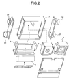
- FIG. 2 is an exploded perspective view for explaining an internal structure of the heat exchanging ventilator.
- FIG. 2 explains a function and an outline of a configuration of the heat exchanging ventilator and depicts a conventional heat exchanging ventilator described in Patent Literature 1, for example.
- the heat exchanging ventilator according to the present invention has a different structure of a casing for an air supply fan 3 and an exhaust fan 4, and a different support structure of a heat exchanger 2 including a heat-exchanger fixing part 5.
- the structure of other parts is substantially the same as that of the heat exchanging ventilator shown in FIG. 2 .
- an arrow A-A' indicates a flow of supply air or a supply air path
- an arrow B-B' indicates a flow of exhaust air or an exhaust air path.
- the heat exchanging ventilator includes an exhaust air path for exhausting indoor air to outside of the room and a supply air path for supplying outdoor air to the room formed in a box-like main body casing 1, an exhaust fan 4 provided in the exhaust air path, the air supply fan 3 provided in the supply air path, and a heat exchanger 2 provided at a crossing between the exhaust air path and the supply air path to perform heat exchange.
- Outer shells of the air supply fan 3 and the exhaust fan 4 are covered with a casing, with a motor respectively incorporated therein.
- the air supply fan 3 and the exhaust fan 4 are arranged in parallel in the main body casing 1 so that rotation shafts of the respective motors are parallel to each other and directed to opposite directions.
- Outer peripheries of the air supply fan 3 and the exhaust fan 4 constitute the supply air path and the exhaust air path. Therefore, the casing for the air supply fan 3 and the casing for the exhaust fan 4 are connected airtightly with each other.
- the sides of the casing for the air supply fan 3 and the casing for the exhaust fan 4 have been attached tightly to each other to maintain airtightness.
- the heat exchanger 2 is fixed to the main body casing 1 by the heat-exchanger fixing part 5 having a large size and a complicated structure shown in FIG. 2 .
- FIG. 3 is an exploded perspective view of the air supply fan 3 in the heat exchanging ventilator according to an embodiment of the present invention. Constituent parts and an internal structure of the air supply fan 3 are explained with reference to FIG. 3 .
- a motor casing 301 of the air supply fan 3 and a motor casing 401 of the exhaust fan 4 have the same shape.
- the constituent parts and the internal structures of the air supply fan 3 and the exhaust fan 4 including these motor casings 301 and 401 are the same. That is, the constituent parts and the internal structure of the air supply fan 3 are explained here; however, the exhaust fan 4 has the same configuration.
- the air supply fan 3 (the exhaust fan 4) is a socalled Sirocco fan having a cylindrical blade 309 of a multiblade fan on a rotation shaft of a motor 305.
- a motor mounting plate 304 is fixed to the motor casing 301 by a screw 303.
- the motor 305 is inserted from a central hole of the motor casing 301 and fastened to the motor mounting plate 304 by a screw 306.
- the blade 309 is inserted into the rotation shaft of the motor 305 via a washer 308 and fixed by a locknut 311 via a spring washer 310.
- the motor casing 301 includes a motor positioning ribs 301c, 301d, 301e, and 301f ( FIG. 9 ). These motor positioning ribs 301c, 301d, 301e, and 301f are provided at four positions with equal distance from the center of the fan, and are designed with a size such that there is no interference even if a diameter of a motor mounting surface is manufactured with a maximum tolerance.
- the motor casing 401 for the exhaust fan 4 has the same configuration.
- the casing for the air supply fan 3 includes the motor casing 301 and an suction casing 302 halved in a direction of the rotation shaft of the motor.
- the casing for the exhaust fan 4 includes the motor casing 401 and a suction casing 402 halved in the direction of the rotation shaft of the motor.
- the air supply fan 3 and the exhaust fan 4 are arranged in parallel in the main body casing 1 so that the rotation shafts of the respective motors are parallel to each other and directed to opposite directions, as in the conventional one shown in FIG. 2 .
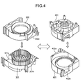
- FIG. 4 is a perspective view of details of the respectively divided casings of the air supply fan 3 and of the exhaust fan 4 according to the embodiment of the present invention.
- the casing for the air supply fan 3 includes the motor casing 301 and the suction casing 302 halved in the direction of the rotation shaft on a division surface orthogonal to the rotation shaft of the motor (not shown).
- the casing for the exhaust fan 4 also includes the motor casing 401 and the suction casing 402 halved in the direction of the rotation shaft on a surface orthogonal to the rotation shaft of the motor (not shown).
- the motor casing for the air supply fan 3 (hereinafter, “air-supply motor casing") 301 and the motor casing for the exhaust fan 4 (hereinafter, “exhaust motor casing”) 401 have the same shape.
- the suction casing for the air supply fan 3 (hereinafter, “air-supply suction casing") 302 and the suction casing for the exhaust fan 4 (hereinafter, “exhaust suction casing”) 402 have the same shape.
- FIG. 5 is a side sectional view of the motor shaft of the heat exchanging ventilator according to the embodiment of the present invention.
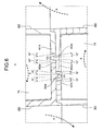
- FIG. 6 is an enlarged view of a part C in FIG. 5 .
- a position relation between the air supply fan 3 and the exhaust fan 4 in an incorporation completion state is explained with reference to FIG. 5 .
- the air supply fan 3 and the exhaust fan 4 are arranged in the main body casing 1 so that the rotation shafts of the respective motors are parallel to each other and directed to opposite directions.
- the air supply fan 3 and the exhaust fan 4 are arranged so that the division surfaces of the respective casings agree with the center of the main body casing 1 in a thickness direction (the respective casings of the air supply fan 3 and the exhaust fan 4 are divided in a central part of the main body casing 1 in the thickness direction).
- a female faucet joint structure is formed, in which a slope face that narrows a hole diameter inward is formed over the whole circumference on an inner surface of a divided opening edge of the air-supply motor casing 301.
- a male faucet joint structure is formed, in which a slope face that narrows an outer diameter toward an end is formed over the whole circumference on an outer surface of a divided opening edge of the air-supply suction casing 302.
- the both casings are combined with the respective faucet joint structures being faucet-jointed. The same thing applies to the divided opening edge between the exhaust motor casing 401 and the exhaust suction casing 402.
- the air supply fan 3 and the exhaust fan 4 installed in parallel in the main body casing 1 form the supply air path and the exhaust air path in the main body casing 1 by halving the space in the main body casing 1 (in FIG. 5 , a supply air path TA is formed in an upper part in FIG. 5 and an exhaust air path TB is formed in a lower part in FIG. 5 ).
- a supply air path TA is formed in an upper part in FIG. 5
- an exhaust air path TB is formed in a lower part in FIG. 5 .
- the air B inside the room passes through the exhaust air path TB, is sucked by the exhaust fan 4, and is exhausted to outside from the exhaust outlet 24.
- the air A outside the room passes through the supply air path TA, is sucked by the air supply fan 3, and is supplied into the room from the supply air outlet 22.
- the air-supply suction casing 302 and the exhaust motor casing 401 are fixed to the main body casing by screws. At this time, the air-supply suction casing 302 and the exhaust motor casing 401 are fixed at such positions that a predetermined clearance (gap) is formed between the adjacent casings 302 and 401.
- the air-supply motor casing 301 is also fixed to the air-supply suction casing 302 by screws.
- the exhaust suction casing 402 is fixed to the exhaust motor casing 401. Because the respective casings are fixed in this manner, the clearance between the air-supply motor casing 301 and the exhaust suction casing 402 has the same size as the clearance between the air-supply suction casing 302 and the exhaust motor casing 401.
- FIG. 7 is a perspective view of the suction casings of the air supply fan and the exhaust fan as viewed from inside of the casing.
- FIG. 8 is a perspective view of the suction casings of the air supply fan and the exhaust fan as viewed from outside of the casing.
- FIG. 9 is a perspective view of the motor casings of the air supply fan and the exhaust fan as viewed from inside of the casing.
- FIG. 10 is a perspective view of the motor casings of the air supply fan and the exhaust fan as viewed from outside of the casing.
- FIGS. 5 to 10 depict projections provided on the respective casings and a situation in which the projections superpose over each other.
- a projection 302a extending outward from the divided opening edge formed on a cut surface cut by division along the division surface is provided on the air-supply suction casing 302 on a side opposite to a supply opening 302e ( FIGS. 7 and 8 ).
- a projection 301h extending outward from the divided opening edge along the division surface is provided on the air-supply motor casing 301 on a side opposite to a supply opening 301g ( FIG. 9 ).
- the projections 302a and 301h are superposed over each other with principal surfaces opposite to each other in an axial direction of the rotation shaft of the motor (referred to as a first direction) in surface contact (surface-to-surface contact) with each other ( FIG. 6 ).
- a projection 402a extending outward from the divided opening edge along the division surface is provided on the exhaust suction casing 402 ( FIGS. 7 and 8 ).
- a projection 401h extending outward from the divided opening edge along the division surface is also provided on the exhaust motor casing 401 ( FIG. 9 ).
- the projections 402a and 401h are superposed over each other with principal surfaces opposite to each other in the first direction in surface contact (surface-to-surface contact) with each other ( FIG. 6 ).
- the projections 302a and 301h, and the projections 402a and 401h respectively extend in a direction vertical to the page in FIGS. 5 and 6 at the ends of the casings 302, 301, 402, and 401.
- the projection 302a provided on the air-supply suction casing 302 is wider than the projection 301h provided on the air-supply motor casing 301 and projects long from the divided opening edge. That is, the projection 302a extends and protrudes further outward with respect to the projection 301h ( FIG. 6 ). Likewise, the projection 302a extends and protrudes further outward with respect to the projection 301h ( FIG. 6 ).
- the projections 302a and 402a extending and protruding outward are superposed over each other with principal surfaces opposite to each other in the first direction in surface contact (surface-to-surface contact) with each other, in a portion extending and protruding outward ( FIG. 6 ).
- the space in the main body casing 1 separated by the projections 302a and 402a becomes the supply air path TA and the exhaust air path TB.
- the air supply fan 3 and the exhaust fan 4 because the supply air path TA and the exhaust air path TB are separated by the projections 302a and 402a in surface contact (surface-to-surface contact) with each other of the respective casings, airtightness is reliably maintained without any packing material.
- the projection 301h provided on the air-supply motor casing 301 and the projection 402a provided on the exhaust suction casing 402 abut against each other with a first clearance (gap) 101.
- a protrusion 302b provided in an extended condition on the principal surface of the projection 302a is fitted to the first clearance (gap) 101.
- the projection 401h provided on the exhaust motor casing 401 and the projection 302a provided on the air-supply suction casing 302 abut against each other with a second clearance (gap) 102, and a protrusion 402b provided in an extended condition on the principal surface of the projection 402a is fitted to the second clearance (gap) 102.
- the first clearance (gap) 101, the second clearance (gap) 102, and the protrusions 302b and 402b extend in the direction vertical to the page in FIGS. 5 and 6 at the ends of the casings 302, 301, 402, and 401 as in the projections 302a, 301h, 402a, and 401h. According to this configuration, airtightness between the supply air path TA and the exhaust air path TB is maintained more reliably.
- the first clearance (gap) 101 is designed with a size relation such that the protrusion 402b of the exhaust suction casing 402 fitted thereto does not interfere with the first clearance, even if there are molding variations of the air-supply suction casing 302 and the exhaust motor casing 401, and assembly variations of the air-supply suction casing 302 and the exhaust motor casing 401 with the body.
- the second clearance (gap) 102 is designed with a size relation such that the protrusion 302b of the air-supply suction casing 302 fitted thereto does not interfere with the second clearance, even if there are molding variations of the exhaust suction casing 402 and the air-supply motor casing 301, assembly variations of the exhaust suction casing 402 with the exhaust motor casing 401, and assembly variations of the air-supply motor casing 301 with the air-supply suction casing 302.
- the fan is assembled in a state with the main body casing 1 vertically inverted.
- the air-supply suction casing 302 and the exhaust motor casing 401 are assembled to the main body casing 1.
- An assembling order of the air-supply suction casing 302 and the exhaust motor casing 401 is arbitrary.
- the air-supply motor casing 301 and the exhaust suction casing 402 are assembled next.
- An assembling order of the air-supply motor casing 301 and the exhaust suction casing 402 is arbitrary.
- the projection 302a of the air-supply suction casing 302 and the projection 402a of the exhaust suction casing 402 are in surface-to-surface contact with each other on the division surface of the fan.
- the protrusion 302b of the air-supply suction casing 302 is explained with reference to FIG. 6 .
- the protrusion 302b is formed in a trapezoidal shape (or may be in a wedge shape in cross section) with a cross section thereof being tapered and with a gradient of about 10 degrees on the side, so that the protrusion 302b can be easily fitted into the clearance 101 even if the clearance (gap) 101 between the air-supply suction casing 302 and the exhaust motor casing 401 changes due to molding variations and assembly variations.
- the height of the protrusion 302b is equal to the thickness of the exhaust motor casing 401. The same thing applies to the protrusion 402b of the exhaust suction casing 402.
- end faces at the tip of the projections 402a and 301h abutting against each other are formed with a gradient of about 10 degrees so that a width of the clearance becomes wide on the side in which the protrusion 302b is inserted, so that the protrusion 302b can be easily fitted into the clearance 101 even if the clearance (gap) 101 between the air-supply suction casing 302 and the exhaust motor casing 401 changes due to molding variations and assembly variations.
- end faces at the tip of the projections 302a and 401h abutting against each other are formed with a gradient of about 10 degrees. An inclination angle of the end faces at the tip can be further increased. However, if the end faces are inclined largely, one side of the end face forms an acute angle. Therefore, the angle is set to about 10 degrees in order to prevent that an edge of the end face damages a worker or the like.
- the casing for the exhaust fan 4 and the casing for the air supply fan 3 are divided into the motor casings 301 and 401 and the suction casings 302 and 402 in the first direction (in the direction of rotation axis) on the division surface orthogonal to the rotation shaft of the motor 305.
- the air-supply motor casing 301 and the exhaust motor casing 401 have the same shape, and the air-supply suction casing 302 and the exhaust suction casing 402 have the same shape.
- the projections 301h, 302a, 401h, and 402a extending outward from the divided opening edge along the division surface are provided on the respective casings 301, 302, 401, and 402.
- the projection 301h provided on the air-supply motor casing 301 and the projection 302a provided on the air-supply suction casing 302 are superposed over each other with principal surfaces opposite to each other in the first direction in surface contact with each other
- the projection 401h provided on the exhaust motor casing 401 and the projection 402a provided on the exhaust suction casing 402 are superposed over each other with principal surfaces opposite to each other in the first direction in surface contact with each other.
- the projections 302a and 402a provided on the air-supply suction casing 302 and the exhaust suction casing 402 extend and protrude outward further than the projections. 301h and 401h provided on the air-supply motor casing 301 and the exhaust motor casing 401, and the projection 302a provided on the air-supply suction casing 302 and the projection 402a provided on the exhaust suction casing 402 are superposed over each other with principal surfaces in surface contact (surface-to-surface contact) with each other in the portion extending and protruding outward. Because the superposed projections 302a and 402a separate the supply air path TA and the exhaust air path TB, airtightness can be reliably maintained without any packing material.
- the projection 401h provided on the exhaust motor casing 401 and the projection 302a provided on the air-supply suction casing 302 abut against each other with a second clearance 102, and the protrusion 402b provided on the principal surface of the projection 402a provided on the exhaust suction casing 402 is fitted to the second clearance 102. Accordingly, even if there are size variations and assembly variations in the respective casings, airtightness is maintained reliably and stably by the effects of a surface-to-surface structure and fitting of protrusions.
- FIG. 11 is a side sectional view on a surface passing through between the air supply fan and the exhaust fan of the heat exchanging ventilator.
- FIG. 12 is an enlarged view of a part D in FIG. 11 .
- a holding structure of the heat exchanger 2 is explained with reference to FIGS. 6 to 11 .
- a rib 302c inclined by 45 degrees with respect to the motor shaft in cross section is provided substantially over the whole length on one side, which becomes the heat exchanger 2 side, in an assembled state of the air-supply suction casing 302 to the main body casing 1 ( FIGS. 7, 8 , and 12 ).
- a reinforcing rib 302d vertically connected thereto is provided at one end of the rib 302c for improving strength ( FIG. 7 ).
- a rib 301a inclined by 45 degrees in the opposite direction to the rib 302c is provided on one side of the air-supply motor casing 301 on the exchanger 2 side ( FIGS. 10 and 12 ).
- a reinforcing rib 301b vertically connected thereto is provided at one end of 301a for improving strength ( FIG. 10 ).
- a rib 402c and a reinforcing rib 402d are provided on the exhaust suction casing 402, and a rib 401a and a reinforcing rib 401b are provided on the exhaust motor casing 401.
- the lengths of the ribs 302c, 301a, 401a, and 402c are designed to a length with which the heat exchanger 2 can be reliably held and an area preventing the air path of the heat exchanger 2 becomes minimum.
- the ribs 302c and 301a, and the ribs 402c and 401a form a 90-degree V-shape structure of +45 degrees and -45 degrees with respect to the direction of the motor shaft to fix a sharp corner 2c formed by two sides 2a and 2b of the heat exchanger 2.
- the ribs (first ribs) 401a and 302c projecting substantially over the whole length is formed inclined by 45 degrees at the end of the exhaust motor casing 401 and the air-supply suction casing 302 on the heat exchanger 2 side, and ribs (second ribs) projecting substantially over the whole length is formed, which are inclined by 45 degrees at the end of the exhaust suction casing 402 and the air-supply motor casing 301 on the heat exchanger 2 side, and opened by 90 degrees with respect to the ribs (first ribs) 401a and 302c.
- the exhaust fan 4 and the air supply fan 3 support one side of the heat exchanger 2, which forms a substantially rectangular solid, by sandwiching the side between the ribs 401a and 302c and the ribs 401a and 302c. Therefore, a structure for supporting the heat exchanger 2 need not be newly provided on the air supply fan 3 side and the exhaust fan 4 side, and a heat-exchanger support member can be simplified than the conventional heat-exchanger support member 5.
- the motor when a maintenance part such as the motor is to be replaced, the motor can be replaced only by detaching the casing on the near side of the fan to be replaced (at the time of replacing the motor 305 of the air supply fan 3, the motor 305 can be replaced by detaching the air-supply motor casing 301, and at the time of replacing a motor 405 of the exhaust fan 4, the motor 405 can be replaced by detaching the exhaust suction casing 402).
- the heat exchanging ventilator according to the present invention is preferably applied to a ventilator including an exhaust air path for exhausting indoor air to outside of the room and a supply air path for supplying outdoor air to the room, which are formed in a main body casing, an exhaust fan provided in the exhaust air path, an air supply fan provided in the supply air path, and a heat exchanger provided at a crossing between the exhaust air path and the supply air path to perform heat exchange.
Landscapes
- Engineering & Computer Science (AREA)
- Chemical & Material Sciences (AREA)
- Combustion & Propulsion (AREA)
- Mechanical Engineering (AREA)
- General Engineering & Computer Science (AREA)
- Structures Of Non-Positive Displacement Pumps (AREA)
- Cooling Or The Like Of Electrical Apparatus (AREA)
Applications Claiming Priority (1)
| Application Number | Priority Date | Filing Date | Title |
|---|---|---|---|
| PCT/JP2009/058277 WO2010125633A1 (fr) | 2009-04-27 | 2009-04-27 | Ventilateur échangeur de chaleur |
Publications (3)
| Publication Number | Publication Date |
|---|---|
| EP2426426A1 true EP2426426A1 (fr) | 2012-03-07 |
| EP2426426A4 EP2426426A4 (fr) | 2018-04-11 |
| EP2426426B1 EP2426426B1 (fr) | 2019-02-27 |
Family
ID=43031801
Family Applications (1)
| Application Number | Title | Priority Date | Filing Date |
|---|---|---|---|
| EP09843977.1A Not-in-force EP2426426B1 (fr) | 2009-04-27 | 2009-04-27 | Ventilateur échangeur de chaleur |
Country Status (6)
| Country | Link |
|---|---|
| EP (1) | EP2426426B1 (fr) |
| JP (1) | JP5073098B2 (fr) |
| KR (1) | KR101299766B1 (fr) |
| CN (1) | CN102365500B (fr) |
| TW (1) | TW201038892A (fr) |
| WO (1) | WO2010125633A1 (fr) |
Cited By (2)
| Publication number | Priority date | Publication date | Assignee | Title |
|---|---|---|---|---|
| EP3306213A4 (fr) * | 2015-05-29 | 2019-04-03 | Mitsubishi Electric Corporation | Dispositif de ventilation de type à échange de chaleur |
| CN110431355A (zh) * | 2017-03-24 | 2019-11-08 | 三菱电机株式会社 | 换气装置 |
Families Citing this family (4)
| Publication number | Priority date | Publication date | Assignee | Title |
|---|---|---|---|---|
| JP2015169393A (ja) * | 2014-03-07 | 2015-09-28 | パナソニックIpマネジメント株式会社 | 排気羽根固定用スピンナー及びこれを用いたレンジフード |
| EP3306208B1 (fr) * | 2015-05-29 | 2024-02-28 | Mitsubishi Electric Corporation | Dispositif de ventilation à échange de chaleur |
| EP4317822B1 (fr) * | 2022-08-04 | 2024-09-25 | Komfovent, UAB | Coque interne pour une unité de traitement de l'air |
| EP4726278A1 (fr) * | 2024-10-14 | 2026-04-15 | Renson | Unité de ventilation pour un bâtiment résidentiel |
Family Cites Families (6)
| Publication number | Priority date | Publication date | Assignee | Title |
|---|---|---|---|---|
| JP3660955B2 (ja) * | 1996-01-23 | 2005-06-15 | ダイキン工業株式会社 | 熱交換換気装置 |
| JPH10267341A (ja) * | 1997-03-28 | 1998-10-09 | Matsushita Seiko Co Ltd | 換気装置 |
| JP2003074936A (ja) * | 2001-08-30 | 2003-03-12 | Mitsubishi Electric Corp | 熱交換換気装置 |
| JP4392310B2 (ja) * | 2004-09-24 | 2009-12-24 | 日立アプライアンス株式会社 | 送風装置及びそれを用いた空気調和機 |
| KR100838881B1 (ko) * | 2006-12-29 | 2008-06-16 | 엘지전자 주식회사 | 공기조화기 |
| DE202007009487U1 (de) * | 2007-07-03 | 2007-09-20 | Koops, Erich | Lüftungsgerät mit unterdrückbarer Wärmerückgewinnung |
-
2009
- 2009-04-27 KR KR1020117021021A patent/KR101299766B1/ko not_active Expired - Fee Related
- 2009-04-27 CN CN200980158491.XA patent/CN102365500B/zh not_active Expired - Fee Related
- 2009-04-27 EP EP09843977.1A patent/EP2426426B1/fr not_active Not-in-force
- 2009-04-27 JP JP2011511204A patent/JP5073098B2/ja active Active
- 2009-04-27 WO PCT/JP2009/058277 patent/WO2010125633A1/fr not_active Ceased
- 2009-06-04 TW TW098118495A patent/TW201038892A/zh not_active IP Right Cessation
Non-Patent Citations (1)
| Title |
|---|
| See references of WO2010125633A1 * |
Cited By (3)
| Publication number | Priority date | Publication date | Assignee | Title |
|---|---|---|---|---|
| EP3306213A4 (fr) * | 2015-05-29 | 2019-04-03 | Mitsubishi Electric Corporation | Dispositif de ventilation de type à échange de chaleur |
| CN110431355A (zh) * | 2017-03-24 | 2019-11-08 | 三菱电机株式会社 | 换气装置 |
| EP3604944A4 (fr) * | 2017-03-24 | 2020-04-01 | Mitsubishi Electric Corporation | Dispositif de ventilation |
Also Published As
| Publication number | Publication date |
|---|---|
| JPWO2010125633A1 (ja) | 2012-10-25 |
| KR101299766B1 (ko) | 2013-08-23 |
| TW201038892A (en) | 2010-11-01 |
| JP5073098B2 (ja) | 2012-11-14 |
| TWI368719B (fr) | 2012-07-21 |
| CN102365500A (zh) | 2012-02-29 |
| EP2426426A4 (fr) | 2018-04-11 |
| CN102365500B (zh) | 2014-04-09 |
| KR20110124768A (ko) | 2011-11-17 |
| EP2426426B1 (fr) | 2019-02-27 |
| WO2010125633A1 (fr) | 2010-11-04 |
Similar Documents
| Publication | Publication Date | Title |
|---|---|---|
| EP2426426A1 (fr) | Ventilateur échangeur de chaleur | |
| JP6320635B2 (ja) | 熱交換型換気装置 | |
| CN108592373B (zh) | 空调 | |
| JP6598884B2 (ja) | 熱交換換気装置 | |
| CN102124276B (zh) | 热交换换气装置 | |
| CN108278762A (zh) | 净化模组和空调器 | |
| WO2018225224A1 (fr) | Dispositif de ventilation à échange de chaleur | |
| US10907856B2 (en) | Heat exchanger and heat exchange ventilator | |
| KR102073002B1 (ko) | 공기조화기 | |
| JP3525624B2 (ja) | 熱交換器付換気装置及び熱交換器及び熱交換器枠体 | |
| JP4863696B2 (ja) | 換気装置 | |
| WO2011142094A1 (fr) | Appareil échangeur de chaleur | |
| WO2017134720A1 (fr) | Climatiseur | |
| JP2004084999A (ja) | 空気調和機の室内機 | |
| CN222703418U (zh) | 暖通设备室外机及暖通设备 | |
| JP2011163564A (ja) | 空気調和機の室内ユニット | |
| CN119686086B (zh) | 风道组件及具有其的空调器 | |
| JP2025133214A (ja) | 熱交換型換気装置 | |
| CN212252865U (zh) | 空调器 | |
| JP2006292251A (ja) | 換気装置 | |
| JP4857961B2 (ja) | 吹出ユニット | |
| JPWO2018220697A1 (ja) | ダクト接続口及び換気装置 | |
| CN120313206A (zh) | 全热交换器 | |
| KR20120000907U (ko) | 공기조화장치 | |
| JP2021085596A (ja) | 筐体、熱交換装置およびそれらの製造方法 |
Legal Events
| Date | Code | Title | Description |
|---|---|---|---|
| PUAI | Public reference made under article 153(3) epc to a published international application that has entered the european phase |
Free format text: ORIGINAL CODE: 0009012 |
|
| 17P | Request for examination filed |
Effective date: 20110823 |
|
| AK | Designated contracting states |
Kind code of ref document: A1 Designated state(s): AT BE BG CH CY CZ DE DK EE ES FI FR GB GR HR HU IE IS IT LI LT LU LV MC MK MT NL NO PL PT RO SE SI SK TR |
|
| DAX | Request for extension of the european patent (deleted) | ||
| RA4 | Supplementary search report drawn up and despatched (corrected) |
Effective date: 20180309 |
|
| RIC1 | Information provided on ipc code assigned before grant |
Ipc: F24F 13/20 20060101ALI20180306BHEP Ipc: F24F 12/00 20060101AFI20180306BHEP |
|
| REG | Reference to a national code |
Ref country code: DE Ref legal event code: R079 Ref document number: 602009057260 Country of ref document: DE Free format text: PREVIOUS MAIN CLASS: F24F0007080000 Ipc: F24F0012000000 |
|
| GRAP | Despatch of communication of intention to grant a patent |
Free format text: ORIGINAL CODE: EPIDOSNIGR1 |
|
| STAA | Information on the status of an ep patent application or granted ep patent |
Free format text: STATUS: GRANT OF PATENT IS INTENDED |
|
| RIC1 | Information provided on ipc code assigned before grant |
Ipc: F24F 12/00 20060101AFI20180904BHEP Ipc: F24F 13/20 20060101ALI20180904BHEP |
|
| INTG | Intention to grant announced |
Effective date: 20181004 |
|
| GRAS | Grant fee paid |
Free format text: ORIGINAL CODE: EPIDOSNIGR3 |
|
| GRAA | (expected) grant |
Free format text: ORIGINAL CODE: 0009210 |
|
| STAA | Information on the status of an ep patent application or granted ep patent |
Free format text: STATUS: THE PATENT HAS BEEN GRANTED |
|
| AK | Designated contracting states |
Kind code of ref document: B1 Designated state(s): AT BE BG CH CY CZ DE DK EE ES FI FR GB GR HR HU IE IS IT LI LT LU LV MC MK MT NL NO PL PT RO SE SI SK TR |
|
| REG | Reference to a national code |
Ref country code: GB Ref legal event code: FG4D |
|
| REG | Reference to a national code |
Ref country code: CH Ref legal event code: EP |
|
| REG | Reference to a national code |
Ref country code: DE Ref legal event code: R096 Ref document number: 602009057260 Country of ref document: DE |
|
| REG | Reference to a national code |
Ref country code: AT Ref legal event code: REF Ref document number: 1101934 Country of ref document: AT Kind code of ref document: T Effective date: 20190315 |
|
| REG | Reference to a national code |
Ref country code: IE Ref legal event code: FG4D |
|
| REG | Reference to a national code |
Ref country code: NL Ref legal event code: MP Effective date: 20190227 |
|
| REG | Reference to a national code |
Ref country code: LT Ref legal event code: MG4D |
|
| PG25 | Lapsed in a contracting state [announced via postgrant information from national office to epo] |
Ref country code: NL Free format text: LAPSE BECAUSE OF FAILURE TO SUBMIT A TRANSLATION OF THE DESCRIPTION OR TO PAY THE FEE WITHIN THE PRESCRIBED TIME-LIMIT Effective date: 20190227 Ref country code: SE Free format text: LAPSE BECAUSE OF FAILURE TO SUBMIT A TRANSLATION OF THE DESCRIPTION OR TO PAY THE FEE WITHIN THE PRESCRIBED TIME-LIMIT Effective date: 20190227 Ref country code: PT Free format text: LAPSE BECAUSE OF FAILURE TO SUBMIT A TRANSLATION OF THE DESCRIPTION OR TO PAY THE FEE WITHIN THE PRESCRIBED TIME-LIMIT Effective date: 20190627 Ref country code: NO Free format text: LAPSE BECAUSE OF FAILURE TO SUBMIT A TRANSLATION OF THE DESCRIPTION OR TO PAY THE FEE WITHIN THE PRESCRIBED TIME-LIMIT Effective date: 20190527 Ref country code: FI Free format text: LAPSE BECAUSE OF FAILURE TO SUBMIT A TRANSLATION OF THE DESCRIPTION OR TO PAY THE FEE WITHIN THE PRESCRIBED TIME-LIMIT Effective date: 20190227 Ref country code: LT Free format text: LAPSE BECAUSE OF FAILURE TO SUBMIT A TRANSLATION OF THE DESCRIPTION OR TO PAY THE FEE WITHIN THE PRESCRIBED TIME-LIMIT Effective date: 20190227 |
|
| PG25 | Lapsed in a contracting state [announced via postgrant information from national office to epo] |
Ref country code: IS Free format text: LAPSE BECAUSE OF FAILURE TO SUBMIT A TRANSLATION OF THE DESCRIPTION OR TO PAY THE FEE WITHIN THE PRESCRIBED TIME-LIMIT Effective date: 20190627 Ref country code: HR Free format text: LAPSE BECAUSE OF FAILURE TO SUBMIT A TRANSLATION OF THE DESCRIPTION OR TO PAY THE FEE WITHIN THE PRESCRIBED TIME-LIMIT Effective date: 20190227 Ref country code: LV Free format text: LAPSE BECAUSE OF FAILURE TO SUBMIT A TRANSLATION OF THE DESCRIPTION OR TO PAY THE FEE WITHIN THE PRESCRIBED TIME-LIMIT Effective date: 20190227 Ref country code: GR Free format text: LAPSE BECAUSE OF FAILURE TO SUBMIT A TRANSLATION OF THE DESCRIPTION OR TO PAY THE FEE WITHIN THE PRESCRIBED TIME-LIMIT Effective date: 20190528 Ref country code: BG Free format text: LAPSE BECAUSE OF FAILURE TO SUBMIT A TRANSLATION OF THE DESCRIPTION OR TO PAY THE FEE WITHIN THE PRESCRIBED TIME-LIMIT Effective date: 20190527 |
|
| REG | Reference to a national code |
Ref country code: AT Ref legal event code: MK05 Ref document number: 1101934 Country of ref document: AT Kind code of ref document: T Effective date: 20190227 |
|
| PG25 | Lapsed in a contracting state [announced via postgrant information from national office to epo] |
Ref country code: CZ Free format text: LAPSE BECAUSE OF FAILURE TO SUBMIT A TRANSLATION OF THE DESCRIPTION OR TO PAY THE FEE WITHIN THE PRESCRIBED TIME-LIMIT Effective date: 20190227 Ref country code: ES Free format text: LAPSE BECAUSE OF FAILURE TO SUBMIT A TRANSLATION OF THE DESCRIPTION OR TO PAY THE FEE WITHIN THE PRESCRIBED TIME-LIMIT Effective date: 20190227 Ref country code: RO Free format text: LAPSE BECAUSE OF FAILURE TO SUBMIT A TRANSLATION OF THE DESCRIPTION OR TO PAY THE FEE WITHIN THE PRESCRIBED TIME-LIMIT Effective date: 20190227 Ref country code: IT Free format text: LAPSE BECAUSE OF FAILURE TO SUBMIT A TRANSLATION OF THE DESCRIPTION OR TO PAY THE FEE WITHIN THE PRESCRIBED TIME-LIMIT Effective date: 20190227 Ref country code: DK Free format text: LAPSE BECAUSE OF FAILURE TO SUBMIT A TRANSLATION OF THE DESCRIPTION OR TO PAY THE FEE WITHIN THE PRESCRIBED TIME-LIMIT Effective date: 20190227 Ref country code: EE Free format text: LAPSE BECAUSE OF FAILURE TO SUBMIT A TRANSLATION OF THE DESCRIPTION OR TO PAY THE FEE WITHIN THE PRESCRIBED TIME-LIMIT Effective date: 20190227 Ref country code: SK Free format text: LAPSE BECAUSE OF FAILURE TO SUBMIT A TRANSLATION OF THE DESCRIPTION OR TO PAY THE FEE WITHIN THE PRESCRIBED TIME-LIMIT Effective date: 20190227 |
|
| REG | Reference to a national code |
Ref country code: DE Ref legal event code: R097 Ref document number: 602009057260 Country of ref document: DE |
|
| PG25 | Lapsed in a contracting state [announced via postgrant information from national office to epo] |
Ref country code: PL Free format text: LAPSE BECAUSE OF FAILURE TO SUBMIT A TRANSLATION OF THE DESCRIPTION OR TO PAY THE FEE WITHIN THE PRESCRIBED TIME-LIMIT Effective date: 20190227 |
|
| REG | Reference to a national code |
Ref country code: CH Ref legal event code: PL |
|
| REG | Reference to a national code |
Ref country code: BE Ref legal event code: MM Effective date: 20190430 |
|
| PG25 | Lapsed in a contracting state [announced via postgrant information from national office to epo] |
Ref country code: LU Free format text: LAPSE BECAUSE OF NON-PAYMENT OF DUE FEES Effective date: 20190427 Ref country code: AT Free format text: LAPSE BECAUSE OF FAILURE TO SUBMIT A TRANSLATION OF THE DESCRIPTION OR TO PAY THE FEE WITHIN THE PRESCRIBED TIME-LIMIT Effective date: 20190227 Ref country code: MC Free format text: LAPSE BECAUSE OF FAILURE TO SUBMIT A TRANSLATION OF THE DESCRIPTION OR TO PAY THE FEE WITHIN THE PRESCRIBED TIME-LIMIT Effective date: 20190227 |
|
| PLBE | No opposition filed within time limit |
Free format text: ORIGINAL CODE: 0009261 |
|
| STAA | Information on the status of an ep patent application or granted ep patent |
Free format text: STATUS: NO OPPOSITION FILED WITHIN TIME LIMIT |
|
| PG25 | Lapsed in a contracting state [announced via postgrant information from national office to epo] |
Ref country code: CH Free format text: LAPSE BECAUSE OF NON-PAYMENT OF DUE FEES Effective date: 20190430 Ref country code: LI Free format text: LAPSE BECAUSE OF NON-PAYMENT OF DUE FEES Effective date: 20190430 |
|
| 26N | No opposition filed |
Effective date: 20191128 |
|
| PG25 | Lapsed in a contracting state [announced via postgrant information from national office to epo] |
Ref country code: SI Free format text: LAPSE BECAUSE OF FAILURE TO SUBMIT A TRANSLATION OF THE DESCRIPTION OR TO PAY THE FEE WITHIN THE PRESCRIBED TIME-LIMIT Effective date: 20190227 Ref country code: FR Free format text: LAPSE BECAUSE OF NON-PAYMENT OF DUE FEES Effective date: 20190427 Ref country code: BE Free format text: LAPSE BECAUSE OF NON-PAYMENT OF DUE FEES Effective date: 20190430 |
|
| PG25 | Lapsed in a contracting state [announced via postgrant information from national office to epo] |
Ref country code: TR Free format text: LAPSE BECAUSE OF FAILURE TO SUBMIT A TRANSLATION OF THE DESCRIPTION OR TO PAY THE FEE WITHIN THE PRESCRIBED TIME-LIMIT Effective date: 20190227 |
|
| PG25 | Lapsed in a contracting state [announced via postgrant information from national office to epo] |
Ref country code: IE Free format text: LAPSE BECAUSE OF NON-PAYMENT OF DUE FEES Effective date: 20190427 |
|
| PG25 | Lapsed in a contracting state [announced via postgrant information from national office to epo] |
Ref country code: CY Free format text: LAPSE BECAUSE OF FAILURE TO SUBMIT A TRANSLATION OF THE DESCRIPTION OR TO PAY THE FEE WITHIN THE PRESCRIBED TIME-LIMIT Effective date: 20190227 |
|
| PG25 | Lapsed in a contracting state [announced via postgrant information from national office to epo] |
Ref country code: HU Free format text: LAPSE BECAUSE OF FAILURE TO SUBMIT A TRANSLATION OF THE DESCRIPTION OR TO PAY THE FEE WITHIN THE PRESCRIBED TIME-LIMIT; INVALID AB INITIO Effective date: 20090427 Ref country code: MT Free format text: LAPSE BECAUSE OF FAILURE TO SUBMIT A TRANSLATION OF THE DESCRIPTION OR TO PAY THE FEE WITHIN THE PRESCRIBED TIME-LIMIT Effective date: 20190227 |
|
| PGFP | Annual fee paid to national office [announced via postgrant information from national office to epo] |
Ref country code: DE Payment date: 20210330 Year of fee payment: 13 |
|
| PG25 | Lapsed in a contracting state [announced via postgrant information from national office to epo] |
Ref country code: MK Free format text: LAPSE BECAUSE OF FAILURE TO SUBMIT A TRANSLATION OF THE DESCRIPTION OR TO PAY THE FEE WITHIN THE PRESCRIBED TIME-LIMIT Effective date: 20190227 |
|
| REG | Reference to a national code |
Ref country code: DE Ref legal event code: R119 Ref document number: 602009057260 Country of ref document: DE |
|
| PG25 | Lapsed in a contracting state [announced via postgrant information from national office to epo] |
Ref country code: DE Free format text: LAPSE BECAUSE OF NON-PAYMENT OF DUE FEES Effective date: 20221103 |
|
| PGFP | Annual fee paid to national office [announced via postgrant information from national office to epo] |
Ref country code: GB Payment date: 20230309 Year of fee payment: 15 |
|
| GBPC | Gb: european patent ceased through non-payment of renewal fee |
Effective date: 20240427 |
|
| PG25 | Lapsed in a contracting state [announced via postgrant information from national office to epo] |
Ref country code: GB Free format text: LAPSE BECAUSE OF NON-PAYMENT OF DUE FEES Effective date: 20240427 |
|
| PG25 | Lapsed in a contracting state [announced via postgrant information from national office to epo] |
Ref country code: GB Free format text: LAPSE BECAUSE OF NON-PAYMENT OF DUE FEES Effective date: 20240427 |