EP2426438A2 - Klimaanlagensystem mit mehreren Einheiten - Google Patents
Klimaanlagensystem mit mehreren Einheiten Download PDFInfo
- Publication number
- EP2426438A2 EP2426438A2 EP11178952A EP11178952A EP2426438A2 EP 2426438 A2 EP2426438 A2 EP 2426438A2 EP 11178952 A EP11178952 A EP 11178952A EP 11178952 A EP11178952 A EP 11178952A EP 2426438 A2 EP2426438 A2 EP 2426438A2
- Authority
- EP
- European Patent Office
- Prior art keywords
- pipe
- indoor
- pressure gas
- refrigerant
- pressure
- Prior art date
- Legal status (The legal status is an assumption and is not a legal conclusion. Google has not performed a legal analysis and makes no representation as to the accuracy of the status listed.)
- Granted
Links
Images







Classifications
-
- F—MECHANICAL ENGINEERING; LIGHTING; HEATING; WEAPONS; BLASTING
- F25—REFRIGERATION OR COOLING; COMBINED HEATING AND REFRIGERATION SYSTEMS; HEAT PUMP SYSTEMS; MANUFACTURE OR STORAGE OF ICE; LIQUEFACTION SOLIDIFICATION OF GASES
- F25B—REFRIGERATION MACHINES, PLANTS OR SYSTEMS; COMBINED HEATING AND REFRIGERATION SYSTEMS; HEAT PUMP SYSTEMS
- F25B13/00—Compression machines, plants or systems, with reversible cycle
-
- F—MECHANICAL ENGINEERING; LIGHTING; HEATING; WEAPONS; BLASTING
- F25—REFRIGERATION OR COOLING; COMBINED HEATING AND REFRIGERATION SYSTEMS; HEAT PUMP SYSTEMS; MANUFACTURE OR STORAGE OF ICE; LIQUEFACTION SOLIDIFICATION OF GASES
- F25B—REFRIGERATION MACHINES, PLANTS OR SYSTEMS; COMBINED HEATING AND REFRIGERATION SYSTEMS; HEAT PUMP SYSTEMS
- F25B29/00—Combined heating and refrigeration systems, e.g. operating alternately or simultaneously
- F25B29/003—Combined heating and refrigeration systems, e.g. operating alternately or simultaneously of the compression type system
-
- F—MECHANICAL ENGINEERING; LIGHTING; HEATING; WEAPONS; BLASTING
- F25—REFRIGERATION OR COOLING; COMBINED HEATING AND REFRIGERATION SYSTEMS; HEAT PUMP SYSTEMS; MANUFACTURE OR STORAGE OF ICE; LIQUEFACTION SOLIDIFICATION OF GASES
- F25B—REFRIGERATION MACHINES, PLANTS OR SYSTEMS; COMBINED HEATING AND REFRIGERATION SYSTEMS; HEAT PUMP SYSTEMS
- F25B2313/00—Compression machines, plants or systems with reversible cycle not otherwise provided for
- F25B2313/007—Compression machines, plants or systems with reversible cycle not otherwise provided for three pipes connecting the outdoor side to the indoor side with multiple indoor units
-
- F—MECHANICAL ENGINEERING; LIGHTING; HEATING; WEAPONS; BLASTING
- F25—REFRIGERATION OR COOLING; COMBINED HEATING AND REFRIGERATION SYSTEMS; HEAT PUMP SYSTEMS; MANUFACTURE OR STORAGE OF ICE; LIQUEFACTION SOLIDIFICATION OF GASES
- F25B—REFRIGERATION MACHINES, PLANTS OR SYSTEMS; COMBINED HEATING AND REFRIGERATION SYSTEMS; HEAT PUMP SYSTEMS
- F25B2313/00—Compression machines, plants or systems with reversible cycle not otherwise provided for
- F25B2313/023—Compression machines, plants or systems with reversible cycle not otherwise provided for using multiple indoor units
- F25B2313/0233—Compression machines, plants or systems with reversible cycle not otherwise provided for using multiple indoor units in parallel arrangements
-
- F—MECHANICAL ENGINEERING; LIGHTING; HEATING; WEAPONS; BLASTING
- F25—REFRIGERATION OR COOLING; COMBINED HEATING AND REFRIGERATION SYSTEMS; HEAT PUMP SYSTEMS; MANUFACTURE OR STORAGE OF ICE; LIQUEFACTION SOLIDIFICATION OF GASES
- F25B—REFRIGERATION MACHINES, PLANTS OR SYSTEMS; COMBINED HEATING AND REFRIGERATION SYSTEMS; HEAT PUMP SYSTEMS
- F25B2313/00—Compression machines, plants or systems with reversible cycle not otherwise provided for
- F25B2313/023—Compression machines, plants or systems with reversible cycle not otherwise provided for using multiple indoor units
- F25B2313/0233—Compression machines, plants or systems with reversible cycle not otherwise provided for using multiple indoor units in parallel arrangements
- F25B2313/02334—Compression machines, plants or systems with reversible cycle not otherwise provided for using multiple indoor units in parallel arrangements during heating
Definitions
- the present invention relates to a multi-type air conditioner including once outdoor unit and a plurality of indoor units.
- a multi-type air conditioning system including a plurality of indoor units connected in parallel to one outdoor unit.
- a high-pressure gas pipe, a low-pressure gas pipe, and a liquid pipe are provided between the outdoor unit and the indoor units, and gas pipe sides of an outdoor heat exchanger and each indoor heat exchanger can be switched to selectively communicate with the high-pressure gas pipe and the low-pressure gas pipe.
- a cooling operation is performed when the low-pressure gas pipe is connected to the indoor unit
- a heating operation is performed when the high-pressure gas pipe is connected to the indoor unit.
- Switching between the low-pressure gas pipe and the high-pressure gas pipe is performed by a change valve referred to as a refrigerant flow branch controller (for example, see Japanese Patent Laid-Open Nos. 2005-300006 and 2009-210139 ).
- an indoor unit that performs a cooling operation and an indoor unit that performs a heating operation are simultaneously included only in limited periods of spring and fall seasons.
- a cooling operation is sometimes performed all year in space housing devices that generate a large amount of heat such as a server room housing a computer server device.
- most indoor units provided in a general office space or the like perform heating or cooling depending on seasons, while a part of the indoor units always performs a cooling operation.
- a heat exchanger of the outdoor unit is used as an evaporator.
- a heat exchanger of the indoor unit that performs heating functions as a condenser, and conveys a high-pressure liquid refrigerant or a two-phase gas-liquid refrigerant after heat exchange.
- a refrigerant delivered from the indoor unit flows to a exchanger in the outdoor unit that obtains a larger temperature difference (enthalpy) than that of a heat exchanger in the indoor unit that performs cooling,
- enthalpy temperature difference
- an amount of refrigerant is relatively reduced.
- the other indoor unit performs a heating operation, as compared with when the other indoor unit also performs a cooling operation, an amount of supercooled refrigerant is small, and a capacity of the indoor unit that performs the cooling operation is relatively reduced.
- the outdoor unit and the indoor unit that performs the cooling operation both function as evaporators, but a suction temperature of the outdoor unit is different from a suction temperature of the indoor unit, and there are different evaporating temperatures in the system. However, an evaporating temperature of the entire system is stabilized based on a lowest evaporating temperature. Thus, when the suction temperature of the indoor unit drops to below zero, the heat exchanger freezes. Accordingly, the cooling operation is interrupted for a deicing operation, and then the operation returns to the cooling operation. Thus, start and stop are repeated to reduce a cooling capacity of the indoor unit that performs the cooling operation.
- the present invention is achieved in view of such technical problems, and has an object to provide a multi-type air conditioning system that can easily ensure a sufficient cooling capacity with low costs even when an indoor unit that always performs a cooling operation is provided in an air conditioning system including a plurality of indoor units.
- the present invention provides a multi-type air conditioning system including an outdoor unit, and a plurality of indoor units connected in parallel to the outdoor unit.
- the outdoor unit includes a compressor, and an outdoor heat exchanger that performs heat exchange between outside air and a refrigerant.
- a high-pressure gas pipe that is connected to a discharge side of the compressor and feeds a high-pressure gaseous refrigerant
- a low-pressure gas pipe that is connected to a suction side of the compressor and feeds a lower pressure gaseous refrigerant than that of the high-pressure gas pipe
- a liquid pipe that feeds a liquid refrigerant are led out of the outdoor unit.
- the plurality of indoor units include indoor heat exchangers that perform heat exchange between indoor air and a refrigerant, at least one indoor unit is intended for cooling and includes a evaporating pressure adjustment mechanism that adjusts evaporating pressure in the indoor heat exchanger that performs heat exchange of the refrigerant fed from the liquid pipe, the rest of the plurality of indoor units include a cooling/heating operation switching mechanism that switches a flow direction of the refrigerant in the high-pressure gas pipe, the low-pressure gas pipe, and the liquid pipe to selectively switch between a cooling operation and a heating operation,
- the evaporating pressure adjustment mechanism is provided in the indoor unit that performs only the cooling operation.
- the evaporating pressure adjustment mechanism may divide the low-pressure gas pipe into a plurality of branch pipes between the indoor heat exchanger and the outdoor unit, include an openable/closable valve in each branch pipe, and adjust opening/closing of the valve to adjust evaporating pressure of the refrigerant in the indoor heat exchanger.
- the evaporating pressure adjustment mechanism adjusts the evaporating pressure in the indoor heat exchanger, and thus the indoor unit that includes the evaporating pressure adjustment mechanism and performs the cooling operation can prevent a suction temperature from dropping to below zero, and prevent the indoor heat exchanger from freezing even when an outside air temperature is low, the other indoor unit performs a heating operation, and the outdoor unit functions as an evaporator.
- the indoor unit that performs only the cooling operation may include the evaporating pressure adjustment mechanism, and the indoor unit that switches and performs the cooling operation and the heating operation may include a cooling/heating operation switching mechanism.
- the cooling/heating operation switching mechanism may include a four-way valve having a first port connected to a high-pressure gas branch pipe branching off from a main pipe of the high-pressure gas pipe, a second port connected to the indoor heat exchanger, a third port connected to a low-pressure gas branch pipe branching off from a main pipe of the low-pressure gas pipe, a fourth port connected to a low-pressure bypass pipe merging with the low-pressure gas branch pipe; a first on-off valve provided on the high-pressure gas branch pipe on an upstream side of the four-way valve; a high-pressure bypass pipe that has one end connected to an upstream side of the high-pressure gas branch pipe beyond the first on-off valve, and the other end connected to a downstream side of the high-pressure gas branch pipe beyond the first on-off valve, and bypasses the first on-off valve; a high/low-pressure bypass pipe that has one end connected to the high-pressure gas branch pipe between a downstream side of the high-pressure bypass pipe and the first port of the four-way
- the present invention also provide multi-type air conditioning system including: an outdoor unit; and a plurality of indoor units connected in parallel to the outdoor unit, wherein the outdoor unit includes a compressor, and an outdoor heat exchanger that performs heat exchange between outside air and a refrigerant, A high-pressure gas pipe that is connected to a discharge side of the compressor and feeds a high-pressure gaseous refrigerant, a low-pressure gas pipe that is connected to a suction side of the compressor and feeds a lower pressure gaseous refrigerant than that of the high-pressure gas pipe, and a liquid pipe that feeds a liquid refrigerant are led out of the outdoor unit.
- the outdoor unit includes a compressor, and an outdoor heat exchanger that performs heat exchange between outside air and a refrigerant
- a high-pressure gas pipe that is connected to a discharge side of the compressor and feeds a high-pressure gaseous refrigerant
- a low-pressure gas pipe that is connected to a suction side of the compressor and feeds
- the plurality of indoor units include indoor heat exchangers that perform heat exchange between indoor air and a refrigerant, and the plurality of indoor units include a cooling/heating operation switching mechanism that switches a flow direction of the refrigerant in the high-pressure gas pipe, the low-pressure gas pipe, and the liquid pipe to selectively switch between a cooling operation and a heating operation.
- At least one indoor unit may include, in the cooling/heating operation switching mechanism, a supercooling heat exchanger that performs heat exchange between the refrigerant fed from the liquid pipe to the indoor heat exchanger and the refrigerant having passed through the indoor heat exchanger for supercooling in the cooling operation.
- At least one indoor unit includes the supercooling heat exchanger, and the refrigerant in the liquid pipe is supercooled by the supercooling heat exchanger in the cooling operation, thereby allowing a liquid refrigerant with low enthalpy to be fed to the indoor unit.
- At least one indoor unit may include, in the cooling/heating operation switching mechanism, an overheating heat exchanger that performs heat exchange between the refrigerant fed through the indoor heat exchanger to the low-pressure gas pipe and the refrigerant fed from the high-pressure gas pipe for overheating in the cooling operation.
- At least one indoor unit includes the overheating heat exchanger, and the indoor heat exchanger overheats a condensed high-temperature high-pressure liquid refrigerant, thereby allowing the refrigerant to positively flow toward the low-pressure gas pipe. At this time, even if a liquid phase remains in the refrigerant, the heat exchange by the supercooling heat exchanger allows an unevaporated liquid refrigerant to be evaporated.
- pressure loss occurs in the overheating heat exchanger to increase an evaporating temperature of the refrigerant in the indoor heat exchanger, thereby preventing the indoor heat exchanger from freezing.
- the indoor unit including the supercooling heat exchanger or the overheating heat exchanger may include an expansion valve that adjusts a flow rate of the refrigerant passing through the indoor heat exchanger, and a control part that adjusts opening of the expansion valve so that a temperature difference of the refrigerant between an inlet side and an outlet side of the indoor heat exchanger is a predetermined value in the heating operation, and adjusts the opening of the expansion valve so that a temperature difference of the refrigerant between an outlet side and an inlet side of the supercooling heat exchanger or the overheating heat exchanger is a predetermined value in the cooling operation.
- the evaporating pressure adjustment mechanism adjusts evaporating pressure in the indoor heat exchanger, thereby preventing the indoor heat exchanger from freezing.
- the cooling operation can be continuously performed, thereby increasing a cooling capacity of the indoor unit that always performs the cooling operation.
- the indoor unit that performs only the cooling operation includes the evaporating pressure adjustment mechanism
- the indoor unit that switches and performs the cooling operation and the heating operation includes the cooling/heating operation switching mechanism
- At least one indoor unit includes a supercooling heat exchanger, and thus the supercooling heat exchanger supercools the refrigerant in the liquid pipe, and a liquid refrigerant with low enthalpy can be fed to the indoor unit in the cooling operation.
- the indoor unit can make use of a sufficient cooling capacity while ensuring an amount of circulated refrigerant. This can prevent the liquid refrigerant from returning through the liquid pipe to the compressor of the outdoor unit, prevent failure of the compressor, and increase reliability of the system.
- At least one indoor unit includes the overheating heat exchanger, thereby allowing the refrigerant to flow to the low-pressure gas pipe side.
- the heat exchange by the supercooling heat exchanger allows an unevaporated liquid refrigerant to be evaporated. This can increase an amount of refrigerant flowing from the indoor heat exchanger to the low-pressure gas pipe, and can reliably evaporate the unevaporated liquid refrigerant even if the amount of refrigerant is increased, thereby preventing a break of the compressor.
- the indoor unit can make use of a sufficient cooling capacity while ensuring an amount of circulated refrigerant.
- pressure loss occurs in the overheating heat exchanger to increase an evaporating temperature of the refrigerant in the indoor heat exchanger, thereby preventing the indoor heat exchanger from freezing.
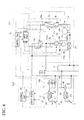
- FIG. 1 illustrates an overall configuration of a multi-type air conditioning system according to this embodiment.
- a multi-type air conditioning system 200 includes one outdoor unit 1, a plurality of indoor units 3, 3, ..., and a high-pressure gas pipe (main pipe) 5, a low-pressure gas pipe (main pipe) 7, and a liquid pipe 9 that connect the outdoor unit 1 and the plurality of indoor units 3, 3, ....
- the outdoor unit 1 mainly includes a compressor 10, outdoor expansion valves (expansion valves) 11a and 11b, outdoor heat exchangers 12a and 12b, outdoor four-way valves 14a and 14b, an accumulator 20, a receiver 23, and a double tube heat exchanger 25.
- the outdoor heat exchangers 12a and 12b perform heat exchange between outdoor air and a refrigerant, and operate as a condenser or an evaporator according to a state of a passing refrigerant.
- the outdoor expansion valves (expansion valves) 11a and 11b are provided in the liquid pipe 9 between the outdoor heat exchangers 12a and 12b and the receiver 23 and near the outdoor heat exchangers 12a and 12b. Electronic expansion valves are used as the outdoor expansion valves 11a and 11b.
- the outdoor heat exchangers 12a and 12b include liquid pipe side temperature sensors 30a and 30b provided on a side of the liquid pipe 9, and four-way valve side temperature sensors 32a and 32b provided on a side of the outdoor four-way valves 14a and 14b.
- an outdoor temperature sensor 34 is provided that measures an outdoor temperature, that is, an outside air temperature.
- a refrigerant compressed by the compressors 10 is a high-pressure gas refrigerant, and discharged to the high-pressure gas pipe 5.
- the high-pressure gas pipe 5 includes a high-pressure pressure sensor PSH for measuring pressure of a discharged refrigerant.
- a discharge pipe of each compressor 10 includes a discharge pipe temperature sensor 36 that measures a discharge pipe temperature.
- the high-pressure gas pipe 5 placed in the outdoor unit 1 is divided at branch points 5a and 5b, and branch pipes 6a and 6b thereof are connected to the outdoor four-way valves 14a and 14b at high-pressure gas pipe ports 14-1.
- the outdoor four-way valves 14a and 14b include outdoor heat exchanger side ports 14-2 connected to the outdoor heat exchangers 12a and 12b, low-pressure gas pipe side ports 14-3 connected to the outdoor side low-pressure gas branch pipes 15a and 15b divided at a branch point 7d of the low-pressure gas pipe 7, and bypass pipe side ports 14-4 connected via strainers 17a and 17b and capillary tubes 18a and 18b to outdoor side low-pressure gas branch pipes 15a and 15b.
- the liquid pipe 9 is connected to a side of the outdoor heat exchanger 12a and 12b opposite to a side connected to the outdoor four-way valves 14a and 14b.
- a receiver 23 that accumulates a liquid refrigerant
- a double tube heat exchanger 25 that supercools a refrigerant flowing through the liquid pipe 9 in a cooling operation are provided.
- the double tube heat exchanger 25 takes out a part of the liquid refrigerant flowing through the liquid pipe 9, and supercools the liquid refrigerant flowing through the liquid pipe 9 using a refrigerant expanded and evaporated by an expansion valve 25a and cooled,
- the gas refrigerant used for supercooling and evaporated is returned to the accumulator 20.
- a plurality of indoor units 3 are provided.
- Each indoor unit 3 includes an indoor heat exchanger 40 that performs heat exchange with indoor air.
- the indoor heat exchanger 40 includes temperature sensors 33 and 35 for measuring temperatures at front and rear thereof. Near the indoor heat exchanger 40, an indoor temperature sensor 37 for measuring a room temperature is provided.
- a liquid refrigerant branch pipe 44 that connects the indoor heat exchanger 40 and the liquid pipe 9 includes an indoor expansion valve 42.
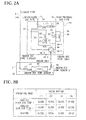
- an indoor unit 3C that is provided in a server room or the like and performs only the cooling operation includes a gas pipe pressure control kit (evaporating pressure adjustment mechanism) 100 connected to only the low-pressure gas pipe 7.
- a gas pipe pressure control kit evaporating pressure adjustment mechanism
- the indoor unit 3 other than the indoor unit 3C that performs only the cooling operation includes, between the indoor unit 3 and the outdoor unit 1, a refrigerant flow branch controller (cooling/heating operation switching mechanism) 46 that switches between the high-pressure gas pipe 5 and the low-pressure gas pipe 7.
- a refrigerant flow branch controller cooling/heating operation switching mechanism
- the refrigerant flow branch controller 46 includes an indoor four-way valve 48.
- the indoor four-way valve 48 includes a high-pressure gas pipe port 48-1 (first port) connected to a high-pressure gas branch pipe 5c branching off from a main pipe of the high-pressure gas pipe 5, an indoor heat exchanger side port 48-2 (second port) connected to a side of the indoor heat exchanger 40, a low-pressure gas pipe port 48-3 (third port) connected to an indoor side low-pressure gas branch pipe 7c branching off from a main pipe of the low-pressure gas pipe 7, and a low-pressure bypass pipe port 48-4 (fourth port) connected to a low-pressure bypass pipe 50 merging with a mid-position 49 of the indoor side low-pressure gas branch pipe 7c.
- the indoor four-way valve 48 provides communication between the high-pressure gas pipe port 48-1 and the low-pressure bypass pipe port 48-4 and communication between the indoor heat exchanger side port 48-2 and the low-gas pipe port 48-3 in the cooling operation.
- the indoor four-way valve 48 provides communication between the high-pressure gas pipe port 48-1 and the indoor heat exchanger side port 48-2 and communication between the low-pressure gas pipe port 48-3 and the low-pressure bypass pipe port 48-4 in the heating operation.
- a high-pressure gas branch pipe on-off valve (first on-off valve) 52 is provided in the high-pressure gas branch pipe 5c on the upstream side of the indoor four-way valve 48.
- a high-pressure gas branch pipe bypass pipe (high-pressure bypass pipe) 54 is formed so as to bypass the high-pressure gas branch pipe on-off valve 52, and the high-pressure gas branch pipe bypass pipe 54 includes a first capillary tube 55.
- the high-pressure gas branch pipe bypass pipe 54 has one end connected to an upstream side of the high-pressure gas branch pipe 5c beyond the high-pressure gas branch pipe on-off valve 52, and the other end connected to a downstream side of the high-pressure gas branch pipe 5c beyond the high-pressure gas branch pipe on-off valve 52, and bypasses the high-pressure gas branch pipe on-off valve 52.
- the low-pressure bypass pipe 50 on a downstream side of the indoor four-way valve 48 includes a second capillary tube 57.
- a first high/low-pressure bypass pipe 58 is provided between the high-pressure gas branch pipe 5c on the upstream side of the high-pressure gas branch pipe bypass pipe 54 and the indoor side low-pressure gas branch pipe 7c on the downstream side of the low-pressure bypass pipe 50 (downstream side of the mid-position 49).
- the first high/low-pressure bypass pipe 58 includes a first high/low-pressure bypass on-off valve 60 and a third capillary tube 62 in order from the side of the high-pressure gas branch pipe 5c toward the indoor side low-pressure gas branch pipe 7c.
- a second high/low- pressure bypass pipe (high/low-pressure bypass pipe) 63 is provided having one end connected to the high-pressure gas branch pipe 5c between a downstream side of the high-pressure gas branch pipe bypass pipe 54 and the high-pressure gas pipe port 48-1 of the indoor four-way valve 48, and the other end connected to the indoor side low-pressure gas branch pipe 7c on the downstream side of the low-pressure bypass pipe 50 (downstream side of the mid-position 49).
- the second high/low-pressure bypass pipe 63 includes a second high/low-pressure bypass on-off valve (second on-off valve) 64 and a fourth capillary tube 65 in order from the side of the high-pressure gas branch pipe 5c toward the indoor side low-pressure gas branch pipe 7c.
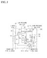
- the gas pipe pressure control kit 100 is provided on the indoor side low-pressure gas branch pipe 7c the indoor unit 3c and the outdoor unit 1.
- the indoor side low-pressure gas branch pipe 7c is divided into a plurality of branch pipes 102a, 102b and 102c in the gas pipe pressure control kit 100.
- the gas pipe pressure control kit 100 includes a plurality of, in this embodiment, three electromagnetic valves (valves) 101a, 101b and 101c.
- an air conditioning system 200 includes an outdoor control device CL1 that controls the outdoor unit 1, and an indoor control device CL2 that controls the indoor unit 3.
- an indoor control device CL2 is provided for each indoor unit 3.
- the outdoor control device CL1 and the indoor control device CL2 communicate with each other.
- FIG. 4 only one of the outdoor heat exchangers 12a and 12b and one of the outdoor four-way valves 14a and 14b are shown.
- the outdoor control device CL1 includes a control part 70 and an input part 72.
- the control part 70 calculates control values based on data obtained from the input part 72.
- the control values are sent to control devices such as the outdoor expansion valve 11a, an outdoor fan F1, the outdoor four-way valve 14a, or the compressor 10. Calculation results of the control part 70 are sent to an input part 82 of the indoor control device CL2.
- output values are input of a liquid pipe side temperature sensor 30a provided in the outdoor heat exchanger 12a, a four-way valve side temperature sensor 32a, an outdoor temperature sensor 34 provided near the outdoor heat exchanger 12a, a discharge pipe temperature sensor 36 provided in a discharge pipe of the compressor 10, a high-pressure pressure sensor PSH, and a low-pressure pressure sensor PSL and a suction pipe temperature sensor 38 provided on the upstream side of the accumulator 20.
- the indoor control device CL2 includes a control part 80 and the input part 82.
- the control part 80 calculates control values based on data obtained from the input part 82.
- the control values are sent to devices to be controlled such as the indoor expansion valve 42, an indoor fan F2, the indoor four-way valve 48 of the refrigerant flow branch controller 46, or electromagnetic valves 101a, 101b and 101c of the gas pipe pressure control kit 100.
- Calculation results of the control part 80 are sent to the input part 72 of the outdoor control device CL1.
- the outdoor control device CL1 and the indoor control device CL2 each include at least a CPU as a processor, a RAM or the like as a main memory, and a recording medium on which a program for operating the air conditioning system 200 is recorded.
- each CPU reads the program recorded on the storage medium and processes and calculates information, and thus operates the air conditioning system 200 according to a purpose.
- the indoor unit 3 including the refrigerant flow branch controller 46 can switch and perform the cooling operation and the heating operation depending on seasons.
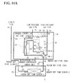
- FIG. 2B shows setting examples of an opening/closing state of the indoor four-way valve 48, the high-pressure gas branch pipe on-off valve 52, the first high/low-pressure bypass on-off valve 60, and the second high/low-pressure bypass on-off valve 64 in the cooling operation (when an outside air temperature is high: high outside air and when the outside air temperature is low: low outside air) and the heating operation.
- a high-pressure gas refrigerant having flown from the outdoor unit 1 to the outdoor heat exchangers 12a and 12b in the indoor unit 3 exchanges heat with the outside air and dissipates heat, and is condensed and liquefied.
- both the outdoor expansion valves 11a and 11b are opened, and the condensed and liquefied high-pressure liquid refrigerant passes through the outdoor expansion valves 11a and 11b and then passes through the receiver 23, is supercooled by the double tube heat exchanger 25 and then guided through the liquid pipe 9 to the indoor unit 3.
- the double tube heat exchanger 25 is desirably provided to prevent the liquid refrigerant from being evaporated in the liquid pipe 9.
- the high-pressure liquid refrigerant having flown into the indoor unit 3 that performs the cooling operation flows as described below.
- the high-pressure liquid refrigerant diverges to the liquid refrigerant branch pipe 44 connected to the indoor unit 3, then narrowed by the indoor expansion valve 42 in the indoor unit 3 and expanded. Then, the liquid refrigerant is evaporated by the indoor heat exchanger 40 and takes heat from indoor air and cool the indoor air.
- the evaporated low-pressure gas refrigerant flows into the indoor four-way valve 48 in the refrigerant flow branch controller 46.
- the indoor four-way valve 48 provides communication between the high-pressure gas pipe port 48-1 and the low-pressure bypass pipe port 48-4 and communication between the indoor heat exchanger side port 48-2 and the low-pressure gas pipe port 48-3.
- the low-pressure gas refrigerant from the indoor heat exchanger 40 passes through the indoor four-way valve 48 and flows into the indoor side low-pressure gas branch pipe 7c, then passes through the low-pressure gas pipe 7 as a main pipe and is guided to the outdoor unit 1.
- the high-pressure gas refrigerant flows as described below.
- the high-pressure gas refrigerant having flown through the high-pressure gas branch pipe 5c branching off from the high-pressure gas pipe 5 to each indoor unit 3 passes through the high-pressure gas branch pipe bypass pipe 54 and decompressed by the first capillary tube 55 since the high-pressure gas branch pipe on-off valve 52 is closed.
- the decompressed gas refrigerant flows through the indoor four-way valve 48 into the low-pressure bypass pipe 50, is narrowed by the second capillary tube 57 and adjusted in flow rate, and then merges with the indoor side low-pressure gas branch pipe 7c at the mid-position 49.
- the first high/low-pressure bypass on-off valve 60 of the refrigerant flow branch controller 46 is closed, and thus no high-pressure gas refrigerant flows through the first high/low-pressure bypass pipe 58.
- the low-pressure gas refrigerant having flown through the low-pressure gas pipe 7 into the outdoor unit 1 is subjected to gas-liquid separation by the accumulator 20 and returned to the compressor 10a.
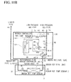
- the refrigerant flow branch controller 46 of the indoor unit 3 that performs the heating operation operates as described below.
- the indoor four-way valve 48 in the refrigerant flow branch controller 46 provides communication between the high-pressure gas pipe port 48-1 and the indoor heat exchanger side port 48-2 and communication between the low-pressure gas pipe port 48-3 and the low-pressure bypass pipe port 48-4.
- the high-pressure gas refrigerant fed from the high-pressure gas pipe 5 is guided through the indoor four-way valve 48 to the indoor heat exchanger 40, and condensed and liquefied by the indoor heat exchanger 40 to apply heat to the indoor air and heat the indoor air.
- the high-pressure liquid refrigerant liquefied by the indoor heat exchanger 40 passes through the liquid refrigerant branch pipe 44 and merges with the liquid pipe 9 as a main pipe.
- the first high/low-pressure bypass on-off valve 60 of the refrigerant flow branch controller 46 is closed and functions as a check valve to prevent backflow of the refrigerant
- FIG. 3B shows examples of opening/closing patterns of the three electromagnetic valves 101a, 101b and 101c in the pressure control kit 100 used for the control.
- pattern 1 in the cooling operation the three electromagnetic valves 101a, 101b and 101c are opened, in pattern 2, the two electromagnetic valves 101a and 101b are opened, and in pattern 3, only one electromagnetic valve 101a is opened.
- Step S101 After the operation of the indoor unit 3c is started (Step S101), it is determined whether a detection temperature of the temperature sensor 33 provided in the indoor unit 3c is higher than a predetermined temperature (for example, 3°C in the example in FIG. 6 ) (Step S102).
- a predetermined temperature for example, 3°C in the example in FIG. 6
- the cooling operation is set to pattern I (see FIG. 3B ), and the three electromagnetic valves 101a, 101b and 101c are opened (Step S103).
- Step S102 when the detection temperature is not higher than the predetermined temperature, the cooling operation is set to pattern 2 (see FIG. 3B ), the two electromagnetic valves 101a and 101b are opened, and the remaining electromagnetic valve 101c is closed (Step S104).
- Step S105 After a predetermined set timer time (for example, 120 sec) has passed and an operation state is stabilized, it is determined whether the detection temperature of the temperature sensor 33 provided in the indoor unit 3c is higher than the predetermined temperature (for example, 3°C in the example in FIG. 6 ) (Step S105).
- the detection temperature is the predetermined temperature or more
- the cooling operation is set to pattern 2 (see FIG. 3B ), the two electromagnetic valves 101a and 101b are opened, and the remaining electromagnetic valve 101c is kept closed (Step S106).
- Step S105 when the detection temperature is not higher than the predetermined temperature, the cooling operation is set to pattern 3 (see FIG. 3B ), only one electromagnetic valve 101a is opened, and the other electromagnetic valves 101b and 101c are closed (Step S107).
- Such a series of processes is repeated for each predetermined sampling time (for example, 120 sec).
- the indoor unit 3c that always performs the cooling operation includes the gas pipe pressure control kit 100 including the plurality of electromagnetic valves 101a, 101b and 101c, and controls opening/closing of the electromagnetic valves 101a, 101b and 101c according to a suction temperature of the refrigerant, and thus pressure loss of the refrigerant guided via the indoor heat exchanger 40 through the low-pressure gas pipe 7 to the outdoor unit 1 can be adjusted.
- evaporating pressure of the refrigerant in the indoor heat exchanger 40 can be adjusted, This can prevent a suction temperature from dropping to below zero, and prevent the indoor heat exchanger 40 from freezing in the indoor unit 3c that performs the cooling operation even when the outside air temperature is low, the other indoor unit 3 performs the heating operation, and the outdoor unit 1 functions as an evaporator.
- the cooling operation can be continuously performed, thereby increasing a cooling capacity of the indoor unit 3C that always performs the cooling operation.
- Such a gas pipe pressure control kit 100 is separate from the refrigerant flow branch controller 46, and the indoor unit 3c that always performs the cooling operation may include the gas pipe pressure control kit 100, and the other indoor unit 3c may include the refrigerant flow branch controller 46.
- the refrigerant flow branch controller 46 may have the function of the gas pipe pressure control kit 100, which increases costs depending on the number of indoor units 3. However, providing the gas pipe pressure control kit 100 or the refrigerant flow branch controller 46 may be selected as required, thereby achieving the above-described advantage with low costs.
- the indoor unit is intended for cooling or for both cooling and heating, providing the gas pipe pressure control kit 100 or the refrigerant flow branch controller 46 as hardware is selected rather than control by software.
- the gas pipe pressure control kit 100 or the refrigerant flow branch controller 46 is selected rather than control by software.
- the gas pipe pressure control kit 100 includes the three electromagnetic valves 101a, 101b and 101c, but not limited to three, the gas pipe pressure control kit 100 may include two or four or more electromagnetic valves.
- This embodiment is different from the first embodiment in that all indoor units include a refrigerant flow branch controller (cooling/heating operation switching mechanism) 120 described below instead of the refrigerant flow branch controller 46 and the gas pipe pressure control kit 100 described in the first embodiment.
- An outdoor unit 1 and an indoor unit 3 have the same configurations as in the first embodiment, and thus differences from the first embodiment will be mainly described and descriptions on the same configurations will be omitted.
- the refrigerant flow branch controller 120 provided in all indoor units 3 includes an indoor four-way valve 48.
- the indoor four-way valve 48 includes a high-pressure gas pipe port 48-1 connected to a high-pressure gas branch pipe 5c branching off from a main pipe of the high-pressure gas pipe 5, an indoor heat exchanger side port 48-2 connected to an indoor heat exchanger 40, a low-pressure gas pipe port 48-3 connected to an indoor side low-pressure gas branch pipe 7c branching off from a main pipe of the low-pressure gas pipe 7, and a low-pressure bypass pipe port 48-4 connected to a low-pressure bypass pipe 50 merging with a mid-position 49 of the indoor side low-pressure gas branch pipe 7c.
- the indoor four-way valve 48 provides communication between the high-pressure gas pipe port 48-1 and the low-pressure bypass pipe port 48-4 and communication between the indoor heat exchanger side port 48-2 and the low-pressure gas pipe port 48-3 in the cooling operation.
- the indoor four-way valve 48 provides communication between the high-pressure gas pipe port 48-1 and the indoor heat exchanger side port 48-2 and communication between the low-pressure gas pipe port 48-3 and the low-pressure bypass pipe port 48-4 in the heating operation.
- a high-pressure gas branch pipe on-off valve (first on-off valve) 52 is provided in the high-pressure gas branch pipe 5c on an upstream side of the indoor four-way valve 48.
- a high-pressure gas branch pipe bypass (high-pressure bypass pipe) 54 is formed so as to bypass the high-pressure gas branch pipe on-off valve 52, and the high-pressure gas branch pipe bypass pipe 54 includes a first capillary tube 55.
- the high-pressure gas branch pipe bypass pipe 54 has one end connected to an upstream side of the high-pressure gas branch pipe 5c beyond the high-pressure gas branch pipe on-off valve 52, and the other end connected to a downstream side of the high-pressure gas branch pipe 5c beyond the high-pressure gas branch pipe on-off valve 52, and bypasses the high-pressure gas branch pipe on-off valve 52.
- the low-pressure bypass pipe 50 on a downstream side of the indoor four-way valve 48 includes a second capillary tube 57.
- a first high/low-pressure bypass pipe 58 is provided the high-pressure gas branch pipe 5c on the upstream side of the high-pressure gas branch pipe bypass pipe 54 and the indoor side low-pressure gas branch pipe 7c on the downstream side of the low-pressure bypass pipe 50 (downstream side of the mid-position 49).
- the first high/low-pressure bypass pipe 58 includes a first high/low-pressure bypass on-off valve 60 and a third capillary tube 62 in order from the side of the high-pressure gas branch pipe 5c toward the indoor side low-pressure gas branch pipe 7c.
- a second high/low-pressure bypass pipe (high/low-pressure bypass pipe) 63 is provided having one end connected to the high-pressure gas branch pipe 5c between a downstream side of the high-pressure gas branch pipe bypass pipe 54 and the high-pressure gas pipe port 48-1 of the indoor four-way valve 48, and the other end connected to the indoor side low-pressure gas branch pipe 7c on the downstream side of the low-pressure bypass pipe 50 (downstream side of the mid-position 49).
- the second high/low-pressure bypass pipe 63 includes a second high/low-pressure bypass on-off valve (second on-off valve) 64 and a fourth capillary tube 65 in order from the side of the high-pressure gas branch pipe 5c toward the indoor side low-pressure gas branch pipe 7c.
- a supercooling heat exchanger 121 is provided between the indoor side low-pressure gas branch pipe 7c and the liquid pipe 9.
- a general double pipe heat exchanger including a combination of two copper pipes having different diameters or a plate heat exchanger may be used.
- the supercooling heat exchanges 121 is provided to supercool a refrigerant in a liquid pipe 9 in cooling.
- the refrigerant flow branch controller 120 includes a temperature sensor 123 on an outlet side of the supercooling heat exchanger 121 in the indoor side low-pressure gas branch pipe 7c.
- An indoor control device CL2 controls the refrigerant flow branch controller 120 in the same manner as in the first embodiment in a heating operation. At this time, opening of the indoor expansion valve 42 of the indoor unit 3 is controlled based an a temperature difference between temperature sensors 33 and 35.
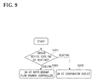
- FIG. 9 shows a control flow for switching opening adjustment control of the indoor expansion valve 42 in the heating operation and the cooling operation.
- the supercooling heat exchanges 121 supercools the refrigerant in the liquid pipe 9, and thus a liquid refrigerant with low enthalpy can be fed to the indoor unit 3.
- the indoor unit 3 can make use of a sufficient cooling capacity while ensuring an amount of circulated refrigerant.
- this can prevent the liquid refrigerant from returning through the liquid pipe 9 to the compressor 10, prevent failure of the compressor 10, and increase reliability of the system.
- FIG. 1 a third embodiment of a multi-type air conditioning system according to the present invention will be described.
- This embodiment is different from the first embodiment in that all indoor units include a refrigerant flow branch controller (cooling/heating operation switching mechanism) 130 described below instead of the refrigerant flow branch controller 46 and the gas pipe pressure control kit 100 described in the first embodiment.
- An outdoor unit 1 and an indoor unit 3 have the same configurations as in the first embodiment, and thus differences from the first embodiment will be mainly described and descriptions on the same configurations will be omitted.
- the refrigerant flow branch controller 130 provided in all indoor units 3 includes an indoor four-way valve 48.
- the indoor four-way valve 48 includes a high-pressure gas pipe port 48-1 connected to a high-pressure gas branch pipe 5c branching off from a main pipe of the high-pressure gas pipe 5, an indoor heat exchanger side port 48-2 connected to an indoor heat exchanger 40, a low-pressure gas pipe port 48-3 connected to an indoor side tow-pressure gas branch pipe 7c branching off from a main pipe of the low-pressure gas pipe 7, and a low-pressure bypass pipe port 48-4 connected to a tow-pressure bypass pipe 50 merging with a mid-position 49 of the indoor side low-pressure gas branch pipe 7c.
- the indoor four-way valve 48 communication the high-pressure gas pipe port 48-1 and the tow-pressure bypass pipe port 48-4 and communication between the indoor heat exchanger side port 48-2 and the low-pressure gas pipe port 48-3 in the cooling operation.
- the indoor four-way valve 48 provides communication the high-pressure gas pipe port 48-1 and the indoor heat exchanger port 48-2 and communication the low-pressure gas port 48-3 and the low-pressure bypass pipe port 48-4 in the heating operation.
- a high-pressure gas branch pipe on-off valve (first on-off valve) 52 is provided in the high-pressure gas branch pipe 5c on an upstream side of the indoor four-way valve 48.
- the refrigerant flow branch controller 130 does not include a high-pressure gas branch pipe bypass pipe 54 and a first capillary tube 55.
- the low-pressure bypass pipe 50 on a downstream side of the indoor four-way valve 48 includes a second capillary tube 57.
- a first high/low-pressure bypass pipe 58 is provided between the high-pressure gas branch pipe 5c on the upstream side of the high-pressure gas branch pipe bypass pipe 54 and the indoor side low-pressure gas branch pipe 7c on the downstream side of the low-pressure bypass pipe 50 (downstream side of the mid-position 49).
- the first high/low-pressure bypass pipe 58 includes a first high/low-pressure bypass on-off valve 60 and a third capillary tube 62 in order from the side of the high-pressure gas branch pipe 5c toward the indoor side low-pressure gas branch pipe 7c.
- a second high/low-pressure bypass pipe (high/low-pressure bypass pipe) 63 is provided having one end connected to the high-pressure gas branch pipe 5c between a downstream side of the high-pressure gas branch pipe bypass pipe 54 and the high-pressure gas pipe port 48-1 of the indoor four-way valve 48, and the other end connected to the indoor tow-pressure gas branch pipe 7c on the downstream or the low-pressure bypass pipe 50 (downstream or the mid-position 49).
- the second high/low-pressure bypass pipe 63 includes a second high/low-pressure bypass on-off valve (second on-off value) 64 and a fourth capillary tube 65 in order from the side of the high-pressure gas branch pipe 5c toward the indoor side low-pressure gas branch pipe 7c.
- An overheating heat exchanger 131 is provided between the mid-position 49 of the indoor side low-pressure gas branch pipe 7c and the second high/low-pressure bypass pipe 63.
- a general double pipe heat exchanger including a combination of two copper pipes having different diameters or a plate heat exchanger may be used.
- the overheating heat exchanger 131 is provided to overheat a refrigerant in a liquid pipe 9 in cooling.
- the refrigerant flow branch controller 130 includes a temperature sensor 133 on an outlet side of the overheating heat exchanger 131 in the indoor side low-pressure gas branch pipe 7c.
- An indoor control device CL2 controls the refrigerant flow branch controller 130 in the same manner as in the first embodiment in a heating operation. At this time, opening of the indoor expansion valve 42 of the indoor unit 3 is controlled based on a temperature difference between temperature sensors 33 and 35.
- FIG. 9 shows a control flow for switching opening adjustment control of the indoor expansion valve 42 in the heating operation and the cooling operation.
- the opening adjustment control of the indoor expansion valve 42 is performed with SH at the heat exchanger outlet (Step S202), and when the indoor unit 3 performs the cooling operation, the opening adjustment control of the indoor expansion valve 42 is performed with SH at the refrigerant flow branch controller outlet (Step S203).
- the overheating heat exchanger 131 in the cooling operation, can overheat a high-temperature high-pressure liquid refrigerant condensed by the indoor heat exchanger 40, thereby allowing the refrigerant to positively flow toward the low pressure side gas pipe. At this time, even if a liquid phase remains in the refrigerant, the heat exchange by the overheating heat exchanger 131 allows an unevaporated liquid refrigerant to be evaporated.
- the indoor unit 3 can make use of a sufficient cooling capacity while ensuring an amount of circulated refrigerant.
- pressure loss occurs in the overheating heat exchanger 131 to increase an evaporating temperature of the refrigerant in the indoor heat exchanger 40, thereby preventing the indoor heat exchanger 40 from freezing.
- the cooling operation can be continuously performed, thereby increasing a cooling capacity of the indoor unit 3 that always performs the cooling operation.
Landscapes
- Engineering & Computer Science (AREA)
- Physics & Mathematics (AREA)
- Mechanical Engineering (AREA)
- Thermal Sciences (AREA)
- General Engineering & Computer Science (AREA)
- Compression-Type Refrigeration Machines With Reversible Cycles (AREA)
- Air Conditioning Control Device (AREA)
Applications Claiming Priority (1)
| Application Number | Priority Date | Filing Date | Title |
|---|---|---|---|
| JP2010190396A JP5901107B2 (ja) | 2010-08-27 | 2010-08-27 | マルチ型空気調和システム |
Publications (3)
| Publication Number | Publication Date |
|---|---|
| EP2426438A2 true EP2426438A2 (de) | 2012-03-07 |
| EP2426438A3 EP2426438A3 (de) | 2014-07-30 |
| EP2426438B1 EP2426438B1 (de) | 2019-07-10 |
Family
ID=44936156
Family Applications (1)
| Application Number | Title | Priority Date | Filing Date |
|---|---|---|---|
| EP11178952.5A Not-in-force EP2426438B1 (de) | 2010-08-27 | 2011-08-26 | Klimaanlagensystem mit mehreren Einheiten |
Country Status (2)
| Country | Link |
|---|---|
| EP (1) | EP2426438B1 (de) |
| JP (1) | JP5901107B2 (de) |
Cited By (6)
| Publication number | Priority date | Publication date | Assignee | Title |
|---|---|---|---|---|
| EP3001122A1 (de) * | 2014-09-18 | 2016-03-30 | Fujitsu General Limited | Ausseneinheit einer klimaanlage und klimaanlage |
| EP3156743A1 (de) * | 2015-10-13 | 2017-04-19 | Mitsubishi Heavy Industries, Ltd. | Klimaanlagenvorrichtung |
| EP2339268A3 (de) * | 2009-12-22 | 2017-05-03 | Samsung Electronics Co., Ltd. | Wärmepumpenvorrichtung und Außeneinheit damit |
| CN106931547A (zh) * | 2017-03-29 | 2017-07-07 | 广东美的暖通设备有限公司 | 空调系统及空调系统的控制方法 |
| EP3315880A4 (de) * | 2015-06-26 | 2018-06-20 | Daikin Industries, Ltd. | Klimatisierungssystem |
| CN113531773A (zh) * | 2021-06-18 | 2021-10-22 | 宁波奥克斯电气股份有限公司 | 一种多联空调故障检测方法、装置及多联空调 |
Families Citing this family (6)
| Publication number | Priority date | Publication date | Assignee | Title |
|---|---|---|---|---|
| WO2015020114A1 (ja) | 2013-08-09 | 2015-02-12 | サラヤ株式会社 | 新型ソホロリピッド化合物及びそれを含有する組成物 |
| CN104061713A (zh) * | 2014-06-03 | 2014-09-24 | 东莞市新时代新能源科技有限公司 | 温度调节系统 |
| JP6608586B2 (ja) * | 2014-08-21 | 2019-11-20 | 株式会社ササクラ | 冷房システム及びその制御方法 |
| WO2017199276A1 (ja) * | 2016-05-16 | 2017-11-23 | 東芝キヤリア株式会社 | 空気調和機 |
| CN107120809B (zh) * | 2017-06-13 | 2019-12-17 | 珠海格力电器股份有限公司 | 一种空调系统的控制方法、装置及空调系统 |
| KR102373851B1 (ko) | 2017-08-31 | 2022-03-14 | 삼성전자주식회사 | 공기조화기 |
Citations (2)
| Publication number | Priority date | Publication date | Assignee | Title |
|---|---|---|---|---|
| JP2005300006A (ja) | 2004-04-12 | 2005-10-27 | Hitachi Ltd | マルチ型空気調和機 |
| JP2009210139A (ja) | 2008-02-29 | 2009-09-17 | Mitsubishi Heavy Ind Ltd | マルチ型空気調和機 |
Family Cites Families (11)
| Publication number | Priority date | Publication date | Assignee | Title |
|---|---|---|---|---|
| JP3062824B2 (ja) * | 1990-11-21 | 2000-07-12 | 株式会社日立製作所 | 空気調和システム |
| JPH07180927A (ja) * | 1994-07-25 | 1995-07-18 | Sanyo Electric Co Ltd | 多室型冷暖房装置 |
| JP4104218B2 (ja) * | 1998-08-28 | 2008-06-18 | 三洋電機株式会社 | 空気調和装置 |
| JP4206870B2 (ja) * | 2003-08-29 | 2009-01-14 | 三菱電機株式会社 | 冷凍サイクル装置 |
| JP2006125761A (ja) * | 2004-10-29 | 2006-05-18 | Mitsubishi Heavy Ind Ltd | 室内機およびこれを備えた空気調和装置 |
| KR100688171B1 (ko) * | 2004-12-29 | 2007-03-02 | 엘지전자 주식회사 | 냉난방 동시형 멀티 공기조화기 및 냉매 회수방법 |
| KR100677266B1 (ko) * | 2005-02-17 | 2007-02-02 | 엘지전자 주식회사 | 냉난방 동시형 멀티 에어컨 |
| KR20070074302A (ko) * | 2006-01-09 | 2007-07-12 | 삼성전자주식회사 | 공기 조화기 및 그 제어 방법 |
| JP4981411B2 (ja) * | 2006-11-01 | 2012-07-18 | 三菱重工業株式会社 | 空気調和機 |
| JP5132354B2 (ja) * | 2008-02-21 | 2013-01-30 | 三菱電機株式会社 | 空気調和装置 |
| JP4767340B2 (ja) * | 2009-07-30 | 2011-09-07 | 三菱電機株式会社 | ヒートポンプ装置の制御装置 |
-
2010
- 2010-08-27 JP JP2010190396A patent/JP5901107B2/ja not_active Expired - Fee Related
-
2011
- 2011-08-26 EP EP11178952.5A patent/EP2426438B1/de not_active Not-in-force
Patent Citations (2)
| Publication number | Priority date | Publication date | Assignee | Title |
|---|---|---|---|---|
| JP2005300006A (ja) | 2004-04-12 | 2005-10-27 | Hitachi Ltd | マルチ型空気調和機 |
| JP2009210139A (ja) | 2008-02-29 | 2009-09-17 | Mitsubishi Heavy Ind Ltd | マルチ型空気調和機 |
Cited By (8)
| Publication number | Priority date | Publication date | Assignee | Title |
|---|---|---|---|---|
| EP2339268A3 (de) * | 2009-12-22 | 2017-05-03 | Samsung Electronics Co., Ltd. | Wärmepumpenvorrichtung und Außeneinheit damit |
| EP3001122A1 (de) * | 2014-09-18 | 2016-03-30 | Fujitsu General Limited | Ausseneinheit einer klimaanlage und klimaanlage |
| EP3315880A4 (de) * | 2015-06-26 | 2018-06-20 | Daikin Industries, Ltd. | Klimatisierungssystem |
| US10852042B2 (en) | 2015-06-26 | 2020-12-01 | Daikin Industries, Ltd. | Air conditioning system |
| EP3156743A1 (de) * | 2015-10-13 | 2017-04-19 | Mitsubishi Heavy Industries, Ltd. | Klimaanlagenvorrichtung |
| CN106931547A (zh) * | 2017-03-29 | 2017-07-07 | 广东美的暖通设备有限公司 | 空调系统及空调系统的控制方法 |
| CN106931547B (zh) * | 2017-03-29 | 2020-01-07 | 广东美的暖通设备有限公司 | 空调系统及空调系统的控制方法 |
| CN113531773A (zh) * | 2021-06-18 | 2021-10-22 | 宁波奥克斯电气股份有限公司 | 一种多联空调故障检测方法、装置及多联空调 |
Also Published As
| Publication number | Publication date |
|---|---|
| JP5901107B2 (ja) | 2016-04-06 |
| EP2426438A3 (de) | 2014-07-30 |
| JP2012047409A (ja) | 2012-03-08 |
| EP2426438B1 (de) | 2019-07-10 |
Similar Documents
| Publication | Publication Date | Title |
|---|---|---|
| EP2426438B1 (de) | Klimaanlagensystem mit mehreren Einheiten | |
| EP2557377B1 (de) | Verbundsystem für klimatisierung und heisswasserversorgung | |
| EP3521732B1 (de) | Klimaanlage | |
| AU2004267299B2 (en) | Refrigeration system | |
| US8307668B2 (en) | Air conditioner | |
| EP2375188B1 (de) | Klimaanlage | |
| CN100504245C (zh) | 冷冻装置 | |
| EP2128535A1 (de) | Klimaanlage | |
| EP2128541A1 (de) | Kühlvorrichtung | |
| US11927376B2 (en) | Refrigeration cycle apparatus | |
| US11022354B2 (en) | Air conditioner | |
| EP3088809B1 (de) | Klimaanlage | |
| EP2339269B1 (de) | Klimaanlage | |
| JP5310101B2 (ja) | 空気調和装置 | |
| US12173922B2 (en) | Sequential hot gas reheat system in an air conditioning unit | |
| EP1881277A1 (de) | Klimaanlage | |
| EP2896911B1 (de) | Klimaanlagenvorrichtung | |
| JP4001171B2 (ja) | 冷凍装置 | |
| EP2314954B1 (de) | Kühlvorrichtung | |
| JP2008267653A (ja) | 冷凍装置 | |
| EP2515055A1 (de) | Klimaanlage | |
| EP3156743A1 (de) | Klimaanlagenvorrichtung | |
| EP1643196B1 (de) | Klimaanlage | |
| EP1643195B1 (de) | Mehrzonenklimaanlage und Verfahren zur Steuerung derselben | |
| JP5463995B2 (ja) | 多室型空気調和装置 |
Legal Events
| Date | Code | Title | Description |
|---|---|---|---|
| AK | Designated contracting states |
Kind code of ref document: A2 Designated state(s): AL AT BE BG CH CY CZ DE DK EE ES FI FR GB GR HR HU IE IS IT LI LT LU LV MC MK MT NL NO PL PT RO RS SE SI SK SM TR |
|
| AX | Request for extension of the european patent |
Extension state: BA ME |
|
| PUAI | Public reference made under article 153(3) epc to a published international application that has entered the european phase |
Free format text: ORIGINAL CODE: 0009012 |
|
| RIC1 | Information provided on ipc code assigned before grant |
Ipc: F25B 29/00 20060101ALI20140228BHEP Ipc: F25B 13/00 20060101AFI20140228BHEP |
|
| PUAL | Search report despatched |
Free format text: ORIGINAL CODE: 0009013 |
|
| AK | Designated contracting states |
Kind code of ref document: A3 Designated state(s): AL AT BE BG CH CY CZ DE DK EE ES FI FR GB GR HR HU IE IS IT LI LT LU LV MC MK MT NL NO PL PT RO RS SE SI SK SM TR |
|
| AX | Request for extension of the european patent |
Extension state: BA ME |
|
| RIC1 | Information provided on ipc code assigned before grant |
Ipc: F25B 13/00 20060101AFI20140624BHEP Ipc: F25B 29/00 20060101ALI20140624BHEP |
|
| 17P | Request for examination filed |
Effective date: 20150126 |
|
| RBV | Designated contracting states (corrected) |
Designated state(s): AL AT BE BG CH CY CZ DE DK EE ES FI FR GB GR HR HU IE IS IT LI LT LU LV MC MK MT NL NO PL PT RO RS SE SI SK SM TR |
|
| RAP1 | Party data changed (applicant data changed or rights of an application transferred) |
Owner name: MITSUBISHI HEAVY INDUSTRIES THERMAL SYSTEMS, LTD. |
|
| GRAP | Despatch of communication of intention to grant a patent |
Free format text: ORIGINAL CODE: EPIDOSNIGR1 |
|
| STAA | Information on the status of an ep patent application or granted ep patent |
Free format text: STATUS: GRANT OF PATENT IS INTENDED |
|
| INTG | Intention to grant announced |
Effective date: 20190212 |
|
| GRAS | Grant fee paid |
Free format text: ORIGINAL CODE: EPIDOSNIGR3 |
|
| GRAA | (expected) grant |
Free format text: ORIGINAL CODE: 0009210 |
|
| STAA | Information on the status of an ep patent application or granted ep patent |
Free format text: STATUS: THE PATENT HAS BEEN GRANTED |
|
| AK | Designated contracting states |
Kind code of ref document: B1 Designated state(s): AL AT BE BG CH CY CZ DE DK EE ES FI FR GB GR HR HU IE IS IT LI LT LU LV MC MK MT NL NO PL PT RO RS SE SI SK SM TR |
|
| REG | Reference to a national code |
Ref country code: GB Ref legal event code: FG4D |
|
| REG | Reference to a national code |
Ref country code: CH Ref legal event code: EP Ref country code: AT Ref legal event code: REF Ref document number: 1154019 Country of ref document: AT Kind code of ref document: T Effective date: 20190715 |
|
| REG | Reference to a national code |
Ref country code: DE Ref legal event code: R096 Ref document number: 602011060312 Country of ref document: DE |
|
| REG | Reference to a national code |
Ref country code: IE Ref legal event code: FG4D |
|
| REG | Reference to a national code |
Ref country code: NL Ref legal event code: MP Effective date: 20190710 |
|
| REG | Reference to a national code |
Ref country code: LT Ref legal event code: MG4D |
|
| REG | Reference to a national code |
Ref country code: AT Ref legal event code: MK05 Ref document number: 1154019 Country of ref document: AT Kind code of ref document: T Effective date: 20190710 |
|
| PG25 | Lapsed in a contracting state [announced via postgrant information from national office to epo] |
Ref country code: LT Free format text: LAPSE BECAUSE OF FAILURE TO SUBMIT A TRANSLATION OF THE DESCRIPTION OR TO PAY THE FEE WITHIN THE PRESCRIBED TIME-LIMIT Effective date: 20190710 Ref country code: PT Free format text: LAPSE BECAUSE OF FAILURE TO SUBMIT A TRANSLATION OF THE DESCRIPTION OR TO PAY THE FEE WITHIN THE PRESCRIBED TIME-LIMIT Effective date: 20191111 Ref country code: FI Free format text: LAPSE BECAUSE OF FAILURE TO SUBMIT A TRANSLATION OF THE DESCRIPTION OR TO PAY THE FEE WITHIN THE PRESCRIBED TIME-LIMIT Effective date: 20190710 Ref country code: NL Free format text: LAPSE BECAUSE OF FAILURE TO SUBMIT A TRANSLATION OF THE DESCRIPTION OR TO PAY THE FEE WITHIN THE PRESCRIBED TIME-LIMIT Effective date: 20190710 Ref country code: SE Free format text: LAPSE BECAUSE OF FAILURE TO SUBMIT A TRANSLATION OF THE DESCRIPTION OR TO PAY THE FEE WITHIN THE PRESCRIBED TIME-LIMIT Effective date: 20190710 Ref country code: HR Free format text: LAPSE BECAUSE OF FAILURE TO SUBMIT A TRANSLATION OF THE DESCRIPTION OR TO PAY THE FEE WITHIN THE PRESCRIBED TIME-LIMIT Effective date: 20190710 Ref country code: BG Free format text: LAPSE BECAUSE OF FAILURE TO SUBMIT A TRANSLATION OF THE DESCRIPTION OR TO PAY THE FEE WITHIN THE PRESCRIBED TIME-LIMIT Effective date: 20191010 Ref country code: NO Free format text: LAPSE BECAUSE OF FAILURE TO SUBMIT A TRANSLATION OF THE DESCRIPTION OR TO PAY THE FEE WITHIN THE PRESCRIBED TIME-LIMIT Effective date: 20191010 Ref country code: AT Free format text: LAPSE BECAUSE OF FAILURE TO SUBMIT A TRANSLATION OF THE DESCRIPTION OR TO PAY THE FEE WITHIN THE PRESCRIBED TIME-LIMIT Effective date: 20190710 |
|
| PG25 | Lapsed in a contracting state [announced via postgrant information from national office to epo] |
Ref country code: IS Free format text: LAPSE BECAUSE OF FAILURE TO SUBMIT A TRANSLATION OF THE DESCRIPTION OR TO PAY THE FEE WITHIN THE PRESCRIBED TIME-LIMIT Effective date: 20191110 Ref country code: ES Free format text: LAPSE BECAUSE OF FAILURE TO SUBMIT A TRANSLATION OF THE DESCRIPTION OR TO PAY THE FEE WITHIN THE PRESCRIBED TIME-LIMIT Effective date: 20190710 Ref country code: AL Free format text: LAPSE BECAUSE OF FAILURE TO SUBMIT A TRANSLATION OF THE DESCRIPTION OR TO PAY THE FEE WITHIN THE PRESCRIBED TIME-LIMIT Effective date: 20190710 Ref country code: GR Free format text: LAPSE BECAUSE OF FAILURE TO SUBMIT A TRANSLATION OF THE DESCRIPTION OR TO PAY THE FEE WITHIN THE PRESCRIBED TIME-LIMIT Effective date: 20191011 Ref country code: LV Free format text: LAPSE BECAUSE OF FAILURE TO SUBMIT A TRANSLATION OF THE DESCRIPTION OR TO PAY THE FEE WITHIN THE PRESCRIBED TIME-LIMIT Effective date: 20190710 Ref country code: RS Free format text: LAPSE BECAUSE OF FAILURE TO SUBMIT A TRANSLATION OF THE DESCRIPTION OR TO PAY THE FEE WITHIN THE PRESCRIBED TIME-LIMIT Effective date: 20190710 |
|
| PG25 | Lapsed in a contracting state [announced via postgrant information from national office to epo] |
Ref country code: TR Free format text: LAPSE BECAUSE OF FAILURE TO SUBMIT A TRANSLATION OF THE DESCRIPTION OR TO PAY THE FEE WITHIN THE PRESCRIBED TIME-LIMIT Effective date: 20190710 |
|
| PG25 | Lapsed in a contracting state [announced via postgrant information from national office to epo] |
Ref country code: DK Free format text: LAPSE BECAUSE OF FAILURE TO SUBMIT A TRANSLATION OF THE DESCRIPTION OR TO PAY THE FEE WITHIN THE PRESCRIBED TIME-LIMIT Effective date: 20190710 Ref country code: EE Free format text: LAPSE BECAUSE OF FAILURE TO SUBMIT A TRANSLATION OF THE DESCRIPTION OR TO PAY THE FEE WITHIN THE PRESCRIBED TIME-LIMIT Effective date: 20190710 Ref country code: PL Free format text: LAPSE BECAUSE OF FAILURE TO SUBMIT A TRANSLATION OF THE DESCRIPTION OR TO PAY THE FEE WITHIN THE PRESCRIBED TIME-LIMIT Effective date: 20190710 Ref country code: RO Free format text: LAPSE BECAUSE OF FAILURE TO SUBMIT A TRANSLATION OF THE DESCRIPTION OR TO PAY THE FEE WITHIN THE PRESCRIBED TIME-LIMIT Effective date: 20190710 Ref country code: IT Free format text: LAPSE BECAUSE OF FAILURE TO SUBMIT A TRANSLATION OF THE DESCRIPTION OR TO PAY THE FEE WITHIN THE PRESCRIBED TIME-LIMIT Effective date: 20190710 |
|
| PG25 | Lapsed in a contracting state [announced via postgrant information from national office to epo] |
Ref country code: SM Free format text: LAPSE BECAUSE OF FAILURE TO SUBMIT A TRANSLATION OF THE DESCRIPTION OR TO PAY THE FEE WITHIN THE PRESCRIBED TIME-LIMIT Effective date: 20190710 Ref country code: SK Free format text: LAPSE BECAUSE OF FAILURE TO SUBMIT A TRANSLATION OF THE DESCRIPTION OR TO PAY THE FEE WITHIN THE PRESCRIBED TIME-LIMIT Effective date: 20190710 Ref country code: LI Free format text: LAPSE BECAUSE OF NON-PAYMENT OF DUE FEES Effective date: 20190831 Ref country code: IS Free format text: LAPSE BECAUSE OF FAILURE TO SUBMIT A TRANSLATION OF THE DESCRIPTION OR TO PAY THE FEE WITHIN THE PRESCRIBED TIME-LIMIT Effective date: 20200224 Ref country code: LU Free format text: LAPSE BECAUSE OF NON-PAYMENT OF DUE FEES Effective date: 20190826 Ref country code: CH Free format text: LAPSE BECAUSE OF NON-PAYMENT OF DUE FEES Effective date: 20190831 Ref country code: MC Free format text: LAPSE BECAUSE OF FAILURE TO SUBMIT A TRANSLATION OF THE DESCRIPTION OR TO PAY THE FEE WITHIN THE PRESCRIBED TIME-LIMIT Effective date: 20190710 Ref country code: CZ Free format text: LAPSE BECAUSE OF FAILURE TO SUBMIT A TRANSLATION OF THE DESCRIPTION OR TO PAY THE FEE WITHIN THE PRESCRIBED TIME-LIMIT Effective date: 20190710 |
|
| REG | Reference to a national code |
Ref country code: BE Ref legal event code: MM Effective date: 20190831 |
|
| REG | Reference to a national code |
Ref country code: DE Ref legal event code: R097 Ref document number: 602011060312 Country of ref document: DE |
|
| PLBE | No opposition filed within time limit |
Free format text: ORIGINAL CODE: 0009261 |
|
| STAA | Information on the status of an ep patent application or granted ep patent |
Free format text: STATUS: NO OPPOSITION FILED WITHIN TIME LIMIT |
|
| PG2D | Information on lapse in contracting state deleted |
Ref country code: IS |
|
| PG25 | Lapsed in a contracting state [announced via postgrant information from national office to epo] |
Ref country code: IE Free format text: LAPSE BECAUSE OF NON-PAYMENT OF DUE FEES Effective date: 20190826 |
|
| 26N | No opposition filed |
Effective date: 20200603 |
|
| PG25 | Lapsed in a contracting state [announced via postgrant information from national office to epo] |
Ref country code: BE Free format text: LAPSE BECAUSE OF NON-PAYMENT OF DUE FEES Effective date: 20190831 Ref country code: SI Free format text: LAPSE BECAUSE OF FAILURE TO SUBMIT A TRANSLATION OF THE DESCRIPTION OR TO PAY THE FEE WITHIN THE PRESCRIBED TIME-LIMIT Effective date: 20190710 |
|
| PG25 | Lapsed in a contracting state [announced via postgrant information from national office to epo] |
Ref country code: CY Free format text: LAPSE BECAUSE OF FAILURE TO SUBMIT A TRANSLATION OF THE DESCRIPTION OR TO PAY THE FEE WITHIN THE PRESCRIBED TIME-LIMIT Effective date: 20190710 |
|
| PG25 | Lapsed in a contracting state [announced via postgrant information from national office to epo] |
Ref country code: MT Free format text: LAPSE BECAUSE OF FAILURE TO SUBMIT A TRANSLATION OF THE DESCRIPTION OR TO PAY THE FEE WITHIN THE PRESCRIBED TIME-LIMIT Effective date: 20190710 Ref country code: HU Free format text: LAPSE BECAUSE OF FAILURE TO SUBMIT A TRANSLATION OF THE DESCRIPTION OR TO PAY THE FEE WITHIN THE PRESCRIBED TIME-LIMIT; INVALID AB INITIO Effective date: 20110826 |
|
| PG25 | Lapsed in a contracting state [announced via postgrant information from national office to epo] |
Ref country code: MK Free format text: LAPSE BECAUSE OF FAILURE TO SUBMIT A TRANSLATION OF THE DESCRIPTION OR TO PAY THE FEE WITHIN THE PRESCRIBED TIME-LIMIT Effective date: 20190710 |
|
| REG | Reference to a national code |
Ref country code: DE Ref legal event code: R082 Ref document number: 602011060312 Country of ref document: DE Representative=s name: CBDL PATENTANWAELTE GBR, DE Ref country code: DE Ref legal event code: R082 Ref document number: 602011060312 Country of ref document: DE Representative=s name: CBDL PATENTANWAELTE EGBR, DE |
|
| PGFP | Annual fee paid to national office [announced via postgrant information from national office to epo] |
Ref country code: DE Payment date: 20240702 Year of fee payment: 14 |
|
| PGFP | Annual fee paid to national office [announced via postgrant information from national office to epo] |
Ref country code: GB Payment date: 20240701 Year of fee payment: 14 |
|
| PGFP | Annual fee paid to national office [announced via postgrant information from national office to epo] |
Ref country code: FR Payment date: 20240702 Year of fee payment: 14 |
|
| REG | Reference to a national code |
Ref country code: DE Ref legal event code: R119 Ref document number: 602011060312 Country of ref document: DE |
|
| GBPC | Gb: european patent ceased through non-payment of renewal fee |
Effective date: 20250826 |
|
| PG25 | Lapsed in a contracting state [announced via postgrant information from national office to epo] |
Ref country code: GB Free format text: LAPSE BECAUSE OF NON-PAYMENT OF DUE FEES Effective date: 20250826 |
|
| PG25 | Lapsed in a contracting state [announced via postgrant information from national office to epo] |
Ref country code: DE Free format text: LAPSE BECAUSE OF NON-PAYMENT OF DUE FEES Effective date: 20260303 |
|
| PG25 | Lapsed in a contracting state [announced via postgrant information from national office to epo] |
Ref country code: FR Free format text: LAPSE BECAUSE OF NON-PAYMENT OF DUE FEES Effective date: 20250831 |