EP2426689A2 - Procédé de commutation d'une charge inductive et circuit de raccordement pour l'exécution du procédé - Google Patents
Procédé de commutation d'une charge inductive et circuit de raccordement pour l'exécution du procédé Download PDFInfo
- Publication number
- EP2426689A2 EP2426689A2 EP20110178297 EP11178297A EP2426689A2 EP 2426689 A2 EP2426689 A2 EP 2426689A2 EP 20110178297 EP20110178297 EP 20110178297 EP 11178297 A EP11178297 A EP 11178297A EP 2426689 A2 EP2426689 A2 EP 2426689A2
- Authority
- EP
- European Patent Office
- Prior art keywords
- voltage
- medium voltage
- medium
- circuit
- time
- Prior art date
- Legal status (The legal status is an assumption and is not a legal conclusion. Google has not performed a legal analysis and makes no representation as to the accuracy of the status listed.)
- Withdrawn
Links
Images


Classifications
-
- H—ELECTRICITY
- H02—GENERATION; CONVERSION OR DISTRIBUTION OF ELECTRIC POWER
- H02H—EMERGENCY PROTECTIVE CIRCUIT ARRANGEMENTS
- H02H9/00—Emergency protective circuit arrangements for limiting excess current or voltage without disconnection
- H02H9/001—Emergency protective circuit arrangements for limiting excess current or voltage without disconnection limiting speed of change of electric quantities, e.g. soft switching on or off
- H02H9/002—Emergency protective circuit arrangements for limiting excess current or voltage without disconnection limiting speed of change of electric quantities, e.g. soft switching on or off limiting inrush current on switching on of inductive loads subjected to remanence, e.g. transformers
-
- H—ELECTRICITY
- H02—GENERATION; CONVERSION OR DISTRIBUTION OF ELECTRIC POWER
- H02P—CONTROL OR REGULATION OF ELECTRIC MOTORS, ELECTRIC GENERATORS OR DYNAMO-ELECTRIC CONVERTERS; CONTROLLING TRANSFORMERS, REACTORS OR CHOKE COILS
- H02P9/00—Arrangements for controlling electric generators for the purpose of obtaining a desired output
- H02P9/10—Control effected upon generator excitation circuit to reduce harmful effects of overloads or transients, e.g. sudden application of load, sudden removal of load, sudden change of load
-
- H—ELECTRICITY
- H01—ELECTRIC ELEMENTS
- H01H—ELECTRIC SWITCHES; RELAYS; SELECTORS; EMERGENCY PROTECTIVE DEVICES
- H01H33/00—High-tension or heavy-current switches with arc-extinguishing or arc-preventing means
- H01H33/02—Details
- H01H33/59—Circuit arrangements not adapted to a particular application of the switch and not otherwise provided for, e.g. for ensuring operation of the switch at a predetermined point in the AC cycle
- H01H33/593—Circuit arrangements not adapted to a particular application of the switch and not otherwise provided for, e.g. for ensuring operation of the switch at a predetermined point in the AC cycle for ensuring operation of the switch at a predetermined point of the AC cycle
-
- H—ELECTRICITY
- H01—ELECTRIC ELEMENTS
- H01H—ELECTRIC SWITCHES; RELAYS; SELECTORS; EMERGENCY PROTECTIVE DEVICES
- H01H9/00—Details of switching devices, not covered by groups H01H1/00 - H01H7/00
- H01H9/54—Circuit arrangements not adapted to a particular application of the switching device and for which no provision exists elsewhere
- H01H9/56—Circuit arrangements not adapted to a particular application of the switching device and for which no provision exists elsewhere for ensuring operation of the switch at a predetermined point in the AC cycle
-
- H—ELECTRICITY
- H02—GENERATION; CONVERSION OR DISTRIBUTION OF ELECTRIC POWER
- H02K—DYNAMO-ELECTRIC MACHINES
- H02K3/00—Details of windings
- H02K3/04—Windings characterised by the conductor shape, form or construction, e.g. with bar conductors
- H02K3/28—Layout of windings or of connections between windings
Definitions
- the present invention relates to the field of electric power generation. It relates to a method for connecting an inductive load, in particular a winding through the stator bore of a generator, to a predetermined AC voltage in the medium voltage range according to the preamble of claim 1. It further relates to a connection circuit for carrying out the method.
- a medium voltage of 6-10 kV must be connected and connected to a coil or winding consisting of 5-12 turns of a medium-voltage cable exists, which is wound through the stator bore. So far, the medium voltage has been switched on, that a conventional medium-voltage circuit breaker has been closed from an associated panel.
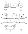
- the basic arrangement for this procedure is in Fig. 1 shown.
- a winding 13 of a generator 12 via a connection circuit 11 with a medium-voltage switch panel 14 is connected.
- An embodiment of the method according to the invention is characterized in that the connection takes place when the medium voltage passes through its phase maximum.
- Another embodiment of the inventive method is characterized in that the temporal course of the medium voltage is sampled, that it is determined when the medium voltage assumes an excellent value, which is reached a fixed period of time before passing through the predetermined phase position, and that after the expiration of the fixed Time span the connection takes place.
- the excellent value of the medium voltage is a zero crossing.
- Another embodiment is characterized in that the circuit breaker has its own delay time, and that the fixed period of time is greater than the delay time of the circuit breaker.
- Another embodiment of the method according to the invention is characterized in that the circuit breaker of a medium-voltage switching field is used as the circuit breaker.
- Another embodiment of the method according to the invention is characterized in that a mean voltage of 6-10 kV is used.
- connection circuit for carrying out the method has medium-voltage connections for connecting the medium voltage and winding connections for connecting the inductive load, which are interconnected via a power switch, wherein between the medium-voltage terminals and the circuit breaker, a first voltage converter is arranged, the output of the first voltage converter to the Input of a zero-crossing detector is connected, and the zero-crossing detector via a subsequent delay circuit controls the power switch.
- connection circuit is characterized in that the delay time of the delay circuit is adjustable.
- connection circuit is characterized in that a control panel is provided, via which the zero-crossing detector and the delay circuit can be put into a standby state.
- the idea underlying the invention is to minimize, as a first approximation, the inrush currents which occur during the performance of high-flux measurements by closing the associated circuit breaker which connects the associated winding to the medium-voltage source at the right time.
- the phase maximum of the AC voltage of the medium-voltage source is taken as the correct time.
- connection circuit 11 has two medium-voltage terminals 15a and 15b on the input side, to which the medium voltage used is applied.
- the medium-voltage terminals 15a and 15b connecting lines run to two output winding terminals 21a and 21b to which a winding 13 (turns of a medium voltage cable wound through the stator bore) of the generator 12 to be tested is connected.
- a separator 19 is inserted, with the aid of which the winding terminals 21 a and 21 b can be de-energized and grounded.
- a power switch 17 is inserted, which controls the actual switch-on.
- the control of the circuit breaker 17 is carried out in accordance with the time course of the medium voltage terminals 15a and 15b lying medium voltage.
- This alternating voltage is tapped via a voltage converter 16 and the output signal of the voltage converter 16 is fed to a zero-crossing detector 22, which detects the zero crossings of the alternating voltage and transmits corresponding signals to a delay circuit 23.
- the time delayed detector signals are then used to control the power switch 17. So that one of the delayed detector signals close the power switch 17 can, must first be prepared by a control panel 24 from the zero crossing detector 22 and the delay circuit 23 by corresponding signals (enable command) on standby. Once this is done, the next following detector signal from the zero-crossing detector 22 is used after appropriate delay in the delay circuit 23 to turn on the power switch 17.
- a further voltage converter 18 arranged between the power switch 17 and the isolator 19 can serve to monitor the behavior of the output voltage during the switch-on.
- a current transformer 20 can be used to control the flowing current during the switch-on process.
- a setting mode first the power switch 17 and the disconnector 19 are opened.
- the circuit breaker 17 is then closed and at the same time voltage profiles of the converter voltages VT1 and VT2 are recorded in an oscilloscopic manner (see Fig. 3 ).
- the delay time in the delay circuit 23 is now set so that the sum of the set delay time (T1 in Fig. 4 ) and from the delay switch (T2 in Fig. 4 ) Is just so large that the AC voltage then applied to the winding terminals 21 a and 21 b when the AC voltage reaches the maximum phase.
- connection circuit 11 can be used for carrying out the high-flow measurement of the generator.
- the disconnector 19 is permanently closed and from the control panel 24 is at the beginning of the test (time t1 in Fig. 4 ) is a ready signal to the zero-crossing detector 22 and the delay circuit 23. Is detected by the zero-crossing detector 22, the next zero crossing (time t2 in Fig. 4 ), the power switch 17 closes after passing the set delay time T1 and the inherent delay time T2 (time t3 in FIG Fig. 4 ), so that from there on the transducer voltage VT2 follows the course of the transducer voltage VT1.
- the flowchart comprises five sections FC1 to FC5.
- the first section FC1 designates the transition to the active test mode, in which the disconnector 19 is closed while the power switch 17 remains open. With a first command K1 then the devices 22 and 23 are put on standby. In the second section FC2, the next zero crossing is detected at the converter voltage VT1 of the voltage converter 16. In the third section FC3, the detector signal is subjected to a first time delay in the circuit 23. With a second command K2, the power switch 17 is commanded to turn on. After expiration of the inherent delay time of the circuit breaker (section FC4), the power switch 17 is actually closed (section FC5).
Landscapes
- Engineering & Computer Science (AREA)
- Power Engineering (AREA)
- Control Of Eletrric Generators (AREA)
- Tests Of Circuit Breakers, Generators, And Electric Motors (AREA)
- Electronic Switches (AREA)
Applications Claiming Priority (1)
| Application Number | Priority Date | Filing Date | Title |
|---|---|---|---|
| DE201010044600 DE102010044600A1 (de) | 2010-09-07 | 2010-09-07 | Verfahren zum Zuschalten einer induktiven Last sowie Anschlussschaltung zur Durchführung des Verfahrens |
Publications (2)
| Publication Number | Publication Date |
|---|---|
| EP2426689A2 true EP2426689A2 (fr) | 2012-03-07 |
| EP2426689A3 EP2426689A3 (fr) | 2013-03-06 |
Family
ID=44763825
Family Applications (1)
| Application Number | Title | Priority Date | Filing Date |
|---|---|---|---|
| EP20110178297 Withdrawn EP2426689A3 (fr) | 2010-09-07 | 2011-08-22 | Procédé de commutation d'une charge inductive et circuit de raccordement pour l'exécution du procédé |
Country Status (7)
| Country | Link |
|---|---|
| US (1) | US20120056496A1 (fr) |
| EP (1) | EP2426689A3 (fr) |
| JP (1) | JP2012080759A (fr) |
| KR (1) | KR20120025436A (fr) |
| CN (1) | CN102403841A (fr) |
| CA (1) | CA2751768A1 (fr) |
| DE (1) | DE102010044600A1 (fr) |
Families Citing this family (4)
| Publication number | Priority date | Publication date | Assignee | Title |
|---|---|---|---|---|
| EP2608357B1 (fr) * | 2011-12-19 | 2014-07-23 | Vetco Gray Controls Limited | Protection contre les transitoires dans un système de communication |
| KR101723463B1 (ko) * | 2015-05-28 | 2017-04-07 | 창신정보통신(주) | 부하유형에 따라 출력전원의 온/오프 시점을 제어할 수 있는 각구제어 멀티탭 |
| JP7188259B2 (ja) * | 2019-04-22 | 2022-12-13 | 株式会社ジェイテクト | 信号入力装置及び信号検出方法 |
| CN112083231B (zh) * | 2020-08-21 | 2023-04-25 | 中国大唐集团科学技术研究院有限公司西北电力试验研究院 | 一种能减小合闸冲击电流的发电机定子铁心损耗试验装置 |
Family Cites Families (9)
| Publication number | Priority date | Publication date | Assignee | Title |
|---|---|---|---|---|
| DE366854C (de) * | 1923-01-12 | Aeg | Vorrichtung zum Anschalten eisenhaltiger Spulen an Wechselstromspannungen | |
| DE1082322B (de) * | 1954-02-22 | 1960-05-25 | Koch & Sterzel Kommanditgesell | Einrichtung zum Aus- oder Einschalten eines z. B. einen Transformator, insbesondere Roentgentransformator, enthaltenden Wechselstromkreises |
| DE2530047C3 (de) * | 1975-07-04 | 1979-06-21 | Siemens Ag, 1000 Berlin Und 8000 Muenchen | Anordnung zum Anschalten von Transformatoren, insbesondere leerlaufenden Transformatoren, an eine Wechselspannungsquelle |
| US4370564A (en) * | 1980-06-04 | 1983-01-25 | Ricoh Company, Ltd. | AC Switching device |
| AT384502B (de) * | 1985-09-10 | 1987-11-25 | Sprecher & Schuh Ag | Einrichtung zum gesteuerten ein- und/oder ausschalten von induktiven und kapazitiven elementen im hochspannungsnetz |
| DE3614057A1 (de) * | 1986-04-25 | 1987-10-29 | Heidelberger Druckmasch Ag | Verfahren und schaltungsanordnung zum anschalten einer mit einer remanenz behafteten induktivitaet |
| JP2892717B2 (ja) * | 1989-11-15 | 1999-05-17 | 株式会社日立製作所 | 電力開閉制御装置 |
| GB0421443D0 (en) * | 2004-09-27 | 2004-10-27 | Unsworth Peter | Point on wave (pow) control for motor starting and switching |
| JP5248269B2 (ja) * | 2008-10-31 | 2013-07-31 | 株式会社東芝 | 遮断器の開閉制御装置、及び遮断器の開閉制御システム |
-
2010
- 2010-09-07 DE DE201010044600 patent/DE102010044600A1/de not_active Withdrawn
-
2011
- 2011-08-22 EP EP20110178297 patent/EP2426689A3/fr not_active Withdrawn
- 2011-08-26 US US13/218,668 patent/US20120056496A1/en not_active Abandoned
- 2011-09-06 JP JP2011193631A patent/JP2012080759A/ja not_active Withdrawn
- 2011-09-06 CA CA 2751768 patent/CA2751768A1/fr not_active Abandoned
- 2011-09-06 KR KR20110090233A patent/KR20120025436A/ko not_active Ceased
- 2011-09-06 CN CN2011102766100A patent/CN102403841A/zh active Pending
Non-Patent Citations (1)
| Title |
|---|
| None |
Also Published As
| Publication number | Publication date |
|---|---|
| KR20120025436A (ko) | 2012-03-15 |
| EP2426689A3 (fr) | 2013-03-06 |
| US20120056496A1 (en) | 2012-03-08 |
| JP2012080759A (ja) | 2012-04-19 |
| CN102403841A (zh) | 2012-04-04 |
| DE102010044600A1 (de) | 2012-03-08 |
| CA2751768A1 (fr) | 2012-03-07 |
Similar Documents
| Publication | Publication Date | Title |
|---|---|---|
| EP2282399B1 (fr) | Convertisseur statique et procédé de démarrage du convertisseur | |
| DE102011083514A1 (de) | Gleichspannungs-Leistungsschalter | |
| WO2018046708A1 (fr) | Disjoncteur | |
| EP3576284A1 (fr) | Couplage électrique d'un premier réseau électrique avec un second réseau électrique | |
| EP2426689A2 (fr) | Procédé de commutation d'une charge inductive et circuit de raccordement pour l'exécution du procédé | |
| WO1999053593A1 (fr) | Dispositif et procede pour alimenter en energie electrique une charge electrique | |
| EP1475645A1 (fr) | Circuit pour le test synthétique d'interrupteurs haute tension à courant alternatif | |
| DE102008024348B4 (de) | Verfahren zur Reduktion pulsförmiger Erdströme an einem elektrischen Großgerät und Kompensationsschaltung zur Erdstromverlagerung | |
| EP2901537A1 (fr) | Dispositif de transformation | |
| EP3161921A1 (fr) | Procédé permettant d'interrompre un courant électrique dans une ligne de tension continue et utilisation du procédé | |
| AT509837B1 (de) | Vorrichtung zur fehlerstromreduktion | |
| EP3080822B1 (fr) | Dispositif et procédé visant à réduire une composante de flux magnétique continu dans le noyau d'un transformateur triphasé | |
| EP3262664B1 (fr) | Procédé permettant de modifier le nombre de spires actives d'un enroulement de régulation dans une installation électrique et installation électrique munie d'un enroulement de régulation | |
| WO2015169692A2 (fr) | Installation et procédé pour fournir une puissance réactive | |
| EP3646427B1 (fr) | Procédé et dispositif pour la connexion électrique d'un transformateur à un réseau électrique | |
| EP4088124B1 (fr) | Source de courant fort pour un système de contrôle servant à contrôler un dispositif à énergie électrique et système de contrôle | |
| DE202012001061U1 (de) | Testeinrichtung zum Erzeugen einer Überspannung | |
| Hashem et al. | Attenuation of transformer inrush current using controlled switching system on delta-star transformer | |
| AT515818A1 (de) | Verfahren und System zum Prüfen einer Schaltanlage für Energieübertragungsanlagen | |
| DE112014006555B4 (de) | Kommutierungsschaltung | |
| DE102012221952A1 (de) | Verfahren, Steuerungsvorrichtung und Pulsstromquelle zum Unterdrücken oder Unterbrechen eines Lichtbogens und Stromverteilungsstation | |
| DE68908237T2 (de) | Statische Thyristoreinrichtung für ein Mittelspannungswechselstromnetz. | |
| EP3402062B1 (fr) | Couplage d'au moins deux convertisseurs modulaires à niveaux multiples | |
| EP0842557A1 (fr) | Batterie de condensateurs commutee par des thyristors | |
| EP4690406A1 (fr) | Réseau de tension continue insensible aux défaillances |
Legal Events
| Date | Code | Title | Description |
|---|---|---|---|
| AK | Designated contracting states |
Kind code of ref document: A2 Designated state(s): AL AT BE BG CH CY CZ DE DK EE ES FI FR GB GR HR HU IE IS IT LI LT LU LV MC MK MT NL NO PL PT RO RS SE SI SK SM TR |
|
| AX | Request for extension of the european patent |
Extension state: BA ME |
|
| PUAI | Public reference made under article 153(3) epc to a published international application that has entered the european phase |
Free format text: ORIGINAL CODE: 0009012 |
|
| PUAL | Search report despatched |
Free format text: ORIGINAL CODE: 0009013 |
|
| AK | Designated contracting states |
Kind code of ref document: A3 Designated state(s): AL AT BE BG CH CY CZ DE DK EE ES FI FR GB GR HR HU IE IS IT LI LT LU LV MC MK MT NL NO PL PT RO RS SE SI SK SM TR |
|
| AX | Request for extension of the european patent |
Extension state: BA ME |
|
| RIC1 | Information provided on ipc code assigned before grant |
Ipc: H01H 33/59 20060101AFI20130128BHEP Ipc: H02H 9/00 20060101ALI20130128BHEP Ipc: H01H 9/56 20060101ALI20130128BHEP |
|
| 17P | Request for examination filed |
Effective date: 20130821 |
|
| RBV | Designated contracting states (corrected) |
Designated state(s): AL AT BE BG CH CY CZ DE DK EE ES FI FR GB GR HR HU IE IS IT LI LT LU LV MC MK MT NL NO PL PT RO RS SE SI SK SM TR |
|
| STAA | Information on the status of an ep patent application or granted ep patent |
Free format text: STATUS: THE APPLICATION IS DEEMED TO BE WITHDRAWN |
|
| 18D | Application deemed to be withdrawn |
Effective date: 20160301 |