EP2426801A1 - Barre omnibus, procédé de refroidissement associé et appareil électrique - Google Patents
Barre omnibus, procédé de refroidissement associé et appareil électrique Download PDFInfo
- Publication number
- EP2426801A1 EP2426801A1 EP10175089A EP10175089A EP2426801A1 EP 2426801 A1 EP2426801 A1 EP 2426801A1 EP 10175089 A EP10175089 A EP 10175089A EP 10175089 A EP10175089 A EP 10175089A EP 2426801 A1 EP2426801 A1 EP 2426801A1
- Authority
- EP
- European Patent Office
- Prior art keywords
- current
- pipe
- pipe section
- space
- conductor
- Prior art date
- Legal status (The legal status is an assumption and is not a legal conclusion. Google has not performed a legal analysis and makes no representation as to the accuracy of the status listed.)
- Withdrawn
Links
Images



Classifications
-
- H—ELECTRICITY
- H02—GENERATION; CONVERSION OR DISTRIBUTION OF ELECTRIC POWER
- H02G—INSTALLATION OF ELECTRIC CABLES OR LINES, OR OF COMBINED OPTICAL AND ELECTRIC CABLES OR LINES
- H02G5/00—Installations of bus-bars
- H02G5/10—Cooling
-
- H—ELECTRICITY
- H02—GENERATION; CONVERSION OR DISTRIBUTION OF ELECTRIC POWER
- H02B—BOARDS, SUBSTATIONS OR SWITCHING ARRANGEMENTS FOR THE SUPPLY OR DISTRIBUTION OF ELECTRIC POWER
- H02B1/00—Frameworks, boards, panels, desks, casings; Details of substations or switching arrangements
- H02B1/20—Bus-bar or other wiring layouts, e.g. in cubicles, in switchyards
-
- H—ELECTRICITY
- H02—GENERATION; CONVERSION OR DISTRIBUTION OF ELECTRIC POWER
- H02B—BOARDS, SUBSTATIONS OR SWITCHING ARRANGEMENTS FOR THE SUPPLY OR DISTRIBUTION OF ELECTRIC POWER
- H02B1/00—Frameworks, boards, panels, desks, casings; Details of substations or switching arrangements
- H02B1/56—Cooling; Ventilation
-
- H—ELECTRICITY
- H02—GENERATION; CONVERSION OR DISTRIBUTION OF ELECTRIC POWER
- H02B—BOARDS, SUBSTATIONS OR SWITCHING ARRANGEMENTS FOR THE SUPPLY OR DISTRIBUTION OF ELECTRIC POWER
- H02B13/00—Arrangement of switchgear in which switches are enclosed in, or structurally associated with, a casing, e.g. cubicle
- H02B13/02—Arrangement of switchgear in which switches are enclosed in, or structurally associated with, a casing, e.g. cubicle with metal casing
-
- H—ELECTRICITY
- H05—ELECTRIC TECHNIQUES NOT OTHERWISE PROVIDED FOR
- H05K—PRINTED CIRCUITS; CASINGS OR CONSTRUCTIONAL DETAILS OF ELECTRIC APPARATUS; MANUFACTURE OF ASSEMBLAGES OF ELECTRICAL COMPONENTS
- H05K7/00—Constructional details common to different types of electric apparatus
- H05K7/20—Modifications to facilitate cooling, ventilating, or heating
Definitions
- the invention resides in the field of medium and high voltage technologies and relates to a current-carrying segment, to an electrical apparatus, such as a gas insulated switchgear, and to a method for cooling a current-carrying segment, all according to the preamble of the corresponding independent claims.
- Gas insulated switchgear has the main function of protecting power supply systems, for example in case of short-circuits and overload fault currents, while maintaining service to unaffected circuits. Switchgear also provides isolation of circuits from power supplies. It is also used to enhance system availability by allowing more than one source to feed a load.
- gas insulated switchgear is one type.
- the preferred gas used for isolating conductors and contacts is SF 6 (sulphur hexafluoride), but other fluids, like insulating oil, are also used.
- One aspect to be considered when designing switchgear is the fact that resistive or ohmic losses in the conductors and contact resistances between different parts lead to a heating up of the switchgear and may further lead to failure of the system.
- the heat level depends, amongst others, on the current value through the conductors in relation to the resistive losses. Therefore, it is in some cases mandatory to provide appropriate cooling of the conductors in order to prevent damage and to comply with standards defining limits for acceptable temperatures. For example, at low currents natural convection of the insulating gas may be sufficient for cooling the conductors. However, as the dissipated power scales with the squared applied current, more powerful cooling mechanisms are required above a certain current level.
- German patent application DE 10 2008 049 435 A1 discloses a busbar arrangement comprising at least two partial conductors with a gap between one another.
- the busbar is enclosed in an encapsulating housing and is surrounded by insulating gas.
- a disadvantage of the proposed enhancement is the fact that the partial conductors are bound to a certain configuration. Furthermore, the arrangement does not account for enhancing the cooling of single conductors.
- a current-carrying segment comprising at least a current conductor, a shield at least partially enclosing the current conductor, and a housing for the current conductor, in particular a gas-tight housing for encapsulating the current conductor from the environment.
- the housing encloses the shield.
- a first space between the current conductor and the shield and a second space between the shield and the housing are filled with an insulating fluid.
- the current-carrying segment comprises at least one pipe for cooling the current conductor, arranged at least inside the first space.
- the pipe comprises at least one first pipe section having an entrance opening for the fluid and at least at least one second pipe section having an exit opening for the fluid.
- the first pipe section extends through the shield and the second pipe section encloses at least a portion of the current conductor.
- the objective is achieved by providing an electrical apparatus comprising at least one current-carrying segment according to the invention.
- the electrical apparatus is, in particular, a gas insulated switchgear, generator circuit breaker, high-voltage circuit breaker or load-break disconnector.
- a further objective of the invention is to provide a method for efficiently cooling electrical apparatuses. This objective is achieved by a method for cooling at least a current conductor of an electrical apparatus according to the invention. In a first step a current is applied to the current conductor, such that it heats up due to its losses, e.g. resistive losses or inductive losses.
- the current conductor is cooled by generating a convective flow of the insulating fluid in such a way that cold fluid from a bottom part of the second space with respect to the gravity force flows substantially against the direction of the gravity force into the lower pipe section, subsequently into the second pipe section through a space between inner walls of the second pipe section and outer walls of and/or slits in the enclosed portion of the current conductor, and finally out into the first or the second space.
- the advantage of said current-carrying segment or apparatus, respectively, is the possibility of efficiently cooling a current conductor by making use of the fact that the density of the fluid decreases with increasing temperature.
- the fluid rises inside the pipe when the fluid is heated up by the conductor.
- cold fluid from the bottom of the first and/or second space is sucked into the pipe.
- the pipe acts as a "chimney", using the chimney effect in the pipe for cooling the current conductor.
- cold gas is heavier than hot gas. Accordingly, cold insulating gas inside the housing tends to concentrate at the bottom of the housing and of the shield. Contrary to this, hot gas rises to the top of the housing and of the shield.
- gas located in the vicinity of a hot area at the surface of the conductor heats up and rises immediately to the top of the shield only or to the top of the housing only.
- a gas transfer which is favourable for cooling the conductor, can substantially take place merely in the upper half of the first or second space.
- conventional cooling is inefficient, because the coldest gas at the bottom of the housing, which has the highest cooling potential, is not used, and at least in some cases natural convection occurs only separately inside the shield and, if at all, outside the shield.
- the pipe according to the invention it is possible to "tap" the colder fluid pool at the bottom of the housing and make use of its high cooling potential, as well.
- a portion of the conductor, preferably a hot area, inside the pipe and having the pipe extending, in its longitudinal direction, from the vicinity of the bottom of the housing towards the top of the housing or the shield it is possible to force the cold gas at the bottom to travel through the pipe and efficiently cool the hot area of the conductor.
- Fig. 1 shows a cross section of a simplified gas insulated switchgear.
- a current conductor 2 extends in a longitudinal direction z.
- a shield 3 partially encloses the current conductor 2.
- a housing 4 for sealing off or encapsulating the conductor segment from the environment encloses the shield 3.
- a first space 5 between the current conductor 2 and the shield 3 and a second space 6 between the shield 3 and the housing 4 are filled with an insulating gas, preferably SF 6 .
- the shield 3 prevents electrical discharges between the conductor 2 and the housing 4.
- the direction y corresponds to the vertical direction.
- Fig. 2 shows a longitudinal sectional view of a Current-Carrying segment according to the prior art.
- the shield 3 is supported by holder elements 7.
- the insulating gas located both in the first and the second space 5, 6 cools the current conductor 2.
- Fig. 2 it is shown in a simplified manner how the cooling is accomplished.
- the arrows denote the path of the gas flow.
- dashed arrows represent hot gas and lined arrows represent cold or cooling gas. Gas located close to the outer conductor surface is heated up by the conductor, rises to the upper part of the shield 3 and escapes to the upper part of the housing 4 through an opening in the shield 3.
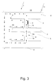
- Fig. 3 shows a longitudinal sectional view of a first embodiment of an electrical apparatus 11, such as a gas insulated switchgear, circuit breaker or disconnector, comprising at least one conductor segment 1 according to the invention.
- an electrical apparatus such as a gas insulated switchgear, circuit breaker or disconnector
- the arrangement of the current conductor 2, shield 3 and housing 4 is the same as described above.
- a pipe 9 for cooling a portion 2a of the conductor 2 is arranged inside the shield 3. It comprises a first pipe section 1a and a second pipe section 1b.
- the pipe is open, typically at end faces, and may transfer a fluid.
- the pipe is arranged substantially vertically.
- first and/or the second pipe sections 1a, 1b is or are elongated in a substantially vertical direction, however they may also run obliquely with respect to the vertical axis y. Both pipe sections 1a, 1b extend through the shield 3.
- the second pipe section 1b encloses a portion 2a of the current conductor 2 and, in particular, hermetically encloses said portion 2a of the current conductor 2.
- Fig. 3 also shows the gas flow using the same arrow types as Fig. 2 ; hot gas is denoted by dashed arrows and cold gas by lined arrows. For all subsequent figures, at least one hot area of the conductor 2 is assumed to be located within the portion 2a of the conductor 2.
- a hot area is defined as a part of the conductor 2 having a temperature above a specified level. Particularly, hot areas develop in the vicinity of contacts or of material impurities of the conductor 2. The hot areas are preferably determined by means of, particularly computer-aided, thermodynamics simulations.
- the gas is heated up and rises. As the gas path only leads through the pipe 9, it escapes directly into the second space 6 and continues circulating substantially along the cold housing 4.
- the gas flow is shown in a simplified manner, whereas in reality the flow may differ and may, for example, contain swirls or small swirls.
- the gas cools down again. This is also due to the fact that the housing 4 conducts a part of the heat of the rising hot gas to the environment 10. During the process of cooling down, the gas drops in the direction towards the bottom of the housing 4.
- the present invention makes use of the much colder gas located at the bottom of the housing 4 for a more efficient cooling of the conductor portion 2a.
- the extension of the second pipe section 1b through the shield 3 is particularly preferred, as it additionally accelerates the gas and takes it out to the second space, such that the gas has more time to cool off.
- the cross section or distribution of cross sections of the pipe 9 along its longitudinal extent necessary for an efficient cooling may be determined depending on at least one electrical and/or material parameter, such as e.g. ohmic losses in or around the current-carrying segment, density and heat capacity of the cooling gas at a given pressure, and/or velocity of the fluid.
- electrical and/or material parameter such as e.g. ohmic losses in or around the current-carrying segment, density and heat capacity of the cooling gas at a given pressure, and/or velocity of the fluid.
- the pipe 9 comprises optionally in addition a fin 8, extending into the pipe 9 and preferably extending vertically.
- the fin 8 increases the heat transfer to the wall.
- a plurality of fins 8 may be attached to the wall of the pipe 9, also in the lower section 1a.
- the fin 8 or fins may also be arranged to extend out from the pipe 9 and to protrude into the first space 5.
- fins 8 may be arranged on the inside and the outside at the walls of the pipe 9.
- the fin 8 may run substantially helically, however it is generally preferred that the fin runs substantially vertically in order to prevent gas from being hindered from rising up.
- the pipe 9 is mechanically connected to the current conductor 2 and the shield 3 (not shown), thereby forming a support for the shield 3.
- the pipe also replaces the holder elements 7 of Fig. 2 , thus fulfilling two tasks at a time, i.e. cooling the conductor 2 and self-dependent supporting the shield 3.
- Fig. 4 shows a perspective view of the first embodiment of the current-carrying segment 1 according to the invention.
- This figure shows the position of the pipe 9 inside the shield 3 in a more illustrative way.
- the housing 4 is omitted.
- the path of the gas circulation inside the pipe 9 can be seen in a better way; the dotted arrows show how the heated gas flows around the enclosed portion 2a of the conductor 2.
- the second pipe section 1b of the pipe 9 encloses a substantially toroidal space around the conductor 2.
- the second pipe section 1b may enclose a portion 2a of the current-carrying segment 1 which has slits (not shown), preferably vertical slits, for passing through the fluid.
- slits not shown
- the majority of the gas circulation takes place through the second space 6.
- the additional circulation inside the first space 5 of Fig. 3 is not shown here for clarity reasons.
- Fig. 5 shows a longitudinal sectional view of a second embodiment of a current-carrying segment 1 according to the invention.
- the arrangement is broadly the same as the one in Fig. 3 , except for the lower section 1a of the pipe 9.
- the first pipe section 1a protrudes beyond the shield 3 and into the second space 6 here. This advantageously prolongs the path of the gas and allows "tapping" gas from a lower or the lowest region of the second space 6, where colder or the coldest gas is located.
- the first pipe section 1a has two entrance openings 1d facing the housing 4.
- the second pipe section 1b particularly protrudes beyond the shield 3 and into an upper part of the second space 6. Furthermore, the second pipe section 1b has at least two exit openings 1c facing towards the housing 4. This has the advantage that a less turbulent stream or gas flow is created in an upper or the top part of the second space 6 and consequently that the heat is led further and/or faster away from the region of the chimney or pipe 9.
- Fig. 6 shows a longitudinal sectional view of a third embodiment of a current-carrying segment 1 according to the invention.
- the arrangement is broadly the same as the one in Fig. 3 , except for the second pipe section 1b of the pipe 9.
- the second pipe section 1b comprises a cylinder 1e arranged substantially concentrically with respect to the portion 2a of the current conductor 2 and forming an enclosed space around it.
- the first pipe section 1a is connected substantially to one axial end of the cylinder 1e.
- the second pipe section 1b comprising the cylinder 1e also comprises an extension, extending from the other axial end of the cylinder 1e through the shield 3, preferably in vertical upward direction.
- At least one hot spot of the current conductor 2 is cooled by means of the pipe 9, but a plurality of hot spots may particularly be cooled by means of a single pipe 9.
- the third embodiment described above is advantageous for cooling such a plurality of hot spots.
- the radial distance between an inner wall of the cylinder 1e to the conductor is chosen depending on the length of the cylinder 1e, thus depending on the horizontal path which has to be travelled by the gas in order to escape to the top and on the temperatures to be dissipated in that region.
- Fig. 7 shows a longitudinal sectional view of a fourth embodiment of a current-carrying segment 1 according to the invention.
- the arrangement is broadly the same as the one in Fig. 3 , except for the second pipe section 1b of the pipe 9.
- two second pipe sections 1b each enclosing a distinct portion 2a of the current conductor 2 are connected to the first pipe section 1a.
- more second pipe sections 1b are possible, as well.
- This embodiment particularly accounts for hot spots which are located at a too long distance from each other to be efficiently cooled by means of a single pipe according to one of the previous embodiments of the invention, but still are at a mutual distance allowing the usage of a single pipe 9 with a single first pipe section 1a and two or more second pipe sections 1b.
- Fig. 8 shows a longitudinal sectional view of a fifth embodiment of a current-carrying segment 1 according to the invention.
- the arrangement is broadly the same as the one in Fig. 3 , except for the second pipe section 1b of the pipe 9.
- the second pipe section 1b protrudes only into the first space 5.
- the gas rises towards the upper area of the shield 3 and escapes to or into the second space 6 via an opening connecting the first and the second space 5, 6, as shown on the left and the right side of the current-carrying segment 1.
- openings 1f may be provided in the shield 3 substantially above the exit opening 1c of the second pipe section 1b, such that gas may directly rise through these openings 1f and enter the second space 6.
- the arrows represent again the gas flow in a simplified way.
- the current-carrying conductor segment 1 of the invention can also be used for a generator circuit breaker or any hot parts of it. Another application is to use the current-carrying conductor segment 1 for a high voltage circuit breaker or load-break isolator or any hot parts of them, or for other high voltage or medium voltage equipment requiring and profiting from passive chimney-effect cooling as provided for by the pipe 9.
Landscapes
- Engineering & Computer Science (AREA)
- Power Engineering (AREA)
- Physics & Mathematics (AREA)
- Thermal Sciences (AREA)
- Microelectronics & Electronic Packaging (AREA)
- Driving Mechanisms And Operating Circuits Of Arc-Extinguishing High-Tension Switches (AREA)
- Cooling Or The Like Of Electrical Apparatus (AREA)
Priority Applications (3)
| Application Number | Priority Date | Filing Date | Title |
|---|---|---|---|
| EP10175089A EP2426801A1 (fr) | 2010-09-02 | 2010-09-02 | Barre omnibus, procédé de refroidissement associé et appareil électrique |
| KR1020110089032A KR20120024500A (ko) | 2010-09-02 | 2011-09-02 | 전류-운반 세그먼트, 그 냉각 방법, 및 전기 장치 |
| CN2011103193962A CN102386580A (zh) | 2010-09-02 | 2011-09-02 | 载流节段、用于冷却该载流节段的方法以及电气设备 |
Applications Claiming Priority (1)
| Application Number | Priority Date | Filing Date | Title |
|---|---|---|---|
| EP10175089A EP2426801A1 (fr) | 2010-09-02 | 2010-09-02 | Barre omnibus, procédé de refroidissement associé et appareil électrique |
Publications (1)
| Publication Number | Publication Date |
|---|---|
| EP2426801A1 true EP2426801A1 (fr) | 2012-03-07 |
Family
ID=43558240
Family Applications (1)
| Application Number | Title | Priority Date | Filing Date |
|---|---|---|---|
| EP10175089A Withdrawn EP2426801A1 (fr) | 2010-09-02 | 2010-09-02 | Barre omnibus, procédé de refroidissement associé et appareil électrique |
Country Status (3)
| Country | Link |
|---|---|
| EP (1) | EP2426801A1 (fr) |
| KR (1) | KR20120024500A (fr) |
| CN (1) | CN102386580A (fr) |
Families Citing this family (2)
| Publication number | Priority date | Publication date | Assignee | Title |
|---|---|---|---|---|
| WO2015018443A1 (fr) * | 2013-08-07 | 2015-02-12 | Abb S.P.A. | Appareil de refroidissement pour un dispositif électrique ou électronique et dispositif électrique ou électronique, en particulier un disjoncteur, comprenant ledit appareil de refroidissement |
| EP3097575B1 (fr) * | 2014-01-24 | 2023-03-01 | ABB Schweiz AG | Dispositif de refroidissement pour un appareillage de commutation isolé au gaz |
Citations (5)
| Publication number | Priority date | Publication date | Assignee | Title |
|---|---|---|---|---|
| FR1533299A (fr) * | 1967-06-05 | 1968-07-19 | Electro Entpr L | Perfectionnements aux liaisons de puissance à moyenne tension |
| US4091230A (en) * | 1976-08-09 | 1978-05-23 | Electric Power Research Institute, Inc. | Evaporation-cooled transmission line system |
| US4378461A (en) * | 1980-09-11 | 1983-03-29 | Tokyo Shibaura Denki Kabushiki Kaisha | Gas insulated bus with cooling means |
| US4539432A (en) * | 1983-01-27 | 1985-09-03 | Bbc Brown, Boveri & Company Limited | Coolable electrical component |
| DE102008049435A1 (de) | 2008-09-25 | 2010-04-01 | Siemens Aktiengesellschaft | Sammelschienenanordnung mit einem ersten und zweiten Teilleiter |
-
2010
- 2010-09-02 EP EP10175089A patent/EP2426801A1/fr not_active Withdrawn
-
2011
- 2011-09-02 KR KR1020110089032A patent/KR20120024500A/ko not_active Withdrawn
- 2011-09-02 CN CN2011103193962A patent/CN102386580A/zh active Pending
Patent Citations (5)
| Publication number | Priority date | Publication date | Assignee | Title |
|---|---|---|---|---|
| FR1533299A (fr) * | 1967-06-05 | 1968-07-19 | Electro Entpr L | Perfectionnements aux liaisons de puissance à moyenne tension |
| US4091230A (en) * | 1976-08-09 | 1978-05-23 | Electric Power Research Institute, Inc. | Evaporation-cooled transmission line system |
| US4378461A (en) * | 1980-09-11 | 1983-03-29 | Tokyo Shibaura Denki Kabushiki Kaisha | Gas insulated bus with cooling means |
| US4539432A (en) * | 1983-01-27 | 1985-09-03 | Bbc Brown, Boveri & Company Limited | Coolable electrical component |
| DE102008049435A1 (de) | 2008-09-25 | 2010-04-01 | Siemens Aktiengesellschaft | Sammelschienenanordnung mit einem ersten und zweiten Teilleiter |
Also Published As
| Publication number | Publication date |
|---|---|
| KR20120024500A (ko) | 2012-03-14 |
| CN102386580A (zh) | 2012-03-21 |
Similar Documents
| Publication | Publication Date | Title |
|---|---|---|
| US8212646B2 (en) | Fuses | |
| US8081464B2 (en) | High-voltage switch with cooling | |
| US20070247266A1 (en) | Compact Dry Transformer | |
| US20140138357A1 (en) | Power distribution switchgear circuit breaker | |
| JP2013509155A (ja) | 通電されているヒートパイプを利用することによって、中電圧スイッチギアを冷却するための冷却装置 | |
| EP2833378B1 (fr) | Transformateur | |
| US20230187992A1 (en) | Electric machine and hybrid electric aircraft | |
| US8717745B2 (en) | Cooling method for cooling medium-voltage electrical switchgear using integrated heat pipes, and a system using said method | |
| EP2426801A1 (fr) | Barre omnibus, procédé de refroidissement associé et appareil électrique | |
| KR20220050888A (ko) | 전류 피드스루 | |
| EP2983261A1 (fr) | Barre omnibus avec caloduc intégré | |
| EP4249327A1 (fr) | Boulon de dissipation de chaleur | |
| EP2784796A1 (fr) | Dispositif de refroidissement de gaz pour ensemble d'appareillage de commutation moyenne tension | |
| US4132853A (en) | Electrical bushing | |
| EP2568484B1 (fr) | Dispositif électromagnétique possédant une enveloppe polymère | |
| CN1260617A (zh) | 高压电系统的具有冷却装置的部分 | |
| EP3780034B1 (fr) | Transformateur immergé non liquide | |
| FI20205844A1 (fi) | Sähkölaite ja menetelmä sähkölaitteen jäähdyttämiseksi | |
| US20190006087A1 (en) | Arrangement of electrical conductors and method for manufacturing an arrangement of electrical conductors | |
| EP2988580A1 (fr) | Unité sous-marine renfermant un liquide électriquement isolant et un liquide thermiquement conducteur | |
| JP2009238379A (ja) | 固体絶縁開閉装置 | |
| WO2013036157A1 (fr) | Dispositif électrique | |
| EP3065147A1 (fr) | Douille isolante électrique | |
| CN106716560B (zh) | 电气套管 | |
| JP2005236208A (ja) | 静止誘導電器 |
Legal Events
| Date | Code | Title | Description |
|---|---|---|---|
| AK | Designated contracting states |
Kind code of ref document: A1 Designated state(s): AL AT BE BG CH CY CZ DE DK EE ES FI FR GB GR HR HU IE IS IT LI LT LU LV MC MK MT NL NO PL PT RO SE SI SK SM TR |
|
| AX | Request for extension of the european patent |
Extension state: BA ME RS |
|
| PUAI | Public reference made under article 153(3) epc to a published international application that has entered the european phase |
Free format text: ORIGINAL CODE: 0009012 |
|
| 17P | Request for examination filed |
Effective date: 20120830 |
|
| 17Q | First examination report despatched |
Effective date: 20160315 |
|
| STAA | Information on the status of an ep patent application or granted ep patent |
Free format text: STATUS: THE APPLICATION IS DEEMED TO BE WITHDRAWN |
|
| 18D | Application deemed to be withdrawn |
Effective date: 20160526 |