EP2427355B1 - Bremsbetätigungseinheit zur betätigung einer kraftfahrzeugbremsanlage - Google Patents
Bremsbetätigungseinheit zur betätigung einer kraftfahrzeugbremsanlage Download PDFInfo
- Publication number
- EP2427355B1 EP2427355B1 EP10709518.4A EP10709518A EP2427355B1 EP 2427355 B1 EP2427355 B1 EP 2427355B1 EP 10709518 A EP10709518 A EP 10709518A EP 2427355 B1 EP2427355 B1 EP 2427355B1
- Authority
- EP
- European Patent Office
- Prior art keywords
- brake
- pedal
- piston rod
- brake pedal
- actuation unit
- Prior art date
- Legal status (The legal status is an assumption and is not a legal conclusion. Google has not performed a legal analysis and makes no representation as to the accuracy of the status listed.)
- Not-in-force
Links
Images

Classifications
-
- B—PERFORMING OPERATIONS; TRANSPORTING
- B60—VEHICLES IN GENERAL
- B60T—VEHICLE BRAKE CONTROL SYSTEMS OR PARTS THEREOF; BRAKE CONTROL SYSTEMS OR PARTS THEREOF, IN GENERAL; ARRANGEMENT OF BRAKING ELEMENTS ON VEHICLES IN GENERAL; PORTABLE DEVICES FOR PREVENTING UNWANTED MOVEMENT OF VEHICLES; VEHICLE MODIFICATIONS TO FACILITATE COOLING OF BRAKES
- B60T11/00—Transmitting braking action from initiating means to ultimate brake actuator without power assistance or drive or where such assistance or drive is irrelevant
- B60T11/10—Transmitting braking action from initiating means to ultimate brake actuator without power assistance or drive or where such assistance or drive is irrelevant transmitting by fluid means, e.g. hydraulic
- B60T11/16—Master control, e.g. master cylinders
- B60T11/18—Connection thereof to initiating means
-
- B—PERFORMING OPERATIONS; TRANSPORTING
- B60—VEHICLES IN GENERAL
- B60T—VEHICLE BRAKE CONTROL SYSTEMS OR PARTS THEREOF; BRAKE CONTROL SYSTEMS OR PARTS THEREOF, IN GENERAL; ARRANGEMENT OF BRAKING ELEMENTS ON VEHICLES IN GENERAL; PORTABLE DEVICES FOR PREVENTING UNWANTED MOVEMENT OF VEHICLES; VEHICLE MODIFICATIONS TO FACILITATE COOLING OF BRAKES
- B60T7/00—Brake-action initiating means
- B60T7/02—Brake-action initiating means for personal initiation
- B60T7/04—Brake-action initiating means for personal initiation foot actuated
- B60T7/042—Brake-action initiating means for personal initiation foot actuated by electrical means, e.g. using travel or force sensors
-
- B—PERFORMING OPERATIONS; TRANSPORTING
- B60—VEHICLES IN GENERAL
- B60T—VEHICLE BRAKE CONTROL SYSTEMS OR PARTS THEREOF; BRAKE CONTROL SYSTEMS OR PARTS THEREOF, IN GENERAL; ARRANGEMENT OF BRAKING ELEMENTS ON VEHICLES IN GENERAL; PORTABLE DEVICES FOR PREVENTING UNWANTED MOVEMENT OF VEHICLES; VEHICLE MODIFICATIONS TO FACILITATE COOLING OF BRAKES
- B60T7/00—Brake-action initiating means
- B60T7/02—Brake-action initiating means for personal initiation
- B60T7/04—Brake-action initiating means for personal initiation foot actuated
- B60T7/06—Disposition of pedal
-
- G—PHYSICS
- G05—CONTROLLING; REGULATING
- G05G—CONTROL DEVICES OR SYSTEMS INSOFAR AS CHARACTERISED BY MECHANICAL FEATURES ONLY
- G05G1/00—Controlling members, e.g. knobs or handles; Assemblies or arrangements thereof; Indicating position of controlling members
- G05G1/30—Controlling members actuated by foot
- G05G1/46—Means, e.g. links, for connecting the pedal to the controlled unit
Definitions
- the invention relates to a brake actuation unit for actuating a motor vehicle brake system of the type "brake-by-wire", with a both by means of a brake pedal and by means of an electronic control unit driver-dependent operable brake booster with a piston rod, wherein means for decoupling a force-transmitting connection between the brake pedal and the Brake booster are provided in the operating mode "brake-by-wire", a master brake cylinder connected downstream of the brake booster, means for detecting a driver deceleration request, and a cooperating with the brake pedal travel simulator, in the "brake-by-wire" acting on the brake pedal restoring force is independent of an operation of the brake booster simulated, wherein for decoupling A distance is provided between the brake pedal or a component associated with the brake pedal and the piston rod as a component downstream of the force flow and assigned to the brake booster, in order to decouple the brake pedal in the "brake-by-wire” operating mode from reaction forces of the motor vehicle brake system.
- Such a brake system is from the DE 10 2007 044 423 A1 known and finds widespread application in modern motor vehicles with hybrid drive.
- the decoupling between the brake pedal and the brake booster in the "brake-by-wire" mode is realized here by a gap between a component associated with the brake pedal and a component associated with the brake booster.
- the known brake actuation unit on a piston rod the piston rod head is designed as a brake pedal encompassing, U-shaped bent part.
- the piston rod head has to guide a bolt attached to the pedal on both sides on two mutually parallel legs, in which longitudinal guide openings are formed as openings produced by punching. There is an axial gap between the bolt and a clevis stop.
- a braking force generator with a latchable coupling to an actuator known, which has a locking device with a non-positively attached to the end of the force input rod housing to simplify and automate the coupling.
- a bearing cup for the part of the actuator is formed, which in the preparation of the connection between the braking force generator and its actuator is inserted into the housing of the latching device.
- the actuator facing the end of the housing is designed as a funnel-shaped extension. Axially between the funnel-shaped extension and the bearing cup is arranged in the housing at least one radially movable and resiliently radially inwardly biased locking element for cooperation with the part of the actuating device.
- a holding element is mounted on the brake pedal, which has a funnel-shaped, aligned in the direction of the piston rod receptacle.
- the receptacle serves to guide the end of the piston rod during assembly of the pedal unit with the brake booster.
- the piston rod is guided after connection with the brake pedal through the receptacle and / or through the holding element.
- known actuator consists of a brake booster 1, preferably a vacuum brake booster, a brake booster 1 downstream master cylinder 2, preferably a tandem master cylinder, are connected to the pressure chambers, not shown, with the interposition of a hydraulic control unit also wheel brakes of the motor vehicle, and a master cylinder 2 associated pressure fluid reservoir 3.
- the operation of the brake booster 1 by the driver is a brake pedal 4, wherein a with the brake pedal 4 in particular in the mode "brake-by-wire" cooperating, merely indicated pedal travel simulator 5 is provided which gives the driver the usual brake pedal feeling.
- a driver deceleration request or the actuating travel of the brake pedal 4 is detected by means of at least one sensor device 6 whose signals are supplied to an electronic control unit (not shown).
- a brake booster 1 associated electromagnet can be controlled, which allows independent of the driver will operate a pneumatic control valve, which controls an air supply to the brake booster 1.
- the longitudinal guide openings 9 receive a brake pedal 4 connected to the power transmission part 10, which is designed as a bolt.
- the arrangement of said parts 8, 10 is such that between the left-hand boundary in the drawing of the longitudinal guide openings 9 and the bolt 10, an axial gap or distance a is provided which in the "brake-by-wire" a Decoupling of the force-transmitting Ensured connection between the brake pedal 4 and the brake booster 1.
- a displacement sensor 11 serves to detect the path of the boosting force of the brake booster 1 applying movable wall or the path of an output member of the brake booster 1, which transmits its output force to a first piston, not shown, of the master cylinder 2.
- the pedal travel simulator 5 by which, as already mentioned, in the operating mode "brake-by-wire” acting on the brake pedal 4 restoring force is independent of an operation of the brake booster 1 simulated, is designed such that it by means of only schematically indicated - And switch-off device 12 in the "brake-by-wire” mode in the decoupling of the force-transmitting connection between the brake pedal 4 and the brake booster 1 switchable and outside the operating mode "brake-by-wire” can be switched off.
- the piston rod head 8 is designed as a brake pedal 4 encompassing, U-shaped bent part.
- the piston rod head has to guide a bolt attached to the pedal on both sides on two mutually parallel legs, in which longitudinal guide openings 9 are formed as openings produced by punching.
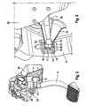
- the pedal unit in the FIGS. 2 and 3 is shown in perspective, for guiding one end 14 of the piston rod 7 a fixed to the brake pedal 4 holding member 13, which has a funnel-shaped, aligned in the direction of the piston rod 7 receptacle 15.
- the receptacle 15 serves to guide the end 14 of the piston rod 7 - here in the form of a piston rod head - during assembly of the pedal unit with the brake booster 1.
- the piston rod 7 after connection with the brake pedal 4 through the receptacle 15 and / or guided by the holding element 13.
- Another advantage is the fact that the brake pedal 4 in the region of the piston rod connection not as in known brake actuation units according to Fig. 1 is weakened.
- Fig. 3 clearly shows, which shows an enlarged and partially cut representation of the pedal unit, the retaining element 13 has a recess 16, at the bottom 17, the end 14 of the piston rod 7 outside the operating mode "brake-by-wire" comes to rest when the distance a is used up to allow a coupling between the brake pedal 4 and the brake booster 1.
- Fig. 3 it is off Fig. 3 can be seen that the funnel-shaped receptacle 15 is fixed to an inner wall 18 of the recess 16.
- the funnel-shaped receptacle 15 on an axial slot 20 and a radial projection 21, which is held under spring tension in an inner groove 22 of the inner wall 18 of the recess 16.
- the inner wall 18 for improved positioning of the receptacle 16 has a step 26 on which the receptacle 16 rests after attachment.
- a damping element 19 is further provided on the bottom 17 of the recess 16, which is preferably formed in the form of a damping ring.
- the retaining element 13 can be fastened to the brake pedal 4 in a simple manner, for example, by welding.
- the invention can in a according Fig. 1 shown and described brake actuation unit with pedal travel simulator 5 and supply and disconnection device 12 find application.
- FIGS. 2 and 3 show the FIGS. 2 and 3 a pedal travel simulator 23 whose force-displacement characteristic is controllably provided. Even with such an embodiment of the brake actuation unit, the invention can be used.
- the control of the force-displacement characteristic, i. the pedal travel is, for example, force-dependent, so that from a predetermined applied to the brake pedal 4 foot force an extension of the pedal travel is made possible and the reaction force applied here does not exceed a defined limit.
- the pedal travel simulator 23 is in this case according to, for example Fig. 2 between a vehicle-fixed component of the pedal unit, the so-called pedal bracket 24, and the brake pedal 4 or a coaxial with the brake pedal 4 rotatable member 25 is arranged in the form of a lever.
Landscapes
- Engineering & Computer Science (AREA)
- Transportation (AREA)
- Mechanical Engineering (AREA)
- Physics & Mathematics (AREA)
- General Physics & Mathematics (AREA)
- Automation & Control Theory (AREA)
- Braking Systems And Boosters (AREA)
- Braking Elements And Transmission Devices (AREA)
- Transmission Of Braking Force In Braking Systems (AREA)
Description
- Die Erfindung betrifft eine Bremsbetätigungseinheit zur Betätigung einer Kraftfahrzeugbremsanlage vom Typ "Brake-by-wire", mit einem sowohl mittels eines Bremspedals als auch mittels einer elektronischen Steuereinheit fahrerwunschabhängig betätigbaren Bremskraftverstärker mit einer Kolbenstange, wobei Mittel zur Entkopplung einer kraftübertragenden Verbindung zwischen dem Bremspedal und dem Bremskraftverstärker in der Betriebsart "Brake-by-wire" vorgesehen sind,
einem dem Bremskraftverstärker nachgeschalteten Hauptbremszylinder, Mitteln zum Erfassen eines Fahrerverzögerungswunsches, sowie einem mit dem Bremspedal zusammenwirkenden Pedalwegsimulator, durch den in der Betriebsart "Brake-by-wire" eine auf das Bremspedal wirkende Rückstellkraft unabhängig von einer Betätigung des Bremskraftverstärkers simulierbar ist, wobei zur Entkopplung zwischen dem Bremspedal bzw. einem dem Bremspedal zugeordneten Bauteil und der Kolbenstange als einem im Kraftfluss nachgeschalteten, dem Bremskraftverstärker zugeordneten Bauteil ein Abstand vorgesehen ist, um das Bremspedal in der Betriebsart "Brake-by-wire" von Rückwirkungskräften der Kraftfahrzeugbremsanlage zu entkoppeln. - Ein derartiges Bremssystem ist aus der
DE 10 2007 044 423 A1 bekannt und findet verbreitet Anwendung in modernen Kraftfahrzeugen mit Hybridantrieb. Die Entkopplung zwischen dem Bremspedal und dem Bremskraftverstärker in der Betriebsart "Brake-by-wire" wird hierbei durch eine Lücke zwischen einem dem Bremspedal zugeordneten Bauteil und einem dem Bremskraftverstärker zugeordneten Bauteil realisiert. Hierzu weist die bekannte Bremsbetätigungseinheit eine Kolbenstange auf, deren Kolbenstangenkopf als ein das Bremspedal umgreifendes, U-förmiges Biegeteil ausgeführt ist. Der Kolbenstangenkopf weist zur Führung eines am Pedal befestigten Bolzens auf beiden Seiten zwei parallel zueinander verlaufende Schenkel auf, in denen Längsführungsöffnungen als durch Stanzen hergestellte Öffnungen ausgebildet sind. Zwischen dem Bolzen und einem Gabelkopfanschlag befindet sich ein axialer Spalt. Dieser stellt beim Rekuperieren, d.h. bei einer Bremsung mittels eines Generators, sicher, dass ein vorgegebener Abstand zum Bremskraftverstärker gehalten wird (Entkopplung). Bei einem Ausfall der Elektronik wird andererseits ein formschlüssiger Kontakt zum Bremskraftverstärker hergestellt. - Ferner ist aus
WO 01/53135 A1 - Als nachteilig werden das aufwendige Design sowie der montagetechnische Mehraufwand der Kolbenstange angesehen.
- Es ist daher Aufgabe der vorliegenden Erfindung, eine dahin gehend verbesserte Bremsbetätigungseinheit vorzuschlagen.
- Diese Aufgabe wird erfindungsgemäß durch die kennzeichnenden Merkmale des unabhängigen Patentanspruchs 1 gelöst. Dabei ist vorgesehen, dass zur Führung eines Endes der Kolbenstange ein Halteelement auf dem Bremspedal befestigt ist, welches eine trichterförmige, in Richtung der Kolbenstange ausgerichtete Aufnahme aufweist. Die Aufnahme dient zum einen der Führung des Endes der Kolbenstange während der Montage der Pedaleinheit mit dem Bremskraftverstärker. Zum anderen wird die Kolbenstange nach Verbindung mit dem Bremspedal durch die Aufnahme und/oder durch das Haltelement geführt.
- Durch die Führung der Kolbenstange mittels der Aufnahme und/oder des Haltelementes ist der axiale Spalt bzw. der Abstand sichergestellt, der in der Betriebsart "Brake-by-wire" eine Entkopplung der kraftübertragenden Verbindung zwischen dem Bremspedal und dem Bremskraftverstärker gewährleistet. Ein weiterer Vorteil ist darin zu sehen, dass das Bremspedal im Bereich der Kolbenstangenverbindung nicht geschwächt wird.
- Weitere Merkmale und Vorteile der Erfindung werden in der nachfolgenden Beschreibung unter Bezugnahme auf die beiliegenden Zeichnungen an einem Ausführungsbeispiel näher erläutert. In den Zeichnungen zeigen schematisch:
- Fig. 1
- eine bekannte Bremsbetätigungseinheit der eingangs genannten Gattung;
- Fig. 2
- eine Pedaleinheit einer erfindungsgemäßen Bremsbetätigungseinheit und
- Fig. 3
- eine vergrößerte Ansicht der Pedaleinheit gemäß
Fig. 2 teilweise geschnitten. - Die in
Fig. 1 dargestellte bekannte Betätigungseinheit besteht aus einem Bremskraftverstärker 1, vorzugsweise einem Unterdruckbremskraftverstärker, einem dem Bremskraftverstärker 1 nachgeschalteten Hauptbremszylinder 2, vorzugsweise einem Tandemhauptzylinder, an dessen nicht dargestellte Druckräume unter Zwischenschaltung einer ebenfalls nicht dargestellten hydraulischen Steuer- und Regeleinheit Radbremsen des Kraftfahrzeuges angeschlossen sind, sowie einem dem Hauptbremszylinder 2 zugeordneten Druckmittelvorratsbehälter 3. Der Betätigung des Bremskraftverstärkers 1 durch den Fahrer dient ein Bremspedal 4, wobei ein mit dem Bremspedal 4 insbesondere in der Betriebsart "Brake-by-wire" zusammenwirkender, lediglich angedeuteter Pedalwegsimulator 5 vorgesehen ist, der dem Fahrer das gewöhnliche Bremspedalgefühl vermittelt. Ein Fahrerverzögerungswunsch bzw. der Betätigungsweg des Bremspedals 4 wird mittels mindestens einer Sensoreinrichtung 6 erfasst, deren Signale einer nicht gezeigten elektronischen Steuereinheit zugeführt werden. Durch die Ausgangssignale der elektronischen Steuereinheit ist u. a. ein dem Bremskraftverstärker 1 zugeordneter Elektromagnet ansteuerbar, der eine vom Fahrerwillen unabhängige Betätigung eines pneumatischen Steuerventils ermöglicht, das eine Luftzufuhr zum Bremskraftverstärker 1 steuert. - Ein mit dem Bremspedal 4 gekoppeltes Eingangsglied bzw. eine Kolbenstange 7, die der Betätigung des vorhin genannten Steuerventils durch den Fahrer dient, weist einen Kolbenstangenkopf 8 auf, in dem Längsführungsöffnungen 9 ausgebildet sind. Die Längsführungsöffnungen 9 nehmen ein mit dem Bremspedal 4 verbundenes Kraftübertragungsteil 10 auf, das als ein Bolzen ausgeführt ist. Dabei ist die Anordnung der genannten Teile 8, 10 derart getroffen, dass zwischen der in der Zeichnung linksseitigen Begrenzung der Längsführungsöffnungen 9 und dem Bolzen 10 ein axialer Spalt bzw. Abstand a vorgesehen ist, der in der Betriebsart "Brake-by-wire" eine Entkopplung der kraftübertragenden Verbindung zwischen dem Bremspedal 4 und dem Bremskraftverstärker 1 gewährleistet. Durch einen zwischen dem Bolzen 10 und der in der Zeichnung linksseitigen Begrenzung der Längsführungsöffnungen 9 vorgesehenen axialen Spalt bzw. Abstand b wird erreicht, dass bei einer vom Fahrerwillen unabhängigen Ansteuerung des Bremskraftverstärkers 1 das Bremspedal 4 nicht mit bewegt wird. Ein Wegsensor 11 dient der Erfassung des Weges einer die Verstärkungskraft des Bremskraftverstärkers 1 aufbringenden beweglichen Wand bzw. des Weges eines Ausgangsglieds des Bremskraftverstärkers 1, das seine Ausgangskraft auf einen nicht dargestellten ersten Kolben des Hauptbremszylinders 2 überträgt.
- Der Pedalwegsimulator 5, durch den, wie bereits erwähnt, in der Betriebsart "Brake-by-wire" eine auf das Bremspedal 4 wirkende Rückstellkraft unabhängig von einer Betätigung des Bremskraftverstärkers 1 simulierbar ist, ist derart ausgeführt, dass er mittels einer lediglich schematisch angedeuteten Zu- und Abschalteinrichtung 12 in der Betriebsart "Brake-by-wire" bei der Entkopplung der kraftübertragenden Verbindung zwischen dem Bremspedal 4 und dem Bremskraftverstärker 1 zuschaltbar und außerhalb der Betriebsart "Brake-by-wire" abschaltbar ist.
- Wie
Fig. 1 weiter zu entnehmen ist, ist der Kolbenstangenkopf 8 als ein das Bremspedal 4 umgreifendes, U-förmiges Biegeteil ausgeführt ist.
Der Kolbenstangenkopf weist zur Führung eines am Pedal befestigten Bolzens auf beiden Seiten zwei parallel zueinander verlaufende Schenkel auf, in denen Längsführungsöffnungen 9 als durch Stanzen hergestellte Öffnungen ausgebildet sind. - Um eine in Hinblick auf das Design sowie den montagetechnischen Aufwand der Kolbenstange verbesserte Bremsbetätigungseinheit bereitzustellen, weist die erfindungsgemäße Bremsbetätigungseinheit, deren Pedaleinheit in den
Fig. 2 und 3 perspektivisch dargestellt ist, zur Führung eines Endes 14 der Kolbenstange 7 ein auf dem Bremspedal 4 befestigtes Halteelement 13 auf, welches eine trichterförmige, in Richtung der Kolbenstange 7 ausgerichtete Aufnahme 15 aufweist. - Die Aufnahme 15 dient zum einen der Führung des Endes 14 der Kolbenstange 7 - hier in Form eines Kolbenstangenkopfes - während der Montage der Pedaleinheit mit dem Bremskraftverstärker 1. Zum anderen wird die Kolbenstange 7 nach Verbindung mit dem Bremspedal 4 durch die Aufnahme 15 und/oder durch das Haltelement 13 geführt.
- Durch die Führung der Kolbenstange 7 mittels der Aufnahme 15 und/oder des Haltelementes 13 ist der axiale Spalt bzw. der Abstand a sichergestellt, der in der Betriebsart "Brake-by-wire" eine Entkopplung der kraftübertragenden Verbindung zwischen dem Bremspedal 4 und dem Bremskraftverstärker 1 gewährleistet.
- Ein weiterer Vorteil ist darin zu sehen, dass das Bremspedal 4 im Bereich der Kolbenstangenverbindung nicht wie bei bekannten Bremsbetätigungseinheiten gemäß
Fig. 1 geschwächt wird. - Wie insbesondere aus
Fig. 3 deutlich hervorgeht, welche eine vergrößerte und teilweise geschnittene Darstellung der Pedaleinheit zeigt, weist das Halteelement 13 eine Ausnehmung 16 auf, an deren Boden 17 das Ende 14 der Kolbenstange 7 außerhalb der Betriebsart "Brake-by-wire" zur Anlage kommt, wenn der Abstand a aufgebraucht wird, um eine Kopplung zwischen dem Bremspedal 4 und dem Bremskraftverstärker 1 zu ermöglichen. - Ferner ist aus
Fig. 3 zu entnehmen, dass die trichterförmige Aufnahme 15 an einer Innenwand 18 der Ausnehmung 16 befestigt ist. Hierzu weist die trichterförmige Aufnahme 15 einen axialen Schlitz 20 und ein radialen Vorsprung 21 auf, welcher unter Federspannung in einer Innennut 22 der Innenwand 18 der Ausnehmung 16 gehalten wird. WieFig. 3 zu entnehmen ist, weist die Innenwand 18 zur verbesserten Positionierung der Aufnahme 16 ein Stufe 26 auf, an welcher die Aufnahme 16 nach der Befestigung anliegt. - Um Geräusche bei Kontakt des Endes 14 mit dem Boden 17 zu reduzieren, ist des Weiteren an dem Boden 17 der Ausnehmung 16 ein Dämpfungselement 19 vorgesehen, welches vorzugsweise in Form eines Dämpfungsringes ausgebildet ist.
- Das Halteelement 13 kann beispielsweise durch Schweißen in einfacher Weise auf dem Bremspedal 4 befestigt werden.
- Die Erfindung kann in einer gemäß
Fig. 1 gezeigten und beschriebenen Bremsbetätigungseinheit mit Pedalwegsimulator 5 und Zu- und Abschalteinrichtung 12 Anwendung finden. - Im Unterschied zu
Fig. 1 zeigen dieFig. 2 und 3 einen Pedalwegsimulator 23, dessen Kraft-Weg-Charakteristik steuerbar vorgesehen ist. Auch bei einer derartigen Ausgestaltung der Bremsbetätigungseinheit kann die Erfindung eingesetzt werden. - Durch die Steuerung der Pedalcharakteristik kann ein zusätzlicher Weg mit limitiertem Kraftniveau freigegeben werden, wenn das "Brake-by-wire"-System ausfällt oder eine höhere Bremsleistung erforderlich ist, so dass keine gesonderte Abschaltung des Pedalwegsimulators 23 in der Rückfallebene gemäß dem beschriebenen Stand der Technik außerhalb der Betriebsart "Brake-by-wire" mehr erfolgen muss. Somit ist besonders von Vorteil, dass keine Einrichtung zur Ab- oder Zuschaltung des Pedalwegsimulators mehr nötig ist, wodurch auch eine Überwachung derselben entfallen kann.
- Die Steuerung der Kraft-Weg-Charakteristik, d.h. des Pedalwegs erfolgt beispielsweise kraftabhängig, so dass ab einer vorbestimmten auf das Bremspedal 4 aufgebrachten Fußkraft eine Verlängerung des Pedalwegs ermöglicht wird und die hierbei aufzubringende Reaktionskraft einen definierten Grenzwert nicht überschreitet.
- Der Pedalwegsimulator 23 ist hierbei beispielsweise gemäß
Fig. 2 zwischen einem fahrzeugfesten Bauteil der Pedaleinheit, dem sogenannten Pedalbock 24, und dem Bremspedal 4 oder einem sich koaxial zum Bremspedal 4 drehbaren Bauteil 25 in Form eines Hebels angeordnet. -
1 Bremskraftverstärker 2 Hauptbremszylinder 3 Druckmittelvorratsbehälter 4 Bremspedal 5 Pedalwegsimulator 6 Sensoreinrichtung 7 Kolbenstange 8 Kolbenstangenkopf 9 Längsführung 10 Kraftübertragungsteil 11 Wegsensor 12 Zu- und Abschalteinrichtung 13 Haltelement 14 Ende 15 Aufnahme 16 Ausnehmung 17 Boden 18 Innenwand 19 Dämpfungselement 20 Schlitz 21 Vorsprung 22 Innennut 23 Pedalwegsimulator 24 Pedalbock 25 Bauteil 26 Stufe a Abstand
Claims (6)
- Bremsbetätigungseinheit zur Betätigung einer Kraftfahrzeugbremsanlage vom Typ "Brake-by-wire", mit einem sowohl mittels eines Bremspedals (4) als auch mittels einer elektronischen Steuereinheit fahrerwunschabhängig betätigbaren Bremskraftverstärker (1) mit einer Kolbenstange (7), wobei Mittel zur Entkopplung einer kraftübertragenden Verbindung zwischen dem Bremspedal (4) und dem Bremskraftverstärker (1) in der Betriebsart "Brake-by-wire" vorgesehen sind,
einem dem Bremskraftverstärker (1) nachgeschalteten Hauptbremszylinder (2),
Mitteln zum Erfassen eines Fahrerverzögerungswunsches (6), sowie
einem mit dem Bremspedal (4) zusammenwirkenden Pedalwegsimulator (5;23), durch den in der Betriebsart "Brake-by-wire" eine auf das Bremspedal (4) wirkende Rückstellkraft unabhängig von einer Betätigung des Bremskraftverstärkers (1) simulierbar ist, wobei zur Entkopplung zwischen dem Bremspedal (4) bzw. einem dem Bremspedal (4) zugeordneten Bauteil und der Kolbenstange (7) als einem im Kraftfluss nachgeschalteten, dem Bremskraftverstärker (1) zugeordneten Bauteil ein Abstand (a) vorgesehen ist, um das Bremspedal (4) in der Betriebsart "Brake-by-wire" von Rückwirkungskräften der Kraftfahrzeugbremsanlage zu entkoppeln,
dadurch gekennzeichnet, dass zur Führung eines Endes (14) der Kolbenstange (7) ein Halteelement (13) auf dem Bremspedal (4) befestigt ist, welches eine trichterförmige, in Richtung der Kolbenstange (7) ausgerichtete Aufnahme (15) aufweist. - Bremsbetätigungseinheit nach Anspruch 1, dadurch gekennzeichnet, dass das Halteelement (13) eine Ausnehmung (16) aufweist, an deren Boden (17) das Ende (14) der Kolbenstange (7) außerhalb der Betriebsart "Brake-by-wire" zur Anlage kommt, und die trichterförmige Aufnahme (15) an einer Innenwand (18) der Ausnehmung (16) befestigt ist.
- Bremsbetätigungseinheit nach Anspruch 2, dadurch gekennzeichnet, dass an dem Boden (17) der Ausnehmung (16) des Halteelementes (13) ein Dämpfungselement (19) vorgesehen ist.
- Bremsbetätigungseinheit nach Anspruch 3, dadurch gekennzeichnet, dass das Dämpfungselement (19) in Form eines Dämpfungsringes vorgesehen ist.
- Bremsbetätigungseinheit nach einem der vorangegangenen Ansprüche, dadurch gekennzeichnet, dass das Halteelement (13) durch Schweißen auf dem Bremspedal (4) befestigt ist.
- Bremsbetätigungseinheit nach einem der vorangegangenen Ansprüche, dadurch gekennzeichnet, dass die trichterförmige Aufnahme (15) einen axialen Schlitz (20) und ein radialen Vorsprung (21) aufweist, wobei der Vorsprung (21) unter Federspannung in einer Innennut (22) der Innenwand der Ausnehmung gehalten wird.
Applications Claiming Priority (3)
| Application Number | Priority Date | Filing Date | Title |
|---|---|---|---|
| DE102009002886 | 2009-05-07 | ||
| DE102010002850A DE102010002850A1 (de) | 2009-05-07 | 2010-03-15 | Bremsbetätigungseinheit zur Betätigung einer Kraftfahrzeugbremsanlage |
| PCT/EP2010/053511 WO2010127898A1 (de) | 2009-05-07 | 2010-03-18 | Bremsbetätigungseinheit zur betätigung einer kraftfahrzeugbremsanlage |
Publications (2)
| Publication Number | Publication Date |
|---|---|
| EP2427355A1 EP2427355A1 (de) | 2012-03-14 |
| EP2427355B1 true EP2427355B1 (de) | 2013-05-29 |
Family
ID=42197726
Family Applications (1)
| Application Number | Title | Priority Date | Filing Date |
|---|---|---|---|
| EP10709518.4A Not-in-force EP2427355B1 (de) | 2009-05-07 | 2010-03-18 | Bremsbetätigungseinheit zur betätigung einer kraftfahrzeugbremsanlage |
Country Status (5)
| Country | Link |
|---|---|
| US (1) | US20120102942A1 (de) |
| EP (1) | EP2427355B1 (de) |
| JP (1) | JP2012526013A (de) |
| DE (1) | DE102010002850A1 (de) |
| WO (1) | WO2010127898A1 (de) |
Families Citing this family (9)
| Publication number | Priority date | Publication date | Assignee | Title |
|---|---|---|---|---|
| DE102011016239A1 (de) * | 2011-04-06 | 2012-10-11 | Volkswagen Ag | Pedalkraftsimulator für eine Fahrzeugbremsanlage |
| DE102014211301B4 (de) | 2013-06-28 | 2017-08-10 | Ford Global Technologies, Llc | Montagehilfe für das Zusammenfügen eines Betätigungshebels und einer Betätigungsstange eines Bremskraftverstärkers |
| US10503200B2 (en) | 2014-05-13 | 2019-12-10 | Ford Global Technologies, Llc | Devices and systems for preventing misalignment in vehicle brake assemblies |
| FR3029494A1 (fr) * | 2014-12-08 | 2016-06-10 | Peugeot Citroen Automobiles Sa | Dispositif et procede d'aide au montage d'une transmission en sortie d'une boite de vitesses d'un groupe motopropulseur pour vehicule automobile |
| FR3057837A1 (fr) * | 2016-10-21 | 2018-04-27 | Peugeot Citroen Automobiles Sa | Systeme de pedale de frein pour un vehicule comportant un freinage automatique |
| US10239531B2 (en) * | 2017-01-10 | 2019-03-26 | GM Global Technology Operations LLC | Fault-tolerant automotive braking system |
| FR3084316B1 (fr) * | 2018-07-27 | 2022-12-09 | Psa Automobiles Sa | Systeme de pedale de frein pour un vehicule comportant un freinage automatique |
| FR3123296B1 (fr) * | 2021-05-27 | 2025-07-11 | Psa Automobiles Sa | Vehicule automobile equipe d’un bloc hydraulique de fonction de controle de trajectoire |
| DE102021129749B4 (de) | 2021-11-15 | 2023-06-22 | Christof Schulte-Göbel | Anströmungsvorrichtung zum Trocknen und/oder Erwärmen eines Werkstücks |
Family Cites Families (12)
| Publication number | Priority date | Publication date | Assignee | Title |
|---|---|---|---|---|
| DE3532769A1 (de) * | 1985-09-13 | 1987-03-19 | Bosch Gmbh Robert | Kugelgelenk fuer einen bremskraftverstaerker |
| DE3677933D1 (de) * | 1986-01-15 | 1991-04-11 | Volkswagen Ag | Betaetigungsvorrichtung mit einem pedal und einer an diesem gelenkig angelenkten druckstange. |
| US5934151A (en) * | 1997-04-18 | 1999-08-10 | General Motors Corporation | Vehicle push rod and pedal assembly |
| DE10002056A1 (de) * | 2000-01-19 | 2001-08-09 | Lucas Varity Gmbh | Bremskrafterzeuger mit verrastbarer Ankopplung an eine Betätigungseinrichtung |
| WO2004005095A1 (de) * | 2002-07-09 | 2004-01-15 | Continental Teves Ag & Co. Ohg | By-wire-bremsbetätigungsvorrichtung |
| FR2860484B1 (fr) * | 2003-10-01 | 2006-01-20 | Bosch Gmbh Robert | Procede de montage d'un dispositif de commande dans un vehicule automobile, dispositif de retenue provisoire pour la mise en oeuvre dudit procede. |
| US7047868B2 (en) * | 2004-01-30 | 2006-05-23 | Fte Automotive Usa Inc. | Piston and cylinder assembly with push rod retention |
| US20080017425A1 (en) * | 2004-04-20 | 2008-01-24 | Continental Teves Ag & Ohg | Process For Operating A Brake Actuation Unit Of A Motor Vehicle Brake System |
| FR2887834B1 (fr) * | 2005-06-30 | 2007-09-28 | Peugeot Citroen Automobiles Sa | Dispositif de liaison pour commande de freinage de vehicule automobile |
| FR2887836B1 (fr) * | 2005-07-01 | 2007-10-12 | Peugeot Citroen Automobiles Sa | Verrou pour solidariser une extremite spherique de commande de frein a un poussoir de pedale de frein de vehicule automobile |
| DE102007044423A1 (de) | 2007-07-04 | 2009-01-15 | Continental Teves Ag & Co. Ohg | Bremskraftverstärker |
| ATE514601T1 (de) * | 2007-08-02 | 2011-07-15 | Continental Teves Ag & Co Ohg | BREMSSYSTEM VOM TYP ßBRAKE-BY-WIREß |
-
2010
- 2010-03-15 DE DE102010002850A patent/DE102010002850A1/de not_active Withdrawn
- 2010-03-18 US US13/318,968 patent/US20120102942A1/en not_active Abandoned
- 2010-03-18 EP EP10709518.4A patent/EP2427355B1/de not_active Not-in-force
- 2010-03-18 JP JP2012508963A patent/JP2012526013A/ja not_active Withdrawn
- 2010-03-18 WO PCT/EP2010/053511 patent/WO2010127898A1/de not_active Ceased
Also Published As
| Publication number | Publication date |
|---|---|
| US20120102942A1 (en) | 2012-05-03 |
| DE102010002850A1 (de) | 2011-08-04 |
| EP2427355A1 (de) | 2012-03-14 |
| WO2010127898A1 (de) | 2010-11-11 |
| JP2012526013A (ja) | 2012-10-25 |
Similar Documents
| Publication | Publication Date | Title |
|---|---|---|
| EP2427355B1 (de) | Bremsbetätigungseinheit zur betätigung einer kraftfahrzeugbremsanlage | |
| EP2097302B1 (de) | Adaptive leerwegreduzierung | |
| EP2985198B1 (de) | Hydraulische bremsanlage mit antiblockier-funktion | |
| EP2563630B1 (de) | Bremsanlage für kraftfahrzeuge | |
| EP2303652B1 (de) | Regelventil für ein fahrzeugbremssystem und fahrzeugbremssystem mit einem solchen regelventil | |
| DE19750977B4 (de) | Bremsanlage | |
| DE102010000882A1 (de) | Bremssystem von Typ "Brake-by-wire" | |
| DE102010043203B4 (de) | Bremskraftverstärker und Verfahren zum Betrieb eines Bremskraftverstärkers | |
| DE102013007574A1 (de) | Betätigungseinrichtung zur Anordnung zwischen einem Bremspedal und einem Hauptbremszylinder eines Kraftfahrzeugs | |
| EP2117894B1 (de) | Bremskraftverstärker | |
| WO2016184609A1 (de) | Elektrohydraulische bremskrafterzeugungsvorrichtung für eine elektro-hydraulische kraftfahrzeug-bremsanlage | |
| DE102020109453A1 (de) | Elektrisch ansteuerbare Betätigungseinheit für eine Kraftfahrzeug-Bremsanlage, Bremskraftverstärker mit einer solchen elektrisch ansteuerbaren Betätigungseinheit und Kraftfahrzeug-Bremsanlage mit einem solchen Bremskraftverstärker | |
| EP2162330B1 (de) | Bremskraftverstärker | |
| EP3380373B1 (de) | Bremsgerät für eine hydraulische kraftfahrzeugbremsanlage | |
| EP2414202B1 (de) | Bremsbetätigungseinheit zur betätigung einer kraftfahrzeugbremsanlage vom typ "brake-by-wire" | |
| DE102006050277A1 (de) | Stufenkolben | |
| DE102022204929B4 (de) | Elektrische feststellbremse | |
| DE102005049199A1 (de) | Bremssystem vom Typ Brake by-wire | |
| DE102004042028A1 (de) | Fahrzeugbremsanlage mit einer Reib- und einer Rekuperationsbremse | |
| EP4412878B1 (de) | Bremsvorrichtung für ein hydraulisches bremssystem eines fahrzeugs und verfahren zum betreiben eines hydraulischen bremssystems eines fahrzeugs | |
| EP2049374B1 (de) | Bremsbetätigungseinheit zur betätigung einer kraftfahrzeugbremsanlage | |
| DE102007005459A1 (de) | Bremskraftverstärker | |
| WO2011113489A1 (de) | Bremsbetätigungseinheit zur betätigung einer kraftfahrzeugbremsanlage | |
| EP1516793B1 (de) | Bremskraftverstärker mit Notbremsassistentfunktion | |
| DE29620694U1 (de) | Elektronisch steuerbarer Bremskraftverstärker |
Legal Events
| Date | Code | Title | Description |
|---|---|---|---|
| PUAI | Public reference made under article 153(3) epc to a published international application that has entered the european phase |
Free format text: ORIGINAL CODE: 0009012 |
|
| 17P | Request for examination filed |
Effective date: 20111207 |
|
| AK | Designated contracting states |
Kind code of ref document: A1 Designated state(s): AT BE BG CH CY CZ DE DK EE ES FI FR GB GR HR HU IE IS IT LI LT LU LV MC MK MT NL NO PL PT RO SE SI SK SM TR |
|
| DAX | Request for extension of the european patent (deleted) | ||
| GRAP | Despatch of communication of intention to grant a patent |
Free format text: ORIGINAL CODE: EPIDOSNIGR1 |
|
| GRAS | Grant fee paid |
Free format text: ORIGINAL CODE: EPIDOSNIGR3 |
|
| GRAA | (expected) grant |
Free format text: ORIGINAL CODE: 0009210 |
|
| AK | Designated contracting states |
Kind code of ref document: B1 Designated state(s): AT BE BG CH CY CZ DE DK EE ES FI FR GB GR HR HU IE IS IT LI LT LU LV MC MK MT NL NO PL PT RO SE SI SK SM TR |
|
| REG | Reference to a national code |
Ref country code: GB Ref legal event code: FG4D Free format text: NOT ENGLISH |
|
| REG | Reference to a national code |
Ref country code: CH Ref legal event code: EP |
|
| REG | Reference to a national code |
Ref country code: AT Ref legal event code: REF Ref document number: 614180 Country of ref document: AT Kind code of ref document: T Effective date: 20130615 |
|
| REG | Reference to a national code |
Ref country code: IE Ref legal event code: FG4D Free format text: LANGUAGE OF EP DOCUMENT: GERMAN |
|
| REG | Reference to a national code |
Ref country code: DE Ref legal event code: R096 Ref document number: 502010003457 Country of ref document: DE Effective date: 20130725 |
|
| REG | Reference to a national code |
Ref country code: LT Ref legal event code: MG4D |
|
| PG25 | Lapsed in a contracting state [announced via postgrant information from national office to epo] |
Ref country code: GR Free format text: LAPSE BECAUSE OF FAILURE TO SUBMIT A TRANSLATION OF THE DESCRIPTION OR TO PAY THE FEE WITHIN THE PRESCRIBED TIME-LIMIT Effective date: 20130830 Ref country code: SE Free format text: LAPSE BECAUSE OF FAILURE TO SUBMIT A TRANSLATION OF THE DESCRIPTION OR TO PAY THE FEE WITHIN THE PRESCRIBED TIME-LIMIT Effective date: 20130529 Ref country code: IS Free format text: LAPSE BECAUSE OF FAILURE TO SUBMIT A TRANSLATION OF THE DESCRIPTION OR TO PAY THE FEE WITHIN THE PRESCRIBED TIME-LIMIT Effective date: 20130929 Ref country code: SI Free format text: LAPSE BECAUSE OF FAILURE TO SUBMIT A TRANSLATION OF THE DESCRIPTION OR TO PAY THE FEE WITHIN THE PRESCRIBED TIME-LIMIT Effective date: 20130529 Ref country code: FI Free format text: LAPSE BECAUSE OF FAILURE TO SUBMIT A TRANSLATION OF THE DESCRIPTION OR TO PAY THE FEE WITHIN THE PRESCRIBED TIME-LIMIT Effective date: 20130529 Ref country code: NO Free format text: LAPSE BECAUSE OF FAILURE TO SUBMIT A TRANSLATION OF THE DESCRIPTION OR TO PAY THE FEE WITHIN THE PRESCRIBED TIME-LIMIT Effective date: 20130829 Ref country code: ES Free format text: LAPSE BECAUSE OF FAILURE TO SUBMIT A TRANSLATION OF THE DESCRIPTION OR TO PAY THE FEE WITHIN THE PRESCRIBED TIME-LIMIT Effective date: 20130909 Ref country code: PT Free format text: LAPSE BECAUSE OF FAILURE TO SUBMIT A TRANSLATION OF THE DESCRIPTION OR TO PAY THE FEE WITHIN THE PRESCRIBED TIME-LIMIT Effective date: 20130930 Ref country code: LT Free format text: LAPSE BECAUSE OF FAILURE TO SUBMIT A TRANSLATION OF THE DESCRIPTION OR TO PAY THE FEE WITHIN THE PRESCRIBED TIME-LIMIT Effective date: 20130529 |
|
| REG | Reference to a national code |
Ref country code: NL Ref legal event code: VDEP Effective date: 20130529 |
|
| PG25 | Lapsed in a contracting state [announced via postgrant information from national office to epo] |
Ref country code: HR Free format text: LAPSE BECAUSE OF FAILURE TO SUBMIT A TRANSLATION OF THE DESCRIPTION OR TO PAY THE FEE WITHIN THE PRESCRIBED TIME-LIMIT Effective date: 20130529 Ref country code: PL Free format text: LAPSE BECAUSE OF FAILURE TO SUBMIT A TRANSLATION OF THE DESCRIPTION OR TO PAY THE FEE WITHIN THE PRESCRIBED TIME-LIMIT Effective date: 20130529 Ref country code: BG Free format text: LAPSE BECAUSE OF FAILURE TO SUBMIT A TRANSLATION OF THE DESCRIPTION OR TO PAY THE FEE WITHIN THE PRESCRIBED TIME-LIMIT Effective date: 20130829 |
|
| PG25 | Lapsed in a contracting state [announced via postgrant information from national office to epo] |
Ref country code: LV Free format text: LAPSE BECAUSE OF FAILURE TO SUBMIT A TRANSLATION OF THE DESCRIPTION OR TO PAY THE FEE WITHIN THE PRESCRIBED TIME-LIMIT Effective date: 20130529 |
|
| PG25 | Lapsed in a contracting state [announced via postgrant information from national office to epo] |
Ref country code: SK Free format text: LAPSE BECAUSE OF FAILURE TO SUBMIT A TRANSLATION OF THE DESCRIPTION OR TO PAY THE FEE WITHIN THE PRESCRIBED TIME-LIMIT Effective date: 20130529 Ref country code: CZ Free format text: LAPSE BECAUSE OF FAILURE TO SUBMIT A TRANSLATION OF THE DESCRIPTION OR TO PAY THE FEE WITHIN THE PRESCRIBED TIME-LIMIT Effective date: 20130529 Ref country code: DK Free format text: LAPSE BECAUSE OF FAILURE TO SUBMIT A TRANSLATION OF THE DESCRIPTION OR TO PAY THE FEE WITHIN THE PRESCRIBED TIME-LIMIT Effective date: 20130529 Ref country code: EE Free format text: LAPSE BECAUSE OF FAILURE TO SUBMIT A TRANSLATION OF THE DESCRIPTION OR TO PAY THE FEE WITHIN THE PRESCRIBED TIME-LIMIT Effective date: 20130529 |
|
| PG25 | Lapsed in a contracting state [announced via postgrant information from national office to epo] |
Ref country code: NL Free format text: LAPSE BECAUSE OF FAILURE TO SUBMIT A TRANSLATION OF THE DESCRIPTION OR TO PAY THE FEE WITHIN THE PRESCRIBED TIME-LIMIT Effective date: 20130529 Ref country code: IT Free format text: LAPSE BECAUSE OF FAILURE TO SUBMIT A TRANSLATION OF THE DESCRIPTION OR TO PAY THE FEE WITHIN THE PRESCRIBED TIME-LIMIT Effective date: 20130529 Ref country code: RO Free format text: LAPSE BECAUSE OF FAILURE TO SUBMIT A TRANSLATION OF THE DESCRIPTION OR TO PAY THE FEE WITHIN THE PRESCRIBED TIME-LIMIT Effective date: 20130529 |
|
| PLBE | No opposition filed within time limit |
Free format text: ORIGINAL CODE: 0009261 |
|
| STAA | Information on the status of an ep patent application or granted ep patent |
Free format text: STATUS: NO OPPOSITION FILED WITHIN TIME LIMIT |
|
| 26N | No opposition filed |
Effective date: 20140303 |
|
| REG | Reference to a national code |
Ref country code: DE Ref legal event code: R097 Ref document number: 502010003457 Country of ref document: DE Effective date: 20140303 |
|
| PG25 | Lapsed in a contracting state [announced via postgrant information from national office to epo] |
Ref country code: LU Free format text: LAPSE BECAUSE OF FAILURE TO SUBMIT A TRANSLATION OF THE DESCRIPTION OR TO PAY THE FEE WITHIN THE PRESCRIBED TIME-LIMIT Effective date: 20140318 |
|
| REG | Reference to a national code |
Ref country code: CH Ref legal event code: PL |
|
| GBPC | Gb: european patent ceased through non-payment of renewal fee |
Effective date: 20140318 |
|
| REG | Reference to a national code |
Ref country code: FR Ref legal event code: ST Effective date: 20141128 |
|
| REG | Reference to a national code |
Ref country code: IE Ref legal event code: MM4A |
|
| PG25 | Lapsed in a contracting state [announced via postgrant information from national office to epo] |
Ref country code: FR Free format text: LAPSE BECAUSE OF NON-PAYMENT OF DUE FEES Effective date: 20140331 Ref country code: LI Free format text: LAPSE BECAUSE OF NON-PAYMENT OF DUE FEES Effective date: 20140331 Ref country code: CH Free format text: LAPSE BECAUSE OF NON-PAYMENT OF DUE FEES Effective date: 20140331 Ref country code: GB Free format text: LAPSE BECAUSE OF NON-PAYMENT OF DUE FEES Effective date: 20140318 Ref country code: IE Free format text: LAPSE BECAUSE OF NON-PAYMENT OF DUE FEES Effective date: 20140318 |
|
| PG25 | Lapsed in a contracting state [announced via postgrant information from national office to epo] |
Ref country code: MT Free format text: LAPSE BECAUSE OF FAILURE TO SUBMIT A TRANSLATION OF THE DESCRIPTION OR TO PAY THE FEE WITHIN THE PRESCRIBED TIME-LIMIT Effective date: 20130529 |
|
| PG25 | Lapsed in a contracting state [announced via postgrant information from national office to epo] |
Ref country code: SM Free format text: LAPSE BECAUSE OF FAILURE TO SUBMIT A TRANSLATION OF THE DESCRIPTION OR TO PAY THE FEE WITHIN THE PRESCRIBED TIME-LIMIT Effective date: 20130529 |
|
| REG | Reference to a national code |
Ref country code: AT Ref legal event code: MM01 Ref document number: 614180 Country of ref document: AT Kind code of ref document: T Effective date: 20150318 |
|
| PG25 | Lapsed in a contracting state [announced via postgrant information from national office to epo] |
Ref country code: MC Free format text: LAPSE BECAUSE OF FAILURE TO SUBMIT A TRANSLATION OF THE DESCRIPTION OR TO PAY THE FEE WITHIN THE PRESCRIBED TIME-LIMIT Effective date: 20130529 |
|
| PG25 | Lapsed in a contracting state [announced via postgrant information from national office to epo] |
Ref country code: CY Free format text: LAPSE BECAUSE OF FAILURE TO SUBMIT A TRANSLATION OF THE DESCRIPTION OR TO PAY THE FEE WITHIN THE PRESCRIBED TIME-LIMIT Effective date: 20130529 |
|
| PG25 | Lapsed in a contracting state [announced via postgrant information from national office to epo] |
Ref country code: HU Free format text: LAPSE BECAUSE OF FAILURE TO SUBMIT A TRANSLATION OF THE DESCRIPTION OR TO PAY THE FEE WITHIN THE PRESCRIBED TIME-LIMIT; INVALID AB INITIO Effective date: 20100318 Ref country code: TR Free format text: LAPSE BECAUSE OF FAILURE TO SUBMIT A TRANSLATION OF THE DESCRIPTION OR TO PAY THE FEE WITHIN THE PRESCRIBED TIME-LIMIT Effective date: 20130529 |
|
| PG25 | Lapsed in a contracting state [announced via postgrant information from national office to epo] |
Ref country code: AT Free format text: LAPSE BECAUSE OF NON-PAYMENT OF DUE FEES Effective date: 20150318 |
|
| PG25 | Lapsed in a contracting state [announced via postgrant information from national office to epo] |
Ref country code: BE Free format text: LAPSE BECAUSE OF NON-PAYMENT OF DUE FEES Effective date: 20140331 |
|
| PG25 | Lapsed in a contracting state [announced via postgrant information from national office to epo] |
Ref country code: MK Free format text: LAPSE BECAUSE OF FAILURE TO SUBMIT A TRANSLATION OF THE DESCRIPTION OR TO PAY THE FEE WITHIN THE PRESCRIBED TIME-LIMIT Effective date: 20130529 |
|
| RIC2 | Information provided on ipc code assigned after grant |
Ipc: B60T 7/06 20060101ALI20101123BHEP Ipc: B60T 11/18 20060101ALI20101123BHEP Ipc: G05G 1/46 20080401ALI20101123BHEP Ipc: B60T 7/04 20060101AFI20101123BHEP |
|
| REG | Reference to a national code |
Ref country code: DE Ref legal event code: R081 Ref document number: 502010003457 Country of ref document: DE Owner name: CONTINENTAL AUTOMOTIVE TECHNOLOGIES GMBH, DE Free format text: FORMER OWNER: CONTINENTAL TEVES AG & CO. OHG, 60488 FRANKFURT, DE |
|
| REG | Reference to a national code |
Ref country code: DE Ref legal event code: R081 Ref document number: 502010003457 Country of ref document: DE Owner name: CONTINENTAL AUTOMOTIVE TECHNOLOGIES GMBH, DE Free format text: FORMER OWNER: CONTINENTAL AUTOMOTIVE TECHNOLOGIES GMBH, 30165 HANNOVER, DE |
|
| PGFP | Annual fee paid to national office [announced via postgrant information from national office to epo] |
Ref country code: DE Payment date: 20240331 Year of fee payment: 15 |
|
| REG | Reference to a national code |
Ref country code: DE Ref legal event code: R119 Ref document number: 502010003457 Country of ref document: DE |
|
| PG25 | Lapsed in a contracting state [announced via postgrant information from national office to epo] |
Ref country code: DE Free format text: LAPSE BECAUSE OF NON-PAYMENT OF DUE FEES Effective date: 20251001 |