EP2428109B1 - Abscheideaggregat für einen Mähdrescher - Google Patents
Abscheideaggregat für einen Mähdrescher Download PDFInfo
- Publication number
- EP2428109B1 EP2428109B1 EP11170517.4A EP11170517A EP2428109B1 EP 2428109 B1 EP2428109 B1 EP 2428109B1 EP 11170517 A EP11170517 A EP 11170517A EP 2428109 B1 EP2428109 B1 EP 2428109B1
- Authority
- EP
- European Patent Office
- Prior art keywords
- crop flow
- separating
- deflecting element
- flow deflecting
- separating device
- Prior art date
- Legal status (The legal status is an assumption and is not a legal conclusion. Google has not performed a legal analysis and makes no representation as to the accuracy of the status listed.)
- Active
Links
Images


Classifications
-
- A—HUMAN NECESSITIES
- A01—AGRICULTURE; FORESTRY; ANIMAL HUSBANDRY; HUNTING; TRAPPING; FISHING
- A01F—PROCESSING OF HARVESTED PRODUCE; HAY OR STRAW PRESSES; DEVICES FOR STORING AGRICULTURAL OR HORTICULTURAL PRODUCE
- A01F7/00—Threshing apparatus
- A01F7/02—Threshing apparatus with rotating tools
- A01F7/06—Threshing apparatus with rotating tools with axles in line with the feeding direction ; Axial threshing machines
Definitions
- the invention relates to a separation unit for a combine harvester according to the preamble of claim 1.
- a separation unit of the type mentioned is from the EP 0 522 267 B1 1 known.
- the deposition unit operating according to the axial flow principle comprises a rotatably mounted separator rotor which is arranged in a housing which comprises at least one separator basket provided with openings, which forms a separation region of the deposition unit, and a cover which has a closed jacket surface.
- the eccentrically arranged lid has on its side facing the separator rotor a plurality of coaxially to the longitudinal axis of the separator rotor spirally juxtaposed guide elements, which extend in sections in the radial direction of the lid.
- a crop stream fed to the separation unit lifts off from the separation rotor and thereby moves along the housing in the axial and radial direction, guided by the separation rotor and the guide elements.
- the residual grains contained in the threshing mat forming on the inner side of the housing are removed in the area of the separating basket.
- the spirally arranged guide elements on the inside of the lid has the task of guiding the crop accelerated by the separation rotor in the circumferential direction to a discharge point.
- the centrifugal forces applied by the separator rotor act equally on the grain to be separated from a crop stream as well as the straw contained in the crop stream. In this case, a compaction effect of the straw can occur at the separation surface of the separating basket, through which a straw mat is formed, which prevents the way in which the grain passes through the straw mat.
- the separation efficiency varies depending on different crop specific as well as separator aggregate specific parameters.
- An increase in the separation efficiency of a previously described deposition unit is based on the increase in the separation area, the increase in the separator rotor speed, the design of the separation baskets and the increase in product cycles in the separation unit.
- the enlargement of the separation surfaces are limited by the limited available space, so that this measure quickly reaches its limits.
- An increase in the Abscheiderot Wegbaum and thus the centrifugal forces is accompanied by an increase in power consumption of the Abscheideaggregates and leads to an increasing destruction of the straw.
- the invention is based on the object to provide a separation unit of the type mentioned, which is characterized by maintaining an existing Abscheide Chemistry by an increased separation efficiency.
- the deposition unit according to the invention can be part of a separation unit with a threshing separation rotor having a threshing area and adjoining separation area in the axial direction of the combine harvester, as well as a combination of a threshing device arranged tangentially to the crop flow direction by the combine to which the threshing unit followed by the axial flow principle working separation unit.
- the at least one Gutstromablenkelement the guide elements in the circumferential direction of the housing is arranged downstream.
- an obstacle-free path is available to the crop stream deflected by the at least one crop flow deflecting element in the radial direction, before it again strikes the surface of the casing surrounding the separating rotor.
- the at least one Gutstromablenkiata at least partially extend over the axial extent of the lateral surface of the lid.
- the axial extent of the arrangement of the at least one Gutstromablenk comprises the axial extent of at least one Abscheidekorbes correspond.
- the crop stream is deflected, at least within the deposition area formed by the at least one separation basket, after each orbit when exiting between the spirally arranged guide elements.
- the arrangement of the at least one Gutstromablenk varieties extends over the entire extent of the deposition region, wherein a continuous or more juxtaposed Gutstromablenk sculpture may be provided.
- the angle of inclination of the at least one ramped Gutstromablenkettis be chosen such that a deflected from the Gutstromablenkelement Gutstrom impinges on the surface of the lid.
- a deflected from the Gutstromablenkelement Gutstrom impinges on the surface of the lid.
- the angle of inclination of the at least one ramp-shaped Gutstromablenkiatas be chosen such that a deflected from the Gutstromablenkelement Gutstrom strikes the surface of the Abscheiderotors. As a result, the product flow is deflected in the direction of the tools of the separator.
- the combing of the tools of the separator rotor with the Erntegutstrom causes the same active mixing, since the flow velocity of the Erntegutstromes is less than the peripheral speed of the tools of the separator rotor.
- the at least one Gutstromablenkelement having a closed surface.
- the at least one Gutstromablenkelement have a partially interrupted surface.
- the advantage of this alternative is that the straw contained in the Erntegutmatte follows the course of the ramp-shaped Gutstromablenkiatas, while the grain contained in the Erntegutmatte may fall through the partially interrupted surface through, to be subsequently deposited on the Abscheidekorb.
- the at least one Gutstromablenkelement have at least one base element for attachment to the inside of the lid, to which a plurality of parallel and spaced from each other arranged rods is mounted.
- a uniform spacing of the rods is provided to each other, but it is also conceivable in the axial direction of the Abscheide Suitees uneven spacing of the rods to each other conceivable.
- the rods may be arranged inclined in the axial and / or radial direction of the rotor at an angle to the surface of the lid. hereby the trajectory of the deflected crop stream can be selectively influenced.
- the Gutstromablenk shame can be detachably fastened to the lid. This allows easy replacement of the Gutstromablenk shame in case of wear as well as the use of different Gutstromablenkiano to perform an adaptation to changing crop conditions can.
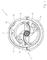
- FIG. 1 is a frontal view of a working according to the Axialpound tac deposition unit 1 of a combine harvester shown.
- the separation unit 1 has a rotatably mounted separation rotor 2 which is surrounded by a housing 3 arranged parallel to the separation rotor 2.
- the housing 3 comprises at least one sieve-like separator basket 4, which forms the separation region of the deposition unit 1, and a cover 5 which, viewed in the circumferential direction, respectively surrounds the deposition rotor 2 approximately in half.
- a plurality of separation baskets 4 are arranged parallel to the longitudinal axis of the separator rotor 2 in the axial direction one behind the other.
- the separator rotor 2 is provided on its peripheral surface 8 with any desired, the peripheral surface 8 spirally spanning carrier elements 9, which provide the crop in the axial Promote the direction of the separation unit 1.
- a possible radial conveying direction of the crop is exemplified by a designated FR arrow, which also corresponds to the direction of rotation of the separator 2.
- the at least one sieve-like separation basket 4 has a multiplicity of passage openings through which grain is separated from a crop stream fed to the separation unit 1.
- the lid 5 has on its the separator rotor 2 facing inside, which is hereinafter referred to as lateral surface 6, a plurality of coaxial with the longitudinal axis of the separator rotor 2 side by side arranged guide elements 7, which extend in sections in the radial direction of the lid 5.
- the guide elements 7 are arranged spirally on the lateral surface 6.
- On the lateral surface 6 of the lid 5 at least one axially parallel to the longitudinal axis of the separator rotor 2 extending, ramped Gutstromablenkelement 10 is arranged.
- the Gutstromablenkelement 10 is arranged downstream of the guide elements 7 in the direction of crop flow or in the direction of rotation of the separator rotor 2 arranged on the outer surface 6.
- the at least one Gutstromablenkelement 10 extends at least almost completely over the entire axial extent of the lateral surface 6.
- the ramp-shaped Gutstromablenkelement 10 has a pitch angle ⁇ , whose size is decisive for the Umlenk of incident on the Gutstromablenkelement 10 crop.
- the crop material fed to the separator rotor 2 after threshing which essentially consists of grain and non-grain components such as straw, is pressed against the jacket surface 6 due to the centrifugal forces due to rotation, forming a compacted crop mat.
- By compacting the Erntegutmatte the passage of the grain contained therein is at least reduced, so that an increase in the separation surfaces formed by the Abscheidekörben 4 has no significant increase in deposition result.
- an increase in the speed of the separator motor is so far not effective, as this is accompanied by an increased energy intake and a larger proportion of destroyed straw.
- the pitch angle ⁇ of the ramp-shaped Gutstromablenkiatas 10 is selected such that the deflected by the Gutstromablenkelement 10 Erntegutmatte meets again after a short flight phase on the outer surface 6. Due to the impact on the lateral surface 6, the Erntegutmatte is segregated and loosened, whereby the grains contained therein in a new circulation in the separator 2 due to the centrifugal forces can move easily through the Erntegutmatte back through to be separated.
- Fig. 2 is a second embodiment of a ramp-shaped Gutstromablenkimplantations 10 'according to Fig. 1 shown.
- the deposition unit 1 has a plurality of deposition baskets 4 arranged one behind the other parallel to the longitudinal axis of the separation rotor 2.
- the Gutstromablenkelement 10 ' differs from the Gutstromablenkelement 10 according to the Fig. 1 in that the pitch angle ⁇ of the ramp-shaped Gutstromablenkettis 10 'is selected to be greater than the pitch angle ⁇ of the Gutstromablenk elements 10 according to Fig.
- the residence time on the ramp-shaped Gutstromablenkiatas 10, 10' is varied to the impact point on the outer surface. 6 to be able to determine the cover 5 or the entry into the area of action of the separator rotor 2.
- FIG. 3 shows a perspective view of the deposition unit 1 according to Fig. 1 with a third embodiment of a Gutstromablenkiatas 20.
- the Gutstromablenkelement 20 is computed or comb-shaped.
- the Gutstromablenkelement 20 has a base member 21 for attachment to the lateral surface 6 of the lid 5.
- a plurality of mutually parallel rods 22 is attached on the base member 21, a plurality of mutually parallel rods 22 is attached.
- the rods 22 are arranged inclined in the radial direction of the separator rotor 2 at a pitch angle ⁇ to the lateral surface 6 of the lid 5, to form a ramp.
- the rods 22 may be arranged inclined in the axial direction of the separator rotor 2 at an angle which approximately corresponds to the inclination angle of the spirally arranged guide elements 7.
- the rake or comb-shaped Gutstromablenkelement 20 combs through the Erntegutmatte and deflects them in accordance with the pitch angle ⁇ , which include the rods 22 and the outer surface 6, in the manner described above.
- the straw contained in the Erntegutmatte is deflected and loosened by Gutstromablenkelement 20, while that the grain contained therein can be at least partially separated from the Erntegutmatte and between the rods on the lateral surface 6 and on the surface of the Separator basket 4 drops.
- the base member 21 may be omitted if the rods 22 would be attached directly to the lateral surface 6.
Landscapes
- Life Sciences & Earth Sciences (AREA)
- Environmental Sciences (AREA)
- Centrifugal Separators (AREA)
- Threshing Machine Elements (AREA)
Description
- Die Erfindung betrifft ein Abscheideaggregat für einen Mähdrescher gemäß dem Oberbegriff des Patentanspruches 1.
- Ein Abscheideaggregat der eingangs genannten Art ist aus der
EP 0 522 267 B1 1 bekannt. Das nach dem Axialflussprinzip arbeitende Abscheideaggregat umfasst einen drehbar gelagerten Abscheiderotor, der in einem Gehäuse angeordnet ist, das mindestens einen mit Öffnungen versehenen Abscheidekorb, der einen Abscheidebereich des Abscheideaggregates bildet, und einen eine geschlossene Mantelfläche aufweisenden Deckel umfasst. Der exzentrisch angeordnete Deckel weist auf seiner dem Abscheiderotor zugewandten Seite eine Vielzahl von koaxial zur Längsachse des Abscheiderotors spiralförmig nebeneinander angeordnete Leitelemente auf, die sich abschnittsweise in radialer Richtung des Deckels erstrecken. Ein dem Abscheideaggregat zugeführter Erntegutstrom hebt auf Grund der Rotationskräfte vom Abscheiderotor ab und bewegt sich dabei, durch den Abscheiderotor und die Leitelemente geführt, in axialer als auch radialer Richtung entlang des Gehäuses. Die in der sich an der Gehäuseinnenseite ausbildenden Dreschmatte enthaltenen Restkörner werden im Bereich des Abscheidekorbes ausgeschieden. Den spiralförmig angeordneten Leitelementen auf der Innenseite des Deckels kommt die Aufgabe zu, das durch den Abscheiderotor in Umfangsrichtung beschleunigte Erntegut zu einer Abgabestelle hin zu leiten. Die von dem Abscheiderotor aufgebrachten Fliehkräfte wirken gleichermaßen auf das aus einem Erntegutstrom abzuscheidende Korn wie auch das in dem Erntegutstrom enthaltene Stroh ein. Dabei kann ein Verdichtungseffekt des Strohs an der Abscheidefläche des Abscheidekorbes auftreten, durch den sich eine Strohmatte ausbildet, die das Ausbeziehungsweise Hindurchtreten des Korns durch die Strohmatte verhindert. - Aus der
US 4,249,543 ist eine nach dem Axialflussprinzip arbeitende Dresch- und Abscheidevorrichtung gemäß dem Oberbegriff des Anspruches 1 bekannt. Gegenstand derUS 4,249,543 ist das Vereinfachen der Wartungsarbeiten, indem eine Rotorzugangseinheit geschaffen wurde, die durch den Rahmen eines Mähdreschers hindurch in das Rotorgehäuse lösbar einführbar ist. - Die Abscheideleistung variiert in Abhängigkeit von verschiedenen erntegutspezifischen wie auch abscheideaggregatspezifischen Parametern. Eine Erhöhung der Abscheideleistung eines zuvor beschriebenen Abscheideaggregates beruht auf der Vergrößerung der Abscheidefläche, der Erhöhung der Abscheiderotordrehzahl, der Ausgestaltung der Abscheidekörbe sowie der Erhöhung von Gutumläufen im Abscheideaggregat. Dabei sind der Vergrößerung der Abscheideflächen durch den nur begrenzt zur Verfügung stehenden Bauraum Grenzen gesetzt, so dass diese Maßnahme schnell an Grenzen stößt. Eine Erhöhung der Abscheiderotordrehzahl und damit der Fliehkräfte geht mit einer Erhöhung der Leistungsaufnahme des Abscheideaggregates einher und führt zu einer zunehmenden Zerstörung des Strohs.
- Der Erfindung liegt die Aufgabe zu Grunde, ein Abscheideaggregat der eingangs genannten Art bereitzustellen, welches sich unter Beibehaltung einer bestehenden Abscheidefläche durch eine erhöhte Abscheideleistung auszeichnet.
- Diese Aufgabe wird durch die im Patentanspruch 1 genannten kennzeichnenden Merkmale gelöst.
- Weitere vorteilhafte Ausführungen des Erfindungsgegenstandes ergeben sich aus den nachgeordneten Unteransprüchen.
- Indem der Erntegutstrom von dem rampenförmigen Gutstromablenkelement von der Oberfläche des Deckels abgehoben und bei seinem anschließenden Wiederauftreffen auf eine den Abscheiderotor umgebende Oberfläche entmischt und aufgelockert wird, wird der weiter oben beschriebene nachteilige Verdichtungseffekt reduziert. Durch den durch das Gutstromablenkelement hervorgerufenen Effekt des Entmischens und Auflockerns des Erntegutstromes lässt sich die erforderliche Abscheiderotordrehzahl reduzieren, was zu einer geringeren Leistungsaufnahme führt sowie mit einer Verbesserung der Strohqualität einhergeht. Ein weiterer Vorteil dieser Anordnung besteht darin, dass der Abscheiderotor zumindest im Bereich des Gutstromablenkelementes nicht aktiv fördert, da sich auf Grund einer exzentrischen Anordnung des Deckels der Erntegutstrom außerhalb des Wirkdurchmessers des Abscheiderotors befindet. Das erfindungsgemäße Abscheideaggregat kann Bestandteil eines Abscheideaggregates mit einem Dresch-Trennrotors sein, der einen sich in axialer Richtung des Mähdreschers Dreschbereich und sich daran anschließenden Abscheidebereich aufweist, wie auch einer Kombination von aus einer tangential zur Gutflussrichtung durch den Mähdrescher angeordneten Drescheinrichtung, an die sich das nach dem Axialflussprinzip arbeitende Abscheideaggregat anschließt.
- Hierzu ist das mindestens eine Gutstromablenkelement den Leitelementen in Umfangsrichtung des Gehäuses gesehen nachgeordnet. Somit steht dem von dem mindestens einen Gutstromablenkelement in radialer Richtung abgelenkten Erntegutstrom eine hindernisfreie Wegstrecke zur Verfügung, bevor es wieder auf die den Abscheiderotor umgebende Oberfläche des Gehäuses auftrifft.
- Insbesondere kann sich das mindestens eine Gutstromablenkelemente zumindest abschnittsweise über die axiale Ausdehnung der Mantelfläche des Deckels erstrecken.
- Vorteilhafterweise kann die axiale Ausdehnung der Anordnung des mindestens einen Gutstromablenkelementes der axialen Ausdehnung zumindest eines Abscheidekorbes entsprechen. Auf diese Weise wird der Erntegutstrom zumindest innerhalb des von dem mindestens einen Abscheidekorb gebildeten Abscheidebereiches nach jedem Umlauf beim Austreten zwischen den spiralförmig angeordneten Leitelementen abgelenkt. Vorzugsweise erstreckt sich die Anordnung des mindestens einen Gutstromablenkelementes über die gesamte Ausdehnung des Abscheidebereiches, wobei ein durchgehendes oder mehrere nebeneinander angeordnete Gutstromablenkelemente vorgesehen sein können.
- Bevorzugt kann der Neigungswinkel des mindestens einen rampenförmigen Gutstromablenkelementes derart gewählt sein, dass ein von dem Gutstromablenkelement abgelenkter Gutstrom auf die Oberfläche des Deckels auftrifft. Durch das gezielte Ablenken des Gutstromes auf die Oberfläche des Deckels kann vermieden werden, dass das abgelenkte Erntegut auf die Oberfläche des mindestens einen Abscheidekorbes auftrifft, um sich zu entmischen, was einen höheren Kurzstrohanteil zur Folge haben würde. Der Einsatz des Gutstromablenkelementes verhält sich in Bezug auf die Belastung der Reinigungseinrichtung im Wesentlichen neutral.
- Gemäß einer bevorzugten Weiterbildung kann der Neigungswinkel des mindestens einen rampenförmigen Gutstromablenkelementes derart gewählt sein, dass ein von dem Gutstromablenkelement abgelenkter Gutstrom auf die Oberfläche des Abscheiderotors trifft. Hierdurch wird der Gutstrom in Richtung der Werkzeuge des Abscheiderotors abgelenkt. Das Kämmen der Werkzeuge des Abscheiderotors mit dem Erntegutstrom bewirkt eine aktive Durchmischung desselben, da die Strömungsgeschwindigkeit des Erntegutstromes geringer als die Umfangsgeschwindigkeit der Werkzeuge des Abscheiderotors ist.
- Vorzugsweise kann das mindestens eine Gutstromablenkelement eine geschlossene Oberfläche aufweisen.
- Alternativ kann das mindestens eine Gutstromablenkelement eine abschnittsweise unterbrochene Oberfläche aufweisen. Der Vorteil dieser Alternative besteht darin, dass das in der Erntegutmatte enthaltene Stroh dem Verlauf des rampenförmigen Gutstromablenkelementes folgt, während das in der Erntegutmatte enthaltene Korn durch die abschnittsweise unterbrochene Oberfläche hindurch fallen kann, um anschließend über den Abscheidekorb abgeschieden zu werden.
- Hierzu kann das mindestens eine Gutstromablenkelement mindestens ein Sockelelement zur Befestigung an der Innenseite des Deckels aufweisen, an welchem eine Vielzahl von parallel und beabstandet zueinander angeordneten Stangen angebracht ist. Vorzugsweise ist eine gleichmäßige Beabstandung der Stangen zueinander vorgesehen, es ist aber auch in axialer Richtung des Abscheidebereiches gesehen eine ungleichmäßige Beabstandung der Stangen zueinander denkbar.
- Insbesondere können die Stangen in axialer und/oder radialer Richtung des Rotors unter einem Winkel zur Oberfläche des Deckels geneigt angeordnet sein. Hierdurch lässt sich die Bewegungsbahn des abgelenkten Erntegutstromes gezielt beeinflussen.
- Vorzugsweise können die Gutstromablenkelemente lösbar an dem Deckel befestigbar sein. Dies ermöglicht den einfachen Austausch der Gutstromablenkelemente bei auftretendem Verschleiß wie auch den Einsatz unterschiedlicher Gutstromablenkelemente, um eine Anpassung an sich verändernde Erntebedingungen durchführen zu können.
- Die Erfindung wird nachstehend anhand von in den Zeichnungen dargestellten Ausführungsbeispielen näher erläutert.
- In den zugehörigen Zeichnungen zeigen:
- Fig. 1
- eine Frontalsicht eines Abscheideaggregates mit einer ersten Ausführungsform eines Gutstromablenkelementes;
- Fig. 2.
- eine perspektivische Ansicht des Abscheideaggregates mit einer zweiten Ausführungsform eines Gutstromablenkelementes gemäß
Fig. 1 ; - Fig. 3.
- eine perspektivische Ansicht des Abscheideaggregates gemäß
Fig. 1 mit einer dritten Ausführungsform eines Gutstromablenkelementes. - In
Fig. 1 ist eine Frontalsicht eines nach dem Axialflussprinzip arbeitenden Abscheideaggregates 1 eines Mähdreschers dargestellt. Das Abscheideaggregat 1 weist einen drehbar gelagerten Abscheiderotor 2 auf, der von einem parallel zu dem Abscheiderotor 2 angeordneten Gehäuse 3 umgeben ist. Das Gehäuse 3 umfasst mindestens einen siebartigen Abscheidekorb 4, der den Abscheidebereich des Abscheideaggregates 1 bildet, sowie einen Deckel 5, die den Abscheidrotor 2 in Umfangsrichtung gesehen jeweils etwa hälftig umgeben. Vorzugsweise sind mehrere Abscheidekörbe 4 parallel zu der Längsachse des Abscheiderotors 2 in axialer Richtung hintereinander liegend angeordnet. Der Abscheiderotor 2 ist auf seiner Umfangsfläche 8 mit beliebig gestalteten, die Umfangsfläche 8 spiralförmig umspannenden Mitnahmeelementen 9 versehen, die das Erntegut in axialer Richtung des Abscheideaggregates 1 fördern. Eine mögliche radiale Förderrichtung des Erntegutes ist beispielhaft durch einen mit FR bezeichneten Pfeil angedeutet, welche auch der Drehrichtung des Abscheiderotors 2 entspricht. - Der mindestens eine siebartige Abscheidekorb 4 weist eine Vielzahl von Durchtrittsöffnungen auf, durch die Korn aus einem dem Abscheideaggregat 1 zugeführten Erntegutstrom abgeschieden wird. Der Deckel 5 weist auf seiner dem Abscheiderotor 2 zugewandten Innenseite, die nachfolgend als Mantelfläche 6 bezeichnet wird, eine Vielzahl von koaxial zur Längsachse des Abscheiderotors 2 nebeneinander angeordneten Leitelementen 7 auf, die sich abschnittsweise in radialer Richtung des Deckels 5 erstrecken. Die Leitelemente 7 sind spiralförmig an der Mantelfläche 6 angeordnet. An der Mantelfläche 6 des Deckels 5 ist mindestens ein sich achsparallel zu der Längsachse des Abscheiderotors 2 erstreckendes, rampenförmiges Gutstromablenkelement 10 angeordnet. Das Gutstromablenkelement 10 ist den Leitelementen 7 in Gutflussrichtung beziehungsweise in Drehrichtung des Abscheiderotors 2 gesehen nachgeordnet auf der Mantelfläche 6 angeordnet. Dabei erstreckt sich das mindestens eine Gutstromablenkelement 10 zumindest nahezu vollständig über die gesamte axiale Ausdehnung der Mantelfläche 6. Das rampenförmige Gutstromablenkelement 10 weist einen Steigungswinkel α auf, dessen Größe für das Umlenkverhalten des auf das Gutstromablenkelement 10 auftreffenden Erntegutes maßgeblich ist.
- Das nach dem Dreschen dem Abscheiderotor 2 zugeführte Erntegut, das sich im Wesentlichen aus Korn und Nichtkornbestandteilen wie Stroh zusammensetzt, wird auf Grund der rotationsbedingten Fliehkräfte an die Mantelfläche 6 gedrückt, wobei sich eine verdichtete Erntegutmatte ausbildet. Durch die Verdichtung der Erntegutmatte wird der Durchgang des darin enthaltenen Korns zumindest reduziert, so dass eine Vergrößerung der von den Abscheidekörben 4 gebildeten Abscheideflächen keine signifikante Zunahme der Abscheidung zur Folge hat. Auch eine Erhöhung der Drehzahl des Abscheiderotors ist insoweit nicht zielführend, da dies mit einer erhöhten Energieaufnahme sowie einem größeren Anteil an zerstörtem Stroh einhergeht. Durch das rampenförmige Gutstromablenkelement 10 an der Mantelfläche 6 wird nach jedem Umlauf des Erntegutes zwischen den jeweiligen Leitelementen 7 die Erntegutmatte entmischt und aufgelockert, indem diese von dem rampenförmigen Gutstromablenkelement 10 von der Mantelfläche 6 abgehoben und anschließend auf diese zurückfällt.
- Der Steigungswinkel α des rampenförmigen Gutstromablenkelementes 10 ist derart gewählt ist, dass die von dem Gutstromablenkelement 10 abgelenkte Erntegutmatte nach einer kurzen Flugphase wieder auf die Mantelfläche 6 trifft. Durch den Aufprall auf die Mantelfläche 6 wird die Erntegutmatte entmischt und aufgelockert, wodurch sich die darin enthaltenen Körner bei einem erneuten Umlauf im Abscheiderotor 2 auf Grund der Fliehkräfte wieder leichter nach außen durch die Erntegutmatte hindurch bewegen können, um abgeschieden zu werden.
- In
Fig. 2 ist eine zweite Ausführungsform eines rampenförmigen Gutstromablenkelementes 10' gemäßFig. 1 dargestellt. Wie der Darstellung zu entnehmen ist, weist das Abscheideaggregat 1 mehrere, parallel zur Längsachse des Abscheiderotors 2 hintereinander angeordnete Abscheidekörbe 4 auf. Das Gutstromablenkelement 10' unterscheidet sich von dem Gutstromablenkelement 10 gemäß derFig. 1 dadurch, dass der Steigungswinkel β des rampenförmigen Gutstromablenkelementes 10' größer gewählt ist als der Steigungswinkel α des Gutstromablenkelementes 10 gemäßFig. 1 . Die Erntegutmatte erfährt auf Grund des größeren Steigungswinkels β eine stärkere Ablenkung, so dass die Erntegutmatte in Richtung des Abscheiderotors 2 abgelenkt wird. Dabei gerät die Erntegutmatte in den Wirkungsbereich der Werkzeuge des Abscheiderotors 2, die diese durchkämmen. Durch das Durchkämmen der Erntegutmatte wird diese aktiv durchmischt, wodurch eine Auflockerung des die Erntegutmatte bildenden Gemisches aus Stroh und Kornbestandteilen erreicht wird. Einen weiteren Aspekt bei der Beeinflussung der Erntegutmatte stellt die Ausdehnung des Gutstromablenkelementes 10, 10' in Umfangsrichtung des Abscheiderotors 2 dar. Mit zunehmender Ausdehnung in radialer Richtung wird die Verweildauer auf dem rampenförmigen Gutstromablenkelementes 10, 10' variiert, um den Auftreffpunkt auf die Mantelfläche 6 des Deckels 5 beziehungsweise den Eintritt in den Wirkungsbereich des Abscheiderotors 2 festlegen zu können. - Die Darstellung in
Fig. 3 zeigt eine perspektivische Ansicht des Abscheideaggregates 1 gemäßFig. 1 mit einer dritten Ausführungsform eines Gutstromablenkelementes 20. Bei dieser Ausführungsform ist das Gutstromablenkelement 20 rechen- oder kammförmig ausgebildet. Hierzu weist das Gutstromablenkelement 20 ein Sockelelement 21 zu der Befestigung an der Mantelfläche 6 des Deckels 5 auf. An dem Sockelelement 21 ist eine Vielzahl von parallel zueinander angeordneten Stangen 22 angebracht. Die Stangen 22 sind in radialer Richtung des Abscheiderotors 2 unter einem Steigungswinkel Φ zu der Mantelfläche 6 des Deckels 5 geneigt angeordnet, um eine Rampe zu bilden. Zudem können die Stangen 22 in axialer Richtung des Abscheiderotors 2 unter einem Winkel geneigt angeordnet sein, der näherungsweise dem Neigungswinkel der spiralförmig angeordneten Leitelemente 7 entspricht. Das rechen- oder kammförmige Gutstromablenkelement 20 durchkämmt die Erntegutmatte und lenkt diese entsprechend des Steigungswinkels Φ, den die Stangen 22 und die Mantelfläche 6 einschließen, in der weiter oben beschriebenen Weise ab. Durch die kamm- oder rechenartige Ausgestaltung wird das in der Erntegutmatte enthaltene Stroh durch das Gutstromablenkelement 20 abgelenkt und aufgelockert, während dass das darin enthaltene Korn zumindest teilweise aus der Erntegutmatte abgeschieden werden kann und zwischen den Stangen hindurch auf die Mantelfläche 6 beziehungsweise auf die Oberfläche des Abscheidekorbes 4 fällt. Das Sockelelement 21 kann entfallen, wenn die Stangen 22 unmittelbar an der Mantelfläche 6 befestigt würden. -
1 Abscheideaggregat 2 Abscheiderotor 3 Gehäuse 4 Abscheidekorb 5 Deckel 6 Mantelfläche 7 Leitelement 8 Umfangsfläche 9 Mitnahmeelemente 10 Gutstromablenkelement 10' Gutstromablenkelement 20 Gutstromablenkelement 21 Sockelelement 22 Stange FR Förderrichtung α Steigungswinkel β Steigungswinkel Φ Steigungswinkel
Claims (11)
- Abscheideaggregat (1) für einen Mähdrescher, welches nach dem Axialflussprinzip arbeitet, umfassend einen drehbar gelagerten Abscheiderotor (2), der in einem Gehäuse (3) angeordnet ist, das mindestens einen mit Öffnungen versehenen Abscheidekorb (4) und einen eine geschlossene Mantelfläche (6) aufweisenden Deckel (5) umfasst, wobei die Mantelfläche (6) auf ihrer dem Abscheiderotor (2) zugewandten Seite eine Vielzahl von koaxial zur Längsachse des Abscheiderotors (2) nebeneinander angeordneten Leitelementen (7) aufweist, die sich abschnittsweise in radialer Richtung des Deckels (5) erstrecken,
dadurch gekennzeichnet,
dass mindestens ein sich achsparallel zu der Längsachse des Abscheiderotors (2) erstreckendes, rampenförmiges Gutstromablenkelement (10, 10', 20) an der dem Abscheiderotor (2) zugewandten Seite der Mantelfläche (6) angeordnet ist, wobei das mindestens eine Gutstromablenkelement (10, 10', 20) den Leitelementen (7) in Umfangsrichtung des Gehäuses (3) gesehen, d.h. in Gutflussrichtung nachgeordnet ist. - Abscheideaggregat (1) nach Anspruch 1, dadurch gekennzeichnet, dass sich das mindestens eine Gutstromablenkelemente (10, 10', 20) zumindest abschnittsweise über die axiale Ausdehnung der Mantelfläche (6) erstreckt.
- Abscheideaggregat (1) nach einem der Ansprüche 1 oder 2, dadurch gekennzeichnet, dass die axiale Ausdehnung der Anordnung des mindestens einen Gutstromablenkelementes (10, 10', 20) der axialen Ausdehnung zumindest eines Abscheidekorbes (4) entspricht.
- Abscheideaggregat (1) nach einem der Ansprüche 1 bis 3 dadurch gekennzeichnet, dass der Steigungswinkel (α, β, Φ) des mindestens einen rampenförmigen Gutstromablenkelementes (10, 10', 20) derart gewählt ist, dass ein von dem Gutstromablenkelement (10, 10', 20) abgelenkter Gutstrom auf den Deckel (5) auftrifft.
- Abscheideaggregat (1) nach einem der Ansprüche 1 bis 3, dadurch gekennzeichnet, dass der Steigungswinkel (α, β, Φ) des mindestens einen rampenförmigen Gutstromablenkelementes (10, 10', 20) derart gewählt ist, dass ein von dem Gutstromablenkelement (10, 10', 20) abgelenkter Gutstrom in den Wirkungsbereich des Abscheiderotors (2) gelangt.
- Abscheideaggregat (1) nach einem der Ansprüche 1 bis 5, dadurch gekennzeichnet, dass durch die radiale Ausdehnung des Gutstromablenkelementes (10, 10', 20) in Umfangsrichtung des Gehäuses (3) variierbar ist.
- Abscheideaggregat (1) nach einem der Ansprüche 1 bis 6, dadurch gekennzeichnet, dass das mindestens eine Gutstromablenkelement (10, 10') eine geschlossene Oberfläche aufweist.
- Abscheideaggregat (1) nach einem der Ansprüche 1 bis 6, dadurch gekennzeichnet, dass das mindestens eine Gutstromablenkelement (20) eine abschnittsweise unterbrochene Oberfläche aufweist.
- Abscheideaggregat (1) nach Anspruch 8, dadurch gekennzeichnet, dass das mindestens eine Gutstromablenkelement (20) mindestens ein Sockelelement (21) zur Befestigung an der Mantelfläche (6) des Deckels (5) aufweist, an welchem eine Vielzahl von parallel zueinander angeordneten Stangen (22) angebracht sind.
- Abscheideaggregat (1) nach Anspruch 9, dadurch gekennzeichnet, dass die Stangen (22) in axialer und/oder radialer Richtung des Abscheiderotors (2) unter einem Winkel zu der Mantelfläche (6) des Deckels (5) geneigt angeordnet sind.
- Abscheideaggregat (1) nach einem der Ansprüche 1 bis 10, dadurch gekennzeichnet, dass die Gutstromablenkelemente (10, 10' ,20) lösbar an dem Deckel (5) befestigbar sind.
Applications Claiming Priority (1)
| Application Number | Priority Date | Filing Date | Title |
|---|---|---|---|
| DE102010037416A DE102010037416A1 (de) | 2010-09-09 | 2010-09-09 | Abscheideaggregat für einen Mähdrescher |
Publications (2)
| Publication Number | Publication Date |
|---|---|
| EP2428109A1 EP2428109A1 (de) | 2012-03-14 |
| EP2428109B1 true EP2428109B1 (de) | 2013-06-12 |
Family
ID=44993978
Family Applications (1)
| Application Number | Title | Priority Date | Filing Date |
|---|---|---|---|
| EP11170517.4A Active EP2428109B1 (de) | 2010-09-09 | 2011-06-20 | Abscheideaggregat für einen Mähdrescher |
Country Status (3)
| Country | Link |
|---|---|
| US (1) | US8251787B2 (de) |
| EP (1) | EP2428109B1 (de) |
| DE (1) | DE102010037416A1 (de) |
Cited By (3)
| Publication number | Priority date | Publication date | Assignee | Title |
|---|---|---|---|---|
| DE202013007813U1 (de) | 2013-09-03 | 2013-09-16 | Franz Heidjann | Abscheidevorrichtung eines Rotor-Mähdreschers |
| EP2936964A1 (de) | 2014-04-24 | 2015-10-28 | CLAAS Selbstfahrende Erntemaschinen GmbH | Abscheideeinrichtung für einen Mähdrescher |
| DE102023117474A1 (de) | 2023-07-03 | 2025-01-09 | Claas Selbstfahrende Erntemaschinen Gmbh | Abscheideaggregat für einen Mähdrescher |
Families Citing this family (4)
| Publication number | Priority date | Publication date | Assignee | Title |
|---|---|---|---|---|
| US8636568B1 (en) * | 2012-07-11 | 2014-01-28 | Cnh America Llc | Combine stepped threshing chamber |
| GB201503118D0 (en) * | 2015-02-25 | 2015-04-08 | Agco Int Gmbh | Twin axial-flow crop processor in a combine harvester |
| US10993375B2 (en) * | 2018-06-19 | 2021-05-04 | Ecomill, Llc | Centrifugal scattering device |
| US11997946B2 (en) | 2019-04-25 | 2024-06-04 | Deere & Company | Access door with integral crop deflector for a combine harvester and method of manufacturing the same |
Family Cites Families (25)
| Publication number | Priority date | Publication date | Assignee | Title |
|---|---|---|---|---|
| US3828793A (en) * | 1973-06-29 | 1974-08-13 | Int Harvester Co | Crop feeding mechanism for axial flow combines |
| US4249543A (en) * | 1979-11-02 | 1981-02-10 | Sperry Corporation | Rotor access module |
| US4611605A (en) * | 1984-08-29 | 1986-09-16 | Deere & Company | Axial flow rotary separator |
| US4739773A (en) * | 1986-05-09 | 1988-04-26 | Deere & Company | Feeding arrangement for an axial flow rotary separator |
| US4875891A (en) * | 1987-03-02 | 1989-10-24 | Deere & Company | Separating grate for a grain harvester |
| DE3932370A1 (de) * | 1989-09-28 | 1991-04-11 | Claas Ohg | Selbstfahrender maehdrescher |
| US5152717A (en) * | 1991-05-10 | 1992-10-06 | Deere & Company | Tooth mounting assembly for axial separator |
| US5112279A (en) * | 1991-05-10 | 1992-05-12 | Deere & Company | Discharge structure for an axial separator |
| US5342239A (en) | 1991-05-10 | 1994-08-30 | Deere & Company | Operation parameters for an axial separator |
| US5334093A (en) * | 1991-05-10 | 1994-08-02 | Deere & Company | Detachable covers for an axial separator |
| US5344367A (en) * | 1993-03-31 | 1994-09-06 | Deere & Company | Infeed plate for an axial agricultural combine |
| AU676037B2 (en) * | 1993-07-01 | 1997-02-27 | Deere & Company | An axial flow combine having a concentric threshing section and an eccentric separation section |
| US5688170A (en) * | 1993-07-01 | 1997-11-18 | Deere & Company | Rotary combine having a concentric infeed section and eccentric threshing and separating sections |
| EP0748583B1 (de) * | 1995-06-17 | 1999-09-15 | CLAAS KGaA | Mähdrescher |
| US6129629A (en) * | 1997-05-27 | 2000-10-10 | Claas Selbstfahrende Erntemaschinen Gmbh | Intake zone for axial separator |
| DE19722793A1 (de) * | 1997-05-30 | 1998-12-03 | Claas Selbstfahr Erntemasch | Mähdrescher |
| US6257977B1 (en) * | 1999-08-20 | 2001-07-10 | Deere & Company | Rotary combine having a rotor axis divergent from a rotor housing axis |
| US6468152B2 (en) * | 2001-03-02 | 2002-10-22 | Deere & Company | Rotary combine having a frusto-conical rotor housing |
| US7070498B2 (en) * | 2003-07-29 | 2006-07-04 | Deere & Company | Frusto-conical drum infeed and threshing region for a combine rotor |
| US20080058042A1 (en) * | 2006-05-25 | 2008-03-06 | Isaac Nathan E | Rigid rotor discharge deflector |
| US7473170B2 (en) * | 2007-02-28 | 2009-01-06 | Cnh America Llc | Off-center pivot, two-bolt vane adjustment for combine harvesters |
| GB0710995D0 (en) * | 2007-06-08 | 2007-07-18 | Agco Do Brasil Com E Ind Stria | Combines |
| US8021219B2 (en) * | 2007-10-31 | 2011-09-20 | Deere And Company | Top cover for axial rotary combine having coned transition |
| US7717777B2 (en) * | 2007-11-29 | 2010-05-18 | Deere & Company | Adjustable rear rotor discharge flights |
| US8075377B2 (en) * | 2007-11-29 | 2011-12-13 | Deere & Company | Rear rotor cone |
-
2010
- 2010-09-09 DE DE102010037416A patent/DE102010037416A1/de not_active Withdrawn
-
2011
- 2011-06-20 EP EP11170517.4A patent/EP2428109B1/de active Active
- 2011-09-07 US US13/226,780 patent/US8251787B2/en not_active Expired - Fee Related
Cited By (6)
| Publication number | Priority date | Publication date | Assignee | Title |
|---|---|---|---|---|
| DE202013007813U1 (de) | 2013-09-03 | 2013-09-16 | Franz Heidjann | Abscheidevorrichtung eines Rotor-Mähdreschers |
| DE102013019680A1 (de) | 2013-09-03 | 2015-03-05 | Franz Heidjann | Abscheidevorrichtung eines Rotor-Mähdreschers |
| EP2936964A1 (de) | 2014-04-24 | 2015-10-28 | CLAAS Selbstfahrende Erntemaschinen GmbH | Abscheideeinrichtung für einen Mähdrescher |
| DE102014105777A1 (de) | 2014-04-24 | 2015-10-29 | Claas Selbstfahrende Erntemaschinen Gmbh | Abscheideeinrichtung für einen Mähdrescher |
| DE102023117474A1 (de) | 2023-07-03 | 2025-01-09 | Claas Selbstfahrende Erntemaschinen Gmbh | Abscheideaggregat für einen Mähdrescher |
| EP4494450A1 (de) | 2023-07-03 | 2025-01-22 | CLAAS Selbstfahrende Erntemaschinen GmbH | Abscheideaggregat für einen mähdrescher |
Also Published As
| Publication number | Publication date |
|---|---|
| US8251787B2 (en) | 2012-08-28 |
| EP2428109A1 (de) | 2012-03-14 |
| US20120064955A1 (en) | 2012-03-15 |
| DE102010037416A1 (de) | 2012-03-15 |
Similar Documents
| Publication | Publication Date | Title |
|---|---|---|
| EP2428109B1 (de) | Abscheideaggregat für einen Mähdrescher | |
| DE2462568C2 (de) | Mähdrescher | |
| EP2537404B1 (de) | Mähdrescher mit einer Axialabscheidevorrichtung und Verfahren zum Betreiben eines Mähdreschers | |
| EP2965614B1 (de) | Einlaufkopfgehäuse | |
| EP2594126B1 (de) | Abscheidekorb | |
| DE69417666T2 (de) | Abrasive Getreide-Bleichmaschine mit einem perforierten zylindrischen Körper zur Entfernung von Kleie | |
| WO2018210657A1 (de) | Siebkugelmühle zur aufbereitung von metallhaltigem grobmaterial | |
| DE2628706A1 (de) | Dreschmaschine, insbesondere maehdrescher | |
| DE2000553B2 (de) | Mähdrescher mit axialem Arbeitsfluß | |
| EP3782454B1 (de) | Mähdrescher mit zuführtrommel und einlaufsegment zur verbesserten gutstromaufteilung in zwei axiale ströme | |
| EP3203829B1 (de) | Vorrichtung zum bearbeiten von erntegut und verfahren zum steuern eines erntegutflusses in der vorrichtung | |
| EP2011384B1 (de) | Erntegutbearbeitungseinheit mit durchsatzabhängiger Umlaufzahl | |
| EP1226747B1 (de) | Leittrommel mit austauschbaren Mitnehmern | |
| DE2943840A1 (de) | Maehdrescher | |
| DE102007062531A1 (de) | Mähdrescher mit Reinigungsgebläse | |
| DE3025380A1 (de) | Maehdrescher | |
| EP3369301B1 (de) | Landwirtschaftliche erntemaschine | |
| DE10062429A1 (de) | Selbstfahrende Erntemaschine | |
| EP3732954B1 (de) | Abscheidevorrichtung | |
| EP1967061B1 (de) | Häcksler und damit ausgestattete Erntemaschine | |
| DE19720074B4 (de) | Mähdrescher | |
| EP1961289A1 (de) | Landwirtschaftliche Arbeitsmaschine | |
| EP4000378B1 (de) | Landwirtschaftliche arbeitsmaschine mit einer trommel | |
| EP1731013B1 (de) | Mulchmähdeck | |
| WO2022129548A1 (de) | Trennvorrichtung, mähdrescher mit einer trennvorrichtung und verfahren zur separierung von beikrautsamen und verlustfrüchten aus dem reinigungsabgang einer erntemaschine |
Legal Events
| Date | Code | Title | Description |
|---|---|---|---|
| AK | Designated contracting states |
Kind code of ref document: A1 Designated state(s): AL AT BE BG CH CY CZ DE DK EE ES FI FR GB GR HR HU IE IS IT LI LT LU LV MC MK MT NL NO PL PT RO RS SE SI SK SM TR |
|
| AX | Request for extension of the european patent |
Extension state: BA ME |
|
| PUAI | Public reference made under article 153(3) epc to a published international application that has entered the european phase |
Free format text: ORIGINAL CODE: 0009012 |
|
| 17P | Request for examination filed |
Effective date: 20120914 |
|
| GRAP | Despatch of communication of intention to grant a patent |
Free format text: ORIGINAL CODE: EPIDOSNIGR1 |
|
| GRAS | Grant fee paid |
Free format text: ORIGINAL CODE: EPIDOSNIGR3 |
|
| GRAA | (expected) grant |
Free format text: ORIGINAL CODE: 0009210 |
|
| AK | Designated contracting states |
Kind code of ref document: B1 Designated state(s): AL AT BE BG CH CY CZ DE DK EE ES FI FR GB GR HR HU IE IS IT LI LT LU LV MC MK MT NL NO PL PT RO RS SE SI SK SM TR |
|
| REG | Reference to a national code |
Ref country code: GB Ref legal event code: FG4D Free format text: NOT ENGLISH |
|
| REG | Reference to a national code |
Ref country code: CH Ref legal event code: EP |
|
| REG | Reference to a national code |
Ref country code: AT Ref legal event code: REF Ref document number: 616308 Country of ref document: AT Kind code of ref document: T Effective date: 20130615 |
|
| REG | Reference to a national code |
Ref country code: IE Ref legal event code: FG4D Free format text: LANGUAGE OF EP DOCUMENT: GERMAN |
|
| REG | Reference to a national code |
Ref country code: DE Ref legal event code: R096 Ref document number: 502011000895 Country of ref document: DE Effective date: 20130808 |
|
| PG25 | Lapsed in a contracting state [announced via postgrant information from national office to epo] |
Ref country code: SE Free format text: LAPSE BECAUSE OF FAILURE TO SUBMIT A TRANSLATION OF THE DESCRIPTION OR TO PAY THE FEE WITHIN THE PRESCRIBED TIME-LIMIT Effective date: 20130612 Ref country code: GR Free format text: LAPSE BECAUSE OF FAILURE TO SUBMIT A TRANSLATION OF THE DESCRIPTION OR TO PAY THE FEE WITHIN THE PRESCRIBED TIME-LIMIT Effective date: 20130913 Ref country code: LT Free format text: LAPSE BECAUSE OF FAILURE TO SUBMIT A TRANSLATION OF THE DESCRIPTION OR TO PAY THE FEE WITHIN THE PRESCRIBED TIME-LIMIT Effective date: 20130612 Ref country code: ES Free format text: LAPSE BECAUSE OF FAILURE TO SUBMIT A TRANSLATION OF THE DESCRIPTION OR TO PAY THE FEE WITHIN THE PRESCRIBED TIME-LIMIT Effective date: 20130923 Ref country code: NO Free format text: LAPSE BECAUSE OF FAILURE TO SUBMIT A TRANSLATION OF THE DESCRIPTION OR TO PAY THE FEE WITHIN THE PRESCRIBED TIME-LIMIT Effective date: 20130912 Ref country code: FI Free format text: LAPSE BECAUSE OF FAILURE TO SUBMIT A TRANSLATION OF THE DESCRIPTION OR TO PAY THE FEE WITHIN THE PRESCRIBED TIME-LIMIT Effective date: 20130612 Ref country code: SI Free format text: LAPSE BECAUSE OF FAILURE TO SUBMIT A TRANSLATION OF THE DESCRIPTION OR TO PAY THE FEE WITHIN THE PRESCRIBED TIME-LIMIT Effective date: 20130612 |
|
| REG | Reference to a national code |
Ref country code: NL Ref legal event code: VDEP Effective date: 20130612 |
|
| REG | Reference to a national code |
Ref country code: LT Ref legal event code: MG4D |
|
| PG25 | Lapsed in a contracting state [announced via postgrant information from national office to epo] |
Ref country code: RS Free format text: LAPSE BECAUSE OF FAILURE TO SUBMIT A TRANSLATION OF THE DESCRIPTION OR TO PAY THE FEE WITHIN THE PRESCRIBED TIME-LIMIT Effective date: 20130612 Ref country code: HR Free format text: LAPSE BECAUSE OF FAILURE TO SUBMIT A TRANSLATION OF THE DESCRIPTION OR TO PAY THE FEE WITHIN THE PRESCRIBED TIME-LIMIT Effective date: 20130612 Ref country code: BG Free format text: LAPSE BECAUSE OF FAILURE TO SUBMIT A TRANSLATION OF THE DESCRIPTION OR TO PAY THE FEE WITHIN THE PRESCRIBED TIME-LIMIT Effective date: 20130912 |
|
| PG25 | Lapsed in a contracting state [announced via postgrant information from national office to epo] |
Ref country code: LV Free format text: LAPSE BECAUSE OF FAILURE TO SUBMIT A TRANSLATION OF THE DESCRIPTION OR TO PAY THE FEE WITHIN THE PRESCRIBED TIME-LIMIT Effective date: 20130612 |
|
| PG25 | Lapsed in a contracting state [announced via postgrant information from national office to epo] |
Ref country code: EE Free format text: LAPSE BECAUSE OF FAILURE TO SUBMIT A TRANSLATION OF THE DESCRIPTION OR TO PAY THE FEE WITHIN THE PRESCRIBED TIME-LIMIT Effective date: 20130612 Ref country code: CZ Free format text: LAPSE BECAUSE OF FAILURE TO SUBMIT A TRANSLATION OF THE DESCRIPTION OR TO PAY THE FEE WITHIN THE PRESCRIBED TIME-LIMIT Effective date: 20130612 Ref country code: SK Free format text: LAPSE BECAUSE OF FAILURE TO SUBMIT A TRANSLATION OF THE DESCRIPTION OR TO PAY THE FEE WITHIN THE PRESCRIBED TIME-LIMIT Effective date: 20130612 Ref country code: IS Free format text: LAPSE BECAUSE OF FAILURE TO SUBMIT A TRANSLATION OF THE DESCRIPTION OR TO PAY THE FEE WITHIN THE PRESCRIBED TIME-LIMIT Effective date: 20131012 Ref country code: PT Free format text: LAPSE BECAUSE OF FAILURE TO SUBMIT A TRANSLATION OF THE DESCRIPTION OR TO PAY THE FEE WITHIN THE PRESCRIBED TIME-LIMIT Effective date: 20131014 |
|
| PG25 | Lapsed in a contracting state [announced via postgrant information from national office to epo] |
Ref country code: PL Free format text: LAPSE BECAUSE OF FAILURE TO SUBMIT A TRANSLATION OF THE DESCRIPTION OR TO PAY THE FEE WITHIN THE PRESCRIBED TIME-LIMIT Effective date: 20130612 Ref country code: RO Free format text: LAPSE BECAUSE OF FAILURE TO SUBMIT A TRANSLATION OF THE DESCRIPTION OR TO PAY THE FEE WITHIN THE PRESCRIBED TIME-LIMIT Effective date: 20130612 Ref country code: NL Free format text: LAPSE BECAUSE OF FAILURE TO SUBMIT A TRANSLATION OF THE DESCRIPTION OR TO PAY THE FEE WITHIN THE PRESCRIBED TIME-LIMIT Effective date: 20130612 |
|
| REG | Reference to a national code |
Ref country code: IE Ref legal event code: MM4A |
|
| PG25 | Lapsed in a contracting state [announced via postgrant information from national office to epo] |
Ref country code: MC Free format text: LAPSE BECAUSE OF FAILURE TO SUBMIT A TRANSLATION OF THE DESCRIPTION OR TO PAY THE FEE WITHIN THE PRESCRIBED TIME-LIMIT Effective date: 20130612 |
|
| PLBE | No opposition filed within time limit |
Free format text: ORIGINAL CODE: 0009261 |
|
| STAA | Information on the status of an ep patent application or granted ep patent |
Free format text: STATUS: NO OPPOSITION FILED WITHIN TIME LIMIT |
|
| PG25 | Lapsed in a contracting state [announced via postgrant information from national office to epo] |
Ref country code: DK Free format text: LAPSE BECAUSE OF FAILURE TO SUBMIT A TRANSLATION OF THE DESCRIPTION OR TO PAY THE FEE WITHIN THE PRESCRIBED TIME-LIMIT Effective date: 20130612 Ref country code: IE Free format text: LAPSE BECAUSE OF NON-PAYMENT OF DUE FEES Effective date: 20130620 |
|
| 26N | No opposition filed |
Effective date: 20140313 |
|
| REG | Reference to a national code |
Ref country code: DE Ref legal event code: R097 Ref document number: 502011000895 Country of ref document: DE Effective date: 20140313 |
|
| REG | Reference to a national code |
Ref country code: CH Ref legal event code: PL |
|
| PG25 | Lapsed in a contracting state [announced via postgrant information from national office to epo] |
Ref country code: MT Free format text: LAPSE BECAUSE OF FAILURE TO SUBMIT A TRANSLATION OF THE DESCRIPTION OR TO PAY THE FEE WITHIN THE PRESCRIBED TIME-LIMIT Effective date: 20130612 |
|
| PG25 | Lapsed in a contracting state [announced via postgrant information from national office to epo] |
Ref country code: LI Free format text: LAPSE BECAUSE OF NON-PAYMENT OF DUE FEES Effective date: 20140630 Ref country code: CH Free format text: LAPSE BECAUSE OF NON-PAYMENT OF DUE FEES Effective date: 20140630 |
|
| PG25 | Lapsed in a contracting state [announced via postgrant information from national office to epo] |
Ref country code: SM Free format text: LAPSE BECAUSE OF FAILURE TO SUBMIT A TRANSLATION OF THE DESCRIPTION OR TO PAY THE FEE WITHIN THE PRESCRIBED TIME-LIMIT Effective date: 20130612 |
|
| PG25 | Lapsed in a contracting state [announced via postgrant information from national office to epo] |
Ref country code: CY Free format text: LAPSE BECAUSE OF FAILURE TO SUBMIT A TRANSLATION OF THE DESCRIPTION OR TO PAY THE FEE WITHIN THE PRESCRIBED TIME-LIMIT Effective date: 20130612 Ref country code: TR Free format text: LAPSE BECAUSE OF FAILURE TO SUBMIT A TRANSLATION OF THE DESCRIPTION OR TO PAY THE FEE WITHIN THE PRESCRIBED TIME-LIMIT Effective date: 20130612 |
|
| PG25 | Lapsed in a contracting state [announced via postgrant information from national office to epo] |
Ref country code: HU Free format text: LAPSE BECAUSE OF FAILURE TO SUBMIT A TRANSLATION OF THE DESCRIPTION OR TO PAY THE FEE WITHIN THE PRESCRIBED TIME-LIMIT; INVALID AB INITIO Effective date: 20110620 Ref country code: MK Free format text: LAPSE BECAUSE OF FAILURE TO SUBMIT A TRANSLATION OF THE DESCRIPTION OR TO PAY THE FEE WITHIN THE PRESCRIBED TIME-LIMIT Effective date: 20130612 Ref country code: LU Free format text: LAPSE BECAUSE OF NON-PAYMENT OF DUE FEES Effective date: 20130620 |
|
| REG | Reference to a national code |
Ref country code: FR Ref legal event code: PLFP Year of fee payment: 6 |
|
| REG | Reference to a national code |
Ref country code: FR Ref legal event code: PLFP Year of fee payment: 7 |
|
| REG | Reference to a national code |
Ref country code: AT Ref legal event code: MM01 Ref document number: 616308 Country of ref document: AT Kind code of ref document: T Effective date: 20160620 |
|
| PG25 | Lapsed in a contracting state [announced via postgrant information from national office to epo] |
Ref country code: AT Free format text: LAPSE BECAUSE OF NON-PAYMENT OF DUE FEES Effective date: 20160620 |
|
| REG | Reference to a national code |
Ref country code: FR Ref legal event code: PLFP Year of fee payment: 8 |
|
| PG25 | Lapsed in a contracting state [announced via postgrant information from national office to epo] |
Ref country code: AL Free format text: LAPSE BECAUSE OF FAILURE TO SUBMIT A TRANSLATION OF THE DESCRIPTION OR TO PAY THE FEE WITHIN THE PRESCRIBED TIME-LIMIT Effective date: 20130612 |
|
| P01 | Opt-out of the competence of the unified patent court (upc) registered |
Effective date: 20230515 |
|
| REG | Reference to a national code |
Ref country code: DE Ref legal event code: R084 Ref document number: 502011000895 Country of ref document: DE |
|
| PGFP | Annual fee paid to national office [announced via postgrant information from national office to epo] |
Ref country code: GB Payment date: 20250618 Year of fee payment: 15 |
|
| PGFP | Annual fee paid to national office [announced via postgrant information from national office to epo] |
Ref country code: BE Payment date: 20250618 Year of fee payment: 15 |
|
| PGFP | Annual fee paid to national office [announced via postgrant information from national office to epo] |
Ref country code: FR Payment date: 20250624 Year of fee payment: 15 |
|
| PGFP | Annual fee paid to national office [announced via postgrant information from national office to epo] |
Ref country code: DE Payment date: 20250618 Year of fee payment: 15 |
|
| PGFP | Annual fee paid to national office [announced via postgrant information from national office to epo] |
Ref country code: IT Payment date: 20250624 Year of fee payment: 15 |