EP2428243B1 - Leckagenventil - Google Patents
Leckagenventil Download PDFInfo
- Publication number
- EP2428243B1 EP2428243B1 EP11007005.9A EP11007005A EP2428243B1 EP 2428243 B1 EP2428243 B1 EP 2428243B1 EP 11007005 A EP11007005 A EP 11007005A EP 2428243 B1 EP2428243 B1 EP 2428243B1
- Authority
- EP
- European Patent Office
- Prior art keywords
- housing
- leakage
- housing part
- leak valve
- connector stub
- Prior art date
- Legal status (The legal status is an assumption and is not a legal conclusion. Google has not performed a legal analysis and makes no representation as to the accuracy of the status listed.)
- Active
Links
Images


Classifications
-
- A—HUMAN NECESSITIES
- A61—MEDICAL OR VETERINARY SCIENCE; HYGIENE
- A61M—DEVICES FOR INTRODUCING MEDIA INTO, OR ONTO, THE BODY; DEVICES FOR TRANSDUCING BODY MEDIA OR FOR TAKING MEDIA FROM THE BODY; DEVICES FOR PRODUCING OR ENDING SLEEP OR STUPOR
- A61M16/00—Devices for influencing the respiratory system of patients by gas treatment, e.g. ventilators; Tracheal tubes
- A61M16/20—Valves specially adapted to medical respiratory devices
- A61M16/208—Non-controlled one-way valves, e.g. exhalation, check, pop-off non-rebreathing valves
-
- A—HUMAN NECESSITIES
- A61—MEDICAL OR VETERINARY SCIENCE; HYGIENE
- A61M—DEVICES FOR INTRODUCING MEDIA INTO, OR ONTO, THE BODY; DEVICES FOR TRANSDUCING BODY MEDIA OR FOR TAKING MEDIA FROM THE BODY; DEVICES FOR PRODUCING OR ENDING SLEEP OR STUPOR
- A61M16/00—Devices for influencing the respiratory system of patients by gas treatment, e.g. ventilators; Tracheal tubes
- A61M16/08—Bellows; Connecting tubes ; Water traps; Patient circuits
-
- A—HUMAN NECESSITIES
- A61—MEDICAL OR VETERINARY SCIENCE; HYGIENE
- A61M—DEVICES FOR INTRODUCING MEDIA INTO, OR ONTO, THE BODY; DEVICES FOR TRANSDUCING BODY MEDIA OR FOR TAKING MEDIA FROM THE BODY; DEVICES FOR PRODUCING OR ENDING SLEEP OR STUPOR
- A61M16/00—Devices for influencing the respiratory system of patients by gas treatment, e.g. ventilators; Tracheal tubes
- A61M16/08—Bellows; Connecting tubes ; Water traps; Patient circuits
- A61M16/0816—Joints or connectors
-
- A—HUMAN NECESSITIES
- A61—MEDICAL OR VETERINARY SCIENCE; HYGIENE
- A61M—DEVICES FOR INTRODUCING MEDIA INTO, OR ONTO, THE BODY; DEVICES FOR TRANSDUCING BODY MEDIA OR FOR TAKING MEDIA FROM THE BODY; DEVICES FOR PRODUCING OR ENDING SLEEP OR STUPOR
- A61M16/00—Devices for influencing the respiratory system of patients by gas treatment, e.g. ventilators; Tracheal tubes
- A61M16/06—Respiratory or anaesthetic masks
-
- A—HUMAN NECESSITIES
- A61—MEDICAL OR VETERINARY SCIENCE; HYGIENE
- A61M—DEVICES FOR INTRODUCING MEDIA INTO, OR ONTO, THE BODY; DEVICES FOR TRANSDUCING BODY MEDIA OR FOR TAKING MEDIA FROM THE BODY; DEVICES FOR PRODUCING OR ENDING SLEEP OR STUPOR
- A61M16/00—Devices for influencing the respiratory system of patients by gas treatment, e.g. ventilators; Tracheal tubes
- A61M16/06—Respiratory or anaesthetic masks
- A61M16/0683—Holding devices therefor
Definitions
- the present invention relates to a leakage valve according to the preamble of claim 1.
- Leakage valves are used in the so-called leakage ventilation.
- the patient to be ventilated receives from a respirator an amount of respiratory gas that is greater than the amount consumed by the patient during respiration. The remainder of this amount of ventilation gas provided by the ventilator leaves the ventilator circuit via the leakage valve.
- the ventilator has a precisely defined delivery rate of respiratory gas. This delivery rate can be adapted to the respective patient-dependent consumption quantities (eg ventilation of an adult or an infant) on the device side.
- Respiratory ventilation ventilators are usually tuned exactly to the amount of leakage established by the leakage valve. If there are fluctuations in the amount of leakage, these are not detected and therefore lead to an undesirable impairment of ventilation, which is particularly important in the ventilation of newborns of particular importance.
- a leakage valve according to the preamble of claim 1 is known.
- the peculiarity of this leakage valve is that a plurality of spacer elements between a base segment and a connection segment are provided, wherein at least one of the spacer elements is designed to achieve a uniform flow guidance as a radial web which extends with respect to a flow longitudinal axis in the radial direction thereto.
- the latching of the inner part with the outer part via at least two spring tabs which engage the front end of the outer part. Inner part and outer part are rotated against each other.
- a certain axial and radial clearance from inner part to outer part is present in such a latching connection, which leads during operation by the mechanical impairment during handling to significant fluctuations in the amount of leakage.
- a leakage valve which also consists of an outer part and a thus latched inner part.
- the inner part has here also spring tabs which engage the front end of the outer part.
- Inner part and outer part should also be consciously rotated against each other here. Again, there is the problem that with mechanical impairment of the leakage valve it comes to significant fluctuations in the amount of leakage.
- the object of the present invention is to provide a novel leak valve which is simple in construction and ensures a reduced fluctuation range of the leak quantity.
- the above object is achieved in the generic leakage valve, characterized in that in the locked state of the two housing parts in addition to the locking connection, a clamping connection is provided and along the circumference of the annular surface a plurality of abutment projections is provided.
- the latching tabs and / or the curved wall areas can be dimensioned in relation to the dimensions of the connection piece in such a way that the latching tabs or wall areas jam with the wall of the connection piece in the latched state of the leakage valve.
- a leakage valve which is both simple in construction and inexpensive to manufacture and ensures effective reduction of the fluctuation of the amount of leakage, especially if in the use of the leakage valve by this example, by head movements of the person to be respirated or the newborn there is a mechanical stress on the connection of the two housing parts.
- the locking connection is thereby simultaneously supported by the clamp connection.
- the presence of the plurality of punctiform introducing abutment abutment along the circumference of the annular surface also leads to an increase in the clamping action in the region of the two housing part gradations and thus to a Reduction of the fluctuation range of the leakage flow under the influence of mechanical forces on the two housing parts.
- the idea ensures that the two housing parts in the latched state without the presence of an axial play of movement together.
- the present invention makes it possible, with a simple structure, to limit the leakage flow of the leakage valve to a maximum fluctuation range of ⁇ 10%, preferably ⁇ 8%, particularly preferably ⁇ 6%, based on a desired leakage quantity.
- the abutment protrusions have a height in the range of 0.1 mm to 0.3 mm.
- a knob-like shape of the plant projections has proven particularly useful here.
- the two housing parts are connected to each other by the latching and supporting clamping connection in such a way that, despite their rotational symmetry in the latched state, they are not rotatable relative to each other about the longitudinal axis of the housing, i. H. counteracts the latching connection and / or clamping connection of a free rotation of the two housing parts to each other.
- an exit slit upstream storage chamber for the leakage flow serves to provide a certain volume of buffer within the leakage valve, whereby fluctuations in the leakage flow can be further reduced.
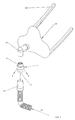
- Reference numeral 1 in Fig. 1 denotes the leakage valve according to the invention. It is positioned on the patient side, for example, as in Fig. 1 represented on the connector 19 of a respiratory mask 18 which is secured by means of straps 20 on the head of the patient or newborn. To connect the leakage valve 4, this has a first connection piece 14 which is inserted into the connection piece 19 of the respiratory mask 18.
- a second connecting piece 4 for connection to a respiratory gas hose 21, which is connected to a respirator (not shown) for generating a respiratory gas flow 22.
- a portion of the breathing gas stream 22 is discharged as leakage current 9 to the outside.
- this is done via an annular exit slit 15 (see. Fig. 2 ).
- a nasal cannula or a tube the latter for so-called invasive ventilation, may also be provided.
- the leakage valve is connected to a so-called "goose gurgel".
- the leakage valve is as in Fig. 2 is shown divided into two parts. It comprises a first housing part 2 and second housing part 3, which are inserted into one another and axially fixed.
- the two housing parts 2, 3 are inserted into each other by appropriately sized curved wall sections 17 and also curved locking tabs 10 on the inner wall of the first connecting piece 4 adjacent enforce this, with a provided at the open end of the locking tab 10 nose 14, the front end of the first connecting piece 4 engages and causes an axial latching.
- the two housing parts 2, 3 are in particular via a first annular surface 6 of the first housing part 2 and the second annular surface 7 of the second housing part 3 viewed in the axial direction against each other.
- the leakage channel is formed by an annular gap formed between the first housing part 2 and the second housing part 3, which opens into an annular circulating stowage chamber 13.
- a circumferential projection 16 protrudes and forms with the adjacent first housing part 2 an annular circumferential outlet gap 15 for a leakage flow.
- the circumferential projection 16 is rounded at its top accordingly. Correspondingly rounded is also the immediately opposite end portion of the first housing part. 2
- the formation and / or dimensioning of the locking tabs 10, the curved wall portions 17 and the inner wall of the first housing part 2 is inventively make such that in addition to the holding action of the locking tabs 10, an additional clamping action is adjusted, which causes the fluctuation of the leakage current even at intense mechanical influence remains substantially constant.
- the two housing parts 2, 3 are in the latched state without axial movement play together.
- the invention makes it possible, for example, the leakage flow of the leakage valve to a maximum fluctuation of ⁇ 4 l / min, preferably ⁇ 2 l / min, based on a desired leakage current amount of z. B. 28-29 l / min lower.
- abutment projections 11 which is a particularly advantageous investment of the two housing parts 2, 3rd guaranteed to each other and even with mechanical influence. These may preferably have a knob-like shape.
- the second housing part 3 is dimensioned by dimensioning the first housing part 2 annular channel portion 12 created between the first housing part 2 and the second housing part 3, which merges into a stowage chamber 13.
- an annular exit gap 15 is formed by a circumferential, curved at the top of the projection 16 and by a lower side, also correspondingly curved end face of the first housing part 2.
- the latching tabs 10 engage around the end-side, upper-side end of the first housing part 2 with their end lugs 14 of the second housing part 2. In this way, an axial latching of the first housing part 2 and the second housing part 3 is achieved. Further, the locking tabs 10 and / or the curved wall portions 17 of the second housing part 3 are dimensioned such that the locking tabs 10 or wall portions 17 jammed in the latched state of the leakage valve 1 with the wall of the connecting piece 4, thus generating an additional clamping connection for locking. The first housing part 2 and second housing part 3 are thereby connected to each other in the latched state almost without axial and / or radial, preferably without any axial and radial play.
- the abutment stops 11 arranged along the circumference help to support this positional fixation, whereby nevertheless a circumferential channel section 12 for the leakage flow is provided between the first housing part 2 and the second housing part 3.
- the leakage flow of the leakage valve according to the invention only has a maximum fluctuation range of 10 l / min, preferably 5 l / min.
- the locking and additional jamming causes the first housing part 2 and the second housing part 3 in the assembled, d. H. latched state due to the clamping action not, at least not with normal force, are rotatable d. H. the locking connection and / or clamping connection counteracts a free rotation of the two housing parts to each other ..
- the invention ensures in the action of mechanical loads on the leakage valve 1, for example due to head movements of the person to be respirated or to be respirated infant or newborn much lower leakage current fluctuations than conventional leakage valves with a comparable simple structure.
- the leakage valve is made of plastic, preferably NAF 21 (DuPont).
Landscapes
- Health & Medical Sciences (AREA)
- Pulmonology (AREA)
- Heart & Thoracic Surgery (AREA)
- Engineering & Computer Science (AREA)
- Anesthesiology (AREA)
- Biomedical Technology (AREA)
- Emergency Medicine (AREA)
- Hematology (AREA)
- Life Sciences & Earth Sciences (AREA)
- Animal Behavior & Ethology (AREA)
- General Health & Medical Sciences (AREA)
- Public Health (AREA)
- Veterinary Medicine (AREA)
- Respiratory Apparatuses And Protective Means (AREA)
Description
- Die vorliegende Erfindung betrifft ein Leckagenventil gemäß dem Oberbegriff des Anspruchs 1.
- Leckagenventile werden bei der sogenannten Leckagenbeatmung eingesetzt. Hierbei bekommt der zu beatmende Patient von einem Beatmungsgerät eine Menge an Beatmungsgas zur Verfügung gestellt, die größer ist als die vom Patienten bei der Atmung verbrauchten Menge. Der Rest dieser vom Beatmungsgerät zur Verfügung gestellten Beatmungsgasmenge verlässt den Beatmungskreis über das Leckagenventil. Bei der Inspiration durchströmt das Beatmungsgas das Innenlumen des Leckagenventils und wäscht zugleich auch alle Reste an verbrachter Luft aus dem Leckagenventil heraus. Das Beatmungsgerät besitzt eine exakt definierte Förderleistung an Beatmungsgas. Diese Förderleistung kann an die betreffenden patientenabhängigen Verbrauchsmengen (z.B. Beatmung eines Erwachsenen oder eines Säuglings) geräteseitig angepasst werden. Beatmungsgeräte zur Leckagenbeatmung sind üblicherweise genau auf die durch das Leckagenventil festgelegte Leckagenmenge abgestimmt. Sofern es zu Schwankungen der Leckagenmenge kommt, werden diese nicht erfasst und führen daher zu einer nicht gewünschten Beeinträchtigung der Beatmung, was insbesondere bei der Beatmung von Neugeborenen von besonderer Wichtigkeit ist.
- Aus der
EP 1 362 610 A1 ist ein Leckagenventil gemäß dem Oberbegriffs des Anspruchs 1 bekannt. Die Besonderheit dieses Leckagenventils besteht darin, dass eine Mehrzahl von Distanzelementen zwischen einem Sockelsegment und einem Anschlusssegment vorgesehen sind, wobei mindestens eines der Distanzelemente zur Erzielung einer gleichmäßigen Strömungsführung als Radialsteg ausgebildet ist, der sich bezüglich einer Strömungslängsachse in radialer Richtung hierzu erstreckt. Die Verrastung des Innenteils mit dem Außenteil erfolgt über mindestens zwei Federlaschen, die im stirnseitigen Ende des Außenteils angreifen. Innenteil und Außenteil sind gegeneinander verdrehbar. Üblicherweise ist jedoch bei einer derartigen Rastverbindung ein gewisses axiales sowie radiales Spiel von Innenteil zu Außenteil vorhanden, welches während des Betriebs durch die mechanische Beeinträchtigung bei der Handhabung zu erheblichen Schwankungen der Leckagenmenge führt. - Aus der
US 5 937 851 ist ein Leckagenventil bekannt, welches ebenfalls aus einem Außenteil sowie einem damit verrastbaren Innenteil besteht. Das Innenteil verfügt auch hier über Federlaschen, die am stirnseitigen Ende des Außenteils angreifen. Innenteil und Außenteil sollen auch hierbei bewusst gegeneinander verdrehbar sein. Auch hier besteht das Problem, dass bei mechanischer Beeinträchtigung des Leckagenventils es zu erheblichen Schwankungen der Leckagenmenge kommt. - Die Aufgabe der vorliegenden Erfindung besteht darin, ein neuartiges Leckagenventil zur Verfügung zu stellen, welches einfach im Aufbau ist und eine reduzierte Schwankungsbreite der Leckagenmenge gewährleistet.
- Die vorstehende Aufgabe wird bei dem gattungsgemäßen Leckagenventil dadurch gelöst, dass im verrasteten Zustand der beiden Gehäuseteile zusätzlich zur Rastverbindung eine Klemmverbindung vorgesehen ist und entlang des Umfangs der Ringfläche eine Mehrzahl von Anlagevorsprüngen vorgesehen ist. Insbesondere können die Rastlaschen und/oder die gekrümmten Wandbereiche in Bezug auf die Abmessungen des Anschlussstutzens derart dimensioniert sein, dass die Rastlaschen bzw. Wandbereiche im verrasteten Zustand des Leckagenventils mit der Wand des Anschlussstutzens verklemmen. Hierdurch wird ein Leckagenventil zur Verfügung gestellt, welches einerseits einfach im Aufbau sowie kostengünstig in der Herstellung ist als auch eine wirksame Reduzierung der Schwankungsbreite der Leckagenmenge gewährleistet, vor allem dann, wenn bei dem Einsatz des Leckagenventils durch an diesem beispielsweise durch Kopfbewegungen der zu beatmenden Person oder des Neugeborenen es zu einer mechanischen Beanspruchung der Verbindung der beiden Gehäuseteile kommt. Die Rastverbindung wird hierdurch gleichzeitig durch die Klemmverbindung unterstützt. Das Vorhandensein der Mehrzahl von die Kraft punktförmig einleitenden Anlagevorsprüngen entlang des Umfangs der Ringfläche führt ebenfalls zu einer Erhöhung der Klemmwirkung im Bereich der beiden Gehäuseteilstufungen und damit zu einer Reduzierung der Schwankungsbreite der Leckageströmung bei Einwirkung mechanischer Kräfte auf die beiden Gehäuseteile.
- Die Idee gewährleistet es, dass die beiden Gehäuseteile im verrasteten Zustand ohne das Vorhandensein eines axialen Bewegungsspiels aneinander liegen.
- Die vorliegende Erfindung ermöglicht es, bei einfachem Aufbau die Leckageströmung des Leckagenventils auf eine maximale Schwankungsbreite ±10 %, vorzugsweise ±8 %, besonders vorzugsweise auf ±6 % bezogen auf eine Soll-Leckagenmenge zu begrenzen.
- Zweckmäßigerweise weisen die Anlagevorsprünge eine Höhe im Bereich von 0,1 mm bis 0,3 mm auf.
- Eine noppenartige Form der Anlagevorsprünge hat sich hierbei besonders bewährt.
- Die beiden Gehäuseteile sind durch die Verrast- und unterstützende Klemmverbindung derart miteinander verbunden, dass sie trotz ihrer Rotationssymmetrie im verrasteten Zustand nicht gegeneinander um die Längsachse des Gehäuses drehbar sind, d. h. die Rastverbindung und/oder Klemmverbindung einer freien Drehbarkeit der beiden Gehäuseteile zueinander entgegenwirkt.
- Die im Bereich des Leckagekanals vorgesehene, einem Austrittsspalt vorgelagerte Staukammer für die Leckageströmung dient dazu, ein gewisses Puffervolumen innerhalb des Leckageventils vorzusehen, wodurch Schwankungen der Leckageströmung zusätzlich verringert werden können.
- Dadurch, dass der Bereich des inneren Gehäuseteils, der Durchgangsöffnungen aufweist, parallel zur Längsachse des Ventilgehäuses verläuft, wird die Herstellbarkeit des Leckageventils vereinfacht.
- Nachstehend wird anhand von Zeichnungsfiguren ein zweckmäßiges Ausführungsbeispiel der Erfindung näher beschrieben. Es zeigen:
- Fig. 1
- eine stark vereinfachte, schematische Darstellung der Positionierung des erfindungsgemäßen Leckagenventils im Einsatz;
- Fig. 2
- eine Teilschnittdarstellung durch eine Ausgestaltung des erfindungsgemäßen Leckagenventils im zusammengesetzten Zustand;
- Fig. 3
- eine Teilschnittdarstellung des ersten und zweiten Gehäuseteils des Leckagenteils nach
Fig. 2 in getrenntem Zustand sowie - Fig. 4
- eine vergrößerte Teilschnittdarstellung des Bereichs des Leckagenkanals des Leckagenteils nach
Fig. 2 . - Bezugsziffer 1 in
Fig. 1 bezeichnet das erfindungsgemäße Leckagenventil. Es ist patientenseitig positioniert, beispielsweise, wie inFig. 1 dargestellt, an dem Anschlussstück 19 einer Beatmungsmaske 18 die mittels Haltebänder 20 am Kopf des Patienten bzw. Neugeborenen befestigt wird. Zum Anschluss des Leckagenventils 4 weist dieses einen ersten Anschlussstutzen 14 auf, der in das Anschlussstück 19 der Beatmungsmaske 18 eingesteckt wird. - An der gegenüberliegenden Seite befindet sich ein zweiter Anschlussstutzen 4 zur Verbindung mit einem Atemgasschlauch 21, der mit einem (nicht dargestellten) Beatmungsgerät (Leckagengerät) zur Erzeugung eines Atemgasstroms 22 verbunden ist.
- Im Leckagenventil 1 wird ein Teil des Atemgasstroms 22 als Leckagenstrom 9 nach außen abgeführt. Bei der Ausgestaltung des Leckagenventils 1 nach
Fig. 1 erfolgt dies über einen ringförmigen Austrittspalt 15 (vgl.Fig. 2 ). Anstelle der Beatmungsmaske 18 kann auch eine Nasenbrille oder ein Tubus, letzterer für eine sogenannte invasive Beatmung, vorgesehen sein. In letzterem Fall wird das Leckagenventil mit einer sog. "Gänsegurgel" verbunden. - Das Leckagenventil ist, wie dies in
Fig. 2 dargestellt ist, zweiteilig aufgeteilt. Es umfasst ein erstes Gehäuseteil 2 sowie zweites Gehäuseteil 3, welche ineinander gesteckt und axial fixiert werden. Die beiden Gehäuseteile 2, 3 werden ineinander gesteckt, indem entsprechend dimensionierte gekrümmte Wandabschnitte 17 sowie ebenfalls gekrümmt ausgebildete Rastlaschen 10 an der Innenwandung des ersten Anschlussstutzens 4 anliegend diesen durchsetzen, wobei eine am offenen Ende der Rastlasche 10 vorgesehenen Nase 14 das stirnseitige Ende des ersten Anschlussstutzens 4 umgreift und eine axiale Verrastung herbeiführt. Die beiden Gehäuseteile 2, 3 liegen insbesondere über eine erste Ringfläche 6 des ersten Gehäuseteils 2 sowie zweite Ringfläche 7 des zweiten Gehäuseteils 3 in Axialrichtung betrachtet aneinander an. - Etwa im Mittelbereich des Leckagenventils 1 befindet sich ein Erweiterungsbereich, gebildet durch einen radialen Vorsprung des ersten Gehäuseteils 2. Etwa in der Höhe dieses Erweiterungsbereichs sind beim zweiten Gehäuseteil 3 Durchgangsöffnungen 8 vorgesehen, die dazu dienen, einen Austritt von Atemgas aus dem Atemgasstrom in den Leckagekanal zu gewährleisten.
- Der Leckagekanal wird durch einen zwischen erstem Gehäuseteil 2 und zweitem Gehäuseteil 3 gebildeten Ringspalt gebildet, der in eine ringförmig umlaufende Staukammer 13 mündet. Unterhalb der Staukammer 13 tritt ein umlaufender Vorsprung 16 hervor und bildet mit dem angrenzenden ersten Gehäuseteil 2 einen ringförmig umlaufenden Austrittsspalt 15 für eine Leckageströmung. Der umlaufende Vorsprung 16 ist an seiner Oberseite entsprechend abgerundet. Entsprechend abgerundet ist auch der unmittelbar gegenüberliegende Endbereich des ersten Gehäuseteils 2.
- Wie aus
Fig. 3 ersichtlich werden die beiden Gehäuseteile 2, 3 mittels der Rastlaschen 10 sowie mittels der gekrümmten Wandbereiche 17 miteinander verbunden. - Die Ausbildung und/oder Dimensionierung der Rastlaschen 10, der gekrümmten Wandbereiche 17 sowie der Innenwandung des ersten Gehäuseteils 2 ist erfindungsgemäß derart vorzunehmen, dass neben der Haltewirkung der Rastlaschen 10 eine zusätzliche Klemmwirkung sich einstellt, die dazu führt, dass die Schwankungsbreite des Leckagenstroms auch bei intensiver mechanischer Einflussnahme im wesentlichen konstant bleibt. Die beiden Gehäuseteile 2, 3 liegen im verrasteten Zustand ohne axialem Bewegungsspiel aneinander.
- Die Erfindung ermöglicht es, die Leckageströmung des Leckageventils beispielsweise auf eine maximale Schwankungsbreite von ±4 l/min, vorzugsweise ±2 l/min, bezogen auf eine Soll-Leckagenstrommenge von z. B. 28-29 l/min zu senken.
- Im Bereich der Ringflächen 6, 7 befinden sich eine Mehrzahl von Anlagevorsprünge 11, die eine besonders vorteilhafte Anlage der beiden Gehäuseteile 2, 3 zueinander und zwar auch bei mechanischer Einflussnahme gewährleistet. Diese können vorzugsweise noppenartige Form aufweisen.
- Wie aus
Fig. 4 ersichtlich bedingen die Anlagevorsprünge 11, die vorzugsweise eine Höhe im Bereich von 0,1 mm bis 0,3 mm aufweisen eine entsprechende Beabstandung der ersten Ringfläche 6 zur zweiten Ringfläche 7. Darüber hinaus wird durch entsprechende Dimensionierung des ersten Gehäuseteils 2 zum zweiten Gehäuseteil 3 ein ringförmiger Kanalabschnitt 12 zwischen erstem Gehäuseteil 2 und zweitem Gehäuseteil 3 geschaffen, welcher in eine Staukammer 13 übergeht. Am Ende der Staukammer 13 befindet sicht ein ringförmiger Austrittsspalt 15, der durch einen umlaufenden, an der Oberseite gekrümmten Vorsprung 16 sowie durch eine unterseitige, ebenfalls entsprechend gekrümmte Stirnfläche des ersten Gehäuseteils 2 gebildet wird. - Aufgrund der Durchgangsöffnungen 8 strömt somit ein Teil des Atemgasstroms 22 aus dem Inneren des Leckagenventils 1 durch die Durchgangsöffnungen 8 hindurch in den Bereich des Kanalabschnitts 12 sowie der Staukammer 13 und von dort durch den ringförmigen Austrittspalt 15 hinaus ins Freie. Die Staukammer 13 wirkt in Verbindung mit dem ringförmigen Austrittspalt 15 eine gewisse Pufferwirkung und damit Vergleichmäßigung des Leckagestroms 9 aus.
- Zur axialen Fixierung umgreifen die Rastlaschen 10 mit ihren endseitigen Nasen 14 des zweiten Gehäuseteils 3 das stirnseitige, oberseitige Ende des ersten Gehäuseteils 2. Hierdurch wird eine axiale Verrastung des ersten Gehäuseteils 2 sowie zweiten Gehäuseteils 3 erzielt. Ferner sind die Rastlaschen 10 und/oder die gekrümmten Wandbereiche 17 des zweiten Gehäuseteils 3 derart dimensioniert, dass die Rastlaschen 10 bzw. Wandbereiche 17 im verrasteten Zustand des Leckagenventils 1 mit der Wand des Anschlussstutzens 4 verklemmen, also eine zur Verrastung zusätzliche Klemmverbindung erzeugen. Das erste Gehäuseteil 2 und zweite Gehäuseteil 3 sind hierdurch im verrasteten Zustand nahezu ohne axiales und/oder radiales, vorzugsweise ohne jegliches axiales und radiales Spiel miteinander verbunden. Im Bereich der ersten Ringfläche 6 sowie zweiten Ringfläche 7 tragen die entlang des Umfangs angeordneten Anlagevorsprünge 11 dazu bei, diese Lagefixierung zu unterstützen, wobei gleichwohl zwischen dem ersten Gehäuseteil 2 sowie zweiten Gehäuseteil 3 ein umlaufender Kanalabschnitt 12 für die Leckagenströmung vorgesehen ist.
- Die Leckageströmung des erfindungsgemäßen Leckageventils weist lediglich eine maximale Schwankungsbreite von 10 l / min, vorzugsweise 5 l / min auf.
- Die Verrastung und zusätzliche Verklemmung führt dazu, dass das erste Gehäuseteil 2 und zweite Gehäuseteil 3 im zusammengesetzten, d. h. verrasteten Zustand aufgrund der Klemmwirkung nicht, zumindest nicht mit normalem Kraftaufwand, drehbar sind d. h. die Rastverbindung und/oder Klemmverbindung einer freien Drehbarkeit der beiden Gehäuseteile zueinander entgegenwirkt..
- Die Erfindung gewährleistet bei im Einwirken von mechanischen Lastungen auf das Leckagenventil 1, beispielsweise bedingt durch Kopfbewegungen der zu beatmenden Person bzw. des zu beatmenden Säuglings bzw. Neugeborenen sehr viel niedrigere Leckagestromschwankungen als bei herkömmlichen Leckageventilen mit vergleichbarem einfachem Aufbau.
- Das Leckagenventil besteht aus Kunststoff, vorzugsweise aus NAF 21 (DuPont).
-
- 1
- Leckagenventil
- 2
- erstes Gehäuseteil
- 3
- zweites Gehäuseteil
- 4
- erster Anschlussstutzen
- 5
- zweiter Anschlussstutzen
- 6
- erste Ringfläche
- 7
- zweite Ringfläche
- 8
- Durchgangsöffnung
- 9
- Leckagestrom
- 10
- Rastlasche
- 11
- Anlagevorsprung
- 12
- Kanalabschnitt
- 13
- Staukammer
- 14
- Nase
- 15
- Austrittsspalt
- 16
- umlaufender Vorsprung
- 17
- gekrümmter Wandbereich
- 18
- Beatmungsmaske
- 19
- Anschlussstück
- 20
- Halteband
- 21
- Atemgasschlauch
- 22
- Atemgasstrom
Claims (6)
- Leckagenventil für den Einsatz in einem Patientenbeatmungssystem mit
einem aus einem ersten (2) und zweiten Gehäuseteil (3) aufgebautem, vorzugsweise aus Kunststoff bestehenden Ventilgehäuse, wobei beide Gehäuseteile einen vorzugsweise im Querschnitt kreisförmigen Fluidkanal bilden und das Ventilgehäuse umfasst:einen ersten Anschlussstutzen (4) am ersten Gehäuseteil (2),einen zweiten Anschlussstutzen (5) am zweiten Gehäuseteil (3) sowieeinen gemeinsamen, radial nach außen vorspringenden Gehäusebereich zwischen den beiden Anschlussstutzen (4, 5),einer im ersten Gehäuseteil vorgesehenen inneren Ringfläche (6), die im verbundenen Zustand der beiden Gehäuseteile (2, 3) einer am zweiten Gehäuseteil vorgesehenen inneren Ringfläche (7) gegenüberliegt,mindestens einer vorzugsweise einer Mehrzahl entlang des Umfangs angeordneter Durchgangsöffnungen (8), die etwa in der Höhe des nach außen vorspringenden Gehäusebereichs angeordnet sind und einen Austritt des Fluids aus dem Fluidkanal in Form einer Leckageströmung ermöglicht bzw. ermöglichen,einem ebenfalls etwa in der Höhe des nach außen vorspringenden Gehäusebereichs angeordneten, zumindest entlang eines Teils vorzugsweise entlang des gesamten Umfangs des Gehäuses umlaufenden, durch beide Gehäuseteile (2, 3) gebildeten ringförmigen Leckagekanals (9) für die Leckageströmung,einem Verrastmechanismus, mittels dem die beiden Gehäuseteile (2, 3) miteinander verbindbar sind,als Rastmechanismus mindestens eine, vorzugsweise einer Mehrzahl von entsprechend dem Innenradius des Anschlussstutzens (4) gekrümmten Rastlaschen (10) mit stirnseitiger Nase (14) vorgesehen sind, die im Zustand der Verrastung sich entlang des Anschlussstutzens (4) innenseitig anliegend erstrecken und mit ihrer Nase (14) an der äußeren Stirnseite des Anschlussstutzen (4 bzw. 5) angreifen und eine axiale Verrastung gewährleisten und zwischen den Rastlaschen (10) entsprechend dem Innenradius des Anschlussstutzens (4) gekrümmte Wandbereiche (17) vorgesehen sind, die an der Innenfläche des Anschlussstutzens (4 bzw. 5) anliegen, wobeiim verrasteten Zustand der beiden Gehäuseteile (2, 3) zusätzlich zur Rastverbindung eine Klemmverbindung vorgesehen ist, dadurch gekennzeichnet, dassentlang des Umfangs der Ringfläche (6 oder 7) eine Mehrzahl von Anlagevorsprüngen (11) vorgesehen ist. - Leckagenventil nach Anspruch 1,
dadurch gekennzeichnet, dass
die beiden Gehäuseteile (2, 3) im verrasteten Zustand ohne axiales Bewegungsspiel aneinanderliegen. - Leckagenventil nach Anspruch 1,
dadurch gekennzeichnet, dass
die Anlagevorsprünge (11) eine Höhe in einem Bereich von 0,1 mm - 0,3 mm aufweisen. - Leckagenventil nach Anspruch 1,
dadurch gekennzeichnet, dass
die Anlagevorsprünge (11) eine noppenartige Form besitzen. - Leckagenventil nach mindestens einem der vorhergehenden Ansprüche,
dadurch gekennzeichnet, dass
im Bereich des Leckagekanals (9) eine Staukammer (13) vorgesehen ist. - Leckagenventil nach mindestens einem der vorhergehenden Ansprüche,
dadurch gekennzeichnet, dass
der Bereich des inneren Gehäuseteils (3), das die Durchgangsöffnungen aufweist, parallel zur Längsachse des Ventilgehäuses verläuft.
Applications Claiming Priority (1)
| Application Number | Priority Date | Filing Date | Title |
|---|---|---|---|
| DE102010045299A DE102010045299A1 (de) | 2010-09-14 | 2010-09-14 | Leckagenventil |
Publications (2)
| Publication Number | Publication Date |
|---|---|
| EP2428243A1 EP2428243A1 (de) | 2012-03-14 |
| EP2428243B1 true EP2428243B1 (de) | 2016-10-12 |
Family
ID=44677323
Family Applications (1)
| Application Number | Title | Priority Date | Filing Date |
|---|---|---|---|
| EP11007005.9A Active EP2428243B1 (de) | 2010-09-14 | 2011-08-27 | Leckagenventil |
Country Status (2)
| Country | Link |
|---|---|
| EP (1) | EP2428243B1 (de) |
| DE (1) | DE102010045299A1 (de) |
Cited By (1)
| Publication number | Priority date | Publication date | Assignee | Title |
|---|---|---|---|---|
| WO2020151827A1 (de) | 2019-01-24 | 2020-07-30 | Wilamed Gmbh | Leckagenventil sowie beatmungsschlauchsystem |
Family Cites Families (6)
| Publication number | Priority date | Publication date | Assignee | Title |
|---|---|---|---|---|
| US5937851A (en) | 1997-02-27 | 1999-08-17 | Respironics, Inc. | Swivel device utilizing bearing clearance to allow carbon dioxide laden exhaust |
| DE10158066A1 (de) * | 2001-11-27 | 2003-06-05 | Weinmann G Geraete Med | Beatmungsmaske |
| EP1362610B1 (de) | 2002-05-14 | 2006-05-17 | Weinmann Geräte für Medizin GmbH & Co. KG | Vorrichtung zur Ableitung von Atemgas |
| DE102004037344A1 (de) * | 2004-08-02 | 2006-03-16 | Map Medizin-Technologie Gmbh | Vorrichtung zur Ableitung von Atemgas aus dem Innenbereich einer Atemmaske, sowie unter Einschluss dieser Vorrichtung gebildete Atemmaskenanordnung |
| DE102005041716B4 (de) * | 2004-09-03 | 2025-06-18 | Löwenstein Medical Technology S.A. | Vorrichtung zur Beatmung |
| DE102007052898B3 (de) * | 2007-11-07 | 2009-04-30 | Dräger Medical AG & Co. KG | Vorrichtung zur Ableitung von Atemgas |
-
2010
- 2010-09-14 DE DE102010045299A patent/DE102010045299A1/de not_active Withdrawn
-
2011
- 2011-08-27 EP EP11007005.9A patent/EP2428243B1/de active Active
Cited By (2)
| Publication number | Priority date | Publication date | Assignee | Title |
|---|---|---|---|---|
| WO2020151827A1 (de) | 2019-01-24 | 2020-07-30 | Wilamed Gmbh | Leckagenventil sowie beatmungsschlauchsystem |
| US12569641B2 (en) | 2019-01-24 | 2026-03-10 | Wilamed Gmbh | Leakage valve and ventilation tube system |
Also Published As
| Publication number | Publication date |
|---|---|
| DE102010045299A1 (de) | 2012-03-15 |
| EP2428243A1 (de) | 2012-03-14 |
Similar Documents
| Publication | Publication Date | Title |
|---|---|---|
| EP0985430B1 (de) | Schalldämpfer für Beatmungsvorrichtungen und Inhalatoren | |
| DE69005086T2 (de) | Sprecheinrichtung zum gebrauch bei sauerstoffversorgung. | |
| DE10126808C1 (de) | Inhalationsmaske | |
| EP2908895B1 (de) | Sprechventil für tracheostomiekanüle | |
| DE102007052898B3 (de) | Vorrichtung zur Ableitung von Atemgas | |
| DE69417439T2 (de) | Zufuhrvorrichtung von sauerstoff und/oder anderen gasen zu einem patienten | |
| DE102012006396A1 (de) | Tracheostomietubus | |
| EP3624883B1 (de) | Exspirationsventil für eine beatmungsvorrichtung mit geräuschminderndem strömungswiderstand | |
| EP1838372A2 (de) | Atemmaske | |
| EP1996268A1 (de) | Vorrichtung zum zuführen von atmungsgas direkt in die nase eines benutzers | |
| DE102017004224A1 (de) | Nasenkanüle für High-Flow-Beatmung | |
| DE102005041717B4 (de) | Atemmaske mit Strömungsleitstrukturen | |
| EP2046431B1 (de) | Tracheostomiekanüle mit innenkanüle | |
| EP2322240B1 (de) | Tracheostomiekanüle mit Fenster | |
| DE19757703C5 (de) | Beatmungsvorrichtung | |
| EP1776153B1 (de) | Vorrichtung zur ableitung von atemgas aus dem innenbereich einer atemmaske, sowie unter einschluss dieser vorrichtung gebildete atemmaskenanordnung an sich | |
| EP2730293B1 (de) | Gasfilter mit Kupfer zum Entfernen von Bakterien und Viren aus einem Gasvolumen | |
| WO2014187511A1 (de) | Atemmaske mit notatemventil | |
| DE29721766U1 (de) | Anschlußstück für die Atemgasversorgung eines Patienten | |
| EP2428243A1 (de) | Leckagenventil | |
| EP3144026B1 (de) | Mehrteilige beatmungsmaske, zugehöriges nasenschlusselement und zugehörige kombination eines schlauchanschlusselements und eines kopplungselements | |
| EP3856314B1 (de) | Leckagenventil sowie beatmungsschlauchsystem | |
| EP4070843B1 (de) | Ausatemsystem und kugelgelenk für eine patientenschnittstelle | |
| EP0911050A2 (de) | Leitungselement für den Anschluss mindestens einer Atemgasleitung für einen Patienten | |
| EP4429743B1 (de) | Ausatemventil |
Legal Events
| Date | Code | Title | Description |
|---|---|---|---|
| AK | Designated contracting states |
Kind code of ref document: A1 Designated state(s): AL AT BE BG CH CY CZ DE DK EE ES FI FR GB GR HR HU IE IS IT LI LT LU LV MC MK MT NL NO PL PT RO RS SE SI SK SM TR |
|
| AX | Request for extension of the european patent |
Extension state: BA ME |
|
| PUAI | Public reference made under article 153(3) epc to a published international application that has entered the european phase |
Free format text: ORIGINAL CODE: 0009012 |
|
| 17P | Request for examination filed |
Effective date: 20120913 |
|
| GRAP | Despatch of communication of intention to grant a patent |
Free format text: ORIGINAL CODE: EPIDOSNIGR1 |
|
| INTG | Intention to grant announced |
Effective date: 20160506 |
|
| GRAS | Grant fee paid |
Free format text: ORIGINAL CODE: EPIDOSNIGR3 |
|
| GRAA | (expected) grant |
Free format text: ORIGINAL CODE: 0009210 |
|
| AK | Designated contracting states |
Kind code of ref document: B1 Designated state(s): AL AT BE BG CH CY CZ DE DK EE ES FI FR GB GR HR HU IE IS IT LI LT LU LV MC MK MT NL NO PL PT RO RS SE SI SK SM TR |
|
| REG | Reference to a national code |
Ref country code: GB Ref legal event code: FG4D Free format text: NOT ENGLISH |
|
| REG | Reference to a national code |
Ref country code: CH Ref legal event code: EP |
|
| REG | Reference to a national code |
Ref country code: AT Ref legal event code: REF Ref document number: 835918 Country of ref document: AT Kind code of ref document: T Effective date: 20161015 |
|
| REG | Reference to a national code |
Ref country code: IE Ref legal event code: FG4D Free format text: LANGUAGE OF EP DOCUMENT: GERMAN |
|
| REG | Reference to a national code |
Ref country code: DE Ref legal event code: R096 Ref document number: 502011010875 Country of ref document: DE |
|
| REG | Reference to a national code |
Ref country code: NL Ref legal event code: FP |
|
| REG | Reference to a national code |
Ref country code: LT Ref legal event code: MG4D |
|
| PG25 | Lapsed in a contracting state [announced via postgrant information from national office to epo] |
Ref country code: LV Free format text: LAPSE BECAUSE OF FAILURE TO SUBMIT A TRANSLATION OF THE DESCRIPTION OR TO PAY THE FEE WITHIN THE PRESCRIBED TIME-LIMIT Effective date: 20161012 |
|
| PG25 | Lapsed in a contracting state [announced via postgrant information from national office to epo] |
Ref country code: NO Free format text: LAPSE BECAUSE OF FAILURE TO SUBMIT A TRANSLATION OF THE DESCRIPTION OR TO PAY THE FEE WITHIN THE PRESCRIBED TIME-LIMIT Effective date: 20170112 Ref country code: LT Free format text: LAPSE BECAUSE OF FAILURE TO SUBMIT A TRANSLATION OF THE DESCRIPTION OR TO PAY THE FEE WITHIN THE PRESCRIBED TIME-LIMIT Effective date: 20161012 Ref country code: SE Free format text: LAPSE BECAUSE OF FAILURE TO SUBMIT A TRANSLATION OF THE DESCRIPTION OR TO PAY THE FEE WITHIN THE PRESCRIBED TIME-LIMIT Effective date: 20161012 Ref country code: GR Free format text: LAPSE BECAUSE OF FAILURE TO SUBMIT A TRANSLATION OF THE DESCRIPTION OR TO PAY THE FEE WITHIN THE PRESCRIBED TIME-LIMIT Effective date: 20170113 |
|
| PG25 | Lapsed in a contracting state [announced via postgrant information from national office to epo] |
Ref country code: HR Free format text: LAPSE BECAUSE OF FAILURE TO SUBMIT A TRANSLATION OF THE DESCRIPTION OR TO PAY THE FEE WITHIN THE PRESCRIBED TIME-LIMIT Effective date: 20161012 Ref country code: IS Free format text: LAPSE BECAUSE OF FAILURE TO SUBMIT A TRANSLATION OF THE DESCRIPTION OR TO PAY THE FEE WITHIN THE PRESCRIBED TIME-LIMIT Effective date: 20170212 Ref country code: FI Free format text: LAPSE BECAUSE OF FAILURE TO SUBMIT A TRANSLATION OF THE DESCRIPTION OR TO PAY THE FEE WITHIN THE PRESCRIBED TIME-LIMIT Effective date: 20161012 Ref country code: ES Free format text: LAPSE BECAUSE OF FAILURE TO SUBMIT A TRANSLATION OF THE DESCRIPTION OR TO PAY THE FEE WITHIN THE PRESCRIBED TIME-LIMIT Effective date: 20161012 Ref country code: RS Free format text: LAPSE BECAUSE OF FAILURE TO SUBMIT A TRANSLATION OF THE DESCRIPTION OR TO PAY THE FEE WITHIN THE PRESCRIBED TIME-LIMIT Effective date: 20161012 Ref country code: PT Free format text: LAPSE BECAUSE OF FAILURE TO SUBMIT A TRANSLATION OF THE DESCRIPTION OR TO PAY THE FEE WITHIN THE PRESCRIBED TIME-LIMIT Effective date: 20170213 Ref country code: PL Free format text: LAPSE BECAUSE OF FAILURE TO SUBMIT A TRANSLATION OF THE DESCRIPTION OR TO PAY THE FEE WITHIN THE PRESCRIBED TIME-LIMIT Effective date: 20161012 |
|
| REG | Reference to a national code |
Ref country code: DE Ref legal event code: R097 Ref document number: 502011010875 Country of ref document: DE |
|
| PG25 | Lapsed in a contracting state [announced via postgrant information from national office to epo] |
Ref country code: EE Free format text: LAPSE BECAUSE OF FAILURE TO SUBMIT A TRANSLATION OF THE DESCRIPTION OR TO PAY THE FEE WITHIN THE PRESCRIBED TIME-LIMIT Effective date: 20161012 Ref country code: CZ Free format text: LAPSE BECAUSE OF FAILURE TO SUBMIT A TRANSLATION OF THE DESCRIPTION OR TO PAY THE FEE WITHIN THE PRESCRIBED TIME-LIMIT Effective date: 20161012 Ref country code: RO Free format text: LAPSE BECAUSE OF FAILURE TO SUBMIT A TRANSLATION OF THE DESCRIPTION OR TO PAY THE FEE WITHIN THE PRESCRIBED TIME-LIMIT Effective date: 20161012 Ref country code: SK Free format text: LAPSE BECAUSE OF FAILURE TO SUBMIT A TRANSLATION OF THE DESCRIPTION OR TO PAY THE FEE WITHIN THE PRESCRIBED TIME-LIMIT Effective date: 20161012 Ref country code: DK Free format text: LAPSE BECAUSE OF FAILURE TO SUBMIT A TRANSLATION OF THE DESCRIPTION OR TO PAY THE FEE WITHIN THE PRESCRIBED TIME-LIMIT Effective date: 20161012 |
|
| PLBE | No opposition filed within time limit |
Free format text: ORIGINAL CODE: 0009261 |
|
| STAA | Information on the status of an ep patent application or granted ep patent |
Free format text: STATUS: NO OPPOSITION FILED WITHIN TIME LIMIT |
|
| REG | Reference to a national code |
Ref country code: FR Ref legal event code: PLFP Year of fee payment: 7 |
|
| PG25 | Lapsed in a contracting state [announced via postgrant information from national office to epo] |
Ref country code: SM Free format text: LAPSE BECAUSE OF FAILURE TO SUBMIT A TRANSLATION OF THE DESCRIPTION OR TO PAY THE FEE WITHIN THE PRESCRIBED TIME-LIMIT Effective date: 20161012 Ref country code: BG Free format text: LAPSE BECAUSE OF FAILURE TO SUBMIT A TRANSLATION OF THE DESCRIPTION OR TO PAY THE FEE WITHIN THE PRESCRIBED TIME-LIMIT Effective date: 20170112 |
|
| 26N | No opposition filed |
Effective date: 20170713 |
|
| PG25 | Lapsed in a contracting state [announced via postgrant information from national office to epo] |
Ref country code: SI Free format text: LAPSE BECAUSE OF FAILURE TO SUBMIT A TRANSLATION OF THE DESCRIPTION OR TO PAY THE FEE WITHIN THE PRESCRIBED TIME-LIMIT Effective date: 20161012 |
|
| REG | Reference to a national code |
Ref country code: CH Ref legal event code: PL |
|
| PG25 | Lapsed in a contracting state [announced via postgrant information from national office to epo] |
Ref country code: MC Free format text: LAPSE BECAUSE OF FAILURE TO SUBMIT A TRANSLATION OF THE DESCRIPTION OR TO PAY THE FEE WITHIN THE PRESCRIBED TIME-LIMIT Effective date: 20161012 |
|
| PG25 | Lapsed in a contracting state [announced via postgrant information from national office to epo] |
Ref country code: LI Free format text: LAPSE BECAUSE OF NON-PAYMENT OF DUE FEES Effective date: 20170831 Ref country code: CH Free format text: LAPSE BECAUSE OF NON-PAYMENT OF DUE FEES Effective date: 20170831 |
|
| REG | Reference to a national code |
Ref country code: IE Ref legal event code: MM4A |
|
| REG | Reference to a national code |
Ref country code: BE Ref legal event code: MM Effective date: 20170831 |
|
| PG25 | Lapsed in a contracting state [announced via postgrant information from national office to epo] |
Ref country code: LU Free format text: LAPSE BECAUSE OF NON-PAYMENT OF DUE FEES Effective date: 20170827 |
|
| PG25 | Lapsed in a contracting state [announced via postgrant information from national office to epo] |
Ref country code: IE Free format text: LAPSE BECAUSE OF NON-PAYMENT OF DUE FEES Effective date: 20170827 |
|
| REG | Reference to a national code |
Ref country code: FR Ref legal event code: PLFP Year of fee payment: 8 |
|
| PG25 | Lapsed in a contracting state [announced via postgrant information from national office to epo] |
Ref country code: BE Free format text: LAPSE BECAUSE OF NON-PAYMENT OF DUE FEES Effective date: 20170831 |
|
| PG25 | Lapsed in a contracting state [announced via postgrant information from national office to epo] |
Ref country code: MT Free format text: LAPSE BECAUSE OF FAILURE TO SUBMIT A TRANSLATION OF THE DESCRIPTION OR TO PAY THE FEE WITHIN THE PRESCRIBED TIME-LIMIT Effective date: 20161012 |
|
| REG | Reference to a national code |
Ref country code: AT Ref legal event code: MM01 Ref document number: 835918 Country of ref document: AT Kind code of ref document: T Effective date: 20170827 |
|
| PG25 | Lapsed in a contracting state [announced via postgrant information from national office to epo] |
Ref country code: AT Free format text: LAPSE BECAUSE OF NON-PAYMENT OF DUE FEES Effective date: 20170827 |
|
| PG25 | Lapsed in a contracting state [announced via postgrant information from national office to epo] |
Ref country code: HU Free format text: LAPSE BECAUSE OF FAILURE TO SUBMIT A TRANSLATION OF THE DESCRIPTION OR TO PAY THE FEE WITHIN THE PRESCRIBED TIME-LIMIT; INVALID AB INITIO Effective date: 20110827 |
|
| PG25 | Lapsed in a contracting state [announced via postgrant information from national office to epo] |
Ref country code: CY Free format text: LAPSE BECAUSE OF NON-PAYMENT OF DUE FEES Effective date: 20161012 |
|
| PG25 | Lapsed in a contracting state [announced via postgrant information from national office to epo] |
Ref country code: MK Free format text: LAPSE BECAUSE OF FAILURE TO SUBMIT A TRANSLATION OF THE DESCRIPTION OR TO PAY THE FEE WITHIN THE PRESCRIBED TIME-LIMIT Effective date: 20161012 |
|
| PG25 | Lapsed in a contracting state [announced via postgrant information from national office to epo] |
Ref country code: TR Free format text: LAPSE BECAUSE OF FAILURE TO SUBMIT A TRANSLATION OF THE DESCRIPTION OR TO PAY THE FEE WITHIN THE PRESCRIBED TIME-LIMIT Effective date: 20161012 |
|
| PG25 | Lapsed in a contracting state [announced via postgrant information from national office to epo] |
Ref country code: AL Free format text: LAPSE BECAUSE OF FAILURE TO SUBMIT A TRANSLATION OF THE DESCRIPTION OR TO PAY THE FEE WITHIN THE PRESCRIBED TIME-LIMIT Effective date: 20161012 |
|
| P01 | Opt-out of the competence of the unified patent court (upc) registered |
Effective date: 20230508 |
|
| REG | Reference to a national code |
Ref country code: DE Ref legal event code: R082 Ref document number: 502011010875 Country of ref document: DE Representative=s name: 4IP GLEIMPETRI PATENT- UND RECHTSANWALTSPARTNE, DE |
|
| PGFP | Annual fee paid to national office [announced via postgrant information from national office to epo] |
Ref country code: NL Payment date: 20250821 Year of fee payment: 15 |
|
| PGFP | Annual fee paid to national office [announced via postgrant information from national office to epo] |
Ref country code: DE Payment date: 20250721 Year of fee payment: 15 |
|
| PGFP | Annual fee paid to national office [announced via postgrant information from national office to epo] |
Ref country code: IT Payment date: 20250829 Year of fee payment: 15 |
|
| PGFP | Annual fee paid to national office [announced via postgrant information from national office to epo] |
Ref country code: GB Payment date: 20250822 Year of fee payment: 15 |
|
| PGFP | Annual fee paid to national office [announced via postgrant information from national office to epo] |
Ref country code: FR Payment date: 20250821 Year of fee payment: 15 |