EP3856314B1 - Leckagenventil sowie beatmungsschlauchsystem - Google Patents
Leckagenventil sowie beatmungsschlauchsystem Download PDFInfo
- Publication number
- EP3856314B1 EP3856314B1 EP19702059.7A EP19702059A EP3856314B1 EP 3856314 B1 EP3856314 B1 EP 3856314B1 EP 19702059 A EP19702059 A EP 19702059A EP 3856314 B1 EP3856314 B1 EP 3856314B1
- Authority
- EP
- European Patent Office
- Prior art keywords
- housing
- leakage
- leakage valve
- housing part
- connection piece
- Prior art date
- Legal status (The legal status is an assumption and is not a legal conclusion. Google has not performed a legal analysis and makes no representation as to the accuracy of the status listed.)
- Active
Links
Images

Classifications
-
- A—HUMAN NECESSITIES
- A61—MEDICAL OR VETERINARY SCIENCE; HYGIENE
- A61M—DEVICES FOR INTRODUCING MEDIA INTO, OR ONTO, THE BODY; DEVICES FOR TRANSDUCING BODY MEDIA OR FOR TAKING MEDIA FROM THE BODY; DEVICES FOR PRODUCING OR ENDING SLEEP OR STUPOR
- A61M16/00—Devices for influencing the respiratory system of patients by gas treatment, e.g. ventilators; Tracheal tubes
- A61M16/08—Bellows; Connecting tubes ; Water traps; Patient circuits
- A61M16/0816—Joints or connectors
- A61M16/0825—Joints or connectors with ball-sockets
-
- A—HUMAN NECESSITIES
- A61—MEDICAL OR VETERINARY SCIENCE; HYGIENE
- A61M—DEVICES FOR INTRODUCING MEDIA INTO, OR ONTO, THE BODY; DEVICES FOR TRANSDUCING BODY MEDIA OR FOR TAKING MEDIA FROM THE BODY; DEVICES FOR PRODUCING OR ENDING SLEEP OR STUPOR
- A61M16/00—Devices for influencing the respiratory system of patients by gas treatment, e.g. ventilators; Tracheal tubes
- A61M16/08—Bellows; Connecting tubes ; Water traps; Patient circuits
- A61M16/0816—Joints or connectors
-
- A—HUMAN NECESSITIES
- A61—MEDICAL OR VETERINARY SCIENCE; HYGIENE
- A61M—DEVICES FOR INTRODUCING MEDIA INTO, OR ONTO, THE BODY; DEVICES FOR TRANSDUCING BODY MEDIA OR FOR TAKING MEDIA FROM THE BODY; DEVICES FOR PRODUCING OR ENDING SLEEP OR STUPOR
- A61M16/00—Devices for influencing the respiratory system of patients by gas treatment, e.g. ventilators; Tracheal tubes
- A61M16/20—Valves specially adapted to medical respiratory devices
- A61M16/208—Non-controlled one-way valves, e.g. exhalation, check, pop-off non-rebreathing valves
-
- A—HUMAN NECESSITIES
- A61—MEDICAL OR VETERINARY SCIENCE; HYGIENE
- A61M—DEVICES FOR INTRODUCING MEDIA INTO, OR ONTO, THE BODY; DEVICES FOR TRANSDUCING BODY MEDIA OR FOR TAKING MEDIA FROM THE BODY; DEVICES FOR PRODUCING OR ENDING SLEEP OR STUPOR
- A61M16/00—Devices for influencing the respiratory system of patients by gas treatment, e.g. ventilators; Tracheal tubes
- A61M16/08—Bellows; Connecting tubes ; Water traps; Patient circuits
-
- A—HUMAN NECESSITIES
- A61—MEDICAL OR VETERINARY SCIENCE; HYGIENE
- A61M—DEVICES FOR INTRODUCING MEDIA INTO, OR ONTO, THE BODY; DEVICES FOR TRANSDUCING BODY MEDIA OR FOR TAKING MEDIA FROM THE BODY; DEVICES FOR PRODUCING OR ENDING SLEEP OR STUPOR
- A61M16/00—Devices for influencing the respiratory system of patients by gas treatment, e.g. ventilators; Tracheal tubes
- A61M16/10—Preparation of respiratory gases or vapours
- A61M16/1075—Preparation of respiratory gases or vapours by influencing the temperature
- A61M16/1095—Preparation of respiratory gases or vapours by influencing the temperature in the connecting tubes
-
- A—HUMAN NECESSITIES
- A61—MEDICAL OR VETERINARY SCIENCE; HYGIENE
- A61M—DEVICES FOR INTRODUCING MEDIA INTO, OR ONTO, THE BODY; DEVICES FOR TRANSDUCING BODY MEDIA OR FOR TAKING MEDIA FROM THE BODY; DEVICES FOR PRODUCING OR ENDING SLEEP OR STUPOR
- A61M16/00—Devices for influencing the respiratory system of patients by gas treatment, e.g. ventilators; Tracheal tubes
- A61M16/10—Preparation of respiratory gases or vapours
- A61M16/14—Preparation of respiratory gases or vapours by mixing different fluids, one of them being in a liquid phase
- A61M16/16—Devices to humidify the respiration air
-
- A—HUMAN NECESSITIES
- A61—MEDICAL OR VETERINARY SCIENCE; HYGIENE
- A61M—DEVICES FOR INTRODUCING MEDIA INTO, OR ONTO, THE BODY; DEVICES FOR TRANSDUCING BODY MEDIA OR FOR TAKING MEDIA FROM THE BODY; DEVICES FOR PRODUCING OR ENDING SLEEP OR STUPOR
- A61M2202/00—Special media to be introduced, removed or treated
- A61M2202/02—Gases
- A61M2202/0225—Carbon oxides, e.g. Carbon dioxide
-
- A—HUMAN NECESSITIES
- A61—MEDICAL OR VETERINARY SCIENCE; HYGIENE
- A61M—DEVICES FOR INTRODUCING MEDIA INTO, OR ONTO, THE BODY; DEVICES FOR TRANSDUCING BODY MEDIA OR FOR TAKING MEDIA FROM THE BODY; DEVICES FOR PRODUCING OR ENDING SLEEP OR STUPOR
- A61M2205/00—General characteristics of the apparatus
- A61M2205/15—Detection of leaks
-
- A—HUMAN NECESSITIES
- A61—MEDICAL OR VETERINARY SCIENCE; HYGIENE
- A61M—DEVICES FOR INTRODUCING MEDIA INTO, OR ONTO, THE BODY; DEVICES FOR TRANSDUCING BODY MEDIA OR FOR TAKING MEDIA FROM THE BODY; DEVICES FOR PRODUCING OR ENDING SLEEP OR STUPOR
- A61M2205/00—General characteristics of the apparatus
- A61M2205/33—Controlling, regulating or measuring
- A61M2205/3331—Pressure; Flow
- A61M2205/3337—Controlling, regulating pressure or flow by means of a valve by-passing a pump
-
- A—HUMAN NECESSITIES
- A61—MEDICAL OR VETERINARY SCIENCE; HYGIENE
- A61M—DEVICES FOR INTRODUCING MEDIA INTO, OR ONTO, THE BODY; DEVICES FOR TRANSDUCING BODY MEDIA OR FOR TAKING MEDIA FROM THE BODY; DEVICES FOR PRODUCING OR ENDING SLEEP OR STUPOR
- A61M2205/00—General characteristics of the apparatus
- A61M2205/58—Means for facilitating use, e.g. by people with impaired vision
- A61M2205/586—Ergonomic details therefor, e.g. specific ergonomics for left or right-handed users
Definitions
- the present invention relates to a leakage valve according to the preamble of claim 1 and a breathing tube system according to claim 10.
- Leakage valves are used in what is known as leakage ventilation.
- the patient to be ventilated is provided with an amount of ventilation gas from a ventilator which is greater than the amount of ventilation gas consumed by the patient when breathing.
- the remainder of this ventilation gas volume provided by the ventilator leaves the ventilation circuit via the leakage valve.
- the ventilator has a precisely defined delivery rate of ventilation gas. This flow rate can be adapted to the relevant patient-dependent consumption quantities (e.g. ventilation of an adult or an infant) on the device side.
- Leak ventilation ventilators are usually precisely matched to the amount of leakage determined by the leakage valve. If there are fluctuations in the amount of leakage, these are not recorded and therefore lead to an undesirable impairment of the ventilation, which is of particular importance in the ventilation of newborns.
- a leakage valve according to the preamble of claim 1 is from EP 2 428 243 B1 famous.
- the two housing parts have a mutual gradation and passage openings in the area of the radially outwardly projecting housing area.
- the two housing parts that snap together should be connected to one another by a clamp connection to avoid twisting.
- a leakage valve which also consists of an outer part and an inner part that can be latched therewith.
- the inner part has spring tabs that act on the front end of the outer part.
- the outer part is spaced apart from the inner part to form a circumferential gap-like throttle chamber and has three narrow and one wide elevation on its wide end face, with the elevations together with the inner part allowing breathing air containing CO 2 to flow out of the throttle chamber in certain areas.
- a plurality of passage openings for an additional passage of air from the inside of the leakage valve into the throttle chamber can be provided in the inner part at a distance from a housing area projecting radially outwards.
- Inner part and outer part should be rotatable against each other. The problem with this design is that mechanical impairment of the leakage valve can lead to significant fluctuations in the amount of leakage.
- a respiratory mask in which a mask base body is connected to an exhalation element via a coupling element, the coupling element delimiting an outflow channel together with the exhalation element.
- the exhalation element is introduced in regions into a holding socket of the coupling element.
- a maximum depth of insertion is dictated by outer webs that run substantially parallel to a longitudinal axis of the exhalation element along an exterior side of the exhalation element.
- the exhalation element also has a plurality of radially extending connecting webs along its circumference, between which outflow openings are provided. The outside of the connecting webs run slightly inwards. The outflow openings are located above the outer webs.
- the exhalation element is fixed within the coupling element by locking elements, each of which engages behind an associated shoulder with a detent. A play between support studs and exhalation member may facilitate easy rotation of the exhalation member within the mounting post.
- the EP 1 138 340 A2 relates to a device for discharging at least partially used breathing gas from a breathing gas line system.
- the device comprises a first connection section and a second connection section as well as a discharge device for discharging a partial flow of respiratory gas, the discharge device being formed by at least one channel which is at least partially delimited by the wall of an elastomeric body.
- the channels are located in the area of a radially outwardly protruding bead.
- a rotary sleeve device is provided for rotatably coupling the connection sections.
- a plurality of radially flexible snap-in tongue elements can be provided, which can be brought into engagement detachably with a second connection element designed like a tubular socket.
- the DE 10 2007 052 898 B3 discloses a device for discharging respiratory gas with an outer part and an inner part which has a cylindrical sliding surface.
- the inner part is rotatably mounted within the outer part via a connecting member.
- An annular outflow gap for respiratory gas is formed between the connecting element and the outer part.
- the outflow gap is formed by spacer elements between the connecting element and the outer part.
- the spacer elements are designed in such a way that the connecting element is secured against twisting relative to the outer part.
- the spacer elements have latching tongues that can be connected to the outer part.
- the leak valve includes a tubular body defining a flow path for delivering gas during respiratory therapy, the tubular body having body orifices formed in the wall which direct gas from the flow path through its wall.
- a sleeve is rotatable about an axis relative to the tubular body, the sleeve substantially defining body openings in the body encloses.
- the sleeve also has sleeve openings that are positionable to overlap with the body openings.
- a tubular adjustment ring substantially encloses the socket openings in the socket, the adjustment ring having an adjustment ring opening formed therein.
- the adjustment ring opening is positionable to overlap with the socket openings and the body openings, wherein a rotary coupling between the tubular body, the socket and the adjustment ring facilitates an adjustable configuration of one or more properties of a leakage path, which is achieved by positioning the overlap of the adjustment ring opening with at least one of the sleeve openings and at least one of the body openings to permit leakage during respiratory therapy.
- the object of the present invention is to provide a generic leakage valve by means of which fluctuations in the amount of leakage can be effectively avoided.
- the leakage valve according to the invention is characterized by a construction that is favorable in terms of production technology.
- the rotatability of the two housing parts to one another is expediently achieved in that, when the two housing parts are in the latched state, there is a clearance between the axially running latching lugs and the axially running inner wall of the first connecting piece.
- a gap clearance can be provided between the nose of the latching tabs on the front side and the front end of the first connecting piece.
- a gap clearance can be provided between the axially running outer wall of the curved wall areas and the axially running inner wall of the first connecting piece.
- the dimension of the gap (gap play) for the rotatability of the two housing parts is essentially 0.08 mm to 0.12 mm (i.e. based on the diameter 0.04 mm to 0.06 mm per side), preferably 0.09 mm to 0.11 mm (i.e. in relation to the diameter 0.045 mm to 0.055 mm per side).
- the aforesaid design means that the two housing parts can rotate relative to one another without the application of force, thereby avoiding the occurrence of mechanical stresses on the leakage valve during use and the amount of leakage is not subject to any fluctuations.
- the housing part having the through-openings has no gradation, apart from the radially outwardly projecting webs.
- the webs protrude beyond the curved wall area to the outside, it is possible to use the webs at the same time as supports for the first housing part.
- the first housing part expediently rests on the webs of the second housing part, preferably butt-jointly.
- the first housing part expediently has a circumferential stepped surface which rests on the upper side on the webs when the two housing parts are in the latched state.
- the first and/or second housing part are preferably designed in one piece.
- the second housing part can have a ring-like extension or a ring-like projection in the area of the extended housing area. which extends radially outwards and, together with the inner wall of the first housing part, forms the leakage channel leading to the outside.
- the ring-like extension is provided with a peripheral recess on its underside, the overall mechanical stability of the second housing part is additionally reinforced.
- the present invention further relates to a breathing tube system for use in leak ventilation, the breathing tube system comprising a preferably heatable breathing tube and a leakage valve according to claims 1 to 9.
- the breathing tube system is further characterized in that a connecting sleeve for connecting the breathing tube to the leakage valve and/or to a functional part is provided at at least one end, preferably at both ends of the breathing tube.
- the leakage valve is expediently located between the connecting sleeve and a ventilation aid positioned on the patient.
- the leakage valve is expediently located between the connecting socket and a connector with probe connection means.
- the reference number 15 is a breathing device located on the patient, such as a breathing mask, which is provided with a connecting piece (not shown) and is connected to a leakage valve 1 according to the invention.
- a connector 24 with a connection for a probe can be connected to the leakage valve 1, for example.
- a breathing tube 13 which, if required, can contain a heating wire which is intended to keep the breathing gas within the breathing tube at a specific temperature. However, a heating wire does not necessarily have to be present.
- the breathing tube 13 has a connecting sleeve 18, 19 at each of its ends.
- the breathing tube 13 is connected via a further connector 23 Connection for a probe with a humidification chamber 16 of a humidifier 14 in connection. Specially conditioned ventilation gas is kept ready in the humidification chamber 16 .
- the humidification chamber 16 is connected to a fan 22 via a connecting tube 20 and a connector 21 . In order to ensure a certain moisture content of the respiration gas located inside the humidification chamber 16 , this is connected to a water reservoir 17 .
- the conditioned ventilation gas stored in the humidifier chamber 16 is conveyed to the patient via the ventilation tube 13 due to the overpressure generated by the ventilator 22 .
- the ventilation gas is inhaled by the patient and exhaled again through the ventilation mask.
- the patient is supplied with an amount of ventilation gas which is greater than the amount consumed by the patient when breathing.
- the remainder of the ventilation gas volume provided by the ventilation gas leaves the ventilation circuit via leakage valve 1.
- the ventilation gas flows through the inner lumen of the leakage valve and immediately washes out any remaining used air from the leakage valve.
- the leakage valve 1 comprises a first round housing part 2 and a second round housing part 3 , a first connecting piece 4 being provided on the first housing part 2 and a second connecting piece 5 being provided on the second housing part 3 .
- the leakage valve 1 is connected to the ventilation device 15 , for example a ventilation mask, with the connecting piece 4 .
- the second connecting piece 5 is used to connect the leakage valve 1 to the connector 24 with probe connection means or directly to the breathing tube 13 .
- the second housing part 3 forms the inner lumen of the leakage valve 1, the first housing part 2 being arranged on the outside of the second housing part 3 and latched in the axial direction via a snap connection.
- the first housing part 2 is pushed over the cylindrical area of the second housing part 3 .
- the cylindrical portion has curved wall portions 26 between which slots 11 are provided. These slots 11 form latching tabs 6 with lugs 7 on the upper side, which latch with the upper end face of the first housing part 2 and thus fix the latter in an axial holding position.
- annular leakage channel 9 Between the inner wall of the first housing part 2 and the outside of the second housing part 3 there is an annular leakage channel 9 in the area of the widened housing area 10, through which ventilation gas can escape to the outside.
- webs 12 directed radially outwards are provided on the second housing part 3 along the circumference of the second housing part 3 , which delimit passage openings 8 . Ventilation gas can get from the inner lumen of the leakage valve into the interior of the widened area 10 via the passage openings 8 and from there into the circumferential leakage channel 9 .
- the through-openings 8 have a large surface area, since they are limited only by the webs 12 running radially.
- a ring-like extension 27 is provided, the outer peripheral face of which together with the inner wall of the first housing part 2 in the area of the housing extension 10 forms the leakage channel 9 .
- the first housing part 2 has a step surface 25 that preferably runs all the way around, which rests on the upper side on the webs 12 when the two housing parts 2, 3 are in the latched state.
- the ring-like extension 27 has a peripheral recess 28 on its underside, which leads to a mechanical reinforcement of the second housing part 3 or the ring-like extension 27 . This mechanical stability prevents the leakage channel 9 from changing under mechanical stress and thus impairing the leakage flow.
- the ability to rotate the two housing parts 2, 3 relative to one another in the latched state, which can be performed without exertion of force, is achieved by providing a slight gap between the axially running outer wall of the first housing part 2 in the region of the latching tabs 6 and the inner wall of the first connecting piece 4.
- a corresponding clearance can also be provided between the nose 7 of the locking tabs 6 and the end of the first connecting piece 4 .
- a slight gap play can also be provided between the axially running outer wall, the curved wall areas 26 of the first housing part 2 and the axially running inner wall of the first connecting piece 4 .
- the dimension of the gap (gap play) for the rotatability of the two housing parts is essentially 0.08 mm to 0.12 mm (i.e. based on the diameter 0.04 mm to 0.06 mm per side), preferably 0.09 mm to 0.11 mm (i.e. in relation to the diameter 0.045 mm to 0.055 mm per side).
- the clearance in relation to the diameter is 0.10 mm, i.e. 0.05 mm per side.
- figure 5 shows the leakage valve 1 in a view from above. One can see the two opposing latching tabs 6 with the upper end-side lugs 7 of the first housing part 2 which engage over the upper end of the second housing part 3 .
- the Figure 7b and 7c show the leakage valve in an exploded view.
- the respective area of the through-openings 8 provided along the circumference, through which respiratory gas from the inner lumen of the leakage valve 1 into the annular space 29 and from there into the annular leakage channel 9 (cf. e.g 3 ) can reach.
- the construction according to the invention also makes it possible to produce the housing parts 2 and 3 in one piece from plastic in a simple manner in an injection molding process.
Landscapes
- Health & Medical Sciences (AREA)
- Pulmonology (AREA)
- Life Sciences & Earth Sciences (AREA)
- Animal Behavior & Ethology (AREA)
- Anesthesiology (AREA)
- Biomedical Technology (AREA)
- Heart & Thoracic Surgery (AREA)
- Hematology (AREA)
- Emergency Medicine (AREA)
- Engineering & Computer Science (AREA)
- General Health & Medical Sciences (AREA)
- Public Health (AREA)
- Veterinary Medicine (AREA)
- Infusion, Injection, And Reservoir Apparatuses (AREA)
- Taps Or Cocks (AREA)
- Respiratory Apparatuses And Protective Means (AREA)
Description
- Die vorliegende Erfindung betrifft ein Leckagenventil gemäß dem Oberbegriff des Anspruchs 1 sowie ein Beatmungsschlauchsystem gemäß Anspruch 10.
- Leckagenventile werden bei der sogenannten Leckagenbeatmung eingesetzt. Hierbei bekommt der zu beatmende Patient von einem Beatmungsgerät eine Menge an Beatmungsgas zur Verfügung gestellt, die größer ist als die vom Patienten bei der Atmung verbrauchte Menge an Beatmungsgas. Der Rest dieser vom Beatmungsgerät zur Verfügung gestellten Beatmungsgasmenge verlässt den Beatmungskreis über das Leckagenventil. Bei der Inspiration durchströmt das Beatmungsgas das Innenlumen des Leckagenventils und wäscht zugleich auch alle Reste an verbrauchter Luft aus dem Leckagenventil heraus. Das Beatmungsgerät besitzt eine exakt definierte Förderleistung an Beatmungsgas. Diese Förderleistung kann an die betreffenden patientenabhängigen Verbrauchsmengen (z.B. Beatmung eines Erwachsenen oder eines Säuglings) geräteseitig angepasst werden. Beatmungsgeräte zur Leckagenbeatmung sind üblicherweise genau auf die durch das Leckagenventil festgelegte Leckagenmenge abgestimmt. Sofern es zu Schwankungen der Leckagenmenge kommt, werden diese nicht erfasst und führen daher zu einer nicht gewünschten Beeinträchtigung der Beatmung, was insbesondere bei der Beatmung von Neugeborenen von besonderer Wichtigkeit ist.
- Ein Leckagenventil gemäß dem Oberbegriff des Anspruchs 1 ist aus der
EP 2 428 243 B1 bekannt. Die beiden Gehäuseteile besitzen eine gegenseitige Stufung sowie Durchtrittöffnungen im Bereich des radial nach außen vorspringenden Gehäusebereichs. Bei diesem bekannten Leckagenventil sollen die beiden miteinander verrastenden Gehäuseteile zur Vermeidung einer Verdrehung zueinander durch eine Klemmverbindung verbunden sein. - Weiterhin ist aus der
US 5 937 851 ein Leckagenventil bekannt, welches ebenfalls aus einem Außenteil sowie einem damit verrastbaren Innenteil besteht. Das Innenteil verfügt über Federlaschen, die am stirnseitigen Ende des Außenteils angreifen. Das Außenteil ist zur Bildung einer umlaufenden spaltförmigen Drosselkammer zum Innenteil beabstandet und weist an dessen breiter Stirnseite drei schmale sowie eine breite Erhöhung auf, wobei die Erhöhungen zusammen mit dem Innenteil ein bereichsweises Ausströmen von CO2 haltiger Atemluft aus der Drosselkammer ermöglichen. Zusätzlich können im Innenteil entfernt zu einem radial nach außen vorspringenden Gehäusebereich mehrere Durchtrittöffnungen für einen zusätzlichen Luftdurchtritt von der Innenseite des Leckagenventils in die Drosselkammer vorgesehen sein. Innenteil und Außenteil sollen gegeneinander verdrehbar sein. Bei dieser Konstruktion besteht das Problem, dass bei mechanischer Beeinträchtigung des Leckagenventils es zu erheblichen Schwankungen der Leckagenmenge kommen kann. - Aus
EP 1 314 446 ist eine Beatmungsmaske bekannt, bei der ein Maskengrundkörper über ein Kupplungselement mit einem Ausatmungselement verbunden ist, wobei das Kupplungselement gemeinsam mit dem Ausatmungselement einen Ausströmkanal begrenzt. Das Ausatmungselement ist dazu bereichsweise in einen Halterungsstutzen des Kupplungselements eingeführt. Eine maximale Einführtiefe wird durch Außenstege vorgegeben, die im Wesentlichen parallel zu einer Längsachse des Ausatmungselements entlang einer Außenseite des Ausatmungselements verlaufen. Das Ausatmungselement weist außerdem entlang seines Umfangs mehrere radial sich erstreckende Verbindungsstege auf, zwischen denen Ausströmöffnungen vorgesehen sind. Die Verbindungsstege verlaufen mit ihrer Außenseite leicht nach innen. Die Ausströmöffnungen befinden sich oberhalb der Außenstege. Das Ausatmungselement ist innerhalb des Kupplungselementes von Arretierungselementen fixiert, die mit jeweils einer Rastnase einen zugeordneten Absatz hintergreifen. Ein Spiel zwischen Halterungsstutzen und Ausatmungselement kann eine einfache Drehbarkeit des Ausatmungselementes innerhalb des Halterungsstutzens unterstützen. - Die
EP 1 138 340 A2 betrifft eine Vorrichtung zur Ableitung von zumindest teilweise verbrauchtem Atemgas aus einem Atemgasleitungssystem. Die Vorrichtung umfasst einen ersten Anschlussabschnitt und einen zweiten Anschlussabschnitt sowie eine Ableitungseinrichtung zur Ableitung eines Atemgasteilstromes, wobei die Ableitungseinrichtung durch wenigstens einen Kanal gebildet ist, der zumindest teilweise durch die Wandung eines elastomeren Körpers begrenzt ist. Die Kanäle befinden sich im Bereich eines radial nach außen vorragenden Wulstes. Zur drehbaren Koppelung der Anschlussabschnitte ist eine Drehmuffeneinrichtung vorgesehen. Bei einer bestimmten Ausführungsform können mehrere radial nachgiebige Rastzungenelemente vorgesehen sein, die lösbar mit einem rohrbuchsenartig ausgebildeten zweiten Anschlusselement in Eingriff bringbar sind. - Die
DE 10 2007 052 898 B3 offenbart eine Vorrichtung zur Ableitung von Atemgas mit einem Außenteil und einem Innenteil, welches eine zylindrische Gleitfläche aufweist. Das Innenteil ist über ein Verbindungselement drehbar innerhalb des Außenteils befestigt. Zwischen dem Verbindungselement und dem Außenteil wird ein ringförmiger Ausströmspalt für Atemgas gebildet. Der Ausströmspalt wird durch Distanzelemente zwischen dem Verbindungselement und dem Außenteil gebildet. Die Distanzelemente sind derart ausgebildet, dass das Verbindungselement gegenüber dem Außenteil verdrehsicher fixiert ist. Die Distanzelemente weisen mit dem Außenteil verbindbare Rastzungen auf. - Aus
WO 2016/063168 A1 ist ein einstellbares Leckventil bekannt, das konfiguriert ist, um ein Lecken während einer Atemtherapie zu steuern. Das Leckventil umfasst einen röhrenförmigen Körper, der einen Strömungsweg bildet, um während der Atemtherapie Gas zuzuführen, wobei der röhrenförmige Körper in der Wand gebildete Körperöffnungen aufweist, die Gas von dem Strömungsweg durch seine Wand leiten. Eine Muffe ist in Bezug auf den röhrenförmigen Körper um eine Achse drehbar, wobei die Muffe die Körperöffnungen in dem Körper im Wesentlichen umschließt. Die Muffe weist zudem Muffenöffnungen auf, die derart positionierbar sind, dass sie mit den Körperöffnungen überlappen. Ein röhrenförmiger Einstellring umschließt im Wesentlichen die Muffenöffnungen in der Muffe, wobei der Einstellring eine darin gebildete Einstellringöffnung aufweist. Die Einstellringöffnung ist derart positionierbar, um mit den Muffenöffnungen und den Körperöffnungen zu überlappen, wobei eine Drehkupplung zwischen dem röhrenförmigen Körper, der Muffe und dem Einstellring eine einstellbare Konfiguration einer oder mehrerer Eigenschaften einer Leckbahn vereinfacht, die durch Positionieren der Überlappung der Einstellringöffnung mit mindestens einer der Muffenöffnungen und mindestens einer der Körperöffnungen gebildet wird, um ein Lecken während der Atemtherapie zu erlauben. - Die Aufgabe der vorliegenden Erfindung besteht darin, ein gattungsgemäßes Leckagenventil zu schaffen, mittels dem Schwankungen der Leckagenmenge wirksam vermieden werden können.
- Die vorstehende Aufgabe wird durch ein Leckagenventil mit den Merkmalen des Anspruchs 1 gelöst.
- Zweckmäßige Ausgestaltungen werden in den abhängigen Ansprüchen beansprucht.
- Im Gegensatz zu dem Gegenstand der
EP 2 428 243 B1 sind bei dem erfindungsgemäßen Leckagenventil die beiden Gehäuseteile im verrasteten Zustand zueinander verdrehbar. Dies hat den Vorteil, dass es zu keinen Verspannungen im Einsatz kommen kann, da sich die beiden Gehäuseteile beim Auftreten von mechanischen Beeinträchtigungen bzw. Torsionsbelastungen zueinander verdrehen, wodurch sich keine Spannungen, die zu einer mechanischen Beeinträchtigung führen, aufbauen können. Dies wiederum bewirkt, dass auf das Leckagenventil weit weniger mechanische Beeinträchtigungen einwirken können, die zu einer Schwankung der Leckagenmenge führen. Zudem zeichnet sich das erfindungsgemäße Leckagenventil durch eine herstellungstechnisch günstige Konstruktion aus. - Zweckmäßigerweise wird die Drehbarkeit der beiden Gehäuseteile zueinander dadurch erreicht, dass im verrasteten Zustand der beiden Gehäuseteile zwischen der axial verlaufenden Rastlaschen und der axial verlaufenden Innenwand des ersten Anschlussstutzens ein Spaltspiel vorgesehen ist.
- Ebenso kann im verrasteten Zustand der beiden Gehäuseteile zwischen der stirnseitigen Nase der Rastlaschen und dem stirnseitigen Ende des ersten Anschlussstutzens ein Spaltspiel vorgesehen sein.
- Ferner kann im verrasteten Zustand der beiden Gehäuseteile zwischen der axial verlaufenden Außenwand der gekrümmten Wandbereiche und der axial verlaufenden Innenwand des ersten Anschlussstutzens ein Spaltspiel vorgesehen sein.
- Das Maß des Spalts (Spaltspiel) für die Drehbarkeit der beiden Gehäuseteile beträgt im Wesentlichen 0,08 mm bis 0,12 mm (d.h. auf den Durchmesser bezogen 0,04 mm bis 0,06 mm pro Seite), vorzugsweise 0,09 mm bis 0,11 mm (d.h. auf den Durchmesser bezogen 0,045 mm bis 0,055 mm pro Seite).
- Die vorgenannte Konstruktion bewirkt, dass sich die beiden Gehäuseteile zueinander ohne Kraftaufwendung verdrehen können, hierdurch das Auftreten von mechanischen Spannungen auf das Leckagenventil während des Einsatzes vermieden werden kann und die Leckagenmenge keinerlei Schwankungen unterliegt.
- Dadurch dass am zweiten Gehäuseteil entlang des Umfangs mehrere radial sich erstreckende Stege vorgesehen sind, die Durchgangsöffnungen begrenzen, wird ein besonders vorteilhafter, großflächiger Einströmbereich für die Leckagenströmung in den Leckagenkanal begründet. Gleichzeitig trägt die Konstruktion dazu bei, die Verdrehbarkeit der beiden Gehäuseteile zueinander zu erleichtern.
- Zweckmäßigerweise weist der die Durchgangsöffnungen aufweisende Gehäuseteil, bis auf die radial nach außen ragenden Stege, keine Abstufung auf.
- Dadurch dass die Stege den gekrümmten Wandbereich zur Außenseite hin überragen, ist es möglich, die Stege gleichzeitig als Auflager für das erste Gehäuseteil zu verwenden.
- Erfindungsgemäß besteht zwischen der Innenwand des erweiterten Gehäusebereichs und dem außenseitigen Ende des jeweiligen Stegs ein umlaufender Ringraum. Hierdurch ist es möglich, dass Beatmungsgas auch um die Stirnseite des Stegs herum durch den dort befindlichen Ringraum und von dort in den Leckagenkanal nach außen strömen kann, wodurch die Leckagenmenge zusätzlich stabilisiert wird.
- Zweckmäßigerweise liegt im verrasteten Zustand der beiden Gehäuseteile der erste Gehäuseteil auf den Stegen des zweiten Gehäuseteils, vorzugsweise stumpf, auf. Diese Konstruktion hat den Vorteil, dass bei Verdrehung der beiden Gehäuseteile zueinander konstruktionsbedingt eine nur sehr geringe Flächenreibung auftritt, wodurch sich eine hervorragende Verdrehbarkeit der beiden Gehäuseteile zueinander einstellt.
- Zweckmäßigerweise weist das erste Gehäuseteil hierzu eine umlaufende Stufenfläche auf, die im verrasteten Zustand der beiden Gehäuseteile oberseitig auf den Stegen aufliegt.
- Das erste und/oder zweite Gehäuseteil sind vorzugsweise einteilig ausgebildet.
- Ferner kann das zweite Gehäuseteil im Bereich des erweiterten Gehäusebereichs eine ringartige Erweiterung bzw. einen ringartigen Vorsprung aufweisen, der sich radial nach außen erstreckt und zusammen mit der inneren Wandung des ersten Gehäuseteils den in das Freie führenden Leckagenkanal bildet.
- Dadurch dass die ringartige Erweiterung an deren Unterseite mit einer umlaufenden Ausnehmung versehen ist, wird die mechanische Stabilität des zweiten Gehäuseteils insgesamt zusätzlich verstärkt.
- Die vorliegende Erfindung betrifft des Weiteren ein Beatmungsschlauchsystem zur Verwendung bei einer Leckagenbeatmung, wobei das Beatmungsschlauchsystem einen vorzugsweise beheizbaren Beatmungsschlauch sowie ein Leckagenventil gemäß den Ansprüchen 1 bis 9 umfasst.
- Das Beatmungsschlauchsystem zeichnet sich weiterhin darin aus, dass an mindestens einem Ende, vorzugsweise an beiden Enden des Beatmungsschlauchs, eine Anschlussmuffe zum Anschluss des Beatmungsschlauchs an das Leckagenventil und/oder an ein Funktionsteil vorgesehen ist.
- Zweckmäßigerweise befindet sich das Leckagenventil zwischen der Anschlussmuffe und einer am Patienten positionierten Beatmungshilfe.
- Zweckmäßigerweise befindet sich das Leckagenventil zwischen der Anschlussmuffe und einem Konnektor mit Sondenanschlussmittel.
- Nachstehend wird eine zweckmäßige Ausgestaltung des erfindungsgemäßen Leckagenventils im Detail beschrieben. Wiederkehrende Merkmale sind der Übersichtlichkeit halber lediglich einfach gekennzeichnet. Es zeigen:
- Fig. 1
- eine stark vereinfachte schematische Darstellung eines Beatmungssystems zur Leckagenbeatmung;
- Fig. 2
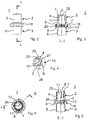
- eine Seitenansicht einer zweckmäßigen Ausgestaltung eines erfindungsgemäßen Leckagenventils;
- Fig. 3
- eine Schnittdarstellung des Leckagenventils gemäß
Fig. 2 entlang der Schnittlinie A-A; - Fig. 4
- eine Detailschnittdarstellung im Bereich Z von
Fig. 3 ; - Fig. 5
- eine Draufsicht auf die Oberseite des Leckagenventils gemäß
Fig. 2 ; - Fig. 6
- eine Schnittdarstellung entlang der gewinkelten Schnittflächen B-B von
Fig. 5 ; sowie - Fig. 7
- eine Darstellung der Funktion bzw. des Zusammenbaus des erfindungsgemäßen Leckagenventils gemäß
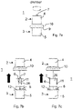
Fig. 2 in verrastetem Zustand (Fig. 7a ), in einer Explosionsdarstellung (Fig. 7b ) sowie ebenfalls in einer Explosionsdarstellung, jedoch um 90° gedreht zuFig. 7b (Fig. 7c ). -
Fig. 1 zeigt ein Beispiel einer Anordnung zur Leckagenbeatmung. Bei der Bezugsziffer 15 handelt es sich um eine am Patienten befindliche Beatmungseinrichtung, wie z.B. eine Beatmungsmaske, die mit einem (nicht dargestellten) Anschlussstutzen versehen ist und mit einem Leckagenventil 1 gemäß der Erfindung verbunden wird. An das Leckagenventil 1 kann sich z.B. ein Konnektor 24 mit einem Anschluss für eine Sonde anschließen. - Des Weiteren ist ein Beatmungsschlauch 13 vorgesehen, welcher bei Bedarf einen Heizdraht beinhalten kann, der dazu vorgesehen ist, das Beatmungsgas innerhalb des Beatmungsschlauchs auf einer bestimmten Temperatur zu halten. Ein Heizdraht muss allerdings nicht unbedingt vorhanden sein. Der Beatmungsschlauch 13 weist an seinem jeweiligen Ende je eine Anschlussmuffe 18, 19 auf. Ferner steht der Beatmungsschlauch 13 über einen weiteren Konnektor 23 mit Anschluss für eine Sonde mit einer Befeuchterkammer 16 eines Luftbefeuchters 14 in Verbindung. In der Befeuchterkammer 16 wird speziell konditioniertes Beatmungsgas bereitgehalten. Die Befeuchterkammer 16 steht über einen Verbindungsschlauch 20 und einen Verbinder 21 mit einem Ventilator 22 in Verbindung. Um einen gewissen Feuchtegehalt des innerhalb der Befeuchterkammer 16 befindlichen Beatmungsgases sicherzustellen, steht diese mit einem Wasserreservoir 17 in Verbindung. Zur Beatmung wird somit das in der Befeuchterkammer 16 bevorratete, konditionierte Beatmungsgas aufgrund des vom Ventilator 22 erzeugten Überdrucks über den Beatmungsschlauch 13 hin zum Patienten befördert. Vom Patienten wird das Beatmungsgas eingeatmet und über die Beatmungsmaske wieder ausgeatmet. Der Patient bekommt hierbei eine Menge an Beatmungsgas zugeführt, die größer ist als die vom Patienten bei der Atmung verbrauchte Menge. Der Rest der vom Beatmungsgas zur Verfügung gestellten Beatmungsgasmenge verlässt den Beatmungskreis über das Leckagenventil 1. Bei der Inspiration durchströmt das Beatmungsgas das Innenlumen des Leckagenventils und wäscht hierbei sogleich auch alle Reste an verbrauchter Luft aus dem Leckagenventil heraus.
- Bei der Handhabung kann es häufig vorkommen, dass sich der Beatmungsschlauch 13 zur am Patienten befindlichen Beatmungseinrichtung, z.B. Beatmungsmaske verdreht, wodurch Torsionskräfte entstehen und auf das Leckagenventil 1 wirken.
-
Fig. 2 zeigt ein Ausführungsbeispiel eines erfindungsgemäßen Leckagenventils. Das Leckagenventil 1 umfasst ein erstes rundes Gehäuseteil 2 sowie zweites rundes Gehäuseteil 3, wobei am ersten Gehäuseteil 2 ein erster Anschlussstutzen 4 und am zweiten Gehäuseteil 3 ein zweiter Anschlussstutzen 5 vorgesehen ist. Mit dem Anschlussstutzen 4 wird das Leckagenventil 1 mit der Beatmungseinrichtung 15, z.B. einer Beatmungsmaske, verbunden. Der zweite Anschlussstutzen 5 dient dazu, das Leckagenventil 1 mit dem Konnektor 24 mit Sondenanschlussmittel oder direkt mit dem Beatmungsschlauch 13 zu verbinden. Etwa im Mittelbereich des Leckagenventils 1 befindet sich ein sich erweiternder Gehäusebereich 10, in dem sich ein umlaufender schmaler Leckagenkanal 9, vgl.Fig. 3 , für den Austritt der Leckagenströmung aus dem Leckagenventil 1 ins Freie befindet. - In
Fig. 3 ist der konstruktive Aufbau des Leckagenventils 1 ersichtlich. Das zweite Gehäuseteil 3 bildet das Innenlumen des Leckagenventils 1, wobei das erste Gehäuseteil 2 an der Außenseite des zweiten Gehäuseteils 3 angeordnet und über eine Schnappverbindung in axialer Richtung verrastet ist. Das erste Gehäuseteil 2 wird hierzu über den zylindrischen Bereich des zweiten Gehäuseteils 3 geschoben. Der zylindrische Bereich weist gekrümmte Wandbereiche 26 auf, zwischen denen Schlitze 11 vorgesehen sind. Durch diese Schlitze 11 werden Rastlaschen 6 mit oberseitigen Nasen 7 gebildet, die mit der oberen Stirnseite des ersten Gehäuseteils 2 verrasten und letzteres somit in einer axialen Halteposition fixieren. Zwischen der Innenwand des ersten Gehäuseteils 2 sowie der Außenseite des zweiten Gehäuseteils 3 ist im Bereich des sich erweiterten Gehäusebereichs 10 ein ringförmiger Leckagenkanal 9 vorgesehen, über den Beatmungsgas ins Freie gelangen kann. - Des Weiteren sind am zweiten Gehäuseteil 3 radial nach außen gerichtete Stege 12 entlang des Umfangs des zweiten Gehäuseteils 3 vorgesehen, welche Durchgangsöffnungen 8 begrenzen. Über die Durchgangsöffnungen 8 kann Beatmungsgas aus dem Innenlumen des Leckagenventils in das Innere des erweiterten Bereichs 10 und von dort in den umlaufenden Leckagenkanal 9 gelangen. Die Durchgangsöffnungen 8 sind großflächig, da sie lediglich von den radial verlaufenden Stegen 12 begrenzt werden.
- Im Bodenbereich der Stege 12 ist eine ringartige Erweiterung 27 vorgesehen, deren außenumfängliche Stirnfläche zusammen mit der Innenwandung des ersten Gehäuseteils 2 im Bereich der Gehäuseerweiterung 10 den Leckagenkanal 9 bildet.
- Das erste Gehäuseteil 2 weist eine vorzugsweise umlaufende Stufenfläche 25 auf, die im verrasteten Zustand der beiden Gehäuseteile 2, 3 oberseitig auf den Stegen 12 aufliegt.
- Die Konzeption ist noch etwas deutlicher in
Fig. 4 ersichtlich. Die ringartige Erweiterung 27 besitzt an deren Unterseite eine umlaufende Ausnehmung 28, die zu einer mechanischen Versteifung des zweiten Gehäuseteils 3 bzw. der ringartigen Erweiterung 27 führt. Durch diese mechanische Stabilität wird verhindert, dass der Leckagenkanal 9 bei mechanischer Beanspruchung sich verändert und damit die Leckagenströmung beeinträchtigt wird. - Die ohne Kraftaufwand durchführbare Verdrehbarkeit der beiden Gehäuseteile 2, 3 im verrasteten Zustand zueinander wird dadurch realisiert, dass zwischen der axial verlaufenden Außenwand des ersten Gehäuseteils 2 im Bereich der Rastlaschen 6 und der Innenwand des ersten Anschlussstutzens 4 ein geringfügiges Spaltspiel vorgesehen ist. Ein entsprechendes Spaltspiel kann auch zwischen der stirnseitigen Nase 7 der Rastlaschen 6 und dem stirnseitigen Ende des ersten Anschlussstutzens 4 vorgesehen sein. Ebenfalls kann ein geringfügiges Spaltspiel auch zwischen der axial verlaufenden Außenwand, der gekrümmten Wandbereiche 26 des ersten Gehäuseteils 2 und der axial verlaufenden Innenwand der ersten Anschlussstutzens 4 vorgesehen sein.
- Das Maß des Spalts (Spaltspiel) für die Drehbarkeit der beiden Gehäuseteile beträgt im Wesentlichen 0,08 mm bis 0,12 mm (d.h. auf den Durchmesser bezogen 0,04 mm bis 0,06 mm pro Seite), vorzugsweise 0,09 mm bis 0,11 mm (d.h. auf den Durchmesser bezogen 0,045 mm bis 0,055 mm pro Seite). Beispielsweise beträgt das Spaltspiel auf den Durchmesser bezogen 0,10 mm, d.h. 0,05 mm pro Seite.
-
Fig. 5 zeigt das Leckagenventil 1 in einer Ansicht von oben. Man erkennt die beiden gegenüberliegenden Rastlaschen 6 mit den oberseitigen stirnseitigen Nasen 7 des ersten Gehäuseteils 2, die das oberseitige Ende des zweiten Gehäuseteils 3 übergreifen. - Wie aus
Fig. 6 deutlich wird, ist der oberseitige Bereich des ersten Gehäuseteils 2, d.h. der gekrümmte Wandbereich 26, bis zur Oberseite der Stege 12 glatt, d.h. ohne Stufe ausgebildet. Gleiches gilt für den außen angeordneten entsprechenden Bereich des ersten Gehäuseteils 2, der den ersten Anschlussstutzen 4 bildet. - Wie aus
Fig. 7a ersichtlich, können die beiden Gehäuseteile 2 und 3 des erfindungsgemäßen Leckagenventils 1 im verrasteten Zustand gegeneinander sehr leicht verdreht werden. Es können sich somit keine Torsionskräfte auf das Gehäuse des Leckagenventils 1 aufbauen, wenn z.B. der Beatmungsschlauch 13 verdreht wird. - Die
Fig. 7b sowie 7c zeigen das Leckagenventil in einer Explosionsdarstellung. Gut erkennbar ist der jeweilige Bereich der entlang des Umfangs vorgesehenen Durchgangsöffnungen 8, durch die hindurch Atemgas aus dem Innenlumen des Leckagenventils 1 in den Ringraum 29 und von dort in den ringförmigen Leckagenkanal 9 (vgl. z.B.Fig. 3 ) gelangen kann. - Die erfindungsgemäße Konstruktion ermöglicht es zudem, die Gehäuseteile 2 sowie 3 einstückig aus Kunststoff in einem Spritzgießverfahren in einfacher Weise herzustellen.
- Es wird ausdrücklich darauf hingewiesen, dass auch Unterkombinationen der beschriebenen Merkmalskomplexe sowie Ausführungsformen ausdrücklich vom Gegenstand der vorliegenden Erfindung als umfasst angesehen werden.
-
- 1
- Leckagenventil
- 2
- erstes Gehäuseteil
- 3
- zweites Gehäuseteil
- 4
- erster Anschlussstutzen
- 5
- zweiter Anschlussstutzen
- 6
- Rastlasche
- 7
- Nase
- 8
- Durchgangsöffnung
- 9
- Leckagenkanal
- 10
- erweiterter Gehäusebereich
- 11
- Schlitz
- 12
- Steg
- 13
- Beatmungsschlauch
- 14
- Befeuchter
- 15
- Beatmungseinrichtung
- 16
- Befeuchterkammer
- 17
- Wasserreservoir
- 18
- Anschlussmuffe
- 19
- Anschlussmuffe
- 20
- Verbindungsschlauch
- 21
- Verbinder
- 22
- Ventilator
- 23
- Konnektor mit Sondenanschlussmittel
- 24
- Konnektor mit Sondenanschlussmittel
- 25
- Stufenfläche
- 26
- gekrümmter Wandbereich
- 27
- ringartige Erweiterung
- 28
- Ausnehmung
- 29
- Ringraum
Claims (13)
- Leckagenventil (1) für den Einsatz in einem Patientenbeatmungssystem mit
einem aus einem ersten (2) und zweiten Gehäuseteil (3) aufgebauten, vorzugsweise aus Kunststoff bestehenden Ventilgehäuse, wobei beide Gehäuseteile (2, 3) einen vorzugsweise im Querschnitt kreisförmigen Fluidkanal bilden, wobei das Ventilgehäuse folgendes umfasst:einen ersten Anschlussstutzen (4) am ersten Gehäuseteil (2),einen zweiten Anschlussstutzen (5) am zweiten Gehäuseteil (3) sowie einen radial nach außen vorspringenden Gehäusebereich (10) zwischen den beiden Anschlussstutzen (4, 5),mindestens eine Durchgangsöffnung (8), die etwa in der Höhe des nach außen vorspringenden Gehäusebereichs (10) angeordnet ist und einen Austritt des Fluides aus dem Fluidkanal in Form einer Leckageströmung ermöglicht bzw. ermöglichen,einen ebenfalls etwa in der Höhe des nach außen vorspringenden Gehäusebereichs (10) angeordneten, zumindest entlang eines Teils, vorzugsweise entlang des gesamten Umfangs des Ventilgehäuses umlaufenden, vorzugsweise durch beide Gehäuseteile (2, 3) gebildeten Leckagekanal (9) für den Austritt der Leckageströmung aus dem Leckageventil (1),einen Verrastmechanismus, mittels dem die beiden Gehäuseteile (2, 3) miteinander verbindbar sind,wobei als Verrastmechanismus mindestens eine, vorzugsweise eine Mehrzahl von entsprechend dem Innenradius des Anschlussstutzens (4 bzw. 5) gekrümmte(n) Rastlasche(n) (6) mit stirnseitiger Nase (7) vorgesehen sind, die im Zustand der Verrastung sich entlang des Anschlussstutzens (4 bzw. 5) innenseitig anliegend erstrecken und mit ihrer Nase (7) an der äußeren Stirnseite des Anschlussstutzens (4 bzw. 5) angreifen und eine axiale Verrastung gewährleisten und zwischen den Rastlaschen (6) entsprechend dem Innenradius des Anschlussstutzens (4 bzw. 5) gekrümmte Wandbereiche (26) vorgesehen sind, die an die Innenfläche des Anschlussstutzens (4 bzw. 5) angrenzen,wobei die beiden Gehäuseteile (2, 3) im verrasteten Zustand zueinander verdrehbar sind,am zweiten Gehäuseteil (3) entlang des Umfangs mehrere radial sich erstreckende Stege (12) vorgesehen sind, zwischen denen die Durchgangsöffnungen (8) vorgesehen sind oder die die Durchgangsöffnungen (8) seitlich begrenzen,die Stege (12) die gekrümmtem Wandbereiche (26) zur Außenseite hin überragen, undzwischen der Innenwand des erweiterten Gehäusebereichs (10) und dem außenseitigen Ende des jeweiligen Stegs (12) ein umlaufender Ringraum (29) besteht. - Leckagenventil nach Anspruch 1, dadurch gekennzeichnet, dass im verrasteten Zustand der beiden Gehäuseteile (2, 3) zwischen der axial verlaufenden Außenwand der Rastlaschen (6) und der axial verlaufenden Innenwand des ersten Anschlussstutzens (4) ein Spaltspiel vorgesehen ist.
- Leckagenventil nach Anspruch 1 oder 2, dadurch gekennzeichnet, dass im verrasteten Zustand der beiden Gehäuseteile (2, 3) zwischen der stirnseitigen Nase (7) der Rastlaschen (6) und dem stirnseitigen Ende des ersten Anschlussstutzens (4) ein Spaltspiel vorgesehen ist,
- Leckagenventil nach den vorhergehenden Ansprüchen, dadurch gekennzeichnet, dass im verrasteten Zustand der beiden Gehäuseteile (2, 3) zwischen der axial verlaufenden Außenwand der gekrümmten Wandbereiche (26) und der axial verlaufenden Innenwand des ersten Anschlussstutzens (4) ein Spaltspiel vorgesehen ist.
- Leckagenventil nach den Ansprüchen 1 bis 4, dadurch gekennzeichnet, dass im verrasteten Zustand der beiden Gehäuseteile (2, 3) der erste Gehäuseteil (2) auf den Stegen (12) aufliegt.
- Leckagenventil nach den Ansprüchen 1 bis 5, dadurch gekennzeichnet, dass das erste Gehäuseteil (2) eine umlaufende Stufenfläche (25) aufweist, die im verrasteten Zustand der beiden Gehäuseteile (2, 3) oberseitig auf den Stegen (12) aufliegt.
- Leckagenventil nach den vorhergehenden Ansprüchen, dadurch gekennzeichnet, dass das erste (2) und/oder zweite Gehäuseteil (3) einteilig ausgebildet sind.
- Leckagenventil nach den vorhergehenden Ansprüchen, dadurch gekennzeichnet, dass das zweite Gehäuseteil (3) im Bereich des erweiterten Gehäusebereichs (10) eine ringartige Erweiterung (27) aufweist.
- Leckagenventil nach Anspruch 8, dadurch gekennzeichnet, dass die ringartige Erweiterung (27) an deren Unterseite mit einer umlaufenden Ausnehmung (28) versehen ist.
- Beatmungsschlauchsystem zur Verwendung bei einer Leckagenbeatmung umfassend einen, vorzugsweise beheizbaren, Beatmungsschlauch (13) sowie ein Leckagenventil (1) gemäß den vorherigen Ansprüchen.
- Beatmungsschlauchsystem nach Anspruch 10, dadurch gekennzeichnet, dass an mindestens einem Ende, vorzugsweise an beiden Enden des Beatmungsschlauchs (13) eine Anschlussmuffe (18, 19) zum Anschluss des Beatmungsschlauchs (13) an das Leckagenventil (1) und/oder ein Funktionsteil vorgesehen ist.
- Beatmungsschlauchsystem nach den Ansprüchen 10 bis 11, dadurch gekennzeichnet, dass sich das Leckagenventil (1) zwischen Anschlussmuffe (18) und einer am Patienten positionierten Beatmungseinrichtung (15) befindet.
- Beatmungsschlauchsystem nach den Ansprüchen 10 bis 12, dadurch gekennzeichnet, dass sich das Leckagenventil (1) zwischen Anschlussmuffe (18) und einem Konnektor (24) mit Sondenanschlussmittel befindet.
Applications Claiming Priority (1)
| Application Number | Priority Date | Filing Date | Title |
|---|---|---|---|
| PCT/EP2019/051781 WO2020151827A1 (de) | 2019-01-24 | 2019-01-24 | Leckagenventil sowie beatmungsschlauchsystem |
Publications (2)
| Publication Number | Publication Date |
|---|---|
| EP3856314A1 EP3856314A1 (de) | 2021-08-04 |
| EP3856314B1 true EP3856314B1 (de) | 2022-12-28 |
Family
ID=65237032
Family Applications (1)
| Application Number | Title | Priority Date | Filing Date |
|---|---|---|---|
| EP19702059.7A Active EP3856314B1 (de) | 2019-01-24 | 2019-01-24 | Leckagenventil sowie beatmungsschlauchsystem |
Country Status (4)
| Country | Link |
|---|---|
| US (1) | US12569641B2 (de) |
| EP (1) | EP3856314B1 (de) |
| JP (1) | JP7257532B2 (de) |
| WO (1) | WO2020151827A1 (de) |
Family Cites Families (11)
| Publication number | Priority date | Publication date | Assignee | Title |
|---|---|---|---|---|
| AUPP855099A0 (en) * | 1999-02-09 | 1999-03-04 | Resmed Limited | Gas delivery connection assembly |
| US5937851A (en) * | 1997-02-27 | 1999-08-17 | Respironics, Inc. | Swivel device utilizing bearing clearance to allow carbon dioxide laden exhaust |
| DE19840760C2 (de) * | 1998-09-07 | 2000-07-20 | Map Medizintechnik Gmbh | Schalldämpfer für Beatmungsvorrichtung |
| DE10014178C2 (de) * | 2000-03-23 | 2003-04-10 | Map Medizin Technologie Gmbh | Vorrichtung zur Ableitung von Atemgas |
| DE10158066A1 (de) * | 2001-11-27 | 2003-06-05 | Weinmann G Geraete Med | Beatmungsmaske |
| DE102007052898B3 (de) * | 2007-11-07 | 2009-04-30 | Dräger Medical AG & Co. KG | Vorrichtung zur Ableitung von Atemgas |
| DE102010045299A1 (de) | 2010-09-14 | 2012-03-15 | Wilamed Gmbh | Leckagenventil |
| EP2844326B1 (de) * | 2012-05-02 | 2020-04-15 | Fisher & Paykel Healthcare Limited | Kommunikationssysteme für einen atemluftbefeuchter |
| WO2013188845A1 (en) * | 2012-06-15 | 2013-12-19 | The Regents Of The University Of California | System and methods for lung isolation and one lung ventilation |
| US10576240B2 (en) * | 2014-10-24 | 2020-03-03 | Koninklijke Philips N.V. | System and method for controlling leak |
| US10315002B2 (en) * | 2015-03-24 | 2019-06-11 | Ventec Life Systems, Inc. | Ventilator with integrated oxygen production |
-
2019
- 2019-01-24 US US17/424,746 patent/US12569641B2/en active Active
- 2019-01-24 WO PCT/EP2019/051781 patent/WO2020151827A1/de not_active Ceased
- 2019-01-24 JP JP2021543319A patent/JP7257532B2/ja active Active
- 2019-01-24 EP EP19702059.7A patent/EP3856314B1/de active Active
Also Published As
| Publication number | Publication date |
|---|---|
| JP2022518799A (ja) | 2022-03-16 |
| US20220105306A1 (en) | 2022-04-07 |
| US12569641B2 (en) | 2026-03-10 |
| JP7257532B2 (ja) | 2023-04-13 |
| EP3856314A1 (de) | 2021-08-04 |
| WO2020151827A1 (de) | 2020-07-30 |
Similar Documents
| Publication | Publication Date | Title |
|---|---|---|
| EP0276024B1 (de) | Konnektions-System für Gasleitungen mit ineinander steckbaren Verbindungselementen für Beatmungs- oder Anästhesie-Geräte | |
| DE19840760C2 (de) | Schalldämpfer für Beatmungsvorrichtung | |
| DE69005086T2 (de) | Sprecheinrichtung zum gebrauch bei sauerstoffversorgung. | |
| EP0054714A2 (de) | Konnektions-System mit ineinandersteckbaren Verbindungselementen für Beatmungs- bzw. Anaestesie-Geräte | |
| EP3624883B1 (de) | Exspirationsventil für eine beatmungsvorrichtung mit geräuschminderndem strömungswiderstand | |
| DE3819237A1 (de) | Endotrachealtubus | |
| DE2947363A1 (de) | Exhalationsventil | |
| EP1620155A1 (de) | Vernebleranschlussvorrichtung für beatmungsgeräte oder dergleichen | |
| DE112012003304T5 (de) | Leitungsverbinder für eine Vorrichtung zur Beatmung von Patienten | |
| DE102012006396A1 (de) | Tracheostomietubus | |
| DE69533070T2 (de) | Beatmungsvorrichtungen mit kontrolliertem zugang | |
| DE102005041717B4 (de) | Atemmaske mit Strömungsleitstrukturen | |
| DE3626790C2 (de) | ||
| DE102017004224A1 (de) | Nasenkanüle für High-Flow-Beatmung | |
| EP2805748B1 (de) | Atemmaske mit Notatemventil | |
| DE19757703C5 (de) | Beatmungsvorrichtung | |
| EP1776153B1 (de) | Vorrichtung zur ableitung von atemgas aus dem innenbereich einer atemmaske, sowie unter einschluss dieser vorrichtung gebildete atemmaskenanordnung an sich | |
| DE10134725A1 (de) | Vorrichtung zur Filterung von Atemluft | |
| DE29721766U1 (de) | Anschlußstück für die Atemgasversorgung eines Patienten | |
| DE4138045A1 (de) | Atemhilfe fuer laryngotomie- bzw. tracheotomypatienten | |
| DE202017102703U1 (de) | Gehäuseaufbau eines Durchflusssensors | |
| EP3144026B1 (de) | Mehrteilige beatmungsmaske, zugehöriges nasenschlusselement und zugehörige kombination eines schlauchanschlusselements und eines kopplungselements | |
| DE102012004359B4 (de) | Kugelgelenk mit zwei Kugelsegmenten | |
| DE202020106578U1 (de) | Vorrichtung zum Koppeln einer Beatmungsmaske oder eines nicht-invasiven Systems mit einem Luft-Sauerstoff-Mischer zur High-Flow-Oxygen-Therapie | |
| DE60108787T2 (de) | Anordnung zur künstlichen beatmung der lungen |
Legal Events
| Date | Code | Title | Description |
|---|---|---|---|
| STAA | Information on the status of an ep patent application or granted ep patent |
Free format text: STATUS: UNKNOWN |
|
| STAA | Information on the status of an ep patent application or granted ep patent |
Free format text: STATUS: THE INTERNATIONAL PUBLICATION HAS BEEN MADE |
|
| PUAI | Public reference made under article 153(3) epc to a published international application that has entered the european phase |
Free format text: ORIGINAL CODE: 0009012 |
|
| STAA | Information on the status of an ep patent application or granted ep patent |
Free format text: STATUS: REQUEST FOR EXAMINATION WAS MADE |
|
| 17P | Request for examination filed |
Effective date: 20210426 |
|
| AK | Designated contracting states |
Kind code of ref document: A1 Designated state(s): AL AT BE BG CH CY CZ DE DK EE ES FI FR GB GR HR HU IE IS IT LI LT LU LV MC MK MT NL NO PL PT RO RS SE SI SK SM TR |
|
| GRAP | Despatch of communication of intention to grant a patent |
Free format text: ORIGINAL CODE: EPIDOSNIGR1 |
|
| STAA | Information on the status of an ep patent application or granted ep patent |
Free format text: STATUS: GRANT OF PATENT IS INTENDED |
|
| GRAJ | Information related to disapproval of communication of intention to grant by the applicant or resumption of examination proceedings by the epo deleted |
Free format text: ORIGINAL CODE: EPIDOSDIGR1 |
|
| STAA | Information on the status of an ep patent application or granted ep patent |
Free format text: STATUS: REQUEST FOR EXAMINATION WAS MADE |
|
| DAV | Request for validation of the european patent (deleted) | ||
| DAX | Request for extension of the european patent (deleted) | ||
| GRAJ | Information related to disapproval of communication of intention to grant by the applicant or resumption of examination proceedings by the epo deleted |
Free format text: ORIGINAL CODE: EPIDOSDIGR1 |
|
| GRAP | Despatch of communication of intention to grant a patent |
Free format text: ORIGINAL CODE: EPIDOSNIGR1 |
|
| GRAP | Despatch of communication of intention to grant a patent |
Free format text: ORIGINAL CODE: EPIDOSNIGR1 |
|
| STAA | Information on the status of an ep patent application or granted ep patent |
Free format text: STATUS: GRANT OF PATENT IS INTENDED |
|
| INTG | Intention to grant announced |
Effective date: 20220420 |
|
| INTC | Intention to grant announced (deleted) | ||
| INTG | Intention to grant announced |
Effective date: 20220512 |
|
| GRAJ | Information related to disapproval of communication of intention to grant by the applicant or resumption of examination proceedings by the epo deleted |
Free format text: ORIGINAL CODE: EPIDOSDIGR1 |
|
| STAA | Information on the status of an ep patent application or granted ep patent |
Free format text: STATUS: REQUEST FOR EXAMINATION WAS MADE |
|
| GRAS | Grant fee paid |
Free format text: ORIGINAL CODE: EPIDOSNIGR3 |
|
| STAA | Information on the status of an ep patent application or granted ep patent |
Free format text: STATUS: GRANT OF PATENT IS INTENDED |
|
| GRAP | Despatch of communication of intention to grant a patent |
Free format text: ORIGINAL CODE: EPIDOSNIGR1 |
|
| INTC | Intention to grant announced (deleted) | ||
| RAP1 | Party data changed (applicant data changed or rights of an application transferred) |
Owner name: LOEWENSTEIN MEDICAL TECHNOLOGY S.A. |
|
| INTG | Intention to grant announced |
Effective date: 20220927 |
|
| GRAA | (expected) grant |
Free format text: ORIGINAL CODE: 0009210 |
|
| STAA | Information on the status of an ep patent application or granted ep patent |
Free format text: STATUS: THE PATENT HAS BEEN GRANTED |
|
| AK | Designated contracting states |
Kind code of ref document: B1 Designated state(s): AL AT BE BG CH CY CZ DE DK EE ES FI FR GB GR HR HU IE IS IT LI LT LU LV MC MK MT NL NO PL PT RO RS SE SI SK SM TR |
|
| REG | Reference to a national code |
Ref country code: GB Ref legal event code: FG4D Free format text: NOT ENGLISH |
|
| REG | Reference to a national code |
Ref country code: CH Ref legal event code: EP |
|
| REG | Reference to a national code |
Ref country code: DE Ref legal event code: R096 Ref document number: 502019006633 Country of ref document: DE |
|
| REG | Reference to a national code |
Ref country code: AT Ref legal event code: REF Ref document number: 1540071 Country of ref document: AT Kind code of ref document: T Effective date: 20230115 |
|
| REG | Reference to a national code |
Ref country code: IE Ref legal event code: FG4D Free format text: LANGUAGE OF EP DOCUMENT: GERMAN |
|
| REG | Reference to a national code |
Ref country code: LT Ref legal event code: MG9D |
|
| PG25 | Lapsed in a contracting state [announced via postgrant information from national office to epo] |
Ref country code: SE Free format text: LAPSE BECAUSE OF FAILURE TO SUBMIT A TRANSLATION OF THE DESCRIPTION OR TO PAY THE FEE WITHIN THE PRESCRIBED TIME-LIMIT Effective date: 20221228 Ref country code: NO Free format text: LAPSE BECAUSE OF FAILURE TO SUBMIT A TRANSLATION OF THE DESCRIPTION OR TO PAY THE FEE WITHIN THE PRESCRIBED TIME-LIMIT Effective date: 20230328 Ref country code: LT Free format text: LAPSE BECAUSE OF FAILURE TO SUBMIT A TRANSLATION OF THE DESCRIPTION OR TO PAY THE FEE WITHIN THE PRESCRIBED TIME-LIMIT Effective date: 20221228 Ref country code: FI Free format text: LAPSE BECAUSE OF FAILURE TO SUBMIT A TRANSLATION OF THE DESCRIPTION OR TO PAY THE FEE WITHIN THE PRESCRIBED TIME-LIMIT Effective date: 20221228 |
|
| REG | Reference to a national code |
Ref country code: NL Ref legal event code: MP Effective date: 20221228 |
|
| PG25 | Lapsed in a contracting state [announced via postgrant information from national office to epo] |
Ref country code: RS Free format text: LAPSE BECAUSE OF FAILURE TO SUBMIT A TRANSLATION OF THE DESCRIPTION OR TO PAY THE FEE WITHIN THE PRESCRIBED TIME-LIMIT Effective date: 20221228 Ref country code: LV Free format text: LAPSE BECAUSE OF FAILURE TO SUBMIT A TRANSLATION OF THE DESCRIPTION OR TO PAY THE FEE WITHIN THE PRESCRIBED TIME-LIMIT Effective date: 20221228 Ref country code: HR Free format text: LAPSE BECAUSE OF FAILURE TO SUBMIT A TRANSLATION OF THE DESCRIPTION OR TO PAY THE FEE WITHIN THE PRESCRIBED TIME-LIMIT Effective date: 20221228 Ref country code: GR Free format text: LAPSE BECAUSE OF FAILURE TO SUBMIT A TRANSLATION OF THE DESCRIPTION OR TO PAY THE FEE WITHIN THE PRESCRIBED TIME-LIMIT Effective date: 20230329 |
|
| P01 | Opt-out of the competence of the unified patent court (upc) registered |
Effective date: 20230523 |
|
| PG25 | Lapsed in a contracting state [announced via postgrant information from national office to epo] |
Ref country code: NL Free format text: LAPSE BECAUSE OF FAILURE TO SUBMIT A TRANSLATION OF THE DESCRIPTION OR TO PAY THE FEE WITHIN THE PRESCRIBED TIME-LIMIT Effective date: 20221228 |
|
| PG25 | Lapsed in a contracting state [announced via postgrant information from national office to epo] |
Ref country code: SM Free format text: LAPSE BECAUSE OF FAILURE TO SUBMIT A TRANSLATION OF THE DESCRIPTION OR TO PAY THE FEE WITHIN THE PRESCRIBED TIME-LIMIT Effective date: 20221228 Ref country code: RO Free format text: LAPSE BECAUSE OF FAILURE TO SUBMIT A TRANSLATION OF THE DESCRIPTION OR TO PAY THE FEE WITHIN THE PRESCRIBED TIME-LIMIT Effective date: 20221228 Ref country code: PT Free format text: LAPSE BECAUSE OF FAILURE TO SUBMIT A TRANSLATION OF THE DESCRIPTION OR TO PAY THE FEE WITHIN THE PRESCRIBED TIME-LIMIT Effective date: 20230428 Ref country code: ES Free format text: LAPSE BECAUSE OF FAILURE TO SUBMIT A TRANSLATION OF THE DESCRIPTION OR TO PAY THE FEE WITHIN THE PRESCRIBED TIME-LIMIT Effective date: 20221228 Ref country code: EE Free format text: LAPSE BECAUSE OF FAILURE TO SUBMIT A TRANSLATION OF THE DESCRIPTION OR TO PAY THE FEE WITHIN THE PRESCRIBED TIME-LIMIT Effective date: 20221228 Ref country code: CZ Free format text: LAPSE BECAUSE OF FAILURE TO SUBMIT A TRANSLATION OF THE DESCRIPTION OR TO PAY THE FEE WITHIN THE PRESCRIBED TIME-LIMIT Effective date: 20221228 |
|
| PG25 | Lapsed in a contracting state [announced via postgrant information from national office to epo] |
Ref country code: SK Free format text: LAPSE BECAUSE OF FAILURE TO SUBMIT A TRANSLATION OF THE DESCRIPTION OR TO PAY THE FEE WITHIN THE PRESCRIBED TIME-LIMIT Effective date: 20221228 Ref country code: PL Free format text: LAPSE BECAUSE OF FAILURE TO SUBMIT A TRANSLATION OF THE DESCRIPTION OR TO PAY THE FEE WITHIN THE PRESCRIBED TIME-LIMIT Effective date: 20221228 Ref country code: IS Free format text: LAPSE BECAUSE OF FAILURE TO SUBMIT A TRANSLATION OF THE DESCRIPTION OR TO PAY THE FEE WITHIN THE PRESCRIBED TIME-LIMIT Effective date: 20230428 Ref country code: AL Free format text: LAPSE BECAUSE OF FAILURE TO SUBMIT A TRANSLATION OF THE DESCRIPTION OR TO PAY THE FEE WITHIN THE PRESCRIBED TIME-LIMIT Effective date: 20221228 |
|
| PG25 | Lapsed in a contracting state [announced via postgrant information from national office to epo] |
Ref country code: MC Free format text: LAPSE BECAUSE OF FAILURE TO SUBMIT A TRANSLATION OF THE DESCRIPTION OR TO PAY THE FEE WITHIN THE PRESCRIBED TIME-LIMIT Effective date: 20221228 Ref country code: LU Free format text: LAPSE BECAUSE OF NON-PAYMENT OF DUE FEES Effective date: 20230124 |
|
| REG | Reference to a national code |
Ref country code: DE Ref legal event code: R097 Ref document number: 502019006633 Country of ref document: DE |
|
| REG | Reference to a national code |
Ref country code: BE Ref legal event code: MM Effective date: 20230131 |
|
| PG25 | Lapsed in a contracting state [announced via postgrant information from national office to epo] |
Ref country code: DK Free format text: LAPSE BECAUSE OF FAILURE TO SUBMIT A TRANSLATION OF THE DESCRIPTION OR TO PAY THE FEE WITHIN THE PRESCRIBED TIME-LIMIT Effective date: 20221228 |
|
| PLBE | No opposition filed within time limit |
Free format text: ORIGINAL CODE: 0009261 |
|
| STAA | Information on the status of an ep patent application or granted ep patent |
Free format text: STATUS: NO OPPOSITION FILED WITHIN TIME LIMIT |
|
| PG25 | Lapsed in a contracting state [announced via postgrant information from national office to epo] |
Ref country code: BE Free format text: LAPSE BECAUSE OF NON-PAYMENT OF DUE FEES Effective date: 20230131 |
|
| 26N | No opposition filed |
Effective date: 20230929 |
|
| PG25 | Lapsed in a contracting state [announced via postgrant information from national office to epo] |
Ref country code: SI Free format text: LAPSE BECAUSE OF FAILURE TO SUBMIT A TRANSLATION OF THE DESCRIPTION OR TO PAY THE FEE WITHIN THE PRESCRIBED TIME-LIMIT Effective date: 20221228 Ref country code: IE Free format text: LAPSE BECAUSE OF NON-PAYMENT OF DUE FEES Effective date: 20230124 |
|
| PG25 | Lapsed in a contracting state [announced via postgrant information from national office to epo] |
Ref country code: IT Free format text: LAPSE BECAUSE OF FAILURE TO SUBMIT A TRANSLATION OF THE DESCRIPTION OR TO PAY THE FEE WITHIN THE PRESCRIBED TIME-LIMIT Effective date: 20221228 |
|
| PG25 | Lapsed in a contracting state [announced via postgrant information from national office to epo] |
Ref country code: BG Free format text: LAPSE BECAUSE OF FAILURE TO SUBMIT A TRANSLATION OF THE DESCRIPTION OR TO PAY THE FEE WITHIN THE PRESCRIBED TIME-LIMIT Effective date: 20221228 |
|
| PG25 | Lapsed in a contracting state [announced via postgrant information from national office to epo] |
Ref country code: BG Free format text: LAPSE BECAUSE OF FAILURE TO SUBMIT A TRANSLATION OF THE DESCRIPTION OR TO PAY THE FEE WITHIN THE PRESCRIBED TIME-LIMIT Effective date: 20221228 |
|
| REG | Reference to a national code |
Ref country code: AT Ref legal event code: MM01 Ref document number: 1540071 Country of ref document: AT Kind code of ref document: T Effective date: 20240124 |
|
| PG25 | Lapsed in a contracting state [announced via postgrant information from national office to epo] |
Ref country code: AT Free format text: LAPSE BECAUSE OF NON-PAYMENT OF DUE FEES Effective date: 20240124 |
|
| PG25 | Lapsed in a contracting state [announced via postgrant information from national office to epo] |
Ref country code: CY Free format text: LAPSE BECAUSE OF FAILURE TO SUBMIT A TRANSLATION OF THE DESCRIPTION OR TO PAY THE FEE WITHIN THE PRESCRIBED TIME-LIMIT; INVALID AB INITIO Effective date: 20190124 |
|
| PG25 | Lapsed in a contracting state [announced via postgrant information from national office to epo] |
Ref country code: HU Free format text: LAPSE BECAUSE OF FAILURE TO SUBMIT A TRANSLATION OF THE DESCRIPTION OR TO PAY THE FEE WITHIN THE PRESCRIBED TIME-LIMIT; INVALID AB INITIO Effective date: 20190124 |
|
| PG25 | Lapsed in a contracting state [announced via postgrant information from national office to epo] |
Ref country code: TR Free format text: LAPSE BECAUSE OF FAILURE TO SUBMIT A TRANSLATION OF THE DESCRIPTION OR TO PAY THE FEE WITHIN THE PRESCRIBED TIME-LIMIT Effective date: 20221228 |
|
| REG | Reference to a national code |
Ref country code: CH Ref legal event code: U11 Free format text: ST27 STATUS EVENT CODE: U-0-0-U10-U11 (AS PROVIDED BY THE NATIONAL OFFICE) Effective date: 20260201 |
|
| PGFP | Annual fee paid to national office [announced via postgrant information from national office to epo] |
Ref country code: GB Payment date: 20260122 Year of fee payment: 8 |
|
| PGFP | Annual fee paid to national office [announced via postgrant information from national office to epo] |
Ref country code: DE Payment date: 20260120 Year of fee payment: 8 |
|
| PGFP | Annual fee paid to national office [announced via postgrant information from national office to epo] |
Ref country code: AT Payment date: 20260410 Year of fee payment: 5 |
|
| PGFP | Annual fee paid to national office [announced via postgrant information from national office to epo] |
Ref country code: FR Payment date: 20260121 Year of fee payment: 8 |
|
| PGFP | Annual fee paid to national office [announced via postgrant information from national office to epo] |
Ref country code: CH Payment date: 20260201 Year of fee payment: 8 |