EP2428308A2 - Schweißsysteme und -verfahren - Google Patents
Schweißsysteme und -verfahren Download PDFInfo
- Publication number
- EP2428308A2 EP2428308A2 EP11180644A EP11180644A EP2428308A2 EP 2428308 A2 EP2428308 A2 EP 2428308A2 EP 11180644 A EP11180644 A EP 11180644A EP 11180644 A EP11180644 A EP 11180644A EP 2428308 A2 EP2428308 A2 EP 2428308A2
- Authority
- EP
- European Patent Office
- Prior art keywords
- joint
- welding
- weld
- face
- sensor
- Prior art date
- Legal status (The legal status is an assumption and is not a legal conclusion. Google has not performed a legal analysis and makes no representation as to the accuracy of the status listed.)
- Withdrawn
Links
Images



Classifications
-
- B—PERFORMING OPERATIONS; TRANSPORTING
- B23—MACHINE TOOLS; METAL-WORKING NOT OTHERWISE PROVIDED FOR
- B23K—SOLDERING OR UNSOLDERING; WELDING; CLADDING OR PLATING BY SOLDERING OR WELDING; CUTTING BY APPLYING HEAT LOCALLY, e.g. FLAME CUTTING; WORKING BY LASER BEAM
- B23K26/00—Working by laser beam, e.g. welding, cutting or boring
- B23K26/20—Bonding
- B23K26/21—Bonding by welding
- B23K26/24—Seam welding
-
- B—PERFORMING OPERATIONS; TRANSPORTING
- B23—MACHINE TOOLS; METAL-WORKING NOT OTHERWISE PROVIDED FOR
- B23K—SOLDERING OR UNSOLDERING; WELDING; CLADDING OR PLATING BY SOLDERING OR WELDING; CUTTING BY APPLYING HEAT LOCALLY, e.g. FLAME CUTTING; WORKING BY LASER BEAM
- B23K15/00—Electron-beam welding or cutting
- B23K15/0013—Positioning or observing workpieces, e.g. with respect to the impact; Aligning, aiming or focusing electron beams
-
- B—PERFORMING OPERATIONS; TRANSPORTING
- B23—MACHINE TOOLS; METAL-WORKING NOT OTHERWISE PROVIDED FOR
- B23K—SOLDERING OR UNSOLDERING; WELDING; CLADDING OR PLATING BY SOLDERING OR WELDING; CUTTING BY APPLYING HEAT LOCALLY, e.g. FLAME CUTTING; WORKING BY LASER BEAM
- B23K15/00—Electron-beam welding or cutting
- B23K15/002—Devices involving relative movement between electron beam and workpiece
-
- B—PERFORMING OPERATIONS; TRANSPORTING
- B23—MACHINE TOOLS; METAL-WORKING NOT OTHERWISE PROVIDED FOR
- B23K—SOLDERING OR UNSOLDERING; WELDING; CLADDING OR PLATING BY SOLDERING OR WELDING; CUTTING BY APPLYING HEAT LOCALLY, e.g. FLAME CUTTING; WORKING BY LASER BEAM
- B23K15/00—Electron-beam welding or cutting
- B23K15/0046—Welding
- B23K15/0053—Seam welding
- B23K15/006—Seam welding of rectilinear seams
-
- B—PERFORMING OPERATIONS; TRANSPORTING
- B23—MACHINE TOOLS; METAL-WORKING NOT OTHERWISE PROVIDED FOR
- B23K—SOLDERING OR UNSOLDERING; WELDING; CLADDING OR PLATING BY SOLDERING OR WELDING; CUTTING BY APPLYING HEAT LOCALLY, e.g. FLAME CUTTING; WORKING BY LASER BEAM
- B23K26/00—Working by laser beam, e.g. welding, cutting or boring
- B23K26/02—Positioning or observing the workpiece, e.g. with respect to the point of impact; Aligning, aiming or focusing the laser beam
- B23K26/03—Observing, e.g. monitoring, the workpiece
- B23K26/0342—Observing magnetic fields related to the workpiece
-
- B—PERFORMING OPERATIONS; TRANSPORTING
- B23—MACHINE TOOLS; METAL-WORKING NOT OTHERWISE PROVIDED FOR
- B23K—SOLDERING OR UNSOLDERING; WELDING; CLADDING OR PLATING BY SOLDERING OR WELDING; CUTTING BY APPLYING HEAT LOCALLY, e.g. FLAME CUTTING; WORKING BY LASER BEAM
- B23K26/00—Working by laser beam, e.g. welding, cutting or boring
- B23K26/02—Positioning or observing the workpiece, e.g. with respect to the point of impact; Aligning, aiming or focusing the laser beam
- B23K26/04—Automatically aligning, aiming or focusing the laser beam, e.g. using the back-scattered light
- B23K26/044—Seam tracking
-
- B—PERFORMING OPERATIONS; TRANSPORTING
- B23—MACHINE TOOLS; METAL-WORKING NOT OTHERWISE PROVIDED FOR
- B23K—SOLDERING OR UNSOLDERING; WELDING; CLADDING OR PLATING BY SOLDERING OR WELDING; CUTTING BY APPLYING HEAT LOCALLY, e.g. FLAME CUTTING; WORKING BY LASER BEAM
- B23K26/00—Working by laser beam, e.g. welding, cutting or boring
- B23K26/08—Devices involving relative movement between laser beam and workpiece
- B23K26/0869—Devices involving movement of the laser head in at least one axial direction
Definitions
- the present invention generally relates to welding systems and methods, and more particularly relates to welding systems and methods for tracking a joint between two or more work pieces to be welded.
- High energy beam welding such as laser beam or electron beam welding
- laser beam or electron beam welding is used to join one work piece to another work piece by directing a highly focused beam of energy into a joint between the work pieces to heat and fuse them together.
- One common type of welding joint is a butt joint in which an edge portion of one work piece is placed in abutting fashion generally against an edge portion of another work piece before welding the edges together.
- Exact positioning of the welding beam relative to the joint is essential for a high-quality weld, particularly as the welding beam travels along the joint during the welding process.
- the welding beam may be laterally offset with the joint, at an incorrect angle relative to the joint, or at an incorrect beam width. Imprecise positioning of the welding beam may result in an unsatisfactory weld, and the quality of the weld may impact many aspects of the completed part, including the microstructure, microhardness, tensile properties, formability, fatigue strength, fracture toughness, and the overall value of the joining process.
- a non-contacting sensor such as an optical imaging sensor, may be able to repeatedly scan the joint to be welded to provide a map of joint geometry.
- optical imaging may be sensitive to the level of ambient light and smoke emitted by the welding process, and subjective evaluations of the visual image to be tracked may also be an issue.
- An additional problem with many tracking devices includes the difficulty of positioning the sensors at inaccessible portions of the joint.
- a welding system for welding a first work piece to a second work piece at a joint having a weld face and a root face.
- the welding system includes a weld face sensor configured to determine first joint characteristics at the weld face; a root face sensor configured to determine second joint characteristics at the root face; a controller coupled to the weld face sensor and the root face sensor and configured to generate positioning signals based on the first joint characteristics and the second joint characteristics; and a welding gun coupled to the controller and positioned proximate to the weld face, the welding gun configured to generate a welding beam for welding the joint based on the positioning signals from the controller.
- a system for tracking a joint extending from first faces of work pieces to second faces of the work pieces.
- the system includes first sensor configured to generate first joint characteristics of the joint at the first faces; a second sensor configured to generate second joint characteristics of the joint at the second faces; and an encoder coupled to the first sensor and the second sensor and configured to determine a joint position based on the first joint characteristics and the second joint characteristics.
- FIG. 1 is a top schematic view of welding system in accordance with an exemplary embodiment
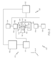
- FIG. 2 is a side schematic view of the welding system of FIG. 1 in accordance with an exemplary embodiment
- FIG. 3 is a flow chart depicting a welding method in accordance with an exemplary embodiment
- FIG. 4 is an exemplary weld associated with the welding system of FIGS. 1 and 2 in accordance with an exemplary embodiment
- FIG. 5 is an exemplary weld associated with the welding system of FIGS. 1 and 2 in accordance with another exemplary embodiment
- FIG. 6 is an exemplary weld associated with the welding system of FIGS. 1 and 2 in accordance with another exemplary embodiment.
- FIG. 7 is an exemplary weld associated with the welding system of FIGS. 1 and 2 in accordance with another exemplary embodiment.
- exemplary embodiments discussed herein are directed to welding systems and methods for welding a joint between first and second work pieces.
- the welding system includes a sensor system and a beam system.
- a weld face sensor of the sensor system tracks the joint at the weld face and a root sensor tracks the joint at the root face such that the sensor system provides more accurate indications of joint geometry, and thus, an improved weld during the subsequent welding process.
- FIG. 1 is a top schematic view of welding system 100 in accordance with an exemplary embodiment for welding a first work piece 110 to a second work piece 120.
- the welding system 100 includes a sensor system 150 that tracks the geometry of a joint 130 between the first and second work pieces 110, 120.
- the sensor system 150 tracks the joint 130 generally in the y-direction, as indicated by arrow 134, although the sensor system 150 may also note variations of the joint 130 in the x- and z-directions.
- a beam system 170 follows the sensor system 150 and generates a high energy beam absorbed by portions of the work pieces 110, 120 at the joint 130 that melt to form a weld 132.
- the sensor system 150 and beam system 170 are discussed in greater detail below.
- FIG. 2 is a side schematic view that illustrates the welding system 100 of FIG. 1 in greater detail.
- the welding system 100 welds the joint 130 between the first work piece 110 and the second work piece 120.
- the joint 130 is defined by respective edges 112, 122 of the first and second work pieces 110, 120 and extends to a depth 134 in a z-direction and along a path further defined in x- and y-directions.
- Each of the work pieces 110, 120 have upper surfaces 114, 124 and lower surfaces 116, 126 relative to the view of FIG. 2 .
- the areas of the joint 130 proximate to the upper surfaces 114, 124 may be referred to as a weld face 136, and the areas of the joint 130 proximate to the lower surfaces 116, 126 may be referred to as a root face 138.
- the joint 130 at the weld face 136 is defined by a weld face thickness 146
- the joint 130 at the root face 138 is defined by a root face thickness 148.
- the relative position of the first and second work pieces 110, 120 in FIGS. 1 and 2 is generally referred to as a butt weld in that the abutting edges 112, 122 of the work pieces 110, 120 are to be welded together.
- the weld face thickness 146 is approximately equal to the root face thickness 148 and the edges 112, 122 are generally perpendicular to the upper surfaces 114, 124 of the work pieces 110, 120 to form a constant right angle butt weld.
- the welding system 100 may also be utilized on tapered joints in which the weld face thickness 146 is different than the root face thickness 148, joints in which both edges 112, 122 are angled, and/or other geometries, including fully penetrated groove welds, fillet welds, angle welds, and other type of welds.
- the welding system 100 generally includes the sensor system 150 and the beam system 170.
- the sensor system 150 includes a weld face sensor 152, a weld face driver 154, a root face sensor 156, a root face driver 158, and an encoder 160.
- the beam system 170 includes a controller 172, a welding support 174, and a welding gun 176.
- the welding gun 176 is positioned proximate to the joint 130 by the welding support 174.
- the welding support 174 is additionally capable of translating the welding gun 176 along the joint 130, generally in one or more of the x-, y-, and z-directions.
- the welding support 174 may also orient the welding gun 176 at any angle. Any suitable rail, track, robot, motors, or the like may form part of the welding support 174 to manipulate the welding gun 176.
- the welding gun 176 is generally operable to weld the opposing edges 112, 122 by directing a focused energy beam onto the work pieces 110, 120 and heating the opposing edges 112, 122 such that the edges 112, 122 at the work pieces 110, 120 melt together and bridge the gap of the joint 130.
- the welding gun 176 may produce, for example, a laser beam or an electron beam at a power sufficient to weld the work pieces 110, 120.
- the source of high energy density radiation is a laser, it may be a CO 2 laser, a CO laser, an excimer laser, another type of gas laser, or a solid state laser such as a YAG laser that operates in continuous wave mode, pulse mode, modulated mode, rippled mode, or another type of operating mode.
- a focusing mirror (not shown) or other optical elements may be provided to ensure desired beam positioning. Other types of thermal energy beams may also be provided.
- the welding gun 176 it is generally desirable for the welding gun 176 to produce a beam aligned with a central axis of the joint 130 and with a width that encompasses the greatest thickness of the joint 130, i.e., the greater of the weld face thickness 146 and the root face thickness 148.
- the sensor system 150 functions to provide information used to optimally position the welding gun 176 in this manner.
- the sensor system 150 includes the weld face sensor 152 and the root face sensor 156. Relative to the first and second work pieces 110, 120, the weld face sensor 152 is positioned proximate to the weld face 136 to measure joint characteristic, including the position of the joint 130 at the weld face 136 in the xy-plane as well as the thickness 146.
- the weld face driver 154 generally includes a support (not shown) and a motor (not shown) configured to move the weld face sensor 152 along the weld face 136. As such, the weld face driver 154 may position the weld face sensor 152 in the x-, y-, and z-directions relative to the work pieces 110, 120.
- the root face sensor 156 is positioned proximate to the root face 138 to measure joint characteristic, including the position of the joint 130 at the root face 138 in the xy-plane as well as the thickness 148.
- the root face driver 158 generally includes a support (not shown) and a motor (not shown) configured to move the root face sensor 156 along the root face 138 in any of the x-, y-, and z-directions.
- the sensors 152, 156 may be eddy current sensors that provide the sensitivity and resolution required for the continuous and precise tracking of the joint 130 with any geometry.
- the sensors 152, 156 may respectively include drive coils carrying currents that generate a primary magnetic field, which in turn, induces eddy currents in the work pieces 110, 120 to generate a secondary magnetic field. Discontinuities in the work pieces 110, 120, such as the joint 130, alter the eddy current flow and the orientation of the secondary magnetic field, which are sensed by sensing coils in the sensors 152, 156 to generate deviation signals. Accordingly, the sensors 152, 156 are omni-directional with respect to the joint 130.
- the encoder 160 coupled to the sensors 152, 156 uses these deviation signals and the position of the sensors 152, 156 to determine the geometry of the joint 130. As the sensors 152, 156 scan the work pieces 110, 120, the weld face sensor 152 tracks the position of the joint 130 at the weld face 136 and the weld face thickness 146, and the root face sensor 156 tracks the position of the joint 130 at the root face 138 and the root face thickness 148.
- the encoder 160 provides information defining the position of the joint 130 at the weld face 136, the position of the joint 130 at the root face 138, the weld face thickness 146, and the root face thickness 148 to the welding controller 172. Other aspects of joint geometry information may also be provided.
- the controller 172 plots a path and operating parameters of the welding gun 176.
- the path may include the necessary movements of the welding gun 176 along the joint 130 in one or more of the x-, y-, and z-directions.
- the operating parameters may include the angle of the welding gun 176, beam characteristics, and timing information.
- the controller 172 evaluates joint geometry, determines the appropriate sequence of welding instructions (or positioning signals), and provides such instructions to the welding support 174 for execution at the welding gun 176. As described above, the welding gun 176 welds the joint 130 according to these instructions to provide a high quality weld at the joint 130 to join the first and second work pieces 110, 120.
- the sensor system 150 maps the entire joint 130 prior to execution by the beam system 170, while in other embodiments, the beam system 170 follows the sensor system 150 to track and weld the joint 130 in real time.
- the embodiments discussed above include a movable welding support 174 for adjusting the position of the welding gun 176 and drivers 154, 158 for adjusting the positions of the sensors 152, 156; however, in other embodiments, the welding gun 176 and sensors 152, 156 may be stationary, and the controller 172 may be coupled to a motor and support system that move the work pieces 110, 120 relative to the sensors 152, 156 and welding gun 176.
- the root face 138 is inaccessible to visual inspection due to the geometry of the second work piece 120.
- Inaccessible root faces are common occurrences in welding operations. Many conventional welding systems do not consider the geometry of the root face at all, but even those that do are not able accurately to track the joint at the root face in such situations.
- the eddy current sensor 156 of the welding system 100 at the root face 138 is able to evaluate the root face geometry regardless of visual accessibility to result in a high quality weld in any situation.
- Other sensors may include laser, ultrasound, air coupled ultrasound, and electromagnetic acoustic transducers.
- FIG. 3 is a flow chart depicting a welding method 300 in accordance with an exemplary embodiment.
- the method 300 may be used with the system 100 discussed above. As such, additional reference is made to FIGS. 1 and 2 .
- the weld face sensor 152 scans the joint 130 at the weld face 136 to determine the position of the joint 130 at the weld face 136 as well as the weld face thickness 146.
- the controller 172 determines if the weld face thickness 146 exceeds a predetermined value. If the weld face thickness 146 is greater than a predetermined value, the method 300 is stopped and the work pieces 110, 120 are rejected, the joint 130 is prepared with additional material such that the joint 130 is suitable for welding, and/or the beam width is increased to accommodate the weld face thickness 146.
- the method 300 proceeds to step 315 in which the root face sensor 156 scans the joint 130 at the root face 138 to determine the position of the joint 130 at the root face 138 as well as the root face thickness 148.
- the controller 172 determines if the root face thickness 148 exceeds a predetermined value. If the root face thickness 148 is greater than a predetermined value, the method 300 is stopped and the work pieces 110, 120 are rejected and/or the joint 130 is prepared with additional material such that the joint 130 is suitable for welding.
- the method 300 proceeds to step 325 in which the controller 172 compares the weld face thickness 146 to the root face thickness 148 to determine the taper, if applicable, of the joint 130. If the weld face thickness 146 and the root face thickness 148 are not equal, the joint 130 is tapered. In a step 330, the controller 172 compares the xy-coordinates of the joint 130 at the weld face 136 and the root face 138 to determine if the joint 130 is angled. For example, for any given z-axis, the joint 130 may have matching xy-coordinates on the weld face 136 and the root face 138, which indicates that the joint 130 is not angled.
- the joint 130 is angled.
- the welding gun 176 is properly aligned and positioned according to the taper characteristics and the angle of the joint 130, and in step 340, the welding gun 176 welds and tracks the joint with consideration for the position, angle, and taper of the joint 130 to result in a suitable weld between the first and second work pieces 110, 120.
- the controller 172 determines when the weld is complete. If the weld is complete, the method 300 stops. If the weld is not complete, the method 300 returns to step 335 in one exemplary embodiment. In other embodiments, the method 300 may return to step 305 depending on whether the method 300 determines and tracks the entire joint 130 or the method 300 determines and tracks the joint 130 in iterations or in real-time.
- FIGS. 4-7 are side cross-sectional views of other types of welds according to the system 100 and method 300 described above.
- FIG. 4 illustrates an exemplary welding beam 400 produced by a welding gun properly aligned to weld the joint 430 between first and second work pieces 410, 420.
- the joint 430 in FIG. 4 is a tapered joint 430 in that the thickness at the root face 438 is greater than the thickness at the weld face 436.
- the beam 400 has sufficient width to join the edges 412, 422 across the joint 430 (e.g., a beam width greater than or equal to eh thickness at the root face 438).
- FIG. 5 illustrates an exemplary welding beam 500 produced by a welding gun properly aligned to weld the joint 530 between first and second work pieces 510, 520.
- the joint 530 in FIG. 5 may be, for example, a fully penetrated groove weld joint 500.
- the beam 500 has sufficient width to join the edges 512, 522 across the joint 530.
- FIG. 6 illustrates an exemplary welding beam 600 produced by a welding gun properly aligned to weld the joint 630 between first and second work pieces 610, 620.
- FIG. 6 may be, for example, a fillet weld joint 630, and the beam 600 has sufficient width and angle to join the edges 612, 622 across the joint 630.
- FIG. 7 illustrates an exemplary welding beam 700 produced by a welding gun properly aligned to weld the joint 730 between first, second, and third work pieces 710, 720, 725.
- the joint 730 in FIG. 7 may be, for example, an angled joint such as that required to couple turbine blades to compressor disks.
- the beam 700 has sufficient width, angle, and depth to join the three work pieces 710, 720, 725 at the joint 730.
- exemplary embodiments may accommodate situations such as tolerance differences, excessive gap, edge break, and other anomalies such as misalignments that would otherwise result in beam deflection, cutting, or missed joint welds.
- Exemplary embodiments may also produce reliable, consistent, and reproducible welds, regardless of the machine or operator skill.
- the metal to metal joining requirements of the aerospace industry are particularly well suited to these systems and methods.
- Exemplary embodiments may be advantageously employed in a number of different types of material processing systems.
Landscapes
- Engineering & Computer Science (AREA)
- Physics & Mathematics (AREA)
- Optics & Photonics (AREA)
- Mechanical Engineering (AREA)
- Plasma & Fusion (AREA)
- Welding Or Cutting Using Electron Beams (AREA)
- Laser Beam Processing (AREA)
- Butt Welding And Welding Of Specific Article (AREA)
Applications Claiming Priority (1)
| Application Number | Priority Date | Filing Date | Title |
|---|---|---|---|
| US12/879,783 US8716627B2 (en) | 2010-09-10 | 2010-09-10 | Welding systems and methods |
Publications (2)
| Publication Number | Publication Date |
|---|---|
| EP2428308A2 true EP2428308A2 (de) | 2012-03-14 |
| EP2428308A3 EP2428308A3 (de) | 2013-02-27 |
Family
ID=45420276
Family Applications (1)
| Application Number | Title | Priority Date | Filing Date |
|---|---|---|---|
| EP11180644A Withdrawn EP2428308A3 (de) | 2010-09-10 | 2011-09-08 | Schweißsysteme und -verfahren |
Country Status (2)
| Country | Link |
|---|---|
| US (1) | US8716627B2 (de) |
| EP (1) | EP2428308A3 (de) |
Cited By (1)
| Publication number | Priority date | Publication date | Assignee | Title |
|---|---|---|---|---|
| EP2687820A3 (de) * | 2012-07-19 | 2016-03-30 | Dr. Johannes Heidenhain GmbH | Maßverkörperung, Verfahren zur Herstellung und Verwendung einer Maßverkörperung |
Families Citing this family (9)
| Publication number | Priority date | Publication date | Assignee | Title |
|---|---|---|---|---|
| CN105705289B (zh) * | 2013-11-15 | 2018-06-22 | 松下知识产权经营株式会社 | 激光焊接条件确定方法以及激光焊接装置 |
| WO2016051807A1 (ja) * | 2014-10-02 | 2016-04-07 | 日本特殊陶業株式会社 | 判定方法、レーザ装置、及びセンサの製造方法 |
| US11179793B2 (en) * | 2017-09-12 | 2021-11-23 | Autodesk, Inc. | Automated edge welding based on edge recognition using separate positioning and welding robots |
| US11078762B2 (en) | 2019-03-05 | 2021-08-03 | Swm International, Llc | Downhole perforating gun tube and components |
| US10689955B1 (en) | 2019-03-05 | 2020-06-23 | SWM International Inc. | Intelligent downhole perforating gun tube and components |
| US12291945B1 (en) | 2019-03-05 | 2025-05-06 | Swm International, Llc | Downhole perforating gun system |
| US11268376B1 (en) | 2019-03-27 | 2022-03-08 | Acuity Technical Designs, LLC | Downhole safety switch and communication protocol |
| AT522660A1 (de) * | 2019-06-04 | 2020-12-15 | Smf Friedlbinder Gmbh | Verfahren und Vorrichtung zur automatischen Steuerung eines Metall-Schweißprozesses |
| US11619119B1 (en) | 2020-04-10 | 2023-04-04 | Integrated Solutions, Inc. | Downhole gun tube extension |
Family Cites Families (16)
| Publication number | Priority date | Publication date | Assignee | Title |
|---|---|---|---|---|
| DE2634341A1 (de) | 1976-07-30 | 1978-02-02 | Steigerwald Strahltech | Verfahren und einrichtung zum ausrichten eines ladungstraegerstrahles eines technischen ladungstraegerstrahlgeraetes |
| JPS5317543A (en) | 1976-07-30 | 1978-02-17 | Steigerwald Strahltech | Method of controlling procedure parameters in energyy beam welding and apparatus therefor |
| US4495587A (en) | 1981-12-08 | 1985-01-22 | Bethlehem Steel Corporation | Automatic nondestructive roll defect inspection system |
| US4830261A (en) | 1987-10-29 | 1989-05-16 | Laser Limited, Inc. | Eddy current tool positioning system |
| US4988201A (en) * | 1988-09-14 | 1991-01-29 | Nkk Corporation | Apparatus for detecting a shape of a groove |
| US5045668A (en) | 1990-04-12 | 1991-09-03 | Armco Inc. | Apparatus and method for automatically aligning a welding device for butt welding workpieces |
| US5463201A (en) * | 1993-02-04 | 1995-10-31 | Generla Electric Company | Seam-tracking apparatus for a welding system employing an array of eddy current elements |
| DK0770445T3 (da) * | 1995-10-06 | 2002-02-18 | Elpatronic Ag | Fremgangsmåde til at kontrollere og postionere en stråle til bearbejdning af emner |
| US5925268A (en) | 1996-06-06 | 1999-07-20 | Engauge Inc. | Laser welding apparatus employing a tilting mechanism and seam follower |
| US6437281B1 (en) * | 1999-08-05 | 2002-08-20 | Yuming Zhang | Apparatus, system, and related method for sensing a characteristic of a workpiece in an automated process |
| CA2465231C (en) | 2001-11-15 | 2011-08-09 | Elpatronic Ag | Method and device for evaluation of jointing regions on workpieces |
| DE10234242B4 (de) | 2002-07-09 | 2005-10-27 | Airbus Deutschland Gmbh | Anordnung und Verfahren zur Regelung der Nahtlage eines laserstrahlgefügten Profils |
| US7094989B2 (en) * | 2004-04-12 | 2006-08-22 | Battelle Energy Alliance, Llc | Welding apparatus and methods for using ultrasonic sensing |
| US7015690B2 (en) | 2004-05-27 | 2006-03-21 | General Electric Company | Omnidirectional eddy current probe and inspection system |
| US7289913B2 (en) | 2004-10-08 | 2007-10-30 | Jentek Sensors, Inc. | Local feature characterization using quasistatic electromagnetic sensors |
| DE102006045523A1 (de) | 2006-09-27 | 2008-04-03 | Airbus Deutschland Gmbh | Reibrührschweißkopf sowie Verfahren zur Steuerung eines Reibrührschweißkopfes |
-
2010
- 2010-09-10 US US12/879,783 patent/US8716627B2/en not_active Expired - Fee Related
-
2011
- 2011-09-08 EP EP11180644A patent/EP2428308A3/de not_active Withdrawn
Non-Patent Citations (1)
| Title |
|---|
| None |
Cited By (1)
| Publication number | Priority date | Publication date | Assignee | Title |
|---|---|---|---|---|
| EP2687820A3 (de) * | 2012-07-19 | 2016-03-30 | Dr. Johannes Heidenhain GmbH | Maßverkörperung, Verfahren zur Herstellung und Verwendung einer Maßverkörperung |
Also Published As
| Publication number | Publication date |
|---|---|
| EP2428308A3 (de) | 2013-02-27 |
| US20120061363A1 (en) | 2012-03-15 |
| US8716627B2 (en) | 2014-05-06 |
Similar Documents
| Publication | Publication Date | Title |
|---|---|---|
| US8716627B2 (en) | Welding systems and methods | |
| US5877960A (en) | Method and apparatus for monitoring and positioning a beam or jet for operating on a workpiece | |
| US9839979B2 (en) | System for evaluating weld quality using eddy currents | |
| EP2388572B1 (de) | Schweißverfahren | |
| EP2388573B1 (de) | Schweißsystem und -verfahren | |
| CN104125872A (zh) | 对端面法兰连接进行缝焊的方法 | |
| US20230201957A1 (en) | Method for monitoring and/or controlling in a closed loop a laser welding process on the basis of oct-captured melt bead or weld bead geometry and associated processing machine and computer program product | |
| RU2637034C1 (ru) | Способ лазерной сварки труб | |
| JP2013525768A (ja) | 2つの金属ストリップの2つの横方向端のバット溶接の超音波検査のための方法及び装置 | |
| JPH06285655A (ja) | 溶接方法および溶接装置 | |
| KR102591186B1 (ko) | 바른 용접비드가 형성되는 동시에 열변형이 발생하지 않도록 적정 헤르츠로 위빙 동작을 수행하며 한 쌍의 강관의 이음부위의 구배의 차이에 따라 용접선과의 거리를 보정하여 정교한 용접을 수행할 수 있는 용접 로봇 | |
| KR101564494B1 (ko) | 희망하는 용접 시임 구성에 대한 실제 용접 시임 구성의 측방향 오프셋을 모니터링하기 위한 방법, 조립체 및 모터 차량 시트 | |
| US20100324735A1 (en) | Method and device for fine positioning of a tool having a handling apparatus | |
| CN114633057B (zh) | 制作焊接构件的方法 | |
| JP2008212944A (ja) | 突き合わせ溶接の良否判定方法および装置 | |
| CN119124010A (zh) | 异种金属接合接头的检查方法、异种金属接合接头的检查装置、焊接方法以及焊接系统 | |
| Dupriez | Tomorrow's Advanced Technology for Laser Welding–Today: OCT is a perfect technique for seam tracking applications | |
| JP2751780B2 (ja) | レーザビーム加工装置 | |
| Boillot et al. | Tracking and inspection for laser welding | |
| Kang et al. | Welding on the fly by using laser scanner and robot | |
| Kang et al. | Synchronization method for laser scanner and robot | |
| Moloi | Investigation of the effects of welding parameters on the tensile strength and fatigue life of the structural welded joints S355J2+ N steel plate | |
| JP4665749B2 (ja) | 電子ビームによる円周溶接位置の補正方法 | |
| Choi | Characterization of a Yb: YAG Disk Laser Line Welder for Ultra-thin Steel Strip in Industrial Cold-Rolling Mill. | |
| Sikström et al. | Evaluation of non-contact methods for joint tracking in a laser beam welding application |
Legal Events
| Date | Code | Title | Description |
|---|---|---|---|
| 17P | Request for examination filed |
Effective date: 20110908 |
|
| AK | Designated contracting states |
Kind code of ref document: A2 Designated state(s): AL AT BE BG CH CY CZ DE DK EE ES FI FR GB GR HR HU IE IS IT LI LT LU LV MC MK MT NL NO PL PT RO RS SE SI SK SM TR |
|
| AX | Request for extension of the european patent |
Extension state: BA ME |
|
| PUAI | Public reference made under article 153(3) epc to a published international application that has entered the european phase |
Free format text: ORIGINAL CODE: 0009012 |
|
| PUAL | Search report despatched |
Free format text: ORIGINAL CODE: 0009013 |
|
| AK | Designated contracting states |
Kind code of ref document: A3 Designated state(s): AL AT BE BG CH CY CZ DE DK EE ES FI FR GB GR HR HU IE IS IT LI LT LU LV MC MK MT NL NO PL PT RO RS SE SI SK SM TR |
|
| AX | Request for extension of the european patent |
Extension state: BA ME |
|
| RIC1 | Information provided on ipc code assigned before grant |
Ipc: B23K 26/04 20060101ALI20130123BHEP Ipc: B23K 15/00 20060101ALI20130123BHEP Ipc: B23K 26/03 20060101ALI20130123BHEP Ipc: B23K 26/24 20060101AFI20130123BHEP Ipc: B23K 26/08 20060101ALI20130123BHEP |
|
| 17Q | First examination report despatched |
Effective date: 20130211 |
|
| STAA | Information on the status of an ep patent application or granted ep patent |
Free format text: STATUS: THE APPLICATION IS DEEMED TO BE WITHDRAWN |
|
| 18D | Application deemed to be withdrawn |
Effective date: 20130822 |