EP2428606A2 - Appareil de lavage - Google Patents
Appareil de lavage Download PDFInfo
- Publication number
- EP2428606A2 EP2428606A2 EP11188127A EP11188127A EP2428606A2 EP 2428606 A2 EP2428606 A2 EP 2428606A2 EP 11188127 A EP11188127 A EP 11188127A EP 11188127 A EP11188127 A EP 11188127A EP 2428606 A2 EP2428606 A2 EP 2428606A2
- Authority
- EP
- European Patent Office
- Prior art keywords
- reservoir
- washing machine
- water
- drum
- laundry appliance
- Prior art date
- Legal status (The legal status is an assumption and is not a legal conclusion. Google has not performed a legal analysis and makes no representation as to the accuracy of the status listed.)
- Withdrawn
Links
- 238000005406 washing Methods 0.000 title claims abstract description 50
- XLYOFNOQVPJJNP-UHFFFAOYSA-N water Substances O XLYOFNOQVPJJNP-UHFFFAOYSA-N 0.000 claims abstract description 63
- 238000010438 heat treatment Methods 0.000 claims description 19
- 235000004443 Ricinus communis Nutrition 0.000 claims description 12
- 238000005086 pumping Methods 0.000 claims description 3
- 230000000284 resting effect Effects 0.000 claims description 2
- 239000008236 heating water Substances 0.000 claims 1
- 238000010586 diagram Methods 0.000 description 2
- 239000000463 material Substances 0.000 description 2
- 238000004891 communication Methods 0.000 description 1
- 238000013016 damping Methods 0.000 description 1
- 239000007788 liquid Substances 0.000 description 1
- 238000000034 method Methods 0.000 description 1
- 229920000642 polymer Polymers 0.000 description 1
Images


Classifications
-
- D—TEXTILES; PAPER
- D06—TREATMENT OF TEXTILES OR THE LIKE; LAUNDERING; FLEXIBLE MATERIALS NOT OTHERWISE PROVIDED FOR
- D06F—LAUNDERING, DRYING, IRONING, PRESSING OR FOLDING TEXTILE ARTICLES
- D06F37/00—Details specific to washing machines covered by groups D06F21/00 - D06F25/00
- D06F37/02—Rotary receptacles, e.g. drums
-
- D—TEXTILES; PAPER
- D06—TREATMENT OF TEXTILES OR THE LIKE; LAUNDERING; FLEXIBLE MATERIALS NOT OTHERWISE PROVIDED FOR
- D06F—LAUNDERING, DRYING, IRONING, PRESSING OR FOLDING TEXTILE ARTICLES
- D06F23/00—Washing machines with receptacles, e.g. perforated, having a rotary movement, e.g. oscillatory movement, the receptacle serving both for washing and for centrifugally separating water from the laundry
- D06F23/06—Washing machines with receptacles, e.g. perforated, having a rotary movement, e.g. oscillatory movement, the receptacle serving both for washing and for centrifugally separating water from the laundry and rotating or oscillating about an inclined axis
- D06F23/065—Washing machines with receptacles, e.g. perforated, having a rotary movement, e.g. oscillatory movement, the receptacle serving both for washing and for centrifugally separating water from the laundry and rotating or oscillating about an inclined axis with a rotatable imperforate tub
-
- D—TEXTILES; PAPER
- D06—TREATMENT OF TEXTILES OR THE LIKE; LAUNDERING; FLEXIBLE MATERIALS NOT OTHERWISE PROVIDED FOR
- D06F—LAUNDERING, DRYING, IRONING, PRESSING OR FOLDING TEXTILE ARTICLES
- D06F37/00—Details specific to washing machines covered by groups D06F21/00 - D06F25/00
- D06F37/02—Rotary receptacles, e.g. drums
- D06F37/04—Rotary receptacles, e.g. drums adapted for rotation or oscillation about a horizontal or inclined axis
-
- D—TEXTILES; PAPER
- D06—TREATMENT OF TEXTILES OR THE LIKE; LAUNDERING; FLEXIBLE MATERIALS NOT OTHERWISE PROVIDED FOR
- D06F—LAUNDERING, DRYING, IRONING, PRESSING OR FOLDING TEXTILE ARTICLES
- D06F37/00—Details specific to washing machines covered by groups D06F21/00 - D06F25/00
- D06F37/20—Mountings, e.g. resilient mountings, for the rotary receptacle, motor, tub or casing; Preventing or damping vibrations
-
- D—TEXTILES; PAPER
- D06—TREATMENT OF TEXTILES OR THE LIKE; LAUNDERING; FLEXIBLE MATERIALS NOT OTHERWISE PROVIDED FOR
- D06F—LAUNDERING, DRYING, IRONING, PRESSING OR FOLDING TEXTILE ARTICLES
- D06F37/00—Details specific to washing machines covered by groups D06F21/00 - D06F25/00
- D06F37/26—Casings; Tubs
- D06F37/265—Counterweights mounted to the tub; Mountings therefor
-
- D—TEXTILES; PAPER
- D06—TREATMENT OF TEXTILES OR THE LIKE; LAUNDERING; FLEXIBLE MATERIALS NOT OTHERWISE PROVIDED FOR
- D06F—LAUNDERING, DRYING, IRONING, PRESSING OR FOLDING TEXTILE ARTICLES
- D06F39/00—Details of washing machines not specific to a single type of machines covered by groups D06F9/00 - D06F27/00
- D06F39/001—Arrangements for transporting, moving, or setting washing machines; Protective arrangements for use during transport
Definitions
- the present invention generally relates to a washing apparatus, and more specifically a laundry appliance.
- the present invention relates generally to laundry appliances and more specifically to a means for supplying water for use in a wash cycle of a laundry appliance.
- a water supply system for a washing machine having a rotational drum for receiving laundry comprising a reservoir having means for permitting water to flow between said reservoir and said drum, the reservoir further comprising an inlet for enabling said reservoir to be filled with water and an outlet for enabling water to be drained from said reservoir, the system further comprising means for filling said reservoir and maintaining said reservoir substantially full of water between washing cycles of said washing machine, and means for transferring water from said reservoir into said drum for use in a wash cycle.
- the above-mentioned object is achieved by providing a reservoir, separate from the washing machine drum, that is filled with cold water (from the mains supply) between wash cycles.
- the water, which is held in the reservoir between washes will often have time to be heated to a temperature approaching the ambient temperature of the surroundings, so that it requires less energy to heat the water up to the correct temperature for the selected wash cycle
- means maybe provided for delaying commencement of a wash cycle until the water in the reservoir is at least a predetermined temperature.
- heating means are provided for heating the water in the reservoir prior to transfer thereof to said drum. Because the water is heated in the reservoir and not in the drum, any energy efficient heating means can be used, e.g. microwave heating means.
- Such heating means may be provided in the flow path between said reservoir and said washing machine drum, or said reservoir may contain heating means, to heat water held therein.
- said reservoir may be divided into a plurality of sub-reservoirs, wherein one or more of said sub-reservoirs beneficially contain a heating means to heat water held therein.
- pumping means are provided for pumping water between said reservoir and the drum of said washing machine.
- the weight of the reservoir when it is substantially full of water acts to counter balance vibrations generated by rotation of said drum during a wash cycle.
- the water supply system can conveniently double up as a ballast system for the washing machine.
- the water supply system is beneficially controlled by the control program of the washing machine.
- the reservoir is mounted on or adjacent the outer wall of said drum, such that heat from the water therein during the wash cycle is transferred to the water in the reservoir, to aid in raising the temperature thereof.
- a second aspect of the present invention extends to a washing machine having a drum and a water supply system as defined above.
- a second aspect of the present invention further extends to a laundry appliance having a rotatable drum and a ballast system comprising a reservoir having an inlet for enabling said reservoir to be filled with water such that the weight thereof acts to counter-balance vibrations generated by rotation of said drum during a laundry cycle and an outlet to enable water to be drained from said reservoir, said laundry appliance further comprising transport members extending from the base thereof and resting on a support surface when said reservoir is empty, said transport members being mounted via compressible means relative to respective recesses in said base of said laundry appliance such that when said reservoir is filled with water , the weight thereof acts to compress said compressible means and cause said base of said laundry appliance to be lowered towards said support surface such that at least said compressible means enters said respective recesses and the base of said laundry appliance rests on said support surface.
- the rollers will protrude from the base of the machine when the weight of the ballast is below that required to counter-balance the rotation of the drum, in use, thereby allowing the machine to be moved easily on the rollers.
- the weight of the ballast is increased to counterbalance rotation of the drum during use, a large downward force is created in respect of the washing machine, and the machine is lowered towards the ground, for stability during use.
- the washing machine is pushed down over the rollers so that they are retracted into respective recesses in the base of the machine.
- said roller means comprises at least one castor wheel, and more preferably a plurality of castor wheels.
- said compressible means comprises at least one spring.
- a set of pads or the like are provided on the base of the machine to increase friction between said machine and said support surface.
- a washing machine according to an exemplary embodiment of the present invention comprises a drum 101 anchored to a base 103 via four separate damping means. As the drum 101 is actuated round its axis of rotation 105 it causes lateral vibrations that would, if anchored to the base 103 alone, cause the washing machine to fall over.
- a heater unit 107 is provided under the drum 101 for heating cold water for use during a wash cycle.
- Ballasting means 109 are provided comprising one or more interconnected hollow containers of a strong yet light material, such as a high density polymer.
- the ballasting means 109 is connected to the cold water source at its inlet point and further connected to the drum at its outlet point, such that cold water enters via the inlet, fills the ballasting means 109 to a desirable level and may further overflow into the drum itself or be pumped there. There is a facility for the outlet of the ballasting means 109 to pass directly to the heater 107 prior to entering the drum 101, or alternatively the heater 107 may be provided within the ballasting means 109.
- the heater unit 107 could comprise standard resistance elements, or possibly microwave heating means.
- a divided ballast tank according to a further exemplary embodiment of the present invention comprises a ballast tank 111 divided into three chambers 111 a, 111 b, 111 c, each chamber being separate from one another, with the exception of a valve 113 that provides a connection between adjacent chambers.
- Each chamber 111 a, 111 b, 111 c has an independent energy source 115a, 115b, 115c as well as an outlet pipe 117a, 117b, 117c through which water may pass to the drum.
- a water input means 119a, 119b, 119c to each chamber 111 a, 111 b, 111 c, so that cold water from the mains can be introduced to the chambers.
- a water input means 119a, 119b, 119c to each chamber 111 a, 111 b, 111 c, so that cold water from the mains can be introduced to the chambers.
- each chamber 111a, 111b, 111 c can be heated independently from one another, such that if a wash cycle is chosen by a user that only requires a small quantity of water, a single chamber, say 111a, could be heated and pumped (not shown) to the drum by way of the outlet pipe 117a, rather than heating an equivalent chamber three times its volume and then only using a third of it.
- the programming system 210 of the washing machine controls when the energy sources 115a, 115b, 115c are turned on and off as well as the outlet functions 117a, 117b, 117c, in relation to a chosen input by a user. This presents obvious energy saving benefits as only the water required for an imminent wash is heated, thereby saving the energy necessary to heat the unused water.
- the internal valves 113 help to maintain the stability of the machine by letting water flow between the ballast chambers 111 a, 111b, 111c, such that there is no uneven weight distribution that could cause the machine to fall over as it operates. Ensuring the tanks are symmetrically drawn down also helps in this regard.
- the chambers 111a, 111b, 111c may be of equal size or may be provided in different sizes to suit different wash cycles chosen by the user.
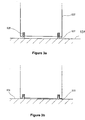
- a set of four spring-loaded castor wheel arrangements are incorporated into the base of the washing machine body 125, being arranged with one in each corner.
- the spring loaded castor wheel arrangements each comprise a castor wheel 127, the top end of which is connected to a strong compressible spring 129 that sits within, and maybe fixed to, the top inner face of a substantially vertical hole, recessed in the base of the washing machine body 125.
- Castor wheels are stated by way of example and may be replaced by any transport means that are not directionally fixed, to increase the manoeuvrability of the washing machine.
- each spring is such that when the ballast of the machine is empty the castor wheels 127 protrude from the base of the washing machine body 125 and are in communication with the floor 131 , allowing the machine to be easily movable across the floor 131 (as shown in Figure 3a ).
- the extra weight compresses the springs 129 such that the machine drops downwardly towards the floor 131 and engages the floor 131 with four protruding rubber studs 133 (see Figure 3b ).
- springs 129 are stated for use in the system, it should be noted that any means that provides a similar action maybe used alternatively or in combination.
- a set of rubber, (or any material with a reasonable coefficient of friction), studs 133 are provided on the base of the machine, to provide friction that opposes any lateral movement generated when the machine is in use.
- the ballast When it is required to move the washing machine, the ballast maybe drained, thereby reducing the overall weight acting on the springs 129 and as such the wheels 127 deploy from the base of the washing machine body 125 causing the washing machine body to raise from the floor 131 (and with it the rubber studs 133) so that the machine maybe freely 'wheeled' to its desired position.
- each castor wheel 127 is independently spring-loaded, it allows for any uneven areas in the floor to be compensated for, both when moving the machine and when it is stationary.
- the system described could be replaced by having a common connection between the four castor wheels 127 that is itself spring loaded, but this would require a stronger spring and reduce the ability to compensate for uneven surfaces.
Landscapes
- Engineering & Computer Science (AREA)
- Textile Engineering (AREA)
- Detail Structures Of Washing Machines And Dryers (AREA)
- Main Body Construction Of Washing Machines And Laundry Dryers (AREA)
- Washing And Drying Of Tableware (AREA)
- Control Of Washing Machine And Dryer (AREA)
Applications Claiming Priority (7)
| Application Number | Priority Date | Filing Date | Title |
|---|---|---|---|
| GB0523974A GB2432644A (en) | 2005-11-25 | 2005-11-25 | Extendable drive linkage |
| GB0523981A GB2432593A (en) | 2005-11-25 | 2005-11-25 | Washing machine drum |
| GB0523980A GB2432577A (en) | 2005-11-25 | 2005-11-25 | Dispensing apparatus |
| GBGB0523978.5A GB0523978D0 (en) | 2005-11-25 | 2005-11-25 | Water supply for laundry appliances |
| GB0612666A GB2439565A (en) | 2006-06-27 | 2006-06-27 | Programmable control device for an appliance. |
| GB0613782A GB2432594A (en) | 2005-11-25 | 2006-07-12 | Ballast system for a washing machine |
| EP06808674A EP1996755A2 (fr) | 2005-11-25 | 2006-11-24 | Appareil de lavage |
Related Parent Applications (1)
| Application Number | Title | Priority Date | Filing Date |
|---|---|---|---|
| EP06808674.3 Division | 2006-11-24 |
Publications (2)
| Publication Number | Publication Date |
|---|---|
| EP2428606A2 true EP2428606A2 (fr) | 2012-03-14 |
| EP2428606A3 EP2428606A3 (fr) | 2012-07-04 |
Family
ID=39878012
Family Applications (3)
| Application Number | Title | Priority Date | Filing Date |
|---|---|---|---|
| EP11188132A Withdrawn EP2420608A1 (fr) | 2005-11-25 | 2006-11-24 | Appareil de lavage |
| EP06808674A Withdrawn EP1996755A2 (fr) | 2005-11-25 | 2006-11-24 | Appareil de lavage |
| EP11188127A Withdrawn EP2428606A3 (fr) | 2005-11-25 | 2006-11-24 | Appareil de lavage |
Family Applications Before (2)
| Application Number | Title | Priority Date | Filing Date |
|---|---|---|---|
| EP11188132A Withdrawn EP2420608A1 (fr) | 2005-11-25 | 2006-11-24 | Appareil de lavage |
| EP06808674A Withdrawn EP1996755A2 (fr) | 2005-11-25 | 2006-11-24 | Appareil de lavage |
Country Status (4)
| Country | Link |
|---|---|
| US (2) | US20100162774A1 (fr) |
| EP (3) | EP2420608A1 (fr) |
| JP (1) | JP2009517111A (fr) |
| WO (1) | WO2007060455A2 (fr) |
Families Citing this family (10)
| Publication number | Priority date | Publication date | Assignee | Title |
|---|---|---|---|---|
| KR101136863B1 (ko) | 2007-02-28 | 2012-04-20 | 삼성전자주식회사 | 세탁기 |
| EP2003237B1 (fr) | 2007-06-12 | 2016-05-04 | Electrolux Home Products Corporation N.V. | Distributeur de produits détergents pour un lave-linge |
| CH703349B1 (de) * | 2010-06-29 | 2013-12-13 | V Zug Ag | Waschmaschine mit Waschmittel-Dosiervorrichtung. |
| KR20120004208A (ko) * | 2010-07-06 | 2012-01-12 | 삼성전자주식회사 | 세제공급장치 및 이를 가지는 세탁기 |
| US20120144878A1 (en) * | 2010-12-13 | 2012-06-14 | Alaknanda Acharya | Device for dispensing an additive in an appliance |
| EP2756127B1 (fr) * | 2011-09-14 | 2021-10-27 | Ecolab USA Inc. | Dosiervorrichtung und verfahren zur dosierung mindestens eines fluids |
| KR101500186B1 (ko) * | 2013-11-06 | 2015-03-06 | 동부대우전자 주식회사 | 드럼 세탁기 |
| JP6286662B2 (ja) * | 2013-11-26 | 2018-03-07 | パナソニックIpマネジメント株式会社 | 洗濯機 |
| US10815606B2 (en) * | 2018-03-01 | 2020-10-27 | Haier Us Appliance Solutions, Inc. | Washing machine appliance with smart dispense |
| CN115067805B (zh) * | 2022-04-29 | 2025-09-16 | 深圳银星智能集团股份有限公司 | 清洁系统 |
Family Cites Families (39)
| Publication number | Priority date | Publication date | Assignee | Title |
|---|---|---|---|---|
| US1751982A (en) * | 1924-11-15 | 1930-03-25 | Whirldry Corp | Washing and drying machine |
| US1847159A (en) * | 1928-10-25 | 1932-03-01 | Troy Laundry Machinery Co | Extractor |
| US2637189A (en) * | 1947-09-20 | 1953-05-05 | Easy Washing Machine Corp | Laundry machine |
| US2641918A (en) * | 1949-06-03 | 1953-06-16 | Maytag Co | Washing machine with rotatable tub having a centrifugally operated valve |
| US2748788A (en) * | 1951-04-28 | 1956-06-05 | Maytag Co | Centrifugally operated valve |
| US2720089A (en) * | 1952-12-05 | 1955-10-11 | Admiral Corp | Refrigerator tray and baffle |
| US2775883A (en) * | 1953-03-30 | 1957-01-01 | Whirlpool Seeger Corp | Centrifugal extracting and washing machine |
| US2764884A (en) * | 1953-07-14 | 1956-10-02 | Arthur R Constantine | Washing machine |
| GB1027671A (en) * | 1961-08-08 | 1966-04-27 | English Electric Co Ltd | Improvements in or relating to domestic laundering appliances |
| US3283547A (en) * | 1964-03-02 | 1966-11-08 | Whirlpool Co | Speed control for a laundry machine |
| US3349582A (en) * | 1965-07-23 | 1967-10-31 | Richard E Quinn | Rotatable drum and drain valve therefor |
| GB1160274A (en) * | 1965-12-22 | 1969-08-06 | English Electric Co Ltd | Improvements in or relating to Domestic Appliances |
| GB1240034A (en) * | 1968-02-13 | 1971-07-21 | Ind A Zannussi S P A | A washing machine |
| AT284760B (de) * | 1968-02-13 | 1970-09-25 | Zanussi A Spa Industrie | Vorrichtung zur Stabilisierung des Standes bzw. zur Erhöhung der Standfestigkeit einer Waschmaschine od.dgl. |
| US3982666A (en) * | 1971-12-22 | 1976-09-28 | Economics Laboratory, Inc. | Fine timing apparatus for electronic detergent dispensing system |
| US3826408A (en) * | 1973-06-29 | 1974-07-30 | A Freyberger | Gravity flow portable laundry liquid dispenser |
| CA985926A (en) * | 1973-08-03 | 1976-03-23 | Canbar Products Limited | Spiral drain scoop for rotating drum |
| AT352485B (de) * | 1974-06-29 | 1979-09-25 | Chivari Ilie | Kupplung zum kuppeln achsversetzter umlaufender wellen |
| FR2626588B1 (fr) * | 1988-01-28 | 1991-04-26 | Martinez Georges | Machine a laver le linge dont la cuve est equipee d'elements de lestage |
| US5188150A (en) * | 1988-06-09 | 1993-02-23 | Esplin Trevor T | Valve assembly |
| US5007254A (en) * | 1989-12-28 | 1991-04-16 | Raytheon Company | Additive fluid viewing |
| FR2660455A1 (fr) * | 1990-04-03 | 1991-10-04 | Chabard Paul | Procede et dispositif d'alimentation d'un compartiment en produits de traitement notamment d'une machine a laver le linge. |
| IT1247623B (it) * | 1990-08-30 | 1994-12-28 | Zanussi Elettrodomestici | Dispositivo dosatore di detersivi liquidi per macchine lavatrici |
| IT1260451B (it) * | 1992-01-27 | 1996-04-09 | Smeg Spa | Contenitore per detersivi ed addittivi liquidi da utilizzare in macchine domestiche di lavaggio e macchine provviste di tale contenitore |
| US5870906A (en) * | 1996-04-03 | 1999-02-16 | Denisar; Richard A. | Automatic dispensing device |
| DE19651292C2 (de) * | 1996-12-10 | 2003-03-20 | Bsh Bosch Siemens Hausgeraete | Haushaltsgerät mit mindestens einem lösbar angeordneten Funktionsteil |
| DE29705226U1 (de) * | 1997-03-22 | 1998-07-23 | AEG Hausgeräte GmbH, 90429 Nürnberg | Waschtrommel für eine Waschmaschine |
| DE19905534B4 (de) * | 1999-02-10 | 2010-02-04 | BSH Bosch und Siemens Hausgeräte GmbH | Trommelwaschmaschine mit einer Wäschetrommel, deren Trommelmantel eine strukturierte Oberfläche aufweist |
| TW470801B (en) * | 1999-03-31 | 2002-01-01 | Toshiba Corp | Drum type washing machine |
| JP2001157788A (ja) * | 1999-12-02 | 2001-06-12 | Matsushita Electric Ind Co Ltd | 洗濯機 |
| JP2001162083A (ja) * | 1999-12-10 | 2001-06-19 | Matsushita Electric Ind Co Ltd | 洗濯機 |
| FR2828503B1 (fr) * | 2001-08-08 | 2003-10-31 | Georges Mathias Martinez | Machine a laver et a essorer a concept de cuve recyclant l'eau |
| EP1285986B1 (fr) * | 2001-08-14 | 2004-07-28 | CANDY S.p.A. | Machine à laver améliorée |
| JP2003164695A (ja) * | 2001-11-30 | 2003-06-10 | Matsushita Electric Ind Co Ltd | 洗濯機 |
| DE10162918A1 (de) * | 2001-12-20 | 2003-07-03 | Bsh Bosch Siemens Hausgeraete | Trommel für eine Wäschebehandlungsmaschine |
| US7036175B2 (en) * | 2002-02-19 | 2006-05-02 | Maytag Corporation | Washing machine with pay activated bulk detergent dispenser |
| CN100437738C (zh) * | 2004-02-23 | 2008-11-26 | 鸿富锦精密工业(深圳)有限公司 | 具有多功能按钮的多媒体设备及其处理方法 |
| KR101075223B1 (ko) * | 2004-11-29 | 2011-10-19 | 삼성전자주식회사 | 드럼세탁기 및 그 제어방법 |
| KR20070017732A (ko) * | 2005-08-08 | 2007-02-13 | 삼성전자주식회사 | 드럼 세탁기 |
-
2006
- 2006-11-24 EP EP11188132A patent/EP2420608A1/fr not_active Withdrawn
- 2006-11-24 WO PCT/GB2006/004406 patent/WO2007060455A2/fr not_active Ceased
- 2006-11-24 EP EP06808674A patent/EP1996755A2/fr not_active Withdrawn
- 2006-11-24 US US12/094,930 patent/US20100162774A1/en not_active Abandoned
- 2006-11-24 EP EP11188127A patent/EP2428606A3/fr not_active Withdrawn
- 2006-11-24 JP JP2008541826A patent/JP2009517111A/ja active Pending
-
2011
- 2011-03-25 US US13/072,043 patent/US20110167877A1/en not_active Abandoned
Non-Patent Citations (1)
| Title |
|---|
| None |
Also Published As
| Publication number | Publication date |
|---|---|
| EP2420608A1 (fr) | 2012-02-22 |
| JP2009517111A (ja) | 2009-04-30 |
| EP2428606A3 (fr) | 2012-07-04 |
| US20110167877A1 (en) | 2011-07-14 |
| WO2007060455A3 (fr) | 2007-12-21 |
| WO2007060455A2 (fr) | 2007-05-31 |
| US20100162774A1 (en) | 2010-07-01 |
| EP1996755A2 (fr) | 2008-12-03 |
Similar Documents
| Publication | Publication Date | Title |
|---|---|---|
| EP1959045B1 (fr) | Machine à laver avec un distributeur d'agents de nettoyage liquides | |
| US12320056B2 (en) | Bulk dispenser for a laundry treating appliance | |
| JPH01308595A (ja) | バラスト部品を備えた電気洗濯機 | |
| RU2651482C2 (ru) | Устройство для обработки паром | |
| CN114745990B (zh) | 全自动电饭锅装置 | |
| CN105143543A (zh) | 洗衣机 | |
| GB2432594A (en) | Ballast system for a washing machine | |
| CN203524458U (zh) | 全自动快餐加工设备 | |
| CN209284984U (zh) | 一种自动供热水的烹饪装置和自动烹饪器具 | |
| JP2009517111A5 (fr) | ||
| MXPA04009166A (es) | Calentador de agua electrico que tiene calentamiento de agua con densidad de vatiaje balanceada. | |
| JP2009517111A (ja) | 洗浄機器 | |
| US20120192596A1 (en) | Actuation Mechanism Configured to Exert Mechanical Forces on Laundry Items in a Wash Basin | |
| KR101781951B1 (ko) | 음용수기용 복합형 온수통 구조 | |
| US11028521B2 (en) | Fabric treating appliance comprising a bulk dispenser | |
| TWM459824U (zh) | 沖茶機 | |
| KR20120138143A (ko) | 높이조절이 가능한 휴대용 떡 찜 장치 | |
| US5535774A (en) | Apparatus for storing and supplying water for use in catering equipment | |
| KR20190098943A (ko) | 의류처리장치 | |
| CN108662358A (zh) | 一种调平装置、具有该调平装置的洗衣机及其控制方法 | |
| CN107647781A (zh) | 一种便捷式泡茶设备 | |
| EP3988696B1 (fr) | Appareil de traitement du linge comportant plusieurs récipients de composition de traitement | |
| WO2016108791A1 (fr) | Lave-vaisselle | |
| KR20120113044A (ko) | 보일러용 체크 밸브 및 이를 포함한 보일러 | |
| CN212870647U (zh) | 一种芍药翻炒设备 |
Legal Events
| Date | Code | Title | Description |
|---|---|---|---|
| 17P | Request for examination filed |
Effective date: 20111108 |
|
| AC | Divisional application: reference to earlier application |
Ref document number: 1996755 Country of ref document: EP Kind code of ref document: P |
|
| AK | Designated contracting states |
Kind code of ref document: A2 Designated state(s): AT BE BG CH CY CZ DE DK EE ES FI FR GB GR HU IE IS IT LI LT LU LV MC NL PL PT RO SE SI SK TR |
|
| PUAI | Public reference made under article 153(3) epc to a published international application that has entered the european phase |
Free format text: ORIGINAL CODE: 0009012 |
|
| PUAL | Search report despatched |
Free format text: ORIGINAL CODE: 0009013 |
|
| AK | Designated contracting states |
Kind code of ref document: A3 Designated state(s): AT BE BG CH CY CZ DE DK EE ES FI FR GB GR HU IE IS IT LI LT LU LV MC NL PL PT RO SE SI SK TR |
|
| RIC1 | Information provided on ipc code assigned before grant |
Ipc: D06F 39/00 20060101ALI20120530BHEP Ipc: D06F 37/26 20060101AFI20120530BHEP |
|
| RIC1 | Information provided on ipc code assigned before grant |
Ipc: D06F 39/00 20060101ALI20130528BHEP Ipc: D06F 37/26 20060101AFI20130528BHEP |
|
| STAA | Information on the status of an ep patent application or granted ep patent |
Free format text: STATUS: THE APPLICATION IS DEEMED TO BE WITHDRAWN |
|
| 18D | Application deemed to be withdrawn |
Effective date: 20130601 |