EP2428639A2 - Anordnung aus einer Isolationshülse und gebündelten Hülsen mit Druckkammern - Google Patents
Anordnung aus einer Isolationshülse und gebündelten Hülsen mit Druckkammern Download PDFInfo
- Publication number
- EP2428639A2 EP2428639A2 EP11250752A EP11250752A EP2428639A2 EP 2428639 A2 EP2428639 A2 EP 2428639A2 EP 11250752 A EP11250752 A EP 11250752A EP 11250752 A EP11250752 A EP 11250752A EP 2428639 A2 EP2428639 A2 EP 2428639A2
- Authority
- EP
- European Patent Office
- Prior art keywords
- sleeve
- sliding sleeve
- tubing string
- sliding
- wellbore
- Prior art date
- Legal status (The legal status is an assumption and is not a legal conclusion. Google has not performed a legal analysis and makes no representation as to the accuracy of the status listed.)
- Withdrawn
Links
Images





Classifications
-
- E—FIXED CONSTRUCTIONS
- E21—EARTH OR ROCK DRILLING; MINING
- E21B—EARTH OR ROCK DRILLING; OBTAINING OIL, GAS, WATER, SOLUBLE OR MELTABLE MATERIALS OR A SLURRY OF MINERALS FROM WELLS
- E21B34/00—Valve arrangements for boreholes or wells
- E21B34/06—Valve arrangements for boreholes or wells in wells
- E21B34/10—Valve arrangements for boreholes or wells in wells operated by control fluid supplied from outside the borehole
-
- E—FIXED CONSTRUCTIONS
- E21—EARTH OR ROCK DRILLING; MINING
- E21B—EARTH OR ROCK DRILLING; OBTAINING OIL, GAS, WATER, SOLUBLE OR MELTABLE MATERIALS OR A SLURRY OF MINERALS FROM WELLS
- E21B23/00—Apparatus for displacing, setting, locking, releasing or removing tools, packers or the like in boreholes or wells
- E21B23/04—Apparatus for displacing, setting, locking, releasing or removing tools, packers or the like in boreholes or wells operated by fluid means, e.g. actuated by explosion
- E21B23/0412—Apparatus for displacing, setting, locking, releasing or removing tools, packers or the like in boreholes or wells operated by fluid means, e.g. actuated by explosion characterised by pressure chambers, e.g. vacuum chambers
-
- E—FIXED CONSTRUCTIONS
- E21—EARTH OR ROCK DRILLING; MINING
- E21B—EARTH OR ROCK DRILLING; OBTAINING OIL, GAS, WATER, SOLUBLE OR MELTABLE MATERIALS OR A SLURRY OF MINERALS FROM WELLS
- E21B34/00—Valve arrangements for boreholes or wells
- E21B34/06—Valve arrangements for boreholes or wells in wells
- E21B34/14—Valve arrangements for boreholes or wells in wells operated by movement of tools, e.g. sleeve valves operated by pistons or wire line tools
- E21B34/142—Valve arrangements for boreholes or wells in wells operated by movement of tools, e.g. sleeve valves operated by pistons or wire line tools unsupported or free-falling elements, e.g. balls, plugs, darts or pistons
-
- E—FIXED CONSTRUCTIONS
- E21—EARTH OR ROCK DRILLING; MINING
- E21B—EARTH OR ROCK DRILLING; OBTAINING OIL, GAS, WATER, SOLUBLE OR MELTABLE MATERIALS OR A SLURRY OF MINERALS FROM WELLS
- E21B43/00—Methods or apparatus for obtaining oil, gas, water, soluble or meltable materials or a slurry of minerals from wells
- E21B43/14—Obtaining from a multiple-zone well
-
- E—FIXED CONSTRUCTIONS
- E21—EARTH OR ROCK DRILLING; MINING
- E21B—EARTH OR ROCK DRILLING; OBTAINING OIL, GAS, WATER, SOLUBLE OR MELTABLE MATERIALS OR A SLURRY OF MINERALS FROM WELLS
- E21B43/00—Methods or apparatus for obtaining oil, gas, water, soluble or meltable materials or a slurry of minerals from wells
- E21B43/25—Methods for stimulating production
- E21B43/26—Methods for stimulating production by forming crevices or fractures
-
- E—FIXED CONSTRUCTIONS
- E21—EARTH OR ROCK DRILLING; MINING
- E21B—EARTH OR ROCK DRILLING; OBTAINING OIL, GAS, WATER, SOLUBLE OR MELTABLE MATERIALS OR A SLURRY OF MINERALS FROM WELLS
- E21B2200/00—Special features related to earth drilling for obtaining oil, gas or water
- E21B2200/06—Sleeve valves
Definitions
- a frac assembly down the wellbore.
- the assembly has a top liner packer, open hole packers isolating the wellbore into zones, various sliding sleeves, and a wellbore isolation valve.
- operators may use single shot sliding sleeves for the frac treatment.
- These types of sleeves are usually ball-actuated and lock open once actuated.
- Another type of sleeve is also ball-actuated, but can be shifted closed after opening.
- the lowermost sliding sleeve has a ball seat for the smallest sized ball size, and successively higher sleeves have larger seats for larger balls. In this way, a specific sized dropped ball will pass though the seats of upper sleeves and only locate and seal at a desired seat in the tubing string.
- practical limitations restrict the number of balls that can be run in a single tubing string.
- operators may need a more versatile assembly that can suit their immediate needs.
- the subject matter of the present disclosure is directed to overcoming, or at least reducing the effects of, one or more of the problems set forth above.
- a wellbore fluid treatment method comprising: deploying a plurality of sliding sleeves on a tubing string in a wellbore annulus, the sliding sleeves at least including a first sliding sleeve and at least one second sliding sleeve; opening the first sliding sleeve to communicate fluid pressure from the tubing string to the wellbore annulus by deploying a first plug down the tubing string and pumping fluid pressure in the tubing string; and opening the at least one second sliding sleeve by applying fluid pressure in the wellbore annulus relative to a pressure chamber on the at least one second sliding sleeve.
- Deploying the plurality of sliding sleeves may comprise isolating the wellbore annulus uphole and downhole of the plurality of sliding sleeves on the tubing string.
- Isolating the wellbore annulus may comprise engaging packing elements on the tubing string uphole and downhole of the sliding sleeves against a sidewall of the wellbore.
- Deploying the sliding sleeves may comprise deploying the at least one second sliding sleeve uphole of the first sliding sleeve on the tubing string.
- Deploying the sliding sleeves may comprise deploying the at least one second sliding sleeve uphole of the first sliding sleeve on the tubing string.
- the first sliding sleeve may comprise: a movable sleeve being movable from a closed condition to an open condition relative to an outlet; and a seat disposed on the movable sleeve and engaging with the first plug when deployed down the tubing string, the movable sleeve moving to the open condition in response to fluid pressure applied against the seated first plug.
- the at least one second sliding sleeve may comprise: a movable sleeve being movable from a closed condition to an open condition relative to an outlet, the movable sleeve moving from the closed condition to the open condition in response to a pressure differential between the wellbore annulus and the pressure chamber, the movable sleeve in the open condition permitting fluid pressure from the tubing string to communicate to the wellbore annulus through the outlet.
- Opening the first sliding sleeve to communicate fluid pressure from the tubing string with the wellbore annulus may comprise: engaging the deployed first plug on a seat of a movable sleeve of the first sliding sleeve; and moving the movable sleeve open relative to an outlet of the first sliding sleeve with fluid pressure applied against the seated first plug.
- Opening the at least on second sliding sleeve may comprise: creating a pressure differential between the wellbore annulus and the pressure chamber of a movable sleeve on the at least one second sliding sleeve; and moving the movable sleeve open relative to an outlet on the at least one second sliding sleeve in response to the created pressure differential.
- Creating the pressure differential may comprise applying the fluid pressure in the wellbore annulus against the movable sleeve to act against the pressure chamber.
- Deploying the sliding sleeves may comprise deploying a third sliding sleeve and at least one fourth sliding sleeve uphole from the first sliding sleeve and the at least one second sliding sleeve.
- Deploying the sliding sleeves may comprises isolating the third sliding sleeve and the at least one fourth sliding sleeves from the first sliding sleeve and the at least one second sliding sleeve in the wellbore annulus.
- the method may further comprise: opening the third sliding sleeve to communicate fluid pressure from the tubing string to the wellbore annulus by deploying a second plug down the tubing string and pumping fluid pressure in the tubing string; and opening the at least one fourth sliding sleeve by applying fluid pressure in the wellbore annulus relative to a pressure chamber on the at least one fourth sliding sleeve.
- the tubing string may comprise a plurality of the at least one second sliding sleeves, each of the second sliding sleeves having a pressure chamber and each opening in response to a same or different pressure differential between the wellbore annulus and the pressure chamber.
- a wellbore fluid treatment method comprising: deploying at least one first sliding sleeve on a tubing string in a wellbore annulus, the at least one first sliding sleeve having a pressure chamber; increasing fluid pressure in the wellbore annulus; applying the fluid pressure in the wellbore annulus relative to the pressure chamber on the at least one first sliding sleeve; and opening the at least one first sliding sleeve with a pressure differential between the pressure chamber and the wellbore annulus.
- a wellbore fluid treatment method comprising: deploying a plurality of sliding sleeves on a tubing string in a wellbore annulus, the sliding sleeves at least including a first sliding sleeve and at least one second sliding sleeve; seating a plug in the first sliding sleeve; pumping fluid pressure in the tubing string; opening the first sliding sleeve with fluid pressure applied against the seated plug in the first sliding sleeve; communicating fluid pressure to the wellbore annulus through the open first sliding sleeve; applying fluid pressure in the wellbore annulus relative to a pressure chamber on the at least one second sliding sleeve; and opening the at least one second sliding sleeve with a pressure differential between the pressure chamber and the wellbore annulus.
- a wellbore fluid treatment apparatus comprising: a first sliding sleeve disposing on a tubing string in a wellbore and opening in response to fluid pressure applied down the tubing string, the open first sliding sleeve communicating fluid pressure from the tubing string to a wellbore annulus through a first outlet on the first sliding sleeve; and a second sliding sleeve disposing on the tubing string in the wellbore and having a pressure chamber, the second sliding sleeve opening in response to a pressure differential between the wellbore annulus and the pressure chamber, the open second sliding sleeve communicating fluid pressure from the tubing string to the wellbore annulus through a second outlet on the second sliding sleeve.
- the apparatus may further comprise at least one packing element disposing on the tubing string in the wellbore, the at least one packing element isolating the wellbore annulus around the first and second sliding sleeves from other portions of the wellbore.
- the first sliding sleeve may comprise: a movable sleeve being movable from a closed condition to an open condition relative to the first outlet; and a seat disposed on the movable sleeve and engaging with a plug when deployed down the tubing string, the movable sleeve moving to the open condition in response to fluid pressure applied against the seated plug.
- the second sliding sleeve may be disposed uphole of the first sliding sleeve on the tubing string.
- the at least one second sliding sleeve may comprise: a movable sleeve being movable from a closed condition to an open condition relative to the second outlet, the movable sleeve moving from the closed condition to the open condition in response to the pressure differential between the wellbore annulus and the pressure chamber, the movable sleeve in the open condition permitting fluid pressure from the tubing string to communicate to the wellbore annulus through the second outlet.
- the pressure chamber may be defined between the movable sleeve and a housing portion of the at least one second sliding sleeve.
- the fluid pressure in the wellbore annulus may act against the movable sleeve.
- the movable sleeve may comprise an internal sleeve movably disposed in a bore of a housing of the second sliding sleeve, the housing defining the second outlet.
- the movable sleeve may comprise an external sleeve movably disposed on a housing of the second sliding sleeve, the housing defining the second outlet.
- the apparatus may further comprise at least one third sliding sleeve disposing on the tubing string in the wellbore and having another pressure chamber, the at least one third sliding sleeve opening in response to a same or different pressure differential between the wellbore annulus and the pressure chamber.
- sliding sleeves deploy on a tubing string in a wellbore annulus.
- the tubing string has packing elements disposed thereon.
- the tubing string has a first isolation sleeve and one or more second cluster sleeves disposed between the packing elements.
- the isolation sleeve can be disposed downhole of the one or more second cluster sleeves on the tubing sting or in some other arrangement.
- the fluid pressure produces a pressure differential between the wellbore annulus pressure and the pressure chambers on the cluster sleeves disposed on the tubing string.
- the pressure differential between the pressure chambers and the wellbore annulus then opens the cluster sleeves so that fluid pressure from the tubing string can communicate through these open sleeves.
- one isolation sleeve can be opened in a cluster of sleeves without opening all of them at the same time.
- the ball is not required to open each sleeve of the cluster. Instead, the ball is only required to open the tubing pressure to the annulus by opening the isolation sleeve. Then, the pressure chambers actuate the cluster sleeves to open up more of the tubing string to the surrounding annulus.
- the fluid pressure after the isolation sleeve has been opened travels down the tubing string and into the isolated annulus of the zone.
- the cluster sleeves with their pressure chambers are set to withstand the hydrostatic pressure downhole within an acceptable margin. Yet, fluid pressure in the wellbore annulus equalizes with the tubing string's pressure.
- the pressure chambers on the cluster sleeves are actuated by the applied pressure in the annulus, and the cluster sleeves shift open so more of the isolated zone can be treated because the pressure chambers have a lower pressure.
- each cluster sleeve in the isolated zone can be configured to open at specified pressures that can be different from or the same as other clusters sleeves in the isolated zone. Operators can ensure all of the sliding sleeves open for maximum coverage per zone and can tailor the opening according to particular purposes.
- Fig. 1 diagrammatically illustrates a tubing string having multiple sliding sleeves according to the present disclosure.
- Fig. 2 shows a cross-section of one arrangement of sliding sleeves on a tubing string according to the present disclosure.
- Figs. 3A-3B show portions of the tubing string of Fig. 2 , revealing details of the cluster sleeves.
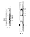
- Fig. 3C show another portion of the tubing string of Fig. 2 , revealing details of the isolation sleeve.
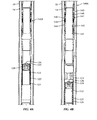
- Figs. 4A-4C show portions of the tubing string of Fig. 2 in stages of opening.
- Fig. 5 shows a cross-section of another arrangement of sliding sleeves on a tubing string according to the present disclosure.
- Figs. 6A-6B show portions of the tubing string of Fig. 5 , revealing details of the cluster sleeves.
- Fig. 6C show another portion of the tubing string of Fig. 5 , revealing details of the isolation sleeve.
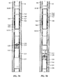
- Figs. 7A-7C show portions of the tubing string of Fig. 5 in stages of opening.
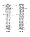
- Figs. 8A-8B diagrammatically illustrate a tubing string having alternate arrangements of sliding sleeves according to the present disclosure.
- a tubing string 110 shown in Figure 1 deploys in a wellbore 10.
- the string 110 has an isolation sliding sleeve 120 and cluster sliding sleeves 130A-B disposed along its length.
- a pair of packing elements or other isolation devices 114A-B isolate portion of the wellbore 10 into an isolated zone.
- the sliding sleeves 120 and 130A-B can divert treatment fluid to the isolated zone of the surrounding formation.
- the treatment fluid can be frac fluid having proppant pumped at high pressure or can be other suitable type of fluid (with or without additive) to treat a zone of the wellbore.
- the tubing string 110 can be part of a frac assembly 20, for example, having a top liner packer (not shown), a wellbore isolation valve (not shown), and other packers and sliding sleeves (not shown) in addition to those shown.
- the tubing string 110 can be part of a completion assembly or other suitable assembly.
- the wellbore 10 can be an opened or cased hole, and the packing elements 114A-B can be any suitable type of element or packer intended to isolate portions of the wellbore into isolated zones.
- the wellbore 10 can be an open hole, or can have a casing. If a cased hole, the wellbore 10 can have casing perforations 16 at various points as shown.
- a fracing assembly 20 For example, operators deploy a setting ball to close a wellbore isolation valve (not shown) downhole, rig up fracing surface equipment (e.g. , pump system 35 and the like), pump fluid down the wellbore, and open a pressure actuated sleeve (not shown) downhole so a first zone can be treated.
- rig up fracing surface equipment e.g. , pump system 35 and the like
- a pressure actuated sleeve not shown
- the isolation sleeve 120 has a seat (not shown).
- a specifically sized plug e.g. , ball, dart, or the like
- the plug engages the isolation sleeve's seat.
- the plug is described as a ball, although the plug can be any other acceptable device.
- the seated ball opens the isolation sleeve 120 so the pumped fluid can be diverted out ports to the surrounding wellbore 10 between the packers 114A-B.
- the cluster sleeves 130A-B have pressure chambers (not shown) according to the present disclosure, which are described in more detail later. These pressure chambers are at low or atmospheric pressure, but are configured to withstand the hydrostatic pressure expected at the particular depth downhole.
- the specifically sized ball is dropped down the tubing string 110 to engage the isolation sleeve 120, the dropped ball passes through the cluster sleeves 130A-B without opening them.
- the isolation sleeve 120 is opened, however, the fluid pressure pumped down the tubing string 110 enters the isolated annulus 14 of the wellbore 10 and creates a pressure differential between the wellbore annulus and the pressure chambers of the cluster sleeves 130A-B.
- the cluster sleeves 130A-B are activated by the pressure differential against their pressure chambers and any shear pins or other temporary retaining features. Eventually, the cluster sleeves 130A-B open and allow the communicated fluid in the tubing string 110 to enter the isolated annulus 14 through the open ports of these cluster sleeves 130A-B. In this way, one sized ball can be dropped down the tubing string 110 past a cluster of sliding sleeves 130A-B to treat an isolated zone.
- the sleeves 120 and 130A-B can divert the fluid pressure along the length of the tubing string 110 and at particular points in the wellbore 10. For example, the particular points can be adjacent certain perforations 16 if the wellbore 10 has casing 12, or they can be certain areas of the open hole if uncased.
- One arrangement of a tubing string 110 shown in Figure 2 defines a through-bore 112 and has packing elements 114A-B on both ends. Although shown as packing sleeves, these elements 114A-B can be any suitable type of packing or sealing element, either active or passive, known in the art.
- the string 110 has an isolation sleeve 120. Uphole from this, the string 110 has one or more cluster sleeves 140A-B. Although two cluster sleeves 140A-B are shown in this example, the string 110 may have any number.
- the isolation sleeve 120 shown in detail in Figure 3C has an internal sleeve or insert 122 movably disposed in a housing 121 that forms part of the tubing string 110.
- This internal sleeve 122 can move relative to external ports 123 in bore of the housing 121.
- a seat 124 on the internal sleeve 122 engages with a dropped ball 126 or other type of plug when deployed from uphole.
- the cluster sleeves 140A-B shown in Figures 3A-3B each have an internal sleeve or insert 142 movably disposed in a housing 141 that forms part of the tubing string 110.
- the housing 141 has upper, lower, and intermediate portions that couple together, which facilitates assembly.
- the internal sleeve 142 can move relative to external ports 143 in a bore of the housing 141.
- the internal sleeve 142 defines a first (hydrostatic pressure) chamber 144 isolated from a second chamber 146 by a seal ring 125.
- the first chamber 144 is closed and is at a low or preset pressure, such as atmospheric.
- the second chamber 146 communicates with an inlet port 147 communicating with the annulus surrounding the string 12.
- Shear pins 148 hold the internal sleeve 142 in its closed condition covering the external ports 143.
- Figures 4A-4C show portions of the tubing string 110 in stages of opening. Initially, the isolation sleeve 120 and cluster sleeves (only one 140A shown) deploy downhole in a closed condition as shown in Figure 4A .
- the packing elements (114A-B; Fig. 2A ) engage the surrounding sidewall of the wellbore 10 to isolate a zone of the annulus.
- the dropped ball 126 may pass any number of other arrangements of similar configured sleeves for other isolated zones. However, these other arrangements have isolation sleeves configured to engage larger sized balls 126 or plugs. Therefore, the present ball 126 or plug passes through these uphole isolation sleeves without opening them.
- the dropped ball 126 engages with the isolation sleeve's seat 124 as shown in Figure 4A .
- the seated ball 126 now isolates the uphole portion of the string's bore 112 from any additional components downhole from the present arrangement.
- the fluid pressure in the annulus 14 reaches the inlet port 147 on the cluster sleeve 140A.
- Pressure entering the port 147 fills the second chamber 146 and acts against the seal ring 145 on the sleeve 142.
- This seal ring 145 is affixed to the internal sleeve 142 and has seals engaging both the internal sleeve 142 and housing 141.
- a pressure differential develops between the first and second chambers 144 and 146.
- the fluid pressure breaks the shear pins 148 and forces the internal sleeve 142 downward in the housing 141. This movement reveals the exit ports 143 for the cluster sleeve 140A so that fluid pressure communicated down the tubing string 110 can enter the annulus 14 at the locations of these ports 143.
- one dropped ball 126 or other plug can be used to open multiple sliding sleeves 120/140A-B to treat a length of isolated formation.
- the isolation sleeve 120 is open by engagement of the ball 126 followed by application of fluid pressure.
- the one or more cluster sleeves 140A-B are opened subsequently once the fluid pressure in the isolated annulus 14 activates these sleeves 140A-B to open.
- a number of ways can be used to have the fluid pressure in the isolated annulus 14 activate the pressure chambers 144 of the cluster sleeves 140A-B.
- the previous embodiment used fluid pressure applied through a port 147 in the sleeve's housing 141 to create a pressure differential to move the internal sleeve 142 of the cluster sleeves 140A-B open. Another arrangement is described below with reference to Figures 5 through 7C .
- the tubing string 110 again has a through-bore 112 and packing elements 114A-B as before.
- the tubing string 110 has an isolation sleeve 120 similar to that described previously.
- the string 110 has one or more cluster sleeves 160A-B. Although two cluster sleeves 160A-B are shown in this example, the tubing string 110 may have any number.
- the isolation sleeve 120 shown in detail in Figure 6C has an internal sleeve 122 movably disposed in a housing 121 relative to external ports 123.
- a seat 124 on the internal sleeve 122 engages a dropped ball 126 or other type of plug.
- the cluster sleeves 160A-B shown in Figures 6A-6B each have an internal sleeve 162 and an external sleeve 164.
- the internal sleeve 162 remains fixed between upper and lower ends 161 a-b and defines exit ports 163.
- the housing of the cluster sleeve 160A-B is formed from upper and lower ends 161 a-b and intermediate internal sleeve 162, which facilitates assembly.
- the external sleeve 164 is disposed on the internal sleeve 162 and can move relative to the exit ports 163.
- the external sleeve 164 defines an isolated pressure chamber 166 in the annular space between the internal and external sleeves 162 and 164.
- a sealing sleeve 165 or portion of the lower housing end 161A affixes against the internal sleeve 162 and has sealing elements sealing against the internal and external sleeves 162/164.
- the isolated chamber 166 is sealed and is at a low or preset pressure, such as atmospheric.
- the external sleeve 164 defines a pressure port or shoulder 167 against which pressure can act.
- shear pins 148 hold the external sleeve 164 in its closed condition covering the external ports 163.
- Figures 7A-7C show portions of the disclosed arrangement on the tubing string 110 in stages of opening.
- the isolation sleeve 120 and cluster sleeves (only on 160A shown) deploy downhole in a closed condition as shown in Figure 7A .
- the packing elements (114A-B; Fig. 5 ) engage the surrounding sidewall of the wellbore 10 to isolate a zone of the formation.
- the dropped ball 126 may pass any number of other arrangements of similar configured sleeves for other isolated zones. However, these other arrangements have isolation sleeves configured to engage larger sized balls 126 or plugs. Therefore, the present ball 126 or plug passes through these uphole isolation sleeves without opening them.
- the dropped ball 126 engages the isolation sleeve's seat 124 as shown in Figure 7A .
- the seated ball 126 now isolates any additional components downhole from the present arrangement.
- operators pump fluid down the string's bore 112, and the pressure from the fluid acts against the seated ball 126.
- the holding ring 128, shear pins, or other affixing element break, and the fluid pressure pushes the seated ball 126 and sleeve 122 downhole as shown in Figure 7B .
- the sleeve 122 reveals the external ports 123 in the housing 121 so fluid can enter the well's annulus 14.
- the sleeve 122 reaches its limit, and a dog or lock ring 129 on the sleeve 122 engages in a profile in the housing 121.
- the fluid pressure in the annulus 14 reaches the inlet port 167 on the cluster sleeve 160A.
- Pressure at the port 167 acts against the different sized faces or shoulders that the port 167 has on its uphole and downhole ends.
- the downhole face or shoulder of the port 167 has a greater surface area than the uphole face or shoulder.
- the fluid pressure in the annulus 14 acts against these faces, it tends to push the external sleeve 164 downward relative to the internal sleeve 162 as the pressure differential between the wellbore annulus and pressure chamber 166 builds and acts against the sleeve 164.
- the increasing pressure breaks the shear pins 168, as shown in Figure 7B .
- the fluid pressure forces the external sleeve 164 downward. This movement reveals the exit ports 163 for these cluster sleeves 160A-B so that fluid communicated down the tubing string 110 can exit and enter the annulus 14 at the locations of these ports 163.
- the isolation sleeve 120 disposes downhole of the cluster sleeves 130/140/160 on the tubing string 110.
- the isolation sleeve 120 can be disposed uphole from the one or more cluster sleeves 180A-B in the isolated zone.
- the isolated zone can be treated with the fluid pressure entering the annulus 14, while the seated ball prevents further fluid pressure to communicate down the tubing string 110.
- the cluster sleeve 180A-B can then be configured to open when a desired pressure in the wellbore annulus 14 is reached. At this point, fluid leaving the isolation sleeve 120 can re-enter the tubing string 110 via the one or more cluster sleeves 180A-B, which are now open and acting as a crossover below the isolation sleeve 120.
- a given zone can have an isolation sleeve 120 disposed between uphole and downhole cluster sleeves 180A-B.
- the isolation sleeve 120 can be disposed between uphole and downhole cluster sleeves 180A-B in the isolated zone.
- the uphole cluster sleeve 180A can be configured to open when a desired pressure in the wellbore annulus 14 is reached so more of the isolated zone can be treated.
- the downhole cluster sleeve 180B can be configured to open when a desired pressure in the wellbore annulus 14 is reached. At this point fluid leaving the isolation sleeve 120 can re-enter the tubing string 110 via the downhole cluster sleeve 180B, which is now open and acting as a crossover.
- an isolated zone of a tubing string in a wellbore can have one or more cluster sleeves (140/160/180) disposed thereon along with more than one isolation sleeve (120) as well.
- a tubing string (or an isolated section of a tubing string) in a wellbore can have one or more cluster sleeves (140/160/180) disposed thereon without having an isolating sleeve (120).
- the arrangements of cluster sleeves 130, 140, 160, and 180 in Figures 1 , 2 , 5 , and 8A-8B may lack an isolating sleeve 120 disposed on the string 110.
- fluid pressure is applied to the wellbore annulus by any suitable technique available in the art (e.g. , by using a mechanically shifted sliding sleeve or a ported housing, by pumping fluid pressure down the wellbore annulus, etc.).
- the isolation sleeve 120 in any of Figures 1 , 2 , 5 , and 8A-8B could be a mechanically shifted sliding sleeve, a ported housing, or the like.
- the disclosed sliding sleeves can be used in these and other arrangements.
- the cluster sleeve includes a movable sleeve that can move from a closed condition to an open condition relative to an outlet.
- the movable sleeve can be an internal sleeve or insert ( e.g. , 142; Fig. 3A ) or an external sleeve ( e.g. , 164; Fig. 6A ).
- This movable sleeve (142/162) is set to the closed condition and has a pressure chamber.
- each cluster sleeve 180 can be configured to open in response to a same or different pressure differential compared to the other cluster sleeves on the tubing string.
Landscapes
- Life Sciences & Earth Sciences (AREA)
- Engineering & Computer Science (AREA)
- Geology (AREA)
- Mining & Mineral Resources (AREA)
- Physics & Mathematics (AREA)
- Environmental & Geological Engineering (AREA)
- Fluid Mechanics (AREA)
- General Life Sciences & Earth Sciences (AREA)
- Geochemistry & Mineralogy (AREA)
- Quick-Acting Or Multi-Walled Pipe Joints (AREA)
- Infusion, Injection, And Reservoir Apparatuses (AREA)
Applications Claiming Priority (1)
| Application Number | Priority Date | Filing Date | Title |
|---|---|---|---|
| US12/877,215 US8893810B2 (en) | 2010-09-08 | 2010-09-08 | Arrangement of isolation sleeve and cluster sleeves having pressure chambers |
Publications (2)
| Publication Number | Publication Date |
|---|---|
| EP2428639A2 true EP2428639A2 (de) | 2012-03-14 |
| EP2428639A3 EP2428639A3 (de) | 2015-09-16 |
Family
ID=44862843
Family Applications (1)
| Application Number | Title | Priority Date | Filing Date |
|---|---|---|---|
| EP11250752.0A Withdrawn EP2428639A3 (de) | 2010-09-08 | 2011-09-08 | Anordnung aus einer Isolationshülse und gebündelten Hülsen mit Druckkammern |
Country Status (5)
| Country | Link |
|---|---|
| US (1) | US8893810B2 (de) |
| EP (1) | EP2428639A3 (de) |
| AU (1) | AU2011218631B2 (de) |
| CA (1) | CA2751191C (de) |
| RU (1) | RU2492318C2 (de) |
Cited By (1)
| Publication number | Priority date | Publication date | Assignee | Title |
|---|---|---|---|---|
| CN105986797A (zh) * | 2015-02-13 | 2016-10-05 | 中国石油天然气股份有限公司 | 水平井的分段压裂方法 |
Families Citing this family (24)
| Publication number | Priority date | Publication date | Assignee | Title |
|---|---|---|---|---|
| WO2013110180A1 (en) * | 2012-01-24 | 2013-08-01 | Cramer David S | Downhole valve and latching mechanism |
| GB2535654B (en) * | 2013-10-31 | 2020-09-02 | Halliburton Energy Services Inc | Hydraulic control of borehole tool deployment |
| CN105683486B (zh) * | 2013-11-25 | 2018-04-06 | 哈利伯顿能源服务公司 | 用于井筒工具的密封组合件 |
| EP3097257A4 (de) * | 2014-01-24 | 2017-09-27 | Completions Research AG | Mehrstufiges hochdruckaufbrechsystem mit zählsystem |
| CA2863603C (fr) * | 2014-09-10 | 2015-11-03 | Armor Tools International Inc. | Ceramic rupture dome for pressure control |
| US10316979B2 (en) | 2014-09-10 | 2019-06-11 | Armor Tools International Inc. | Ceramic rupture dome for pressure control |
| US9670751B2 (en) | 2014-09-19 | 2017-06-06 | Weatherford Technology Holdings, Llc | Sliding sleeve having retrievable ball seat |
| US9587464B2 (en) * | 2014-10-02 | 2017-03-07 | Sc Asset Corporation | Multi-stage liner with cluster valves and method of use |
| RU2567905C1 (ru) * | 2014-11-05 | 2015-11-10 | Акционерное общество "Новомет-Пермь" (АО "Новомет-Пермь") | Муфта для многостадийного гидроразрыва пласта |
| US11142989B2 (en) * | 2016-01-20 | 2021-10-12 | China Petroleum & Chemical Corporation | Tool for jet packing and fracturing and tubular column comprising same |
| CN109415929B (zh) | 2016-05-06 | 2022-03-15 | 斯伦贝谢技术有限公司 | 用于在水力压裂地下土壤层期间形成塞的设备 |
| CA2994290C (en) | 2017-11-06 | 2024-01-23 | Entech Solution As | Method and stimulation sleeve for well completion in a subterranean wellbore |
| RU181716U1 (ru) * | 2017-12-27 | 2018-07-26 | Акционерное общество "ОКБ Зенит" АО "ОКБ Зенит" | Муфта гидроразрыва пласта с растворимым седлом |
| AR117438A1 (es) | 2018-12-18 | 2021-08-04 | Schlumberger Technology Bv | Sistema de sensores integrados con enchufe inteligente |
| GB2583166B (en) | 2019-02-07 | 2021-07-21 | Ardyne Holdings Ltd | Improvements in or relating to well abandonment and slot recovery |
| GB2581338B (en) * | 2019-02-07 | 2021-06-09 | Ardyne Holdings Ltd | Well Abandonment Using Drop Ball Valves |
| CA3042542C (en) * | 2019-05-07 | 2020-08-11 | Key Completions Inc. | Apparatus for downhole fracking and a method thereof |
| CA3119124A1 (en) | 2020-05-19 | 2021-11-19 | Schlumberger Canada Limited | Isolation plugs for enhanced geothermal systems |
| RU200716U1 (ru) * | 2020-06-26 | 2020-11-06 | Общество с ограниченной ответственностью "Российская инновационная топливно-энергетическая компания" (ООО "РИТЭК") | Муфта для проведения многостадийного гидроразрыва пласта |
| US12091931B2 (en) | 2021-02-01 | 2024-09-17 | Schlumberger Technology Corporation | Slip system for use in downhole applications |
| WO2023010108A1 (en) * | 2021-07-29 | 2023-02-02 | Schlumberger Technology Corporation | Sliding sleeve for gas lift system |
| AU2022359895B2 (en) * | 2021-10-06 | 2024-05-09 | Baker Hughes Oilfield Operations Llc | Dual string gas injection system with flow control |
| US12460522B2 (en) | 2022-05-17 | 2025-11-04 | Sc Asset Corporation | Collet baffle, a tool incorporating same, and a system and method incorporating same, for perforating and fracking a wellbore not having initial ports or sliding sleeves |
| US12442269B2 (en) | 2024-01-18 | 2025-10-14 | Progressive Tool Design Inc. | Packerless fracking tool, system, piping assembly and method using continuous tubing for opening infinite stages of sliding sleeves |
Family Cites Families (28)
| Publication number | Priority date | Publication date | Assignee | Title |
|---|---|---|---|---|
| SU794199A1 (ru) | 1978-12-26 | 1981-01-07 | Северо-Кавказский Государственныйнаучно-Исследовательский И Проект-Ный Институт Нефтяной Промышленности | Устройство дл обработки призабойнойзОНы СКВАжиНы |
| US4529038A (en) * | 1982-08-19 | 1985-07-16 | Geo Vann, Inc. | Differential vent and bar actuated circulating valve and method |
| US4520870A (en) | 1983-12-27 | 1985-06-04 | Camco, Incorporated | Well flow control device |
| SU1395809A1 (ru) | 1985-11-01 | 1988-05-15 | Всесоюзный Научно-Исследовательский Институт Буровой Техники | Устройство дл цементировани скважин |
| SU1765367A1 (ru) * | 1986-07-18 | 1992-09-30 | Всесоюзный Научно-Исследовательский Институт Буровой Техники | Муфта дл ступенчатого цементировани обсадных колонн |
| US4823882A (en) | 1988-06-08 | 1989-04-25 | Tam International, Inc. | Multiple-set packer and method |
| US4893678A (en) | 1988-06-08 | 1990-01-16 | Tam International | Multiple-set downhole tool and method |
| US5048611A (en) * | 1990-06-04 | 1991-09-17 | Lindsey Completion Systems, Inc. | Pressure operated circulation valve |
| US5174379A (en) * | 1991-02-11 | 1992-12-29 | Otis Engineering Corporation | Gravel packing and perforating a well in a single trip |
| US5146992A (en) | 1991-08-08 | 1992-09-15 | Baker Hughes Incorporated | Pump-through pressure seat for use in a wellbore |
| US5244044A (en) | 1992-06-08 | 1993-09-14 | Otis Engineering Corporation | Catcher sub |
| US6041857A (en) | 1997-02-14 | 2000-03-28 | Baker Hughes Incorporated | Motor drive actuator for downhole flow control devices |
| CA2296108C (en) | 1998-05-05 | 2008-10-14 | Baker Hughes Incorporated | Actuation system for a downhole tool |
| US6155350A (en) | 1999-05-03 | 2000-12-05 | Baker Hughes Incorporated | Ball seat with controlled releasing pressure and method setting a downhole tool ball seat with controlled releasing pressure and method setting a downholed tool |
| US6464008B1 (en) | 2001-04-25 | 2002-10-15 | Baker Hughes Incorporated | Well completion method and apparatus |
| US6634428B2 (en) | 2001-05-03 | 2003-10-21 | Baker Hughes Incorporated | Delayed opening ball seat |
| CA2412072C (en) | 2001-11-19 | 2012-06-19 | Packers Plus Energy Services Inc. | Method and apparatus for wellbore fluid treatment |
| US7248259B2 (en) * | 2001-12-12 | 2007-07-24 | Technoguide As | Three dimensional geological model construction |
| WO2009132462A1 (en) * | 2008-04-29 | 2009-11-05 | Packers Plus Energy Services Inc. | Downhole sub with hydraulically actuable sleeve valve |
| GB0220445D0 (en) | 2002-09-03 | 2002-10-09 | Lee Paul B | Dart-operated big bore by-pass tool |
| US6920930B2 (en) | 2002-12-10 | 2005-07-26 | Allamon Interests | Drop ball catcher apparatus |
| RU2288348C2 (ru) * | 2004-08-10 | 2006-11-27 | Махир Зафар оглы Шарифов | Перепускной клапан шарифова для циркуляции и регулирования потока среды |
| US7387165B2 (en) | 2004-12-14 | 2008-06-17 | Schlumberger Technology Corporation | System for completing multiple well intervals |
| US20090084553A1 (en) | 2004-12-14 | 2009-04-02 | Schlumberger Technology Corporation | Sliding sleeve valve assembly with sand screen |
| CA2580590C (en) | 2007-03-02 | 2010-02-23 | Trican Well Service Ltd. | Apparatus and method of fracturing |
| US20110132613A1 (en) * | 2009-12-09 | 2011-06-09 | Baker Hughes Incorporated | Multiple Port Crossover Tool with Port Selection Feature |
| WO2011072367A1 (en) | 2009-12-16 | 2011-06-23 | Packers Plus Energy Services Inc . | Downhole sub with hydraulically actuable sleeve valve |
| US20110209873A1 (en) * | 2010-02-18 | 2011-09-01 | Stout Gregg W | Method and apparatus for single-trip wellbore treatment |
-
2010
- 2010-09-08 US US12/877,215 patent/US8893810B2/en not_active Expired - Fee Related
-
2011
- 2011-08-29 AU AU2011218631A patent/AU2011218631B2/en not_active Ceased
- 2011-08-31 CA CA2751191A patent/CA2751191C/en not_active Expired - Fee Related
- 2011-09-07 RU RU2011137068/03A patent/RU2492318C2/ru not_active IP Right Cessation
- 2011-09-08 EP EP11250752.0A patent/EP2428639A3/de not_active Withdrawn
Non-Patent Citations (1)
| Title |
|---|
| None |
Cited By (2)
| Publication number | Priority date | Publication date | Assignee | Title |
|---|---|---|---|---|
| CN105986797A (zh) * | 2015-02-13 | 2016-10-05 | 中国石油天然气股份有限公司 | 水平井的分段压裂方法 |
| CN105986797B (zh) * | 2015-02-13 | 2018-12-25 | 中国石油天然气股份有限公司 | 水平井的分段压裂方法 |
Also Published As
| Publication number | Publication date |
|---|---|
| EP2428639A3 (de) | 2015-09-16 |
| CA2751191C (en) | 2015-08-11 |
| US8893810B2 (en) | 2014-11-25 |
| AU2011218631A1 (en) | 2012-03-22 |
| AU2011218631B2 (en) | 2013-06-20 |
| RU2492318C2 (ru) | 2013-09-10 |
| US20120055684A1 (en) | 2012-03-08 |
| CA2751191A1 (en) | 2012-03-08 |
| RU2011137068A (ru) | 2013-03-20 |
Similar Documents
| Publication | Publication Date | Title |
|---|---|---|
| CA2751191C (en) | Arrangement of isolation sleeve and cluster sleeves having pressure chambers | |
| US8215411B2 (en) | Cluster opening sleeves for wellbore treatment and method of use | |
| US10704362B2 (en) | Downhole sub with hydraulically actuable sleeve valve | |
| US9714557B2 (en) | Sliding sleeve having contracting, ringed ball seat | |
| US9410412B2 (en) | Multizone frac system | |
| US9664015B2 (en) | Fracturing system and method | |
| US20110209873A1 (en) | Method and apparatus for single-trip wellbore treatment | |
| US20110278017A1 (en) | Sliding sleeve sub and method and apparatus for wellbore fluid treatment | |
| CA2997105A1 (en) | Apparatus, systems and methods for multi-stage stimulation | |
| CA2944498A1 (en) | Retrievable plugging tool for tubing | |
| NO20170193A1 (en) | Treatment tool for use in a subterranean well | |
| WO2016106447A1 (en) | Closable frac sleeve |
Legal Events
| Date | Code | Title | Description |
|---|---|---|---|
| 17P | Request for examination filed |
Effective date: 20110924 |
|
| AK | Designated contracting states |
Kind code of ref document: A2 Designated state(s): AL AT BE BG CH CY CZ DE DK EE ES FI FR GB GR HR HU IE IS IT LI LT LU LV MC MK MT NL NO PL PT RO RS SE SI SK SM TR |
|
| AX | Request for extension of the european patent |
Extension state: BA ME |
|
| PUAI | Public reference made under article 153(3) epc to a published international application that has entered the european phase |
Free format text: ORIGINAL CODE: 0009012 |
|
| RAP1 | Party data changed (applicant data changed or rights of an application transferred) |
Owner name: WEATHERFORD/LAMB, INC. |
|
| RAP1 | Party data changed (applicant data changed or rights of an application transferred) |
Owner name: WEATHERFORD TECHNOLOGY HOLDINGS, LLC |
|
| PUAL | Search report despatched |
Free format text: ORIGINAL CODE: 0009013 |
|
| AK | Designated contracting states |
Kind code of ref document: A3 Designated state(s): AL AT BE BG CH CY CZ DE DK EE ES FI FR GB GR HR HU IE IS IT LI LT LU LV MC MK MT NL NO PL PT RO RS SE SI SK SM TR |
|
| AX | Request for extension of the european patent |
Extension state: BA ME |
|
| RIC1 | Information provided on ipc code assigned before grant |
Ipc: E21B 23/04 20060101AFI20150807BHEP Ipc: E21B 34/00 20060101ALI20150807BHEP Ipc: E21B 34/10 20060101ALI20150807BHEP Ipc: E21B 43/14 20060101ALI20150807BHEP Ipc: E21B 43/26 20060101ALI20150807BHEP |
|
| STAA | Information on the status of an ep patent application or granted ep patent |
Free format text: STATUS: EXAMINATION IS IN PROGRESS |
|
| 17Q | First examination report despatched |
Effective date: 20170727 |
|
| GRAP | Despatch of communication of intention to grant a patent |
Free format text: ORIGINAL CODE: EPIDOSNIGR1 |
|
| STAA | Information on the status of an ep patent application or granted ep patent |
Free format text: STATUS: GRANT OF PATENT IS INTENDED |
|
| INTG | Intention to grant announced |
Effective date: 20190628 |
|
| STAA | Information on the status of an ep patent application or granted ep patent |
Free format text: STATUS: THE APPLICATION IS DEEMED TO BE WITHDRAWN |
|
| 18D | Application deemed to be withdrawn |
Effective date: 20191109 |