EP2428693B1 - Palier lisse - Google Patents
Palier lisse Download PDFInfo
- Publication number
- EP2428693B1 EP2428693B1 EP11192658.0A EP11192658A EP2428693B1 EP 2428693 B1 EP2428693 B1 EP 2428693B1 EP 11192658 A EP11192658 A EP 11192658A EP 2428693 B1 EP2428693 B1 EP 2428693B1
- Authority
- EP
- European Patent Office
- Prior art keywords
- annular
- outer peripheral
- diameter
- plate portion
- sliding bearing
- Prior art date
- Legal status (The legal status is an assumption and is not a legal conclusion. Google has not performed a legal analysis and makes no representation as to the accuracy of the status listed.)
- Active
Links
Images


Classifications
-
- F—MECHANICAL ENGINEERING; LIGHTING; HEATING; WEAPONS; BLASTING
- F16—ENGINEERING ELEMENTS AND UNITS; GENERAL MEASURES FOR PRODUCING AND MAINTAINING EFFECTIVE FUNCTIONING OF MACHINES OR INSTALLATIONS; THERMAL INSULATION IN GENERAL
- F16C—SHAFTS; FLEXIBLE SHAFTS; ELEMENTS OR CRANKSHAFT MECHANISMS; ROTARY BODIES OTHER THAN GEARING ELEMENTS; BEARINGS
- F16C33/00—Parts of bearings; Special methods for making bearings or parts thereof
- F16C33/72—Sealings
- F16C33/74—Sealings of sliding-contact bearings
-
- F—MECHANICAL ENGINEERING; LIGHTING; HEATING; WEAPONS; BLASTING
- F16—ENGINEERING ELEMENTS AND UNITS; GENERAL MEASURES FOR PRODUCING AND MAINTAINING EFFECTIVE FUNCTIONING OF MACHINES OR INSTALLATIONS; THERMAL INSULATION IN GENERAL
- F16C—SHAFTS; FLEXIBLE SHAFTS; ELEMENTS OR CRANKSHAFT MECHANISMS; ROTARY BODIES OTHER THAN GEARING ELEMENTS; BEARINGS
- F16C17/00—Sliding-contact bearings for exclusively rotary movement
- F16C17/04—Sliding-contact bearings for exclusively rotary movement for axial load only
-
- F—MECHANICAL ENGINEERING; LIGHTING; HEATING; WEAPONS; BLASTING
- F16—ENGINEERING ELEMENTS AND UNITS; GENERAL MEASURES FOR PRODUCING AND MAINTAINING EFFECTIVE FUNCTIONING OF MACHINES OR INSTALLATIONS; THERMAL INSULATION IN GENERAL
- F16C—SHAFTS; FLEXIBLE SHAFTS; ELEMENTS OR CRANKSHAFT MECHANISMS; ROTARY BODIES OTHER THAN GEARING ELEMENTS; BEARINGS
- F16C17/00—Sliding-contact bearings for exclusively rotary movement
- F16C17/10—Sliding-contact bearings for exclusively rotary movement for both radial and axial load
-
- F—MECHANICAL ENGINEERING; LIGHTING; HEATING; WEAPONS; BLASTING
- F16—ENGINEERING ELEMENTS AND UNITS; GENERAL MEASURES FOR PRODUCING AND MAINTAINING EFFECTIVE FUNCTIONING OF MACHINES OR INSTALLATIONS; THERMAL INSULATION IN GENERAL
- F16C—SHAFTS; FLEXIBLE SHAFTS; ELEMENTS OR CRANKSHAFT MECHANISMS; ROTARY BODIES OTHER THAN GEARING ELEMENTS; BEARINGS
- F16C33/00—Parts of bearings; Special methods for making bearings or parts thereof
- F16C33/02—Parts of sliding-contact bearings
- F16C33/04—Brasses; Bushes; Linings
- F16C33/20—Sliding surface consisting mainly of plastics
-
- F—MECHANICAL ENGINEERING; LIGHTING; HEATING; WEAPONS; BLASTING
- F16—ENGINEERING ELEMENTS AND UNITS; GENERAL MEASURES FOR PRODUCING AND MAINTAINING EFFECTIVE FUNCTIONING OF MACHINES OR INSTALLATIONS; THERMAL INSULATION IN GENERAL
- F16C—SHAFTS; FLEXIBLE SHAFTS; ELEMENTS OR CRANKSHAFT MECHANISMS; ROTARY BODIES OTHER THAN GEARING ELEMENTS; BEARINGS
- F16C35/00—Rigid support of bearing units; Housings, e.g. caps, covers
- F16C35/02—Rigid support of bearing units; Housings, e.g. caps, covers in the case of sliding-contact bearings
-
- B—PERFORMING OPERATIONS; TRANSPORTING
- B60—VEHICLES IN GENERAL
- B60G—VEHICLE SUSPENSION ARRANGEMENTS
- B60G2204/00—Indexing codes related to suspensions per se or to auxiliary parts
- B60G2204/40—Auxiliary suspension parts; Adjustment of suspensions
- B60G2204/418—Bearings, e.g. ball or roller bearings
-
- F—MECHANICAL ENGINEERING; LIGHTING; HEATING; WEAPONS; BLASTING
- F16—ENGINEERING ELEMENTS AND UNITS; GENERAL MEASURES FOR PRODUCING AND MAINTAINING EFFECTIVE FUNCTIONING OF MACHINES OR INSTALLATIONS; THERMAL INSULATION IN GENERAL
- F16C—SHAFTS; FLEXIBLE SHAFTS; ELEMENTS OR CRANKSHAFT MECHANISMS; ROTARY BODIES OTHER THAN GEARING ELEMENTS; BEARINGS
- F16C2208/00—Plastics; Synthetic resins, e.g. rubbers
- F16C2208/20—Thermoplastic resins
- F16C2208/30—Fluoropolymers
-
- F—MECHANICAL ENGINEERING; LIGHTING; HEATING; WEAPONS; BLASTING
- F16—ENGINEERING ELEMENTS AND UNITS; GENERAL MEASURES FOR PRODUCING AND MAINTAINING EFFECTIVE FUNCTIONING OF MACHINES OR INSTALLATIONS; THERMAL INSULATION IN GENERAL
- F16C—SHAFTS; FLEXIBLE SHAFTS; ELEMENTS OR CRANKSHAFT MECHANISMS; ROTARY BODIES OTHER THAN GEARING ELEMENTS; BEARINGS
- F16C2208/00—Plastics; Synthetic resins, e.g. rubbers
- F16C2208/20—Thermoplastic resins
- F16C2208/60—Polyamides [PA]
-
- F—MECHANICAL ENGINEERING; LIGHTING; HEATING; WEAPONS; BLASTING
- F16—ENGINEERING ELEMENTS AND UNITS; GENERAL MEASURES FOR PRODUCING AND MAINTAINING EFFECTIVE FUNCTIONING OF MACHINES OR INSTALLATIONS; THERMAL INSULATION IN GENERAL
- F16C—SHAFTS; FLEXIBLE SHAFTS; ELEMENTS OR CRANKSHAFT MECHANISMS; ROTARY BODIES OTHER THAN GEARING ELEMENTS; BEARINGS
- F16C2208/00—Plastics; Synthetic resins, e.g. rubbers
- F16C2208/20—Thermoplastic resins
- F16C2208/66—Acetals, e.g. polyoxymethylene [POM]
-
- F—MECHANICAL ENGINEERING; LIGHTING; HEATING; WEAPONS; BLASTING
- F16—ENGINEERING ELEMENTS AND UNITS; GENERAL MEASURES FOR PRODUCING AND MAINTAINING EFFECTIVE FUNCTIONING OF MACHINES OR INSTALLATIONS; THERMAL INSULATION IN GENERAL
- F16C—SHAFTS; FLEXIBLE SHAFTS; ELEMENTS OR CRANKSHAFT MECHANISMS; ROTARY BODIES OTHER THAN GEARING ELEMENTS; BEARINGS
- F16C2208/00—Plastics; Synthetic resins, e.g. rubbers
- F16C2208/20—Thermoplastic resins
- F16C2208/70—Polyesters, e.g. polyethylene-terephthlate [PET], polybutylene-terephthlate [PBT]
-
- F—MECHANICAL ENGINEERING; LIGHTING; HEATING; WEAPONS; BLASTING
- F16—ENGINEERING ELEMENTS AND UNITS; GENERAL MEASURES FOR PRODUCING AND MAINTAINING EFFECTIVE FUNCTIONING OF MACHINES OR INSTALLATIONS; THERMAL INSULATION IN GENERAL
- F16C—SHAFTS; FLEXIBLE SHAFTS; ELEMENTS OR CRANKSHAFT MECHANISMS; ROTARY BODIES OTHER THAN GEARING ELEMENTS; BEARINGS
- F16C2208/00—Plastics; Synthetic resins, e.g. rubbers
- F16C2208/20—Thermoplastic resins
- F16C2208/76—Polyolefins, e.g. polyproylene [PP]
-
- F—MECHANICAL ENGINEERING; LIGHTING; HEATING; WEAPONS; BLASTING
- F16—ENGINEERING ELEMENTS AND UNITS; GENERAL MEASURES FOR PRODUCING AND MAINTAINING EFFECTIVE FUNCTIONING OF MACHINES OR INSTALLATIONS; THERMAL INSULATION IN GENERAL
- F16C—SHAFTS; FLEXIBLE SHAFTS; ELEMENTS OR CRANKSHAFT MECHANISMS; ROTARY BODIES OTHER THAN GEARING ELEMENTS; BEARINGS
- F16C2208/00—Plastics; Synthetic resins, e.g. rubbers
- F16C2208/20—Thermoplastic resins
- F16C2208/76—Polyolefins, e.g. polyproylene [PP]
- F16C2208/78—Polyethylene [PE], e.g. ultra-high molecular weight polyethylene [UHMWPE]
-
- F—MECHANICAL ENGINEERING; LIGHTING; HEATING; WEAPONS; BLASTING
- F16—ENGINEERING ELEMENTS AND UNITS; GENERAL MEASURES FOR PRODUCING AND MAINTAINING EFFECTIVE FUNCTIONING OF MACHINES OR INSTALLATIONS; THERMAL INSULATION IN GENERAL
- F16C—SHAFTS; FLEXIBLE SHAFTS; ELEMENTS OR CRANKSHAFT MECHANISMS; ROTARY BODIES OTHER THAN GEARING ELEMENTS; BEARINGS
- F16C2326/00—Articles relating to transporting
- F16C2326/01—Parts of vehicles in general
- F16C2326/05—Vehicle suspensions, e.g. bearings, pivots or connecting rods used therein
-
- F—MECHANICAL ENGINEERING; LIGHTING; HEATING; WEAPONS; BLASTING
- F16—ENGINEERING ELEMENTS AND UNITS; GENERAL MEASURES FOR PRODUCING AND MAINTAINING EFFECTIVE FUNCTIONING OF MACHINES OR INSTALLATIONS; THERMAL INSULATION IN GENERAL
- F16C—SHAFTS; FLEXIBLE SHAFTS; ELEMENTS OR CRANKSHAFT MECHANISMS; ROTARY BODIES OTHER THAN GEARING ELEMENTS; BEARINGS
- F16C2361/00—Apparatus or articles in engineering in general
- F16C2361/53—Spring-damper, e.g. gas springs
Definitions
- the present invention relates to a sliding bearing, and more particularly to a sliding bearing which is suitably incorporated as a thrust sliding bearing of a strut-type suspension (Macpherson type) in a four-wheeled vehicle.
- a sliding bearing which is suitably incorporated as a thrust sliding bearing of a strut-type suspension (Macpherson type) in a four-wheeled vehicle.
- Macpherson type a strut-type suspension
- Patent document 1 JP-A-8-326758
- a sliding bearing which is comprised of a synthetic resin-made lower casing; a synthetic resin-made upper casing superposed on this lower casing; a synthetic resin-made thrust sliding bearing piece disposed between the upper and lower casings; and an elastic seal means disposed on an outer peripheral side between the upper and lower casings.
- the elastic seal means includes a hollow cylindrical body portion fixed to an outer peripheral side of the lower casing; an annular elastic lip portion which is folded up from one end side of this hollow cylindrical body portion, is gradually enlarged in diameter, and extends toward the other end side of the hollow cylindrical body portion, the annular elastic lip portion being disposed concentrically with and on the outer side of the hollow cylindrical body portion and elastically abutting against an inner peripheral surface of an outer cylindrical portion of the upper casing; and a collar portion which is disposed on an annular stepped recess formed on an outer peripheral side of a lower surface of the lower casing, and which extends integrally from the other end of the hollow cylindrical body portion and has an annular lip at its inner peripheral end.
- the present invention has been devised in view of the above-described aspects, and its object is to provide a sliding bearing which, even in a case where the fabrication accuracy of the mating member abutting against the lower casing is low, is capable of preventing with high sealability the entry of dust, rainwater, muddy water, or the like between the lower casing and the mating member, and hence the entry of dust, rainwater, muddy water, or the like between the lower casing and the upper casing.
- the seal means has an annular elastic projection formed on the lower surface of the outer peripheral seal portion and projecting toward the mating member abutting against the lower surface of the lower casing. Therefore, even in a case where the fabrication accuracy of the mating member abutting against the lower casing is low, by causing that elastic projection to elastically abut against the mating member, an unwanted gap, particularly a gap leading to between the lower casing and the upper casing, is not produced between the lower casing and the mating member.
- the elastic projection makes it possible to prevent the entry of dust, rainwater, muddy water, or the like between the lower casing and the mating member abutting against the lower surface of this lower casing. Furthermore, the inner thin-walled annular projecting edge portion makes it possible to prevent the entry of dust, rainwater, muddy water, or the like between the lower casing and the upper casing. Hence, the entry of dust, rainwater, muddy water, or the like can be prevented with higher sealability.
- the outer thin-walled annular projecting edge portion is inclined in such a manner as to be gradually removed away from the upper annular plate portion as the outer thin-walled annular projecting edge portion approaches the upper outer cylindrical portion, and a maximum diameter of the outer thin-walled annular projecting edge portion is larger than or equal to a diameter of the inner peripheral surface of the upper outer cylindrical portion. According to such a preferred example, it is possible to eliminate the possibility of the outer thin-walled annular projecting edge portion being removed from the upper outer cylindrical portion, thereby allowing high sealability to be exhibited.
- the inner thin-walled annular projecting edge portion is inclined in such a manner as to be gradually removed away from the upper annular plate portion as the inner thin-walled annular projecting edge portion approaches the outer peripheral surface of the small-diameter annular plate portion, and a minimum diameter of the inner thin-walled annular projecting edge portion is smaller than or equal to a diameter of the outer peripheral surface of the small-diameter annular plate portion. According to such a preferred example, high sealability can be exhibited by the inner thin-walled annular projecting edge portion as well.
- the elastic projection includes a small-diameter annular projection formed integrally on the lower surface of the outer peripheral seal portion and a large-diameter annular projection formed integrally on the lower surface of the outer peripheral seal portion and disposed on a more outer side than the small-diameter annular projection.
- each of the small-diameter annular projection and the large-diameter annular projection is disposed on the more outer peripheral side than the small-diameter annular plate portion abutting against the spring seat, each of the small-diameter annular projection and the large-diameter annular projection prevents the entry of dust, rainwater, muddy water, or the like between the spring seat and the lower annular plate portion, particularly into the more inner peripheral side of the lower annular plate portion than the small-diameter annular projection and the large-diameter annular projection, and furthermore the entry of dust, rainwater, muddy water, or the like into the annular space through the portion between, on the one hand, the annular stepped portion and the large-diameter annular plate portion and, on the other hand, the outer peripheral seal portion.
- the small-diameter annular projection and the large-diameter annular projection make it possible to maintain satisfactory sliding between the upper casing and the thrust sliding bearing piece and/or between the lower casing and the thrust sliding bearing piece over extended periods of time by suppressing the relative sliding between the spring seat and the lower casing.
- the outer peripheral seal portion and the elastic projection are formed of a crosslinked rubber or a thermoplastic elastomer.
- At least one of the upper casing and the lower casing is formed of a synthetic resin
- the synthetic resin for forming at least one of the upper casing and the lower casing includes at least one of polyacetal resin, polyamide resin, polyester resin, polyolefin resin, polycarbonate resin, and fluororesin.
- the thrust sliding bearing piece is formed of a synthetic resin
- the synthetic resin for forming the thrust sliding bearing piece includes at least one of polyacetal resin, polyamide resin, polyester resin, polyolefin resin, polycarbonate resin, and fluororesin.
- the sliding bearing further comprises seal means disposed on an inner peripheral side of the annular space.
- a sliding bearing which, even in a case where the fabrication accuracy of the mating member abutting against the lower casing is low, is capable of preventing with high sealability the entry of dust, rainwater, muddy water, or the like between the lower casing and the mating member, and hence the entry of dust, rainwater, muddy water, or the like between the lower casing and the upper casing.
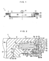
- a sliding bearing 1 of this embodiment includes an upper casing 3 having an annular lower surface 2; a lower casing 5 which is superposed on the upper casing 3 so as to be rotatable about an axis O of the upper casing 3 and has an annular upper surface 4 opposed to the annular lower surface 2 of the upper casing 3; an annular thrust sliding bearing piece 7 disposed in an annular space 6 between the annular lower surface 2 and the annular upper surface 4; a seal means 8 disposed on an outer peripheral side of the annular space 6; and a seal means 9 disposed on an inner peripheral side of the annular space 6.
- the upper casing 3 includes a circular ring-shaped upper annular plate portion 11 having the aforementioned annular lower surface 2; a hollow cylindrical, large-diameter upper outer cylindrical portion 14 formed integrally with a lower surface 13 (including the annular lower surface 2) on an outer peripheral surface 12 side of the upper annular plate portion 11; a circular ring-shaped annular enlarged portion 18 formed integrally with the portion of an inner peripheral surface 15 of a lower surface 16 side of the upper outer cylindrical portion 14; and a hollow cylindrical, small-diameter upper inner cylindrical portion 21 formed integrally with the lower surface 13 on an inner peripheral surface 19 side of the upper annular plate portion 11.
- the annular lower surface 2 is in contact with an annular upper surface 26 of the thrust sliding bearing piece 7 slidably in an R direction.
- the inner peripheral surface 15 of the upper outer cylindrical portion 14 has a portion whose diameter becomes larger with increasing distance from the upper annular plate portion 11.
- a portion 17 of the inner peripheral surface 15 from the upper annular plate portion 11 to the annular enlarged portion 18 is gradually enlarged in diameter from the upper annular plate portion 11 toward the annular enlarged portion 18.
- the annular enlarged portion 18 is formed in such a manner as to bulge from the outer side of the upper casing 3 toward the inner side thereof in the radial direction. Since the annular enlarged portion 18 is thus formed, the annular enlarged portion 18 has a portion which is gradually reduced in diameter from the upper annular plate portion 11 toward the lower side.
- the upper inner cylindrical portion 21 is inserted in a lower cylindrical portion 34 of the lower casing 5, and a shaft body constituted by a piston rod or the like is adapted to be inserted in a central hole 91 defined by the upper inner cylindrical portion 21.
- the lower casing 5 has a circular ring-shaped lower annular plate portion 31 having the annular upper surface 4, as well as the hollow cylindrical lower cylindrical portion 34 which is formed integrally with a lower surface 33 of an inner peripheral surface 32 side of the lower annular plate portion 31.
- the lower annular plate portion 31 includes a large-diameter annular plate portion 36, as well as a small-diameter annular plate portion 37 formed integrally with a lower surface 33a of the large-diameter annular plate portion 36.
- a circular ring-shaped annular indented portion 42 having a bottom surface serving as the annular upper surface 4 is formed on an upper surface 41 of the large-diameter annular plate portion 36.
- the thrust sliding bearing piece 7 is adapted to be disposed on the annular indented portion 42.
- the annular upper surface 4 is in contact with an annular lower surface 27 of the thrust sliding bearing piece 7 slidably in the R direction.
- An outer peripheral surface 43b of the small-diameter annular plate portion 37 and the lower surface 33a of the large-diameter annular plate portion 36 form in cooperation with each other an annular stepped portion 44 where a lower portion of an outer peripheral seal portion 61 is disposed on the lower surface 33 on an outer peripheral surface 43 side of the lower casing 5.
- An inner peripheral surface 51 of the lower cylindrical portion 34 is in contact with an outer peripheral surface 25 of the upper inner cylindrical portion 21 slidably in the R direction.
- the portion where the inner peripheral surface 51 of the lower cylindrical portion 34 and the outer peripheral surface 25 of the upper inner cylindrical portion 21 are thus in sliding contact with each other is formed as a radial bearing portion 50.
- a mating member formed by drawing e.g., a spring seat 53 on top of a coil spring in a strut-type suspension assembly, is adapted to abut against the lower surface 33 of the lower annular plate portion 31 and an outer peripheral surface 52 of the lower cylindrical portion 34.
- a grease sump groove 60 where grease such as silicone-based grease is disposed may be formed in the thrust sliding bearing piece 7, as shown in Fig. 2 .
- the thrust sliding bearing piece 7 is adapted to be brought into sliding contact with the annular lower surface 2 at its annular upper surface 26 and with the annular upper surface 4 at its annular lower surface 27.
- the thrust sliding bearing piece 7 may have two or more circular ring-shaped protrusions 28 which are formed integrally with the annular upper surface 26 and are brought into sliding contact with the annular lower surface 2, as well as two or more circular ring-shaped protrusions 38 which are formed integrally with the annular lower surface 27 and are brought into sliding contact with the annular upper surface 4.
- An annular sheet 59 which is brought into slidable contact with at least one of the thrust sliding bearing piece 7 and the upper casing 3 and/or the lower casing 5, may be interposed between the thrust sliding bearing piece 7 and the upper casing 3 and/or the lower casing 5, as shown in Fig. 7 .
- Such a sheet 59 has a thickness of, for instance, 0.05 mm to 1.0 mm, and is formed of a synthetic resin including at least one of polyamide resin, polyester resin, polyolefin resin, polycarbonate resin, and fluororesin.
- Grease may be filled in a closed recess 63 which is closed by the sheet 59 and the circular ring-shaped protrusions 28 and/or the circular ring-shaped protrusions 38.
- the upper casing 3, the lower casing 5, and the thrust sliding bearing piece 7 are preferably formed of synthetic resin, and the synthetic resin for forming the thrust sliding bearing piece 7 should preferably have self-lubricity, in particular, while the synthetic resin for forming upper casing 3 and the lower casing 5 should preferably excel in mechanical properties, such as wear resistance, shock resistance, creep resistance, and rigidity.
- the synthetic resin for forming the thrust sliding bearing piece 7 includes at least one of polyacetal resin, polyamide resin, polyester resin such as polybutylene terephthalate resin, polyolefin resin such as polyethylene resin and polypropylene resin, polycarbonate resin, and fluororesin.
- a synthetic resin similar to the synthetic resin for forming the thrust sliding bearing piece 7 can be used as the synthetic resin for forming the thrust sliding bearing piece 7 .
- a synthetic resin which exhibits a good frictional property in combination with the synthetic resin for forming the thrust sliding bearing piece 7 and which has relatively high rigidity is particularly preferable.
- a more preferable combination is that of polyethylene resin and polyacetal resin.
- the seal means 8 includes the outer peripheral seal portion 61 disposed between the upper casing 3 and the lower casing 5 in such a manner as to seal the outer peripheral side of the annular space 6, as well as an annular elastic projection 62 projecting downward toward the spring seat 53 abutting against the lower surface 33 of the lower casing 5.
- the outer peripheral seal portion 61 includes an annular core 71 which is fitted or secured to the lower annular plate portion 31 and has an L-shaped cross section, as well as an annular elastic seal member 75 which is secured to the core 71 so as to cover the core 71.
- the core 71 includes an elongated portion 76 which is fitted on an outer peripheral surface 43 a of the large-diameter annular plate portion 36 and is elongated in a vertical direction, as well as a short portion 77 which is disposed on the annular stepped portion 44, is fitted on the lower surface 33 on the outer peripheral surface 43 side of the lower casing 5, and extends in a horizontal direction.
- An outer peripheral surface 72 of the core 71, an upper end surface 73 continuing to an upper edge of the outer peripheral surface 72, and a lower end surface 74 continuing to a lower edge of the outer peripheral surface 72 are covered with an elastic seal member 75.
- the core 71 is fitted or secured to the lower annular plate portion 31.
- the elastic seal member 75 includes an annular body 86 secured to the core 71 so as to cover the core 71; a flexible outer thin-walled annular projecting edge portion 87 which is disposed on an outer peripheral side of the annular body 86, is formed integrally with an upper end, or in this embodiment a below-described portion 56, of that annular body 86, and is brought into sliding contact with the inner peripheral surface 15 of the upper outer cylindrical portion 14 so as to seal the outer peripheral side of the annular space 6; and a flexible inner thin-walled annular projecting edge portion 88 which is disposed on an inner peripheral side of the annular body 86, is formed integrally with a lower end, or in this embodiment a below-described portion 57, of that annular body 86, and is brought into sliding contact with the annular stepped portion 44 of the lower annular plate portion 31 so as to seal the outer peripheral side of the annular space 6.
- the elastic seal member 75 is formed of a material selected from a crosslinked rubber such as nitrile rubber, chloroprene rubber, fluoro rubber, urethane rubber, and silicone rubber, and a thermoplastic elastomer such as ester-based elastomer, olefin-based elastomer, urethane-based elastomer, and silicone-based elastomer.
- a crosslinked rubber such as nitrile rubber, chloroprene rubber, fluoro rubber, urethane rubber, and silicone rubber
- a thermoplastic elastomer such as ester-based elastomer, olefin-based elastomer, urethane-based elastomer, and silicone-based elastomer.
- the annular body 86 covers the outer peripheral surface 72, the upper end surface 73, and the lower end surface 74 of the core 71.
- a portion 55 of the annular body 86 covering the outer peripheral surface 72 of the core 71 is annular and has a substantially L-shaped cross section, and the portion 56 of the annular body 86 covering the upper end surface 73 of the core 71 and the portion 57 of the annular body 86 covering the lower end surface 74 of the core 71 are respectively annular.
- a lower surface 58 of the portion 55 of the annular body 86 is flush with the lower surface 33 in this embodiment.
- the outer thin-walled annular projecting edge portion 87 is inclined in such a manner as to be gradually removed away from the upper annular plate portion 11 as the outer thin-walled annular projecting edge portion 87 approaches the upper outer cylindrical portion 14.
- a maximum diameter of the outer thin-walled annular projecting edge portion 87 thus inclined is larger than or equal to the diameter of the inner peripheral surface 15 of the upper outer cylindrical portion 14 or, in this embodiment, larger than or equal to the maximum diameter of the inner peripheral surface 15.
- the outer thin-walled annular projecting edge portion 87 is interposed between the annular body 86 and the upper casing 3 in the radial direction.
- the inner thin-walled annular projecting edge portion 88 is inclined in such a manner as to be gradually removed away from the upper annular plate portion 11 as the inner thin-walled annular projecting edge portion 88 approaches the outer peripheral surface 43b of the small-diameter annular plate portion 37.
- a minimum diameter of the inner thin-walled annular projecting edge portion 88 thus inclined is smaller than or equal to the diameter of the outer peripheral surface 43b.
- the inner thin-walled annular projecting edge portion 88 is interposed between the small-diameter annular plate portion 37 and the annular body 86 in the radial direction.
- the elastic projection 62 includes a small-diameter annular projection 95 formed integrally with the lower surface 58 of the portion 55 of the annular body 86, as well as a large-diameter annular projection 96 formed integrally with the lower surface 58 of the annular body 86 and disposed on the more outer side than the annular projection 95. Respective projecting ends of the annular projections 95 and 96 are located lower than the lower surface 33 of the lower annular plate portion 31.
- the elastic projection 62 is formed of the same material as that of the elastic seal member 75.
- the annular projections 95 and 96 have mutually equal amounts of projection in this embodiment, and project downward by, for example, 0.1 mm or thereabouts from the lower surfaces 33 and 58.
- Each of the annular projections 95 and 96 has a circular arc-shaped cross section in this embodiment, but may have a triangular cross section, a rectangular cross section, or a trapezoidal cross section, for example. Since each of such annular projections 95 and 96 is formed integrally with the lower surface 58, each of the annular projections 95 and 96 is disposed on the more outer peripheral side than the small-diameter annular plate portion 37 abutting against the spring seat 53.
- each of the annular projections 95 and 96 prevents the entry of dust, rainwater, muddy water, or the like between the spring seat 53 and the lower annular plate portion 31, particularly into the more inner peripheral side of the lower annular plate portion 31 than the annular projections 95 and 96, and furthermore the entry of dust, rainwater, muddy water, or the like into the annular space 6 through the portion between, on the one hand, the annular stepped portion 44 and the large-diameter annular plate portion 36 and, on the other hand, the outer peripheral seal portion 61.
- annular projections 95 and 96 it is possible to maintain satisfactory sliding between the upper casing 3 and the thrust sliding bearing piece 7 and/or between the lower casing 5 and the thrust sliding bearing piece 7 over extended periods of time by suppressing the relative sliding between the spring seat 53 and the lower casing 5.
- the sliding bearing 1 in accordance with this embodiment has also the flexible inner thin-walled annular projecting edge portion 88 brought into sliding contact with the outer peripheral surface 43b of the small-diameter annular plate portion 37, and is hence adapted to prevent with higher sealability the above-described entry of dust, rainwater, muddy water, or the like.
- the annular projection 95 may project downward more than the annular projection 96, or the annular projection 96 may project downward more than the annular projection 95.
- the seal means 8 may have, in addition to the above-described configuration, a labyrinth structure 67 which has an annular recess 65 formed integrally with the lower annular plate portion 31 and recessed toward the upper annular plate portion 11, as well as an annular protrusion 66 formed integrally with the upper annular plate portion 11 and protruding toward the lower annular plate portion 31, and which is disposed between the outer peripheral seal portion 61 and the thrust sliding bearing piece 7 with respect to the radial direction.
- a labyrinth structure 67 which has an annular recess 65 formed integrally with the lower annular plate portion 31 and recessed toward the upper annular plate portion 11, as well as an annular protrusion 66 formed integrally with the upper annular plate portion 11 and protruding toward the lower annular plate portion 31, and which is disposed between the outer peripheral seal portion 61 and the thrust sliding bearing piece 7 with respect to the radial direction.
- the seal means 9 has an upwardly recessed annular recess 97 which is formed integrally with a lower end of the lower cylindrical portion 34 and a downwardly protruding annular protrusion 98 which is disposed in a space defined by the annular recess 97 and formed integrally with a lower end of the upper inner cylindrical portion 21.
- the seal means 9 has a labyrinth structure 99 which consists of such an annular recess 97 and an annular protrusion 98, and is adapted to seal the inner peripheral side of the annular space 6 between the upper casing 3 and the lower casing 5 by that labyrinth structure 99.
- seal means 9 in this embodiment has the labyrinth structure 99
- the seal means 9 may alternatively have, for instance, an elastic seal means (not shown) interposed between the lower end of the upper inner cylindrical portion 21 and the lower end of the lower cylindrical portion 34.
- the above-described sliding bearing 1 is used by being installed between, for example, on the one hand, the spring seat 53 which has been formed by drawing and is located on top of the coil spring in a strut-type suspension assembly and, on the other hand, a mounting member on the vehicle body side to which a piston rod of a hydraulic damper is secured.
- an upper portion of the piston rod is inserted in the central hole 91 of the sliding bearing 1 so as to be rotatable about the axis O in the R direction with respect to the upper casing 3 and the lower casing 5.
- the relative rotation of the spring seat 53 about the axis O in the R direction by means of the coil spring is effected by the relative rotation of the lower casing 5 in the same direction with respect to the upper casing 3.
- the strut-type suspension is disposed in that portion of the vehicle which is exposed to dust, rainwater, muddy water, or the like during the traveling of the vehicle, the working environment of the sliding bearing 1 incorporated in the strut-type suspension is extremely severe, so that it is important to improve the sealability of the sliding bearing 1.
- the sliding bearing 1 is comprised of the upper casing 3 having the annular lower surface 2; the lower casing 5 which is superposed on the upper casing 3 so as to be rotatable about the axis O in the R direction, and has the annular upper surface 4 opposed to the annular lower surface 2 of the upper casing 3; the annular thrust sliding bearing piece 7 disposed in the annular space 6 between the annular lower surface 2 and the annular upper surface 4; and the seal means 8 disposed on the outer peripheral side of the annular space 6.
- the seal means 8 includes the outer peripheral seal portion 61 disposed between the upper casing 3 and the lower casing 5 so as to seal the outer peripheral side of the annular space 6; and the annular elastic projection 62 formed on the lower surface 58 of the outer peripheral seal portion 61 and projecting toward the spring seat 53 formed by drawing and serving as the mating member abutting against the lower surface 33 of the lower casing 5. Therefore, even in a case where the fabrication accuracy of the spring seat 53 abutting against the lower casing 5 is low, by causing that elastic projection 62 to elastically abut against the spring seat 53, an unwanted gap, particularly a gap leading to between the lower casing 5 and the upper casing 3, is not produced between the lower casing 5 and the spring seat 53.
- the upper casing 3 includes the upper annular plate portion 11 having the annular lower surface 2 and the upper outer cylindrical portion 14 formed integrally with the lower surface 13 on the outer peripheral surface 12 side of the upper annular plate portion 11, while the lower casing 5 includes the lower annular plate portion 31 having the annular upper surface 4.
- the lower annular plate portion 31 has the large-diameter annular plate portion 36, as well as the small-diameter annular plate portion 37 formed integrally with the lower surface 33a of the large-diameter annular plate portion 36.
- the lower surface 33a of the large-diameter annular plate portion 36 and the outer peripheral surface 43b of the small-diameter annular plate portion 37 form in cooperation with each other the annular stepped portion 44 on the lower surface 33 on the outer peripheral surface 43 side of the lower casing 5.
- the outer peripheral seal portion 61 includes the annular core 71 which is fitted or secured to the lower annular plate portion 31 and has an L-shaped cross section, as well as the annular elastic seal member 75 which is secured to the core 71 so as to cover the core 71.
- the elastic seal member 75 includes the annular body 86 secured to the core 71 so as to cover the core 71; the flexible outer thin-walled annular projecting edge portion 87 which is disposed on the outer peripheral side of the annular body 86, is formed integrally with an upper end of that annular body 86, and is brought into sliding contact with the inner peripheral surface 15 of the upper outer cylindrical portion 14 so as to seal the outer peripheral side of the annular space 6; and the flexible inner thin-walled annular projecting edge portion 88 which is disposed on the inner peripheral side of the annular body 86, is formed integrally with a lower end of that annular body 86, and is brought into sliding contact with the annular stepped portion 44 so as to seal the outer peripheral side of the annular space 6.
- the elastic projection 62 makes it possible to prevent the entry of dust, rainwater, muddy water, or the like between the lower casing 5 and the spring seat 53 abutting against the lower surface 33 of this lower casing 5. Furthermore, the inner thin-walled annular projecting edge portion 88 makes it possible to prevent the entry of dust, rainwater, muddy water, or the like between the lower casing 5 and the upper casing 3. Hence, the entry of dust, rainwater, muddy water, or the like can be prevented with higher sealability.
- the outer thin-walled annular projecting edge portion 87 is inclined in such a manner as to be gradually removed away from the upper annular plate portion 11 as the outer thin-walled annular projecting edge portion 87 approaches the upper outer cylindrical portion 14. Further, the maximum diameter of the outer thin-walled annular projecting edge portion 87 is larger than or equal to the diameter of the inner peripheral surface 15 of the upper outer cylindrical portion 14. Therefore, it is possible to eliminate the possibility of the outer thin-walled annular projecting edge portion 87 being removed away from the upper outer cylindrical portion 14, thereby allowing high sealability to be exhibited.
- the inner thin-walled annular projecting edge portion 88 is inclined in such a manner as to be gradually removed away from the upper annular plate portion 11 as the inner thin-walled annular projecting edge portion 88 approaches the outer peripheral surface 43b of the small-diameter annular plate portion 37. Further, the minimum diameter of the inner thin-walled annular projecting edge portion 88 is smaller than or equal to the diameter of the outer peripheral surface 43b of the small-diameter annular plate portion 37. Therefore, high sealability can be exhibited by the inner thin-walled annular projecting edge portion 88 as well.
Landscapes
- Engineering & Computer Science (AREA)
- General Engineering & Computer Science (AREA)
- Mechanical Engineering (AREA)
- Sealing Of Bearings (AREA)
- Sliding-Contact Bearings (AREA)
Claims (8)
- Palier lisse comprenant :un carter supérieur (3) ayant une surface inférieure annulaire (2) ;un carter inférieur (5) qui est superposé sur ledit carter supérieur (3) de manière à pouvoir tourner autour d'un axe dudit carter supérieur (3) et qui comprend une partie de plaque annulaire inférieure (31) ayant une surface supérieure annulaire (4) opposée à la surface inférieure annulaire (2) dudit carter supérieur (3), la partie de plaque annulaire inférieure (31) comportant une partie de plaque annulaire de grand diamètre (36) et une partie de plaque annulaire de petit diamètre (37) formée d'un seul tenant avec une surface inférieure (33a) de la partie de plaque annulaire de grand diamètre (36),la surface inférieure (33a) de la partie de plaque annulaire de grand diamètre (36) et une surface périphérique extérieure (43b) de la partie de plaque annulaire de petit diamètre (37) formant en coopération l'une avec l'autre une partie étagée annulaire (44) sur une surface inférieure sur un côté de surface périphérique extérieure dudit carter inférieur (5) ;une pièce de palier lisse de butée annulaire (7) disposée dans un espace annulaire (6) entre la surface inférieure annulaire (2) et la surface supérieure annulaire (4) ; etun moyen d'étanchéité (8) placé sur un côté périphérique extérieur de l'espace annulaire (6),ledit moyen d'étanchéité (8) comprenant une partie d'étanchéité périphérique extérieure (61) disposée entre ledit carter supérieur (3) et ledit carter inférieur (5) afin de rendre étanche le côté périphérique extérieur de l'espace annulaire (6), ladite partie d'étanchéité périphérique extérieure (61) comprenant un élément d'étanchéité élastique annulaire (75) ayant un corps annulaire (86), et un noyau annulaire (71) qui est assemblé ou fixé sur la partie de plaque annulaire inférieure (31) et qui est de section transversale en forme de L, ledit élément d'étanchéité élastique annulaire (75) étant fixé au noyau (71) de manière à couvrir le noyau (71),ladite partie d'étanchéité périphérique extérieure (61) comprend en outre une partie de bord saillante annulaire à paroi mince intérieure flexible (88) qui est disposée sur un côté périphérique intérieur du corps annulaire (86) qui est incliné et formé d'un seul tenant avec une extrémité inférieure du corps annulaire (86),ladite partie de bord saillante annulaire à paroi mince intérieure flexible (88) est fléchie et mise en contact avec une surface périphérique extérieure (43b) de ladite partie de plaque annulaire de petit diamètre (37) au niveau d'un surface périphérique intérieure inclinée de celle-ci sur la partie étagée annulaire (44) afin de rendre étanche le côté périphérique extérieur de l'espace annulaire (6),caractérisé en ce que :ledit moyen d'étanchéité (8) comprend en outre une protubérance élastique annulaire (62) formée sur une surface inférieure (58) de la partie d'étanchéité périphérique extérieure (61) et fait saillie vers un élément conjugué qui peut buter contre une surface inférieure (33) dudit carter inférieur (5),ladite protubérance élastique (62) comprend une protubérance annulaire de petit diamètre (95) formée d'un seul tenant sur la surface inférieure (58) de la partie d'étanchéité périphérique extérieure (61) et une protubérance annulaire de grand diamètre (96) formée d'un seul tenant sur la surface inférieure (58) de la partie d'étanchéité périphérique extérieure (61) et placée sur un côté plus extérieur que la protubérance annulaire de petit diamètre (95), etchacune des protubérance annulaire de petit diamètre (95) et protubérance annulaire de grand diamètre (96) est placée sur un côté périphérique plus extérieur que la partie de plaque annulaire de petit diamètre (37).
- Palier lisse selon la revendication 1, dans lequel ledit carter supérieur (3) comprend une partie de plaque annulaire supérieure (11) comportant la surface inférieure annulaire (2) et une partie cylindrique extérieure supérieure (14) formée d'un seul tenant avec une surface inférieure (2, 13) sur un côté de surface périphérique extérieure de la partie de plaque annulaire supérieure (11), l'élément d'étanchéité élastique (75) comprenant en outre une partie de bord saillante annulaire à paroi mince extérieure flexible (87) qui est disposée sur un côté périphérique extérieur du corps annulaire (86), qui est formée d'un seul tenant avec une extrémité supérieure (56) du corps annulaire (86), et qui est mise en contact glissant avec une surface périphérique intérieure (15) de la partie cylindrique extérieure supérieure (14) afin de rendre étanche le côté périphérique extérieur de l'espace annulaire (6), ledit corps annulaire (86) étant fixé au noyau (71) de manière à couvrir le noyau (71).
- Palier lisse selon la revendication 2, dans lequel la partie de bord saillante annulaire à paroi mince extérieure (87) est inclinée de manière à être écartée progressivement de la partie de plaque annulaire supérieure (11) à mesure que la partie de bord saillante annulaire à paroi mince extérieure (87) s'approche de la partie cylindrique extérieure supérieure (14), et un diamètre maximum de la partie de bord saillante annulaire à paroi mince extérieure (87) est supérieur ou égal à un diamètre de la surface périphérique intérieure (15) de la partie cylindrique extérieure supérieure (14).
- Palier lisse selon l'une quelconque des revendications 1 à 3, dans lequel la partie de bord saillante annulaire à paroi mince intérieure (88) est inclinée de manière à être écartée progressivement de la partie de plaque annulaire supérieure (11) à mesure que la partie de bord saillante annulaire à paroi mince intérieure (88) s'approche de la surface périphérique extérieure (43b) de la partie de plaque annulaire de petit diamètre (37), et un diamètre minimum de la partie de bord saillante annulaire à paroi mince intérieure (88) est inférieur ou égal à un diamètre de la surface périphérique extérieure (43b) de la partie de plaque annulaire de petit diamètre (37).
- Palier lisse selon l'une quelconque des revendications 1 à 4, dans lequel la partie d'étanchéité périphérique extérieure (61) et la protubérance élastique (62) sont faites d'un caoutchouc réticulé ou d'un élastomère thermoplastique.
- Palier lisse selon l'une quelconque des revendications 1 à 5, dans lequel au moins l'un desdits carter supérieur (3) et carter inférieur (5) est fait d'une résine synthétique, et la résine synthétique servant à former au moins l'un desdits carter supérieur (3) et carter inférieur (5) comprend au moins une résine parmi une résine polyacétal, une résine polyamide, une résine polyester, une résine polyoléfinique, une résine polycarbonate et une résine fluorée.
- Palier lisse selon l'une quelconque des revendications 1 à 6, dans lequel ladite pièce de palier lisse de butée (7) est faite d'une résine synthétique, et la résine synthétique servant à former ladite pièce de palier lisse de butée (7) comprend au moins une résine parmi une résine polyacétal, une résine polyamide, une résine polyester, une résine polyoléfinique, une résine polycarbonate et une résine fluorée.
- Palier lisse selon l'une quelconque des revendications 1 à 7, comprenant en outre un moyen d'étanchéité (9) placé sur un côté périphérique intérieur de l'espace annulaire (6).
Applications Claiming Priority (2)
| Application Number | Priority Date | Filing Date | Title |
|---|---|---|---|
| JP2006134544A JP5561660B2 (ja) | 2006-05-12 | 2006-05-12 | 滑り軸受 |
| EP07737156A EP2022994B1 (fr) | 2006-05-12 | 2007-05-10 | Palier lisse |
Related Parent Applications (2)
| Application Number | Title | Priority Date | Filing Date |
|---|---|---|---|
| EP07737156A Division EP2022994B1 (fr) | 2006-05-12 | 2007-05-10 | Palier lisse |
| EP07737156.5 Division | 2007-05-10 |
Publications (2)
| Publication Number | Publication Date |
|---|---|
| EP2428693A1 EP2428693A1 (fr) | 2012-03-14 |
| EP2428693B1 true EP2428693B1 (fr) | 2014-02-26 |
Family
ID=38693657
Family Applications (2)
| Application Number | Title | Priority Date | Filing Date |
|---|---|---|---|
| EP07737156A Active EP2022994B1 (fr) | 2006-05-12 | 2007-05-10 | Palier lisse |
| EP11192658.0A Active EP2428693B1 (fr) | 2006-05-12 | 2007-05-10 | Palier lisse |
Family Applications Before (1)
| Application Number | Title | Priority Date | Filing Date |
|---|---|---|---|
| EP07737156A Active EP2022994B1 (fr) | 2006-05-12 | 2007-05-10 | Palier lisse |
Country Status (8)
| Country | Link |
|---|---|
| US (1) | US9194435B2 (fr) |
| EP (2) | EP2022994B1 (fr) |
| JP (1) | JP5561660B2 (fr) |
| KR (3) | KR20090021164A (fr) |
| CN (1) | CN101438069B (fr) |
| BR (1) | BRPI0712240B1 (fr) |
| RU (1) | RU2427732C2 (fr) |
| WO (1) | WO2007132556A1 (fr) |
Families Citing this family (30)
| Publication number | Priority date | Publication date | Assignee | Title |
|---|---|---|---|---|
| JP4997822B2 (ja) * | 2006-05-15 | 2012-08-08 | オイレス工業株式会社 | 滑り軸受 |
| JP5233370B2 (ja) * | 2008-04-02 | 2013-07-10 | オイレス工業株式会社 | スラスト滑り軸受 |
| JP5332379B2 (ja) | 2008-07-28 | 2013-11-06 | オイレス工業株式会社 | 合成樹脂製スラスト滑り軸受 |
| JP5704625B2 (ja) * | 2009-12-11 | 2015-04-22 | オイレス工業株式会社 | 合成樹脂製スラスト滑り軸受 |
| JP5365557B2 (ja) * | 2010-03-17 | 2013-12-11 | オイレス工業株式会社 | スラスト滑り軸受及びこのスラスト滑り軸受とピストンロッドとの組合せ機構 |
| JP5673110B2 (ja) | 2011-01-07 | 2015-02-18 | オイレス工業株式会社 | スラスト滑り軸受及びこのスラスト滑り軸受を用いたストラット型サスペンションの取付構造 |
| JP5786356B2 (ja) * | 2011-02-18 | 2015-09-30 | 日本精工株式会社 | 直動案内装置 |
| WO2012145610A1 (fr) * | 2011-04-21 | 2012-10-26 | Illinois Tool Works Inc. | Étanchéité pour palier de butée |
| JP5906590B2 (ja) * | 2011-06-09 | 2016-04-20 | オイレス工業株式会社 | 合成樹脂製の滑り軸受 |
| JP5842402B2 (ja) | 2011-06-20 | 2016-01-13 | オイレス工業株式会社 | スラスト滑り軸受 |
| JP5909976B2 (ja) * | 2011-10-07 | 2016-04-27 | オイレス工業株式会社 | 合成樹脂製の滑り軸受 |
| JP5910000B2 (ja) * | 2011-11-02 | 2016-04-27 | オイレス工業株式会社 | 合成樹脂製の滑り軸受 |
| JP2013148132A (ja) * | 2012-01-17 | 2013-08-01 | Oiles Corp | スラスト滑り軸受 |
| JP6064438B2 (ja) * | 2012-08-22 | 2017-01-25 | オイレス工業株式会社 | 合成樹脂製のスラスト滑り軸受 |
| JP6194586B2 (ja) * | 2013-01-29 | 2017-09-13 | オイレス工業株式会社 | 合成樹脂製の滑り軸受 |
| JP5765413B2 (ja) * | 2013-12-20 | 2015-08-19 | オイレス工業株式会社 | 合成樹脂製のスラスト滑り軸受 |
| JP2015215032A (ja) * | 2014-05-09 | 2015-12-03 | オイレス工業株式会社 | スラスト滑り軸受 |
| CN104329379B (zh) * | 2014-10-11 | 2018-04-03 | 增城市祐大轴承五金制造有限公司 | 一种防尘污轴承 |
| JP6602042B2 (ja) | 2015-04-28 | 2019-11-06 | オイレス工業株式会社 | 滑り軸受 |
| JP2017089666A (ja) | 2015-11-02 | 2017-05-25 | オイレス工業株式会社 | 合成樹脂製滑り軸受 |
| WO2017094686A1 (fr) * | 2015-12-02 | 2017-06-08 | オイレス工業株式会社 | Palier de coulissement en résine synthétique |
| JP2017125598A (ja) * | 2016-01-15 | 2017-07-20 | オイレス工業株式会社 | 滑り軸受 |
| US10718375B2 (en) * | 2016-05-16 | 2020-07-21 | Roller Bearing Company Of America, Inc. | Bearing system with self-lubrication features, seals, grooves and slots for maintenance-free operation |
| CN106216407B (zh) * | 2016-07-26 | 2018-06-19 | 天津天重中直科技工程有限公司 | 短应力线轧机辊系装配中作用面增大的支撑块结构 |
| JP6917290B2 (ja) * | 2017-12-12 | 2021-08-11 | オイレス工業株式会社 | 滑り軸受 |
| JP7128002B2 (ja) * | 2018-03-22 | 2022-08-30 | オイレス工業株式会社 | 滑り軸受およびその製造方法 |
| EP3906367B1 (fr) | 2018-12-31 | 2024-04-10 | Saint-Gobain Performance Plastics Pampus GmbH | Palier de butée et son procédé de fabrication et d'utilisation |
| DE102020200586A1 (de) * | 2020-01-20 | 2021-07-22 | Aktiebolaget Skf | Aufhängungsaxiallagervorrichtung |
| KR102745134B1 (ko) * | 2020-06-03 | 2024-12-23 | 현대모비스 주식회사 | 차량용 회전유도장치 |
| CN114738383A (zh) * | 2021-01-07 | 2022-07-12 | 易格斯(上海)拖链系统有限公司 | 塑料滑动轴承 |
Family Cites Families (16)
| Publication number | Priority date | Publication date | Assignee | Title |
|---|---|---|---|---|
| JPS468485Y1 (fr) * | 1966-04-20 | 1971-03-25 | ||
| US3844631A (en) * | 1973-06-25 | 1974-10-29 | Timken Co | Unitized thrust bearing and interlocking seal assembly therefor |
| US4969752A (en) * | 1986-09-01 | 1990-11-13 | Oiles Industry Co., Ltd. | Thrust bearing made of synthetic resin |
| JPH068485Y2 (ja) | 1987-09-22 | 1994-03-02 | 横河電機株式会社 | 二次元位置検出装置 |
| DE3809703C2 (de) * | 1988-03-23 | 1996-08-08 | Schaeffler Waelzlager Kg | Axialgleitlager |
| US4925323A (en) * | 1989-08-23 | 1990-05-15 | General Motors Corporation | Unitized sealed thrust bearing assembly |
| JP2554722Y2 (ja) * | 1992-03-30 | 1997-11-17 | 光洋精工株式会社 | 密封形スラスト玉軸受 |
| JP3671459B2 (ja) | 1995-06-02 | 2005-07-13 | オイレス工業株式会社 | 合成樹脂スラスト軸受 |
| DE29600704U1 (de) * | 1996-01-17 | 1996-03-07 | Skf Gmbh, 97421 Schweinfurt | Axialwälzlager, insbesondere für eine Achsschenkellagerung |
| JP4482961B2 (ja) * | 1999-07-15 | 2010-06-16 | オイレス工業株式会社 | 合成樹脂製の滑り軸受 |
| JP4419217B2 (ja) * | 1999-07-15 | 2010-02-24 | オイレス工業株式会社 | 合成樹脂製の滑り軸受 |
| JP3988397B2 (ja) * | 2001-02-27 | 2007-10-10 | オイレス工業株式会社 | 合成樹脂製の滑り軸受 |
| RU20879U1 (ru) * | 2001-06-19 | 2001-12-10 | Калинин Сергей Николаевич | Верхняя опора направляющей пружинной стойки подвески автомобиля |
| CA2358947A1 (fr) * | 2001-10-12 | 2003-04-12 | Bayer Inc. | Reticulation de caoutchouc nitrile carboxyle, hydrogenation du caoutchouc nitrile carboxyle, le caoutchouc reticule et ses applications |
| JP4288930B2 (ja) * | 2002-10-03 | 2009-07-01 | オイレス工業株式会社 | 滑り軸受 |
| JP4380177B2 (ja) * | 2003-02-28 | 2009-12-09 | オイレス工業株式会社 | スラスト滑り軸受 |
-
2006
- 2006-05-12 JP JP2006134544A patent/JP5561660B2/ja active Active
-
2007
- 2007-05-10 KR KR1020087030251A patent/KR20090021164A/ko not_active Ceased
- 2007-05-10 KR KR1020147026733A patent/KR20140127358A/ko not_active Ceased
- 2007-05-10 RU RU2008147811/11A patent/RU2427732C2/ru not_active IP Right Cessation
- 2007-05-10 EP EP07737156A patent/EP2022994B1/fr active Active
- 2007-05-10 BR BRPI0712240-3A patent/BRPI0712240B1/pt active IP Right Grant
- 2007-05-10 WO PCT/JP2007/000500 patent/WO2007132556A1/fr not_active Ceased
- 2007-05-10 KR KR1020137031804A patent/KR20130140223A/ko not_active Ceased
- 2007-05-10 CN CN200780016739XA patent/CN101438069B/zh active Active
- 2007-05-10 US US12/299,685 patent/US9194435B2/en active Active
- 2007-05-10 EP EP11192658.0A patent/EP2428693B1/fr active Active
Also Published As
| Publication number | Publication date |
|---|---|
| KR20140127358A (ko) | 2014-11-03 |
| EP2022994A1 (fr) | 2009-02-11 |
| CN101438069A (zh) | 2009-05-20 |
| EP2022994B1 (fr) | 2012-03-21 |
| BRPI0712240B1 (pt) | 2020-03-17 |
| WO2007132556A1 (fr) | 2007-11-22 |
| BRPI0712240A2 (pt) | 2012-01-10 |
| KR20090021164A (ko) | 2009-02-27 |
| EP2428693A1 (fr) | 2012-03-14 |
| US20090180719A1 (en) | 2009-07-16 |
| JP5561660B2 (ja) | 2014-07-30 |
| CN101438069B (zh) | 2011-02-23 |
| US9194435B2 (en) | 2015-11-24 |
| RU2427732C2 (ru) | 2011-08-27 |
| JP2007303613A (ja) | 2007-11-22 |
| RU2008147811A (ru) | 2010-06-20 |
| KR20130140223A (ko) | 2013-12-23 |
| EP2022994A4 (fr) | 2009-11-11 |
Similar Documents
| Publication | Publication Date | Title |
|---|---|---|
| EP2428693B1 (fr) | Palier lisse | |
| US8016489B2 (en) | Sliding bearing | |
| EP1365162B1 (fr) | Coussinet coulissant en resine synthetique | |
| EP2679843A1 (fr) | Palier de butée lisse en résine synthétique | |
| KR102361216B1 (ko) | 미끄럼 베어링 | |
| JP4482961B2 (ja) | 合成樹脂製の滑り軸受 | |
| EP2765320A1 (fr) | Palier lisse en résine synthétique | |
| EP3683463B1 (fr) | Palier lisse | |
| JP5234197B2 (ja) | 滑り軸受 | |
| JP4380177B2 (ja) | スラスト滑り軸受 | |
| EP3530970A1 (fr) | Palier lisse | |
| EP3385555A1 (fr) | Palier de coulissement en résine synthétique | |
| JP2020063839A (ja) | 直動軸受用止め輪及び直動軸受 |
Legal Events
| Date | Code | Title | Description |
|---|---|---|---|
| AC | Divisional application: reference to earlier application |
Ref document number: 2022994 Country of ref document: EP Kind code of ref document: P |
|
| AK | Designated contracting states |
Kind code of ref document: A1 Designated state(s): DE FR |
|
| PUAI | Public reference made under article 153(3) epc to a published international application that has entered the european phase |
Free format text: ORIGINAL CODE: 0009012 |
|
| 17P | Request for examination filed |
Effective date: 20120914 |
|
| 17Q | First examination report despatched |
Effective date: 20121019 |
|
| GRAP | Despatch of communication of intention to grant a patent |
Free format text: ORIGINAL CODE: EPIDOSNIGR1 |
|
| INTG | Intention to grant announced |
Effective date: 20130924 |
|
| RAP1 | Party data changed (applicant data changed or rights of an application transferred) |
Owner name: OILES CORPORATION |
|
| RAP1 | Party data changed (applicant data changed or rights of an application transferred) |
Owner name: OILES CORPORATION |
|
| GRAS | Grant fee paid |
Free format text: ORIGINAL CODE: EPIDOSNIGR3 |
|
| GRAA | (expected) grant |
Free format text: ORIGINAL CODE: 0009210 |
|
| AC | Divisional application: reference to earlier application |
Ref document number: 2022994 Country of ref document: EP Kind code of ref document: P |
|
| AK | Designated contracting states |
Kind code of ref document: B1 Designated state(s): DE FR |
|
| REG | Reference to a national code |
Ref country code: DE Ref legal event code: R096 Ref document number: 602007035302 Country of ref document: DE Effective date: 20140410 |
|
| REG | Reference to a national code |
Ref country code: DE Ref legal event code: R097 Ref document number: 602007035302 Country of ref document: DE |
|
| PLBE | No opposition filed within time limit |
Free format text: ORIGINAL CODE: 0009261 |
|
| STAA | Information on the status of an ep patent application or granted ep patent |
Free format text: STATUS: NO OPPOSITION FILED WITHIN TIME LIMIT |
|
| 26N | No opposition filed |
Effective date: 20141127 |
|
| REG | Reference to a national code |
Ref country code: DE Ref legal event code: R097 Ref document number: 602007035302 Country of ref document: DE Effective date: 20141127 |
|
| REG | Reference to a national code |
Ref country code: FR Ref legal event code: PLFP Year of fee payment: 10 |
|
| REG | Reference to a national code |
Ref country code: FR Ref legal event code: PLFP Year of fee payment: 11 |
|
| REG | Reference to a national code |
Ref country code: FR Ref legal event code: PLFP Year of fee payment: 12 |
|
| REG | Reference to a national code |
Ref country code: FR Ref legal event code: PLFP Year of fee payment: 17 |
|
| REG | Reference to a national code |
Ref country code: DE Ref legal event code: R081 Ref document number: 602007035302 Country of ref document: DE Owner name: OILES CORPORATION, FUJISAWA-SHI, JP Free format text: FORMER OWNER: OILES CORP., TOKIO/TOKYO, JP |
|
| PGFP | Annual fee paid to national office [announced via postgrant information from national office to epo] |
Ref country code: DE Payment date: 20250402 Year of fee payment: 19 |
|
| PGFP | Annual fee paid to national office [announced via postgrant information from national office to epo] |
Ref country code: FR Payment date: 20250401 Year of fee payment: 19 |