EP2428745A2 - Elektrischer Heizblock und Durchlauferhitzer - Google Patents
Elektrischer Heizblock und Durchlauferhitzer Download PDFInfo
- Publication number
- EP2428745A2 EP2428745A2 EP11172648A EP11172648A EP2428745A2 EP 2428745 A2 EP2428745 A2 EP 2428745A2 EP 11172648 A EP11172648 A EP 11172648A EP 11172648 A EP11172648 A EP 11172648A EP 2428745 A2 EP2428745 A2 EP 2428745A2
- Authority
- EP
- European Patent Office
- Prior art keywords
- flow
- heating block
- heating
- limiting unit
- housing
- Prior art date
- Legal status (The legal status is an assumption and is not a legal conclusion. Google has not performed a legal analysis and makes no representation as to the accuracy of the status listed.)
- Granted
Links
- 238000010438 heat treatment Methods 0.000 title claims abstract description 54
- XLYOFNOQVPJJNP-UHFFFAOYSA-N water Substances O XLYOFNOQVPJJNP-UHFFFAOYSA-N 0.000 title claims description 29
- 239000012530 fluid Substances 0.000 claims abstract description 11
- 238000005485 electric heating Methods 0.000 claims description 8
- 238000011144 upstream manufacturing Methods 0.000 claims description 6
- 230000010354 integration Effects 0.000 description 4
- 238000007789 sealing Methods 0.000 description 4
- 239000000243 solution Substances 0.000 description 3
- 238000011109 contamination Methods 0.000 description 2
- 238000006073 displacement reaction Methods 0.000 description 2
- 238000005516 engineering process Methods 0.000 description 2
- 238000009434 installation Methods 0.000 description 2
- 230000000712 assembly Effects 0.000 description 1
- 238000000429 assembly Methods 0.000 description 1
- 238000004891 communication Methods 0.000 description 1
- 230000003247 decreasing effect Effects 0.000 description 1
- 230000001419 dependent effect Effects 0.000 description 1
- 238000011161 development Methods 0.000 description 1
- 230000018109 developmental process Effects 0.000 description 1
- 239000008236 heating water Substances 0.000 description 1
- 238000001746 injection moulding Methods 0.000 description 1
- 238000012423 maintenance Methods 0.000 description 1
- 238000004023 plastic welding Methods 0.000 description 1
Images
Classifications
-
- F—MECHANICAL ENGINEERING; LIGHTING; HEATING; WEAPONS; BLASTING
- F24—HEATING; RANGES; VENTILATING
- F24H—FLUID HEATERS, e.g. WATER OR AIR HEATERS, HAVING HEAT-GENERATING MEANS, e.g. HEAT PUMPS, IN GENERAL
- F24H1/00—Water heaters, e.g. boilers, continuous-flow heaters or water-storage heaters
- F24H1/10—Continuous-flow heaters, i.e. heaters in which heat is generated only while the water is flowing, e.g. with direct contact of the water with the heating medium
- F24H1/12—Continuous-flow heaters, i.e. heaters in which heat is generated only while the water is flowing, e.g. with direct contact of the water with the heating medium in which the water is kept separate from the heating medium
- F24H1/14—Continuous-flow heaters, i.e. heaters in which heat is generated only while the water is flowing, e.g. with direct contact of the water with the heating medium in which the water is kept separate from the heating medium by tubes, e.g. bent in serpentine form
- F24H1/142—Continuous-flow heaters, i.e. heaters in which heat is generated only while the water is flowing, e.g. with direct contact of the water with the heating medium in which the water is kept separate from the heating medium by tubes, e.g. bent in serpentine form using electric energy supply
-
- F—MECHANICAL ENGINEERING; LIGHTING; HEATING; WEAPONS; BLASTING
- F24—HEATING; RANGES; VENTILATING
- F24H—FLUID HEATERS, e.g. WATER OR AIR HEATERS, HAVING HEAT-GENERATING MEANS, e.g. HEAT PUMPS, IN GENERAL
- F24H9/00—Details
- F24H9/20—Arrangement or mounting of control or safety devices
- F24H9/2007—Arrangement or mounting of control or safety devices for water heaters
- F24H9/2014—Arrangement or mounting of control or safety devices for water heaters using electrical energy supply
- F24H9/2028—Continuous-flow heaters
Definitions
- the present invention relates to an electric heating block, in particular for a water heater, according to the preamble of claim 1, wherein the heating block is a housing in which a flow channel for defining a heating path for a fluid is formed and in the heating elements for heating the flowing through the flow channel Fluid can be arranged, and a flow-limiting unit for adjusting a flow cross-section has, and a water heater with such a heating block.
- the heating block is a housing in which a flow channel for defining a heating path for a fluid is formed and in the heating elements for heating the flowing through the flow channel Fluid can be arranged, and a flow-limiting unit for adjusting a flow cross-section has, and a water heater with such a heating block.
- Modern electrically controlled instantaneous water heaters are able to regulate an outlet temperature to the power limit to the degree.
- the unit output is often insufficient to reach the set target temperature.
- so-called fully electronically controlled instantaneous water heaters have been developed, which additionally have an electronically controlled flow limitation unit, with the help of which the electronic control adjusts the flow dynamically, so that the set target temperature is reached even if the user for the required temperature too high Water flow has chosen.
- Previous flow limitation units are independent assemblies that are subsequently connected to the internal water supply of the heating block. The connection often takes place via sleeve or threaded inserts, which represent in addition to an increased assembly costs and higher costs, in particular potential leaks.
- the object of the invention is to provide an electric heating block, in particular for a water heater, which eliminates the aforementioned disadvantages and allows a simple, space-saving and cost-effective positioning of a flow-limiting unit, and to provide a water heater with such a heating block.
- An inventive electric heating block for a water heater has a housing in which a flow channel for defining a heating path for a fluid is formed and in the heating elements for heating the fluid flowing through the flow channel can be arranged.
- the heating block has a flow-limiting unit for setting a flow cross-section, which is inventively integrated into the housing and at least partially immersed with a valve body in the flow channel.
- the integration of the flow-limiting unit according to the invention into the heating block Due to the integration of the flow-limiting unit according to the invention into the heating block, subsequent installation thereof is eliminated, so that the installation effort of the heating block in a water heater is reduced compared to known solutions. In addition, no potential weak points such as leaks between the heating block and the flow-limiting unit are formed by the integration, so that the heating block according to the invention is very robust.
- the flow-limiting unit virtually does not need its own housing and is thus compact enough to carry out that even small-flow water heaters, in which the space is usually very cramped, can be factory-equipped with the integral flow-limiting unit according to the invention. In addition, during commissioning by the craftsman or the end customer, no accessories that are absolutely necessary for operation must be installed.
- the housing of the heating block can be made of plastic.
- the flow restriction unit is integral with the housing of the heating block. ie integrated, executed. This means that at least part of the flow restriction unit is integral with the heater block housing. This can be realized for example in an injection molding process, wherein a plastic welding is also used. Therefore, a flow restriction unit made as it were in one piece with the heating block can be provided.
- the flow restriction unit is inserted into an opening of the housing and positioned in the region of a flow section of the flow channel.
- the valve body is a valve spool which cooperates with a wall portion of the flow area formed as a valve seat.
- a valve spool can be relatively easily integrated into the housing or the flow area, so that such a solution is particularly inexpensive.
- the valve seat is integrally formed integrally with the housing, in particular plastic housing, of the heating block. That the housing of the heating block simultaneously serves as the housing of the flow-limiting unit, in which the valve seat is designed directly in an opening of the heating block or of the heating block housing.
- this head side may have a preferably finger-like or lance-like projection, which dives in sections in a recess introduced into the valve seat.
- valve spool The adjustment of the valve spool can be done via an electric motor actuator.
- actuators are relatively robust, small and inexpensive.
- the valve spool may include a rack-like body portion which is operatively connected to a pinion of the actuator.
- a gear engagement is very sensitive adjustable, so that the flow cross-section can be set extremely sensitive.
- relatively few moving components for controlling the valve spool are needed.
- the flow channel preferably has a reduced flow cross-section compared to adjacent flow sections. As a result, even the smallest adjustment or travel paths of the valve slide are sufficient to change the flow.
- a strainer is installed in the flow area upstream of the flow-limiting unit or of the valve spool.
- a preferred electric instantaneous water heater is equipped with a heating block according to the invention.
- Such a flow heater is particularly compact, robust, easy to install and inexpensive.
- the present invention is particularly suitable for providing an electric heating block for a water heater in the field of home appliance technology, which is compact, robust, easy to install and inexpensive.
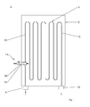
- FIG. 1 shows a simplified longitudinal section through an electric heating block 1 according to the invention for a water heater for heating water.
- This has a housing 2, in which a meandering flow channel 4 is designed to define a heating section.
- the heating block 1 is designed in bare-wire technology with a plurality of not shown in the flow channel 4 heating elements for heating the water.
- the housing 2 For supplying water to be heated and for removing the heated water, the housing 2 has an inlet connection 6 and an outlet connection 8, which are in fluid communication with a heating element-free flow region 10 or a heating element-free trailing region 12 of the flow channel 4.
- a flow-limiting unit 14 is integrated into the housing 2, the valve slide 18 of which is guided through an opening 16 in the housing 2 into the flow area 10.
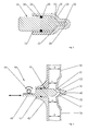
- the valve spool 18 has according to FIG. 2 an extending in the direction of adjustment cylindrical shape with a hemispherical slider head 20 which cooperates with a shell-like valve seat 22 which is formed by a relative to the opening 16 positioned wall portion 24 of the flow area or flow channel 10.
- the valve spool 18 is guided longitudinally in the opening 16, which is sealed by a sealing ring 26 which is inserted into a circumferential groove 28 of the valve spool 18 and in abutment with an inner wall portion 30 of the opening 16.
- valve slide 18 In order to prevent the valve slide 18 from being tilted in the opening 16 when there is an axial displacement or that the sealing ring 26 is damaged, the valve slide 18 has a finger 32 on the head side, which dives in sections into a recess 34 formed in the valve seat 22.
- the wall section 24 is offset radially in the direction of the opening 16 in the region of the flow-limiting unit 14 so that the flow channel 10 immediately upstream and downstream of the valve seat 22 has a flow cross-section A R which reduces compared to the flow cross-section A of adjacent upstream and downstream channel sections 36, 38 is.
- the recess 34 is formed in this embodiment in a radially outwardly directed projection 40 of the flow channel 10.
- the opening 16 is formed in a radially outwardly directed projection 42, whereby on the one hand is achieved that the valve spool 18 can completely open the flow channel.
- the flow channel 10 has a constant wall thickness substantially over its entire length.
- the flow-limiting unit 14 has an electromechanical actuator 44.
- This has a pinion 46 which is mounted on a drive shaft of a servo motor, not shown, for example, a stepper motor, and with a foot-side extending in the longitudinal direction tooth-like body portion 48 of the valve spool 18 is in operative engagement.
- a servo motor not shown, for example, a stepper motor
- a sieve is arranged upstream of the flow-limiting unit 14 or integrated therein.
- the actuator 44 When switching on the water heater, the actuator 44 is driven in response to a set temperature by the operator that the valve spool 18 is moved by a rotation of the pinion 46 so that the flow area in the region of the valve seat 22 is increased or decreased. As shown in FIG. 3 An enlargement of the flow cross-section means a movement of the valve spool 18 to the left and thus a movement away from the valve seat 22.
- An increase in the flow cross-section accordingly means a movement of the valve spool 18 to the right and thus a movement in the direction of the valve seat 22nd
- an electric heating block for a water heater comprising a housing in which a flow channel is formed for defining a heating path for a fluid and in the heating elements for heating the fluid flowing through the flow channel can be arranged, as well as with a flow-limiting unit for adjusting a flow cross-section, wherein the flow-limiting unit is integrated in the housing and with a valve body at least partially immersed in the flow channel
Landscapes
- Engineering & Computer Science (AREA)
- Physics & Mathematics (AREA)
- Thermal Sciences (AREA)
- Chemical & Material Sciences (AREA)
- Combustion & Propulsion (AREA)
- Mechanical Engineering (AREA)
- General Engineering & Computer Science (AREA)
- Multiple-Way Valves (AREA)
- Details Of Valves (AREA)
- Instantaneous Water Boilers, Portable Hot-Water Supply Apparatuses, And Control Of Portable Hot-Water Supply Apparatuses (AREA)
- Temperature-Responsive Valves (AREA)
Abstract
Description
- Die vorliegende Erfindung betrifft einen elektrischen Heizblock, insbesondere für einen Durchlauferhitzer, nach dem Oberbegriff des Patentanspruchs 1, wobei der Heizblock ein Gehäuse, in dem ein Strömungskanal zur Definierung einer Heizstrecke für ein Fluid ausgebildet ist und in dem Heizelemente zum Erhitzen des durch den Strömungskanal strömenden Fluids anordbar sind, und eine Durchflussbegrenzungseinheit zum Einstellen eines Durchflussquerschnitts hat, sowie einen Durchlauferhitzer mit einem derartigen Heizblock.
- Moderne elektrisch geregelte Durchlauferhitzer sind in der Lage, eine Auslauftemperatur bis zur Leistungsgrenze gradgenau zu regeln. Bei geringeren Zulauftemperaturen, hohen Solltemperaturen und einem zu hohen Wasserdurchfluss reicht die Geräteleistung häufig jedoch nicht mehr aus, um die eingestellte Solltemperatur zu erreichen. Aus diesem Grund wurden sogenannte vollelektronisch geregelte Durchlauferhitzer entwickelt, die zusätzlich über eine elektronisch ansteuerbare Durchflussbegrenzungseinheit verfügen, mit deren Hilfe die elektronische Regelung den Durchfluss dynamisch anpasst, so dass die eingestellte Solltemperatur auch dann erreicht wird, wenn der Benutzer für die geforderte Temperatur einen zu hohen Wasserdurchfluss gewählt hat. Bisherige Durchflussbegrenzungseinheiten sind eigenständige Baugruppen, die nachträglich mit der internen Wasserführung des Heizblocks verbunden werden. Die Anbindung erfolgt häufig über Muffen- bzw. Gewindeeinsätze, die neben einem erhöhten Montageaufwand und höheren Kosten insbesondere potentielle Leckagen darstellen.
- In dem deutschen Gebrauchsmuster
DE 299 06 937 U1 ist eine Durchflussbegrenzungseinheit in einen Druckdifferenzschalter eines hydraulisch gesteuerten Durchlauferhitzers integriert. Nachteilig an dieser Lösung ist jedoch die aufwendige und komplizierte Integration der Durchflussbegrenzungseinheit in den Druckdifferenzschalter. - Aufgabe der Erfindung ist es, einen elektrischen Heizblock, insbesondere für einen Durchlauferhitzer, der die vorgenannten Nachteile beseitigt und eine einfache, platzsparende und kostengünstige Positionierung einer Durchflussbegrenzungseinheit ermöglicht, sowie einen Durchlauferhitzer mit einem derartigen Heizblock zu schaffen.
- Diese Aufgabe wird gelöst durch einen elektrischen Heizblock mit den Merkmalen des Patentanspruchs 1 sowie durch einen Durchlauferhitzer mit den Merkmalen des Patentanspruchs 9. Vorteilhafte Aus- und Weiterbildungen, welche einzeln oder in Kombination miteinander ersetzbar sind, sind Gegenstand der jeweils abhängigen Ansprüche.
- Ein erfindungsgemäßer elektrischer Heizblock für einen Durchlauferhitzer hat ein Gehäuse, in dem ein Strömungskanal zur Definierung einer Heizstrecke für ein Fluid ausgebildet ist und in dem Heizelemente zum Erhitzen des durch den Strömungskanal strömenden Fluids anordbar sind. Darüber hinaus weist der Heizblock eine Durchflussbegrenzungseinheit zum Einstellen eines Durchflussquerschnitts auf, die erfindungsgemäß in das Gehäuse integriert ist und mit einem Ventilkörper zumindest abschnittsweise in den Strömungskanal eintaucht.
- Durch die erfindungsgemäße Integration der Durchflussbegrenzungseinheit in den Heizblock entfällt eine nachträgliche Montage derselben, so dass der Installationsaufwand des Heizblocks in einen Durchlauferhitzer gegenüber bekannten Lösungen reduziert ist. Darüber hinaus werden durch die Integration keine potentiellen Schwachstellen wie Leckagen zwischen dem Heizblock und der Durchflussbegrenzungseinheit gebildet, so dass der erfindungsgemäße Heizblock sehr robust ist. Die Durchflussbegrenzungseinheit benötigt quasi kein eigenes Gehäuse und ist somit derart kompakt ausführbar, dass sie selbst Kleindurchlauferhitzer, in denen die Platzverhältnisse üblicherweise sehr beengt sind, mit der erfindungsgemäßen integralen Durchflussbegrenzungseinheit werksseitig ausgerüstet werden können. Zusätzlich muss bei der Inbetriebnahme durch den Handwerker oder den Endkunden kein Zubehör, das zum Betrieb zwingend erforderlich ist, montiert werden. Ebenso können notwendige Einstellungen wie die Einstellung des Wasserdurchflusses bereits werkseitig vorgenommen werden, so dass diese bei Erstinstallation eines mit einem derartigen Heizblock versehenen Durchlauferhitzers entfallen. Das Gehäuse des Heizblocks kann aus Kunststoff hergestellt werden. Folglich ist die Durchflussbegrenzungseinheit mit dem Gehäuse des Heizblocks integral. d.h. integriert, ausgeführt. Das bedeutet, dass zumindest ein Teil der Durchflussbegrenzungseinheit einstückig mit dem Heizblockgehäuse ist. Dies kann beispielsweise in einem Spritzgussverfahren realisiert werden, wobei auch ein Kunststoffschweißen ebenfalls einsetzbar ist. Daher kann eine quasi einstückig mit dem Heizblock hergestellte Durchflussbegrenzungseinheit bereitgestellt werden.
- Bei einem bevorzugten Ausführungsbeispiel ist die Durchflussbegrenzungseinheit in eine Öffnung des Gehäuses eingesetzt und im Bereich eines Vorlaufabschnitts des Strömungskanals positioniert. Die Integration der Durchflussbegrenzungseinheit stromaufwärts der Heizelemente ist insofern vorteilhaft, als dass somit nur so viel Wasser den Heizelementen zugeführt wird, wie zum Einstellen der Solltemperatur notwendig ist.
- Bei einem bevorzugten Ausführungsbeispiel ist der Ventilkörper ein Ventilschieber, der mit einem als ein Ventilsitz ausgebildeten Wandungsabschnitt des Vorlaufbereiches zusammenwirkt. Ein Ventilschieber lässt sich verhältnismäßig einfach in das Gehäuse bzw. den Vorlaufbereich integrieren, so dass eine derartige Lösung besonders kostengünstig ist. Der Ventilsitz ist integral mit dem Gehäuse, insbesondere Kunststoffgehäuse, des Heizblocks integral bzw. einstückig hergestellt. D.h. dass das Gehäuse des Heizblocks gleichzeitig als Gehäuse der Durchflussbegrenzungseinheit dient, in dem der Ventilsitz direkt in einer Öffnung des Heizblocks bzw. des Heizblockgehäuse ausgeführt ist.
- Zur Führung des Ventilschiebers in der Öffnung kann dieser kopfseitig einen bevorzugterweise finger- bzw. lanzenartigen Vorsprung aufweisen, der in eine in den Ventilsitz eingebrachte Vertiefung abschnittsweise eintaucht. Durch die Fingerführung wird der Ventilschieber im Bereich seines Dichtungselementes entlastet, so dass eine derartige Durchflussbegrenzungseinheit eine hohe Standfestigkeit aufweist und wartungsarm ist.
- Die Verstellung des Ventilschiebers kann über einen elektromotorischen Stellantrieb erfolgen. Derartige Stellantriebe sind verhältnismäßig robust, klein und kostengünstig.
- Der Ventilschieber kann einen zahnstangenartigen Körperabschnitt aufweisen, der mit einem Ritzel des Stellantriebs in Wirkverbindung steht. Ein derartiger Getriebeeingriff ist sehr empfindlich einstellbar, so dass der Durchflussquerschnitt äußerst sensibel eingestellt werden kann. Zudem werden verhältnismäßig wenig bewegliche Bauteile zur Ansteuerung des Ventilschiebers benötigt.
- Vorzugsweise weist der Vorlaufkanal im Bereich der Durchflussbegrenzungseinheit einen gegenüber benachbarten Vorlaufabschnitten verkleinerten Strömungsquerschnitt auf. Hierdurch genügen bereits kleinste Stell- bzw. Verfahrwege des Ventilschiebers zur Veränderung des Durchflusses.
- Zur Vermeidung einer Verschmutzung des Ventilschiebers sowie zur Vermeidung einer Beschädigung der Heizelemente ist bei einem Ausführungsbeispiel stromaufwärts der Durchflussbegrenzungseinheit bzw. des Ventilschiebers ein Sieb in den Vorlaufbereich installiert.
- Ein bevorzugter elektrischer Durchlauferhitzer ist mit einem erfindungsgemäßen Heizblock ausgerüstet. Ein derartiger Durchlauferhitzer ist insbesondere kompakt, robust, einfach zu installieren und kostengünstig.
- Die vorliegende Erfindung eignet sich insbesondere zur Bereitstellung eines elektrischen Heizblockes für einen Durchlauferhitzer im Bereich der Hausgerätetechnik, der kompakt, robust, einfach zu installieren und kostengünstig ist.
- Sonstige vorteilhafte Ausführungsbeispiele der vorliegenden Erfindung sind Gegenstand weiterer Unteransprüche.
- Im Folgenden wird ein bevorzugtes Ausführungsbeispiel der Erfindung anhand schematischer Darstellungen näher erläutert. Es zeigen:
- Figur 1
- einen Längsschnitt durch einen erfindungsgemäßen Heizblock,
- Figur 2
- eine Detaildarstellung einer in
Figur 1 gezeigten Durchflussbegrenzungseinheit, und - Figur 3
- eine weitere Detaildarstellung der in
Figur 1 gezeigten Durchflussbegrenzungseinheit. -
Figur 1 zeigt einen vereinfachten Längsschnitt durch einen erfindungsgemäßen elektrischen Heizblock 1 für einen Durchlauferhitzer zum Erwärmen von Wasser. Dieser weist ein Gehäuse 2 auf, in dem ein mäanderartiger Strömungskanal 4 zur Definierung einer Heizstrecke ausgebildet ist. Der Heizblock 1 ist in Blankdrahttechnik mit einer Vielzahl von in dem Strömungskanal 4 angeordneten nicht gezeigten Heizelementen zum Erwärmen des Wassers ausgeführt. - Zum Zuführen von zu erwärmendem Wasser und zur Entnahme des erwärmten Wassers weist das Gehäuse 2 einen Einlassstutzen 6 und einen Auslassstutzen 8 auf, die mit einen heizelementenfreien Vorlaufbereich 10 bzw. einen heizelementenfreien Nachlaufbereich 12 des Strömungskanals 4 in Fluidverbindung stehen. Zur Begrenzung der durch den Strömungskanal 4 strömenden Wassermenge bzw. zur Begrenzung der Durchflussmenge ist erfindungsgemäß in das Gehäuse 2 eine Durchflussbegrenzungseinheit 14 integriert, deren Ventilschieber 18 durch eine Öffnung 16 in dem Gehäuse 2 in den Vorlaufbereich 10 geführt ist.
- Der Ventilschieber 18 hat gemäß
Figur 2 eine sich in Stellrichtung erstreckende zylindrische Gestalt mit einem halbkugelartigen Schieberkopf 20, der mit einem schalenartigen Ventilsitz 22 zusammenwirkt, der von einem gegenüber der Öffnung 16 positionierten Wandungsabschnitt 24 des Vorlaufbereichs bzw. Vorlaufkanals 10 gebildet ist. Der Ventilschieber 18 ist in Längsrichtung in der Öffnung 16 geführt, die über einen Dichtungsring 26 abgedichtet ist, der in eine Umfangsnut 28 des Ventilschiebers 18 eingesetzt ist und sich in Anlage mit einem Innenwandungsabschnitt 30 der Öffnung 16 befindet. Um zu verhindern, dass der Ventilschieber 18 bei einer Axialverschiebung in der Öffnung 16 verkantet bzw. dass der Dichtungsring 26 beschädigt wird, weist der Ventilschieber 18 kopfseitig einen Finger 32 auf, der abschnittsweise in eine in den Ventilsitz 22 ausgebildete Vertiefung 34 eintaucht. - Gemäß dem Längsschnitt in
Figur 3 ist der Wandungsabschnitt 24 im Bereich der Durchflussbegrenzungseinheit 14 radial in Richtung der Öffnung 16 versetzt, so dass der Vorlaufkanal 10 unmittelbar stromaufwärts und stromabwärts des Ventilsitzes 22 einen Strömungsquerschnitt AR aufweist, der im Vergleich zum Strömungsquerschnitt A benachbarter stromaufwärtiger und stromabwärtiger Kanalabschnitte 36, 38 reduziert ist. - Wie in
Figur 3 ebenfalls gezeigt, ist die Vertiefung 34 bei diesem Ausführungsbeispiel in einem radial nach außen gerichteten Vorsprung 40 des Vorlaufkanals 10 ausgebildet. Ebenso ist die Öffnung 16 in einem radial nach außen gerichteten Vorsprung 42 ausgebildet, wodurch zum einen erreicht wird, dass der Ventilschieber 18 den Vorlaufkanal vollständig aufsteuern kann. Zum anderen wird erreicht, dass der Vorlaufkanal 10 im Wesentlichen über seine gesamte Länge eine konstante Wandstärke aufweist. - Zur axialen Verschiebung des Ventilschiebers 18 in der Öffnung 16 weist die Durchflussbegrenzungseinheit 14 einen elektromechanischen Stellantrieb 44 auf. Dieser hat ein Ritzel 46, das auf einer Antriebswelle eines nicht gezeigten Stellmotors, beispielsweise ein Schrittmotor, befestigt ist und mit einem fußseitigen sich in Längsrichtung erstreckenden zahnartigen Körperabschnitt 48 des Ventilschiebers 18 in Wirkeingriff steht. Um zu verhindern, dass der Ventilschieber 18 auf den Ventilsitz 22 aufläuft und somit der Vorlaufkanal 10 vollständig zugesteuert wird, ist ein nicht dargestellter stellantriebseitiger Anschlag vorgesehen.
- Um eine Verschmutzung des Ventilschiebers 18, des Ventilsitzes 22 oder der Heizelemente zu verhindern, ist stromaufwärts der Durchflussbegrenzungseinheit 14 bzw. in diese integriert ein nicht gezeigtes Sieb angeordnet.
- Beim Einschalten des Durchlauferhitzers wird der Stellantrieb 44 derart in Abhängigkeit einer vom Bediener eingestellten Solltemperatur angesteuert, dass über eine Rotation des Ritzels 46 der Ventilschieber 18 so verfahren wird, dass der Durchflussquerschnitt im Bereich des Ventilsitzes 22 vergrößert oder verkleinert wird. Gemäß der Darstellung in
Figur 3 bedeutet eine Vergrößerung des Durchflussquerschnittes eine Bewegung des Ventilschiebers 18 nach links und somit eine Bewegung weg vom Ventilsitz 22. Eine Vergrößerung des Durchflussquerschnittes bedeutet demgemäß eine Bewegung des Ventilschiebers 18 nach rechts und somit eine Bewegung in Richtung des Ventilsitzes 22. Offenbart ist ein elektrischer Heizblock für einen Durchlauferhitzer, mit einem Gehäuse, in dem ein Strömungskanal zur Definierung einer Heizstrecke für ein Fluid ausgebildet ist und in dem Heizelemente zum Erhitzen des durch den Strömungskanal strömenden Fluids anordbar sind, sowie mit einer Durchflussbegrenzungseinheit zum Einstellen eines Durchflussquerschnitts, wobei die Durchflussbegrenzungseinheit in das Gehäuse integriert ist und mit einem Ventilkörper zumindest abschnittsweise in den Strömungskanal eintaucht -
- 1
- Heizblock
- 2
- Gehäuse
- 4
- Strömungskanal
- 6
- Einlassstutzen
- 8
- Auslassstutzen
- 10
- Vorlaufbereich
- 12
- Nachlaufbereich
- 14
- Durchflussbegrenzungseinheit
- 16
- Öffnung
- 18
- Ventilschieber
- 20
- Schieberkopf
- 22
- Ventilsitz
- 24
- Wandungsabschnitt
- 26
- Dichtungsring
- 28
- Umfangsnut
- 30
- Innenwandungsabschnitt
- 32
- Finger
- 34
- Vertiefung
- 36
- benachbarter Kanalabschnitt
- 38
- benachbarter Kanalabschnitt
- 40
- Vorsprung
- 42
- Vorsprung
- 44
- Stellantrieb
- 46
- Ritzel
- 48
- Körperabschnitt
- Ar
- reduzierter Strömungsquerschnitt A normaler Strömungsquerschnitt
Claims (9)
- Elektrischer Heizblock (1) für einen Durchlauferhitzer, mit einem Gehäuse (2), in dem ein Strömungskanal (4) zur Definierung einer Heizstrecke für ein Fluid ausgebildet ist und in dem Heizelemente zum Erhitzen des durch den Strömungskanal (4) strömenden Fluids anordbar sind, sowie mit einer Durchflussbegrenzungseinheit (14) zum Einstellen eines Durchflussquerschnitts, dadurch gekennzeichnet, dass die Durchflussbegrenzungseinheit (14) in das Gehäuse (2) integriert ist und mit einem Ventilkörper (18) zumindest abschnittsweise in den Strömungskanal (4) eintaucht.
- Heizblock nach Anspruch 1, wobei die Durchflussbegrenzungseinheit (14) in eine Öffnung (16) des Gehäuses (2) eingesetzt ist und im Bereich eines Vorlaufabschnitts (10) des Strömungskanals (4) angeordnet ist.
- Heizblock nach Anspruch 1 oder 2, wobei der Ventilkörper (18) ein Ventilschieber ist, der mit einem als ein Ventilsitz (22) ausgebildeten Wandungsabschnitt (24) des Vorlaufbereiches (10) zusammenwirkt.
- Heizblock nach Anspruch 3, wobei der Ventilschieber (18) kopfseitig einen Vorsprung (32) zur axialen Führung hat, der in eine in dem Ventilsitz (22) eingebrachte Vertiefung (34) abschnittsweise eintaucht.
- Heizblock nach Anspruch 4 wobei ein elektromotorischer Stellantrieb (44) zum Verfahren des Ventilschiebers (18) vorgesehen ist
- Heizblock nach Anspruch 5, wobei der Ventilschieber (18) einen zahnstangenartigen Körperabschnitt (48) hat, der mit einem Ritzel (44) des Stellantriebs (44) in Wirkverbindung steht.
- Heizblock nach einem der vorhergehenden Ansprüche, wobei der Vorlaufbereich (10) im Bereich der Durchflussbegrenzungseinheit (14) einen gegenüber benachbarten Vorlaufbereichen (36, 38) verkleinerten Strömungsquerschnitt (AR) aufweist.
- Heizblock nach einem der vorhergehenden Ansprüche, wobei stromaufwärts der Durchflussbegrenzungseinheit (14) ein Sieb in den Vorlaufbereich (10) installiert ist.
- Elektrischer Durchlauferhitzer mit einem Heizblock (1) nach einem der vorhergehenden Ansprüche.
Applications Claiming Priority (1)
| Application Number | Priority Date | Filing Date | Title |
|---|---|---|---|
| DE102010031521A DE102010031521A1 (de) | 2010-07-19 | 2010-07-19 | Elektrischer Heizblock und Durchlauferhitzer |
Publications (3)
| Publication Number | Publication Date |
|---|---|
| EP2428745A2 true EP2428745A2 (de) | 2012-03-14 |
| EP2428745A3 EP2428745A3 (de) | 2014-01-22 |
| EP2428745B1 EP2428745B1 (de) | 2016-09-07 |
Family
ID=44508767
Family Applications (1)
| Application Number | Title | Priority Date | Filing Date |
|---|---|---|---|
| EP11172648.5A Not-in-force EP2428745B1 (de) | 2010-07-19 | 2011-07-05 | Elektrischer Heizblock und Durchlauferhitzer |
Country Status (4)
| Country | Link |
|---|---|
| EP (1) | EP2428745B1 (de) |
| DE (1) | DE102010031521A1 (de) |
| PL (1) | PL2428745T3 (de) |
| RU (1) | RU2494318C2 (de) |
Families Citing this family (1)
| Publication number | Priority date | Publication date | Assignee | Title |
|---|---|---|---|---|
| DE102018001315B4 (de) * | 2018-02-20 | 2023-12-07 | Stiebel Eltron Gmbh & Co. Kg | Einschaltwertreduzierung in Abhängigkeit vom Sollwert |
Citations (1)
| Publication number | Priority date | Publication date | Assignee | Title |
|---|---|---|---|---|
| DE29906937U1 (de) | 1999-04-17 | 2000-08-31 | Forbach Gmbh | Druckdifferenzschalter zum Einschalten der Heizleistung von hydraulisch gesteuerten Durchlauferhitze |
Family Cites Families (10)
| Publication number | Priority date | Publication date | Assignee | Title |
|---|---|---|---|---|
| RU2042892C1 (ru) * | 1991-10-04 | 1995-08-27 | Николай Николаевич Леухин | Проточный электронагреватель высокого давления |
| DE4227649C2 (de) * | 1992-08-21 | 2000-12-21 | Stiebel Eltron Gmbh & Co Kg | Durchlauferhitzer, insbesondere für eine Dusche |
| DE9304262U1 (de) * | 1993-03-22 | 1993-06-17 | Eckerfeld, Erika, 5628 Heiligenhaus | Elektrischer Durchlauferhitzer zur Verwendung mit einem Sonnenkollektor |
| DE19501203C2 (de) * | 1995-01-17 | 1998-01-15 | Stiebel Eltron Gmbh & Co Kg | Regeleinrichtung im Wasserdurchlauf eines Durchlauferhitzers |
| RU2105433C1 (ru) * | 1996-01-03 | 1998-02-20 | Акционерное общество открытого типа "СЭВ" | Электроводонагреватель |
| GB2390135A (en) * | 2002-06-24 | 2003-12-31 | Aqualisa Products Ltd | Water flow control device |
| DE10312724B4 (de) * | 2003-03-21 | 2011-02-24 | BSH Bosch und Siemens Hausgeräte GmbH | Durchlauferhitzer |
| DE102004037966B4 (de) * | 2004-08-05 | 2021-02-04 | Stiebel Eltron Gmbh & Co. Kg | Durchlauferhitzer mit Stellventil |
| DE102007062880A1 (de) * | 2007-12-28 | 2009-07-09 | BSH Bosch und Siemens Hausgeräte GmbH | Heizblock für ein Warmwassergerät |
| DE102008013946B3 (de) * | 2008-03-12 | 2009-07-16 | Stiebel Eltron Gmbh & Co. Kg | Verfahren zum Steuern eines elektrischen Durchlauferhitzers |
-
2010
- 2010-07-19 DE DE102010031521A patent/DE102010031521A1/de not_active Withdrawn
-
2011
- 2011-07-05 PL PL11172648T patent/PL2428745T3/pl unknown
- 2011-07-05 EP EP11172648.5A patent/EP2428745B1/de not_active Not-in-force
- 2011-07-14 RU RU2011129074/06A patent/RU2494318C2/ru not_active IP Right Cessation
Patent Citations (1)
| Publication number | Priority date | Publication date | Assignee | Title |
|---|---|---|---|---|
| DE29906937U1 (de) | 1999-04-17 | 2000-08-31 | Forbach Gmbh | Druckdifferenzschalter zum Einschalten der Heizleistung von hydraulisch gesteuerten Durchlauferhitze |
Also Published As
| Publication number | Publication date |
|---|---|
| RU2011129074A (ru) | 2013-01-20 |
| EP2428745A3 (de) | 2014-01-22 |
| EP2428745B1 (de) | 2016-09-07 |
| RU2494318C2 (ru) | 2013-09-27 |
| PL2428745T3 (pl) | 2017-02-28 |
| DE102010031521A1 (de) | 2012-01-19 |
Similar Documents
| Publication | Publication Date | Title |
|---|---|---|
| EP1967714B1 (de) | Kühlmittelregler und Verfahren zu dessen Herstellung | |
| WO2015169460A1 (de) | Abgasturbolader mit einem waste-gate-ventil | |
| DE29500897U1 (de) | Thermostatventil | |
| EP2171250B1 (de) | Filterelement und kraftstofffilter | |
| DE102010050605A1 (de) | Vorrichtung zur Regelung eines Kühlmittelstroms sowie Kühlsystem | |
| EP3147474A1 (de) | Elektrisch angetriebenes ventil | |
| DE102015211846A1 (de) | Ablassvorrichtung für Öl-Kreislauf von Motor | |
| AT413882B (de) | Einbauventil für einen heizkörper, insbesondere gliederheizkörper | |
| EP2647805B1 (de) | Thermostatventil für eine brennkraftmaschine | |
| EP1884720B1 (de) | Baueinheit für eine Kompaktheizungsanlage | |
| EP2428745B1 (de) | Elektrischer Heizblock und Durchlauferhitzer | |
| EP1418387A1 (de) | Kompaktheizungsanlage mit zwei Heizkreisen | |
| DE102015211929A1 (de) | Ablassvorrichtung für Öl-Kreislauf von Motor | |
| EP3239416B2 (de) | Armaturauslass und armatur | |
| DE10056715A1 (de) | Ventil für Warmwasseranlagen | |
| DE102011075123A1 (de) | Durchflussbegrenzungselement, Durchflussbegrenzungseinheit, Verfahren zur Durchflussbegrenzung, Heizkörper und Durchlauferhitzer | |
| DE102005011947B3 (de) | Durchflussmengenregler | |
| EP3596342B1 (de) | Kreiselpumpenaggregat | |
| EP2770268A1 (de) | Gehäuse zur Aufnahme mindestens eines Heizelements und Gehäusesystem | |
| DE102016221601B4 (de) | Thermostat für einen Getriebeölkreislauf und Getriebeölkreislauf | |
| EP4071388B1 (de) | Regulierventilanordnung | |
| EP2093516B1 (de) | Baueinheit für eine Kompaktheizungsanlage | |
| DE102009055936B4 (de) | Zweiwege-Rücklauftemperaturregelventil für Kühlanlagen | |
| WO2019025527A1 (de) | Verfahren zum betrieb einer mischeinrichtung sowie mischeinrichtung | |
| DE4208675A1 (de) | Elektrischer durchlauferhitzer |
Legal Events
| Date | Code | Title | Description |
|---|---|---|---|
| AK | Designated contracting states |
Kind code of ref document: A2 Designated state(s): AL AT BE BG CH CY CZ DE DK EE ES FI FR GB GR HR HU IE IS IT LI LT LU LV MC MK MT NL NO PL PT RO RS SE SI SK SM TR |
|
| AX | Request for extension of the european patent |
Extension state: BA ME |
|
| PUAI | Public reference made under article 153(3) epc to a published international application that has entered the european phase |
Free format text: ORIGINAL CODE: 0009012 |
|
| PUAL | Search report despatched |
Free format text: ORIGINAL CODE: 0009013 |
|
| AK | Designated contracting states |
Kind code of ref document: A3 Designated state(s): AL AT BE BG CH CY CZ DE DK EE ES FI FR GB GR HR HU IE IS IT LI LT LU LV MC MK MT NL NO PL PT RO RS SE SI SK SM TR |
|
| AX | Request for extension of the european patent |
Extension state: BA ME |
|
| RIC1 | Information provided on ipc code assigned before grant |
Ipc: F24H 1/14 20060101AFI20131219BHEP Ipc: F24H 9/20 20060101ALI20131219BHEP |
|
| 17P | Request for examination filed |
Effective date: 20140722 |
|
| RBV | Designated contracting states (corrected) |
Designated state(s): AL AT BE BG CH CY CZ DE DK EE ES FI FR GB GR HR HU IE IS IT LI LT LU LV MC MK MT NL NO PL PT RO RS SE SI SK SM TR |
|
| 17Q | First examination report despatched |
Effective date: 20141208 |
|
| RAP1 | Party data changed (applicant data changed or rights of an application transferred) |
Owner name: BSH HAUSGERAETE GMBH |
|
| GRAP | Despatch of communication of intention to grant a patent |
Free format text: ORIGINAL CODE: EPIDOSNIGR1 |
|
| INTG | Intention to grant announced |
Effective date: 20160310 |
|
| GRAS | Grant fee paid |
Free format text: ORIGINAL CODE: EPIDOSNIGR3 |
|
| GRAA | (expected) grant |
Free format text: ORIGINAL CODE: 0009210 |
|
| AK | Designated contracting states |
Kind code of ref document: B1 Designated state(s): AL AT BE BG CH CY CZ DE DK EE ES FI FR GB GR HR HU IE IS IT LI LT LU LV MC MK MT NL NO PL PT RO RS SE SI SK SM TR |
|
| REG | Reference to a national code |
Ref country code: GB Ref legal event code: FG4D Free format text: NOT ENGLISH |
|
| REG | Reference to a national code |
Ref country code: CH Ref legal event code: EP |
|
| REG | Reference to a national code |
Ref country code: IE Ref legal event code: FG4D Free format text: LANGUAGE OF EP DOCUMENT: GERMAN |
|
| REG | Reference to a national code |
Ref country code: AT Ref legal event code: REF Ref document number: 827240 Country of ref document: AT Kind code of ref document: T Effective date: 20161015 |
|
| REG | Reference to a national code |
Ref country code: DE Ref legal event code: R096 Ref document number: 502011010610 Country of ref document: DE |
|
| REG | Reference to a national code |
Ref country code: LT Ref legal event code: MG4D |
|
| REG | Reference to a national code |
Ref country code: NL Ref legal event code: MP Effective date: 20160907 |
|
| PG25 | Lapsed in a contracting state [announced via postgrant information from national office to epo] |
Ref country code: LT Free format text: LAPSE BECAUSE OF FAILURE TO SUBMIT A TRANSLATION OF THE DESCRIPTION OR TO PAY THE FEE WITHIN THE PRESCRIBED TIME-LIMIT Effective date: 20160907 Ref country code: HR Free format text: LAPSE BECAUSE OF FAILURE TO SUBMIT A TRANSLATION OF THE DESCRIPTION OR TO PAY THE FEE WITHIN THE PRESCRIBED TIME-LIMIT Effective date: 20160907 Ref country code: NO Free format text: LAPSE BECAUSE OF FAILURE TO SUBMIT A TRANSLATION OF THE DESCRIPTION OR TO PAY THE FEE WITHIN THE PRESCRIBED TIME-LIMIT Effective date: 20161207 Ref country code: RS Free format text: LAPSE BECAUSE OF FAILURE TO SUBMIT A TRANSLATION OF THE DESCRIPTION OR TO PAY THE FEE WITHIN THE PRESCRIBED TIME-LIMIT Effective date: 20160907 Ref country code: FI Free format text: LAPSE BECAUSE OF FAILURE TO SUBMIT A TRANSLATION OF THE DESCRIPTION OR TO PAY THE FEE WITHIN THE PRESCRIBED TIME-LIMIT Effective date: 20160907 |
|
| PG25 | Lapsed in a contracting state [announced via postgrant information from national office to epo] |
Ref country code: NL Free format text: LAPSE BECAUSE OF FAILURE TO SUBMIT A TRANSLATION OF THE DESCRIPTION OR TO PAY THE FEE WITHIN THE PRESCRIBED TIME-LIMIT Effective date: 20160907 Ref country code: LV Free format text: LAPSE BECAUSE OF FAILURE TO SUBMIT A TRANSLATION OF THE DESCRIPTION OR TO PAY THE FEE WITHIN THE PRESCRIBED TIME-LIMIT Effective date: 20160907 Ref country code: GR Free format text: LAPSE BECAUSE OF FAILURE TO SUBMIT A TRANSLATION OF THE DESCRIPTION OR TO PAY THE FEE WITHIN THE PRESCRIBED TIME-LIMIT Effective date: 20161208 Ref country code: ES Free format text: LAPSE BECAUSE OF FAILURE TO SUBMIT A TRANSLATION OF THE DESCRIPTION OR TO PAY THE FEE WITHIN THE PRESCRIBED TIME-LIMIT Effective date: 20160907 Ref country code: SE Free format text: LAPSE BECAUSE OF FAILURE TO SUBMIT A TRANSLATION OF THE DESCRIPTION OR TO PAY THE FEE WITHIN THE PRESCRIBED TIME-LIMIT Effective date: 20160907 |
|
| PG25 | Lapsed in a contracting state [announced via postgrant information from national office to epo] |
Ref country code: EE Free format text: LAPSE BECAUSE OF FAILURE TO SUBMIT A TRANSLATION OF THE DESCRIPTION OR TO PAY THE FEE WITHIN THE PRESCRIBED TIME-LIMIT Effective date: 20160907 Ref country code: RO Free format text: LAPSE BECAUSE OF FAILURE TO SUBMIT A TRANSLATION OF THE DESCRIPTION OR TO PAY THE FEE WITHIN THE PRESCRIBED TIME-LIMIT Effective date: 20160907 |
|
| PG25 | Lapsed in a contracting state [announced via postgrant information from national office to epo] |
Ref country code: BG Free format text: LAPSE BECAUSE OF FAILURE TO SUBMIT A TRANSLATION OF THE DESCRIPTION OR TO PAY THE FEE WITHIN THE PRESCRIBED TIME-LIMIT Effective date: 20161207 Ref country code: IS Free format text: LAPSE BECAUSE OF FAILURE TO SUBMIT A TRANSLATION OF THE DESCRIPTION OR TO PAY THE FEE WITHIN THE PRESCRIBED TIME-LIMIT Effective date: 20170107 Ref country code: PT Free format text: LAPSE BECAUSE OF FAILURE TO SUBMIT A TRANSLATION OF THE DESCRIPTION OR TO PAY THE FEE WITHIN THE PRESCRIBED TIME-LIMIT Effective date: 20170109 Ref country code: CZ Free format text: LAPSE BECAUSE OF FAILURE TO SUBMIT A TRANSLATION OF THE DESCRIPTION OR TO PAY THE FEE WITHIN THE PRESCRIBED TIME-LIMIT Effective date: 20160907 Ref country code: SK Free format text: LAPSE BECAUSE OF FAILURE TO SUBMIT A TRANSLATION OF THE DESCRIPTION OR TO PAY THE FEE WITHIN THE PRESCRIBED TIME-LIMIT Effective date: 20160907 Ref country code: SM Free format text: LAPSE BECAUSE OF FAILURE TO SUBMIT A TRANSLATION OF THE DESCRIPTION OR TO PAY THE FEE WITHIN THE PRESCRIBED TIME-LIMIT Effective date: 20160907 |
|
| REG | Reference to a national code |
Ref country code: DE Ref legal event code: R097 Ref document number: 502011010610 Country of ref document: DE |
|
| PG25 | Lapsed in a contracting state [announced via postgrant information from national office to epo] |
Ref country code: IT Free format text: LAPSE BECAUSE OF FAILURE TO SUBMIT A TRANSLATION OF THE DESCRIPTION OR TO PAY THE FEE WITHIN THE PRESCRIBED TIME-LIMIT Effective date: 20160907 |
|
| PLBE | No opposition filed within time limit |
Free format text: ORIGINAL CODE: 0009261 |
|
| STAA | Information on the status of an ep patent application or granted ep patent |
Free format text: STATUS: NO OPPOSITION FILED WITHIN TIME LIMIT |
|
| REG | Reference to a national code |
Ref country code: FR Ref legal event code: PLFP Year of fee payment: 7 |
|
| PG25 | Lapsed in a contracting state [announced via postgrant information from national office to epo] |
Ref country code: DK Free format text: LAPSE BECAUSE OF FAILURE TO SUBMIT A TRANSLATION OF THE DESCRIPTION OR TO PAY THE FEE WITHIN THE PRESCRIBED TIME-LIMIT Effective date: 20160907 |
|
| 26N | No opposition filed |
Effective date: 20170608 |
|
| PG25 | Lapsed in a contracting state [announced via postgrant information from national office to epo] |
Ref country code: SI Free format text: LAPSE BECAUSE OF FAILURE TO SUBMIT A TRANSLATION OF THE DESCRIPTION OR TO PAY THE FEE WITHIN THE PRESCRIBED TIME-LIMIT Effective date: 20160907 |
|
| PGFP | Annual fee paid to national office [announced via postgrant information from national office to epo] |
Ref country code: PL Payment date: 20170626 Year of fee payment: 7 |
|
| PGFP | Annual fee paid to national office [announced via postgrant information from national office to epo] |
Ref country code: GB Payment date: 20170724 Year of fee payment: 7 Ref country code: FR Payment date: 20170720 Year of fee payment: 7 |
|
| REG | Reference to a national code |
Ref country code: DE Ref legal event code: R119 Ref document number: 502011010610 Country of ref document: DE |
|
| REG | Reference to a national code |
Ref country code: CH Ref legal event code: PL |
|
| REG | Reference to a national code |
Ref country code: IE Ref legal event code: MM4A |
|
| PG25 | Lapsed in a contracting state [announced via postgrant information from national office to epo] |
Ref country code: IE Free format text: LAPSE BECAUSE OF NON-PAYMENT OF DUE FEES Effective date: 20170705 Ref country code: CH Free format text: LAPSE BECAUSE OF NON-PAYMENT OF DUE FEES Effective date: 20170731 Ref country code: LI Free format text: LAPSE BECAUSE OF NON-PAYMENT OF DUE FEES Effective date: 20170731 Ref country code: DE Free format text: LAPSE BECAUSE OF NON-PAYMENT OF DUE FEES Effective date: 20180201 |
|
| REG | Reference to a national code |
Ref country code: BE Ref legal event code: MM Effective date: 20170731 |
|
| PG25 | Lapsed in a contracting state [announced via postgrant information from national office to epo] |
Ref country code: LU Free format text: LAPSE BECAUSE OF NON-PAYMENT OF DUE FEES Effective date: 20170705 |
|
| PG25 | Lapsed in a contracting state [announced via postgrant information from national office to epo] |
Ref country code: BE Free format text: LAPSE BECAUSE OF NON-PAYMENT OF DUE FEES Effective date: 20170731 |
|
| REG | Reference to a national code |
Ref country code: AT Ref legal event code: MM01 Ref document number: 827240 Country of ref document: AT Kind code of ref document: T Effective date: 20170705 |
|
| PG25 | Lapsed in a contracting state [announced via postgrant information from national office to epo] |
Ref country code: MT Free format text: LAPSE BECAUSE OF FAILURE TO SUBMIT A TRANSLATION OF THE DESCRIPTION OR TO PAY THE FEE WITHIN THE PRESCRIBED TIME-LIMIT Effective date: 20160907 |
|
| PG25 | Lapsed in a contracting state [announced via postgrant information from national office to epo] |
Ref country code: AL Free format text: LAPSE BECAUSE OF FAILURE TO SUBMIT A TRANSLATION OF THE DESCRIPTION OR TO PAY THE FEE WITHIN THE PRESCRIBED TIME-LIMIT Effective date: 20160907 |
|
| PG25 | Lapsed in a contracting state [announced via postgrant information from national office to epo] |
Ref country code: AT Free format text: LAPSE BECAUSE OF NON-PAYMENT OF DUE FEES Effective date: 20170705 |
|
| GBPC | Gb: european patent ceased through non-payment of renewal fee |
Effective date: 20180705 |
|
| PG25 | Lapsed in a contracting state [announced via postgrant information from national office to epo] |
Ref country code: FR Free format text: LAPSE BECAUSE OF NON-PAYMENT OF DUE FEES Effective date: 20180731 Ref country code: GB Free format text: LAPSE BECAUSE OF NON-PAYMENT OF DUE FEES Effective date: 20180705 |
|
| PG25 | Lapsed in a contracting state [announced via postgrant information from national office to epo] |
Ref country code: MC Free format text: LAPSE BECAUSE OF FAILURE TO SUBMIT A TRANSLATION OF THE DESCRIPTION OR TO PAY THE FEE WITHIN THE PRESCRIBED TIME-LIMIT Effective date: 20160907 Ref country code: HU Free format text: LAPSE BECAUSE OF FAILURE TO SUBMIT A TRANSLATION OF THE DESCRIPTION OR TO PAY THE FEE WITHIN THE PRESCRIBED TIME-LIMIT; INVALID AB INITIO Effective date: 20110705 |
|
| PG25 | Lapsed in a contracting state [announced via postgrant information from national office to epo] |
Ref country code: CY Free format text: LAPSE BECAUSE OF NON-PAYMENT OF DUE FEES Effective date: 20160907 |
|
| PG25 | Lapsed in a contracting state [announced via postgrant information from national office to epo] |
Ref country code: MK Free format text: LAPSE BECAUSE OF FAILURE TO SUBMIT A TRANSLATION OF THE DESCRIPTION OR TO PAY THE FEE WITHIN THE PRESCRIBED TIME-LIMIT Effective date: 20160907 |
|
| PG25 | Lapsed in a contracting state [announced via postgrant information from national office to epo] |
Ref country code: TR Free format text: LAPSE BECAUSE OF FAILURE TO SUBMIT A TRANSLATION OF THE DESCRIPTION OR TO PAY THE FEE WITHIN THE PRESCRIBED TIME-LIMIT Effective date: 20160907 |
|
| PG25 | Lapsed in a contracting state [announced via postgrant information from national office to epo] |
Ref country code: PL Free format text: LAPSE BECAUSE OF NON-PAYMENT OF DUE FEES Effective date: 20180705 |