EP2428748A2 - Plattenheizkörper und Verfahren zum Leiten eines Heizmittels - Google Patents
Plattenheizkörper und Verfahren zum Leiten eines Heizmittels Download PDFInfo
- Publication number
- EP2428748A2 EP2428748A2 EP11175370A EP11175370A EP2428748A2 EP 2428748 A2 EP2428748 A2 EP 2428748A2 EP 11175370 A EP11175370 A EP 11175370A EP 11175370 A EP11175370 A EP 11175370A EP 2428748 A2 EP2428748 A2 EP 2428748A2
- Authority
- EP
- European Patent Office
- Prior art keywords
- heating
- connection
- panel
- alternative
- plate
- Prior art date
- Legal status (The legal status is an assumption and is not a legal conclusion. Google has not performed a legal analysis and makes no representation as to the accuracy of the status listed.)
- Granted
Links
Images


Classifications
-
- F—MECHANICAL ENGINEERING; LIGHTING; HEATING; WEAPONS; BLASTING
- F24—HEATING; RANGES; VENTILATING
- F24D—DOMESTIC- OR SPACE-HEATING SYSTEMS, e.g. CENTRAL HEATING SYSTEMS; DOMESTIC HOT-WATER SUPPLY SYSTEMS; ELEMENTS OR COMPONENTS THEREFOR
- F24D19/00—Details
- F24D19/0002—Means for connecting central heating radiators to circulation pipes
- F24D19/0009—In a two pipe system
-
- F—MECHANICAL ENGINEERING; LIGHTING; HEATING; WEAPONS; BLASTING
- F24—HEATING; RANGES; VENTILATING
- F24D—DOMESTIC- OR SPACE-HEATING SYSTEMS, e.g. CENTRAL HEATING SYSTEMS; DOMESTIC HOT-WATER SUPPLY SYSTEMS; ELEMENTS OR COMPONENTS THEREFOR
- F24D19/00—Details
- F24D19/0002—Means for connecting central heating radiators to circulation pipes
- F24D19/0017—Connections between supply and inlet or outlet of central heating radiators
- F24D19/0024—Connections for plate radiators
-
- F—MECHANICAL ENGINEERING; LIGHTING; HEATING; WEAPONS; BLASTING
- F24—HEATING; RANGES; VENTILATING
- F24D—DOMESTIC- OR SPACE-HEATING SYSTEMS, e.g. CENTRAL HEATING SYSTEMS; DOMESTIC HOT-WATER SUPPLY SYSTEMS; ELEMENTS OR COMPONENTS THEREFOR
- F24D19/00—Details
- F24D19/0002—Means for connecting central heating radiators to circulation pipes
- F24D19/0026—Places of the inlet on the radiator
- F24D19/0036—Places of the inlet on the radiator on the bottom in the middle
-
- F—MECHANICAL ENGINEERING; LIGHTING; HEATING; WEAPONS; BLASTING
- F24—HEATING; RANGES; VENTILATING
- F24D—DOMESTIC- OR SPACE-HEATING SYSTEMS, e.g. CENTRAL HEATING SYSTEMS; DOMESTIC HOT-WATER SUPPLY SYSTEMS; ELEMENTS OR COMPONENTS THEREFOR
- F24D19/00—Details
- F24D19/0002—Means for connecting central heating radiators to circulation pipes
- F24D19/0039—Places of the outlet on the radiator
- F24D19/0048—Places of the outlet on the radiator on the bottom in the middle
-
- F—MECHANICAL ENGINEERING; LIGHTING; HEATING; WEAPONS; BLASTING
- F24—HEATING; RANGES; VENTILATING
- F24D—DOMESTIC- OR SPACE-HEATING SYSTEMS, e.g. CENTRAL HEATING SYSTEMS; DOMESTIC HOT-WATER SUPPLY SYSTEMS; ELEMENTS OR COMPONENTS THEREFOR
- F24D19/00—Details
- F24D19/0002—Means for connecting central heating radiators to circulation pipes
- F24D19/0073—Means for changing the flow of the fluid inside a radiator
-
- F—MECHANICAL ENGINEERING; LIGHTING; HEATING; WEAPONS; BLASTING
- F24—HEATING; RANGES; VENTILATING
- F24D—DOMESTIC- OR SPACE-HEATING SYSTEMS, e.g. CENTRAL HEATING SYSTEMS; DOMESTIC HOT-WATER SUPPLY SYSTEMS; ELEMENTS OR COMPONENTS THEREFOR
- F24D19/00—Details
- F24D19/10—Arrangement or mounting of control or safety devices
- F24D19/1006—Arrangement or mounting of control or safety devices for water heating systems
- F24D19/1009—Arrangement or mounting of control or safety devices for water heating systems for central heating
- F24D19/1015—Arrangement or mounting of control or safety devices for water heating systems for central heating using a valve or valves
- F24D19/1018—Radiator valves
-
- F—MECHANICAL ENGINEERING; LIGHTING; HEATING; WEAPONS; BLASTING
- F24—HEATING; RANGES; VENTILATING
- F24D—DOMESTIC- OR SPACE-HEATING SYSTEMS, e.g. CENTRAL HEATING SYSTEMS; DOMESTIC HOT-WATER SUPPLY SYSTEMS; ELEMENTS OR COMPONENTS THEREFOR
- F24D19/00—Details
- F24D19/0002—Means for connecting central heating radiators to circulation pipes
- F24D19/0017—Connections between supply and inlet or outlet of central heating radiators
- F24D19/0019—Means for adapting connections
-
- F—MECHANICAL ENGINEERING; LIGHTING; HEATING; WEAPONS; BLASTING
- F24—HEATING; RANGES; VENTILATING
- F24D—DOMESTIC- OR SPACE-HEATING SYSTEMS, e.g. CENTRAL HEATING SYSTEMS; DOMESTIC HOT-WATER SUPPLY SYSTEMS; ELEMENTS OR COMPONENTS THEREFOR
- F24D19/00—Details
- F24D19/08—Arrangements for drainage, venting or aerating
- F24D19/082—Arrangements for drainage, venting or aerating for water heating systems
- F24D19/083—Venting arrangements
- F24D19/085—Arrangement of venting valves for central heating radiators
-
- F—MECHANICAL ENGINEERING; LIGHTING; HEATING; WEAPONS; BLASTING
- F24—HEATING; RANGES; VENTILATING
- F24D—DOMESTIC- OR SPACE-HEATING SYSTEMS, e.g. CENTRAL HEATING SYSTEMS; DOMESTIC HOT-WATER SUPPLY SYSTEMS; ELEMENTS OR COMPONENTS THEREFOR
- F24D2220/00—Components of central heating installations excluding heat sources
- F24D2220/20—Heat consumers
- F24D2220/2009—Radiators
- F24D2220/2054—Panel radiators with or without extended convection surfaces
Definitions
- the invention initially relates to a panel radiator having a front plate, in which a lower collecting channel and an upper collecting channel extending parallel thereto and heating channels are formed between the collecting channels, with a feed connection to a lower side of the panel heating element, wherein at least one of the heating channels is a riser channel a heating means from the bottom to an upper side of the plate radiator passes, and with a control valve at the top, which regulates a volume flow of the heating medium from the front panel into a rear heating plate of the panel heater. Furthermore, the invention relates to a method for conducting a heating medium through such a panel radiator.
- Method and plate heater of the aforementioned type are generally known under the name "serial radiator".
- the manufacturer HM, 3,lmony / DE www.muhr.net
- the manufacturer HM, 3,lmony / DE avoids separate pipelines with the two-plate radiator offered on the market under the product name "Centara” by introducing the heating medium into the lower collecting duct of the front panel, passing through the heating ducts to the upper collecting duct and from the upper collecting channel via the control valve in the other heating plate - is passed with reverse flow to the return port.
- the known serial panel radiators have an inlet connection laterally (usually with a view from the room to be heated right, rarely left on the radiator) or centrally on the bottom.
- the lateral connection is standard in many old buildings, the central connection is increasingly prevailing for new buildings.
- the manufacturer for installers who both modernize old buildings and equip new buildings, must produce both (or even three) models for each dimension, the installer must provide storage space accordingly.
- a plate radiator with parallel-flow heating plates which has a connection set with alternative inlet and return connections, wherein the inlet connections are connected by a channel and only the lateral inlet connection is connected to the control valve.
- the return connections are connected to both heating plates.
- the invention has for its object to reduce the variety of models.
- a panel heater according to the invention has a channel between the inlet connection and the alternative inlet connection, which directs the heating medium from the inlet connection to the alternative inlet connection, wherein the riser channel directs the heating medium from the alternative inlet connection to the top.
- the alternative inlet connection must be connected to the front panel. If an inventive panel radiator with alternative return connections also has a channel between them, then only one of the return connections also has to be connected to the heating panel.
- the inlet connections of a panel heater according to the invention may be unconnected, so that in the middle connection, the heating medium is introduced into a central riser channel and lateral connection in a lateral riser channel of the front panel.
- An inventive panel radiator with a channel between the inlet connections particularly preferably has a connection part with the inlet connection, a return connection, the alternative inlet connection and an alternative return connection, as well as with a first connection tube, by means of which the front plate is connected to the alternative inlet connection, with a second connection tube , By means of which the heating plate is connected to the alternative return port and with a guided through the return port bypass, by means of which Inlet connection is connected to the alternative inlet connection.
- a connection part advantageously has a cast center piece, in which the Schuffenkanäle are formed.
- the heating means is conducted from the inlet connection through an alternative inlet connection into the front plate.
- the inventive method is carried out with a panel heater according to the invention and is characterized by the advantages listed there.
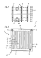
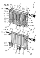
- first panel heater 1 has a front panel 2, which faces away in the assembled state of a wall 3 of a not further shown space and two other identical heating plates 4.
- the front panel 2 is connected at both corners 6 by two Walkerstoffrohre 7 with the heating plates 4.
- the plate heater 1 a first functional connection 8 with a control valve 9 and a second functional connection 10 with a vent valve 11.
- the Control valve 9 and the vent valve 11 are in the FIGS. 6a to 6i shown.
- Both function terminals 8, 10 of the panel heater 1 according to the invention allow the connection of both the control valve 9 and the vent valve 11th
- front panel 2 of the first panel radiator 1 is welded from two half-shells 12, which are deep-drawn profiled steel sheet. Between the half-shells 12 are formed by the profiling on the underside of the panel radiator 1, a lower collecting channel 13, at the top 5, an upper collecting channel 14 and between the collecting channels heating channels 15.
- a spacer 16 is welded to a connecting pipe 17 coming from the inlet connection.
- the spacer 16 is formed as a guide element for the substantially directed introduction of a heating means, not shown in one of the heating channels 15 - which thus acts as riser 18 - trained.
- the guide element has a in the assembled state the riser channel 18 facing the flow opening.
- Two further spacers 19 are welded to not shown Thompsonö Maschinenbaumen at the upper collecting channel 14 of the front panel 2 with the leading to the function terminals 8, 10 Schuffenrohren 7.
- the spacers 19 are sheathed with rubber sleeves and designed as separating elements which separate in the upper collecting channel 14 each one of the heating channels 15, which thus act as further riser channels 20, from the rest. Through the further riser channels 20 and the separating elements 1 heating medium or air from the front panel 2 to the function terminals 8, 10 can flow during operation of the panel heater.
- the non-illustrated heating plates 4 of the panel heater 1 according to the invention are welded from two profiled sheet steel deep-drawn half shells. As in the front panel 2, a lower collecting channel 21, an upper collecting channel 22 and between these heating channels 23 are also formed in the heating plates 4.
- Two spacers 24 are at Thompsonstoffötechnische at the upper collecting channel 22 of the heating plates 4 with the coming of the function terminals 8, 10 Schuffenbachrohren. 7 welded. Through these spacers 24, the heating medium is introduced into the heating plates 4 during operation of the panel heater 1 coming from the control valve 9 or air is passed from the heating plates 4 to the vent valve 11.
- Another spacer 25 is welded at each of a heating medium opening at the lower collecting channel 21 of the heating plates 4 with the leading to the return connection connecting pipe 26. Through these spacers 25, the heating means is derived from the heating plates 4 to the return port during operation of the panel heater 1.
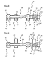
- FIG. 5a shows the in FIG. 4 with "DD" designated section
- FIG. 5b shows the in FIG. 4 with "AA” designated section
- FIG. 5c shows the in FIG. 4 labeled "BB" section through the connector 28th
- the connecting part 28 has a tubular base body 33, which consists of a cast center piece 34 and the two opposing connecting tubes 17, 26.
- the inlet port 29, the return port 30 and a drainage nozzle 35 are attached to the center piece 34 and connected by resistance welding material fit and fluid-tight with the center piece 34.
- the connecting pipes 17, 26 are integrated to the front plate 2 and to the rear heating plates 4.
- the inlet connection 29 has an angular shape and, facing away from the center piece 34, an end 36 which has a bump-shaped bulge by an upsetting operation.
- a threaded connector 37 is inserted and connected to these fluid-tight by resistance welding.
- the threaded connector 37 has an internal thread into which an unillustrated blind plug is screwed.
- the return port 30 is equipped with a threaded connector 38, in the internal thread of a blind plug, not shown, is screwed.
- the central axes 39 of the inlet port 29 and the return port 30 are perpendicular to the central axis 40 of the main body 33.
- the drainage nozzle 35 connects to the inlet port 29 opposite to the middle piece 34 and also has a threaded connector 41 with internal thread.
- connecting channels 42 are formed, which allow a flow of the heating means only from the inlet port 29 to the one connecting pipe 17 and from the second connecting pipe 26 to the return port 30.
- the middle piece 34 has a drainage bore 43 between the inlet connection 29 and the drainage nozzle 35 and a drainage gap 44 between the return connection 30 and the drainage nozzle 35.
- the drainage pipe 35 is with a (in the FIGS. 6a to 6l shown) drainage valve 45 which closes the drainage hole 43 in the operating state. By opening the drainage valve 45, the front plate 2 is dehydrated almost completely at a central location on the bottom 27 of the radiator via the drainage hole 43 and the heating plates 4 via the drainage gap 44.
- connection part 28 has an extension element 46.
- the expansion element 46 has a further inlet connection 47 and a further return connection 48 for the alternative connection to the heating system and a further connection tube 49 for the alternative connection to the heating plate 4.
- the further inflow port 47 has an angular shape and a bone-shaped bulged end 50 by an upsetting operation.
- a threaded connector 51 is inserted and connected to this fluid-tight by resistance welding.
- the threaded connector has an internal thread into which the (in the 6a to 6i shown) supply line 31 is screwed.
- a tubular bypass 52 leads from the further inlet connection 47 through the further return connection 48 to the inlet connection 29.
- the further return port 48 is equipped with a threaded connector 53, in whose internal thread the (in the 6a to 6i shown) return line 32 is screwed.
- the further return port 48 is connected to the further connecting pipe 49.
- the heating medium is introduced into the upper collecting channel 22 of the further heating plate 4 ( Fig. 6f ) flows through the heating channels 23 into the lower collection channel 21 (FIG. Fig. 6g ) and from this to the further return port 48.
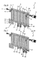
- Fig. 7 shows in the water model a second plate heater according to the invention 54. This corresponds to the first panel heater according to the invention 1.
- the inlet connection 55 of the second panel heater 54 is connected to the supply line 56, the return port 57 to the return line 58.
- the other inlet port 59 and the further return port 60 are, however, closed with blind plugs, not shown.
- the heating means is first passed through the second panel heater 54 as through the first panel heater 1.
- the heating medium in the heating plate 61 flows through the heating channels 62 in the lower collecting channel 63 and from this to the return port 57th
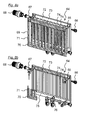
- Fig. 8a to 8e show in the water model a third plate heater 64 according to the invention. This corresponds to the first invention
- the first functional connection 65 is equipped with a vent valve 66, the second functional connection 67 with a control valve 68.
- the heating means is first passed through the third panel heater 64 as through the first panel heater 1.
- the heating means from the lower collecting channel 70 through a further riser 71 ( Fig. 8a ) and out of the further riser 71 to the control valve 68 ( Fig. 8b ).
- the control valve 68 Through the control valve 68, the heating medium is introduced into the upper collecting channel 72 of the heating plate 73 ( Fig. 8c ) flows through the heating channels 74 into the lower collecting channel 75 (FIG. Fig. 8d ) and from this to the further return port 76.
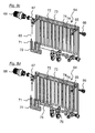
- Fig. 9 shows in the water model a fourth PlattenMapMon invention 77. This corresponds to the third PlattenMapanalysis invention 64.
- the inlet port 78 of the fourth PlattenMap analysess 77 is connected to the feed line 79, the return port 80 to the return line 81.
- the other inlet port 82 and the further return port 83 are closed with blind plugs, not shown.
- the heating means is first passed through the fourth plate heater 77 as through the third plate heater 64. As in Fig. 9 shown, the heating medium flows in the heating plate 84 through the heating channels 85 in the lower collecting channel 86 and from this to the return port 80th
Landscapes
- Engineering & Computer Science (AREA)
- Physics & Mathematics (AREA)
- Thermal Sciences (AREA)
- Chemical & Material Sciences (AREA)
- Combustion & Propulsion (AREA)
- Mechanical Engineering (AREA)
- General Engineering & Computer Science (AREA)
- Domestic Hot-Water Supply Systems And Details Of Heating Systems (AREA)
- Central Heating Systems (AREA)
- Steam Or Hot-Water Central Heating Systems (AREA)
Abstract
Description
- Die Erfindung betrifft zunächst einen Plattenheizkörper mit einer Frontplatte, in der ein unterer Sammelkanal und ein zu diesem parallel verlaufender oberer Sammelkanal und zwischen den Sammelkanälen Heizkanäle ausgebildet sind, mit einem Zulaufanschluss an einer Unterseite des Plattenheizkörpers, wobei mindestens einer der Heizkanäle ein Steigkanal ist, der ein Heizmittel von der Unterseite zu einer Oberseite des Plattenheizkörpers leitet, und mit einem Regelventil an der Oberseite, das einen Volumenstrom des Heizmittels von der Frontplatte in eine hintere Heizplatte des Plattenheizkörpers regelt. Weiterhin betrifft die Erfindung ein Verfahren zum Leiten eines Heizmittels durch einen solchen Plattenheizkörper.
- Verfahren und Plattenheizkörper der vorgenannten Art sind unter der Bezeichnung "serielle Heizkörper" allgemein bekannt. Beispielhaft vermeidet der Hersteller H.M., Dingelstädt/DE (www.muhr.net) mit dem am Markt unter der Produktbezeichnung "Centara" angebotenen Zweiplattenheizkörper separate Rohrleitungen, indem das Heizmittel in den unteren Sammelkanal der Frontplatte eingeleitet wird, die Heizkanäle zum oberen Sammelkanal durchströmt und aus dem oberen Sammelkanal über das Regelventil in die weitere Heizplatte - mit umgekehrter Durchströmung zum Rücklaufanschluss-geleitet wird.
- Die bekannten seriellen Plattenheizkörper weisen einen Zulaufanschluss seitlich (meist mit Blick aus dem zu heizenden Raum rechts, selten links am Heizkörper) oder mittig an der Unterseite auf. Der seitliche Anschluss ist Standard in vielen Altbauten, der mittige Anschluss setzt sich zunehmend für Neubauten durch. Der Hersteller für Installateure, die sowohl Altbauten modernisieren als auch Neubauten ausrüsten, muss beide (oder sogar drei) Modelle für jedes Maß produzieren, der Installateur muss entsprechend Lagerplatz bereitstellen.
- Im weiteren Umfeld der Erfindung offenbart
DE 10 2007 020 628 A1 einen Plattenheizkörper mit parallel durchströmten Heizplatten, der eine Anschlussgarnitur mit alternativen Zulauf- und Rücklaufanschlüssen aufweist, wobei die Zulaufanschlüsse durch einen Kanal verbunden sind und nur der seitliche Zulaufanschluss mit dem Regelventil verbunden ist. Die Rücklaufanschlüsse sind mit beiden Heizplatten verbunden. - Der Erfindung liegt die Aufgabe zugrunde, die Modellvielfalt zu verringern.
- Ausgehend von dem bekannten Plattenheizkörper wird nach der Erfindung vorgeschlagen, dass dieser einen alternativen Zulaufanschluss an der Unterseite aufweist, von dem das Heizmittel in die Frontplatte leitbar ist. Ein erfindungsgemäßer Plattenheizkörper kann dann alternativ über einen der beiden Zulaufanschlüsse mit dem Heizmittel beaufschlagt werden. Weist ein erfindungsgemäßer Plattenheizkörper auch alternative Rücklaufanschlüsse auf, so kann über diese alternativ das rücklaufende Heizmedium aus dem erfindungsgemäßen Plattenheizkörper abgeführt werden.
- Vorzugsweise weist ein erfindungsgemäßer Plattenheizkörper einen Kanal zwischen dem Zulaufanschluss und dem alternativen Zulaufanschluss auf, der das Heizmittel von dem Zulaufanschluss zu dem alternativen Zulaufanschluss leitet, wobei der Steigkanal das Heizmittel von dem alternativen Zulaufanschluss zu der Oberseite leitet. An einem solchen erfindungsgemäßen Plattenheizkörper muss nur der alternative Zulaufanschluss mit dem der Frontplatte verbunden werden. Weist ein erfindungsgemäßer Plattenheizkörper mit alternativen Rücklaufanschlüssen darüber hinaus einen Kanal zwischen diesen auf, so muss auch nur einer der Rücklaufanschlüsse mit der Heizplatte verbunden werden.
- Alternativ können auch die Zulaufanschlüsse eines erfindungsgemäßen Plattenheizkörpers unverbunden sein, so dass bei Mittenanschluss das Heizmedium in einen mittigen Steigkanal und bei seitlichem Anschluss in einen seitlichen Steigkanal der Frontplatte eingeleitet wird.
- Ein erfindungsgemäßer Plattenheizkörper mit einem Kanal zwischen den Zulaufanschlüssen weist besonders bevorzugt ein Anschlussteil mit dem Zulaufanschluss, einem Rücklaufanschluss, dem alternativen Zulaufanschluss und einem alternativen Rücklaufanschluss, sowie mit einem ersten Verbindungsrohr, mittels dessen die Frontplatte mit dem alternativen Zulaufanschluss verbunden ist, mit einem zweiten Verbindungsrohr, mittels dessen die Heizplatte mit dem alternativen Rücklaufanschluss verbunden ist und mit einem durch den Rücklaufanschluss geführten Bypass, mittels dessen der Zulaufanschluss mit dem alternativen Zulaufanschluss verbunden ist. Ein solches Anschlussteil weist vorteilhafter Weise ein gegossenes Mittelstück auf, in das die Heizmittelkanäle eingeformt sind.
- Ausgehend von den bekannten Verfahren wird nach der Erfindung vorgeschlagen, dass das Heizmittel ausgehend von dem Zulaufanschluss durch einen alternativen Zulaufanschluss in die Frontplatte geleitet wird. Das erfindungsgemäße Verfahren wird mit einem erfindungsgemäßen Plattenheizkörper ausgeführt und zeichnet sich durch die dort aufgeführten Vorteile aus.
- Die Erfindung wird nachfolgend anhand eines Ausführungsbeispiels erläutert. Es zeigen
- Fig. 1
- einen ersten erfindungsgemäßen Plattenheizkörper,
- Fig. 2
- einen Schnitt einer Frontplatte des ersten Plattenheizkörpers und
- Fig. 3
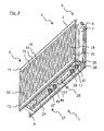
- den ersten Plattenheizkörper in einer perspektivischen Ansicht,
- Fig. 4
- ein Anschlussteil des ersten Plattenheizkörpers und
- Fig. 5a-c
- drei Schnitte durch das Anschlussteil,
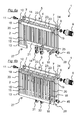
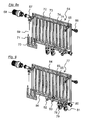
- Fig. 6a-i
- neun Schritte einer Befüllung des ersten Plattenheizkörpers,
- Fig. 7
- einen letzten Schritt der Befüllung eines zweiten erfindungsgemäßen Plattenheizkörpers,
- Fig. 8a-e
- fünf Schritte einer Befüllung eines dritten erfindungsgemäßen Plattenheizkörpers und
- Fig. 9
- einen letzten Schritt der Befüllung eines vierten erfindungsgemäßen Plattenheizkörpers.
- Der in den
Figuren 1 bis 3 gezeigte erste erfindungsgemäße Plattenheizkörper 1 weist eine Frontplatte 2, die im montierten Zustand einer Wand 3 eines nicht weiter dargestellten Raumes abgewandt ist und zwei weitere, identische Heizplatten 4 auf. - An einer Oberseite 5 des Plattenheizkörpers 1 ist die Frontplatte 2 an beiden Ecken 6 durch zwei Heizmittelrohre 7 mit den Heizplatten 4 verbunden. An diesen Heizmittelrohren 7 weist der Plattenheizkörper 1 einen ersten Funktionsanschluss 8 mit einem Regelventil 9 und einen zweiten Funktionsanschluss 10 mit einem Entlüftungsventil 11 auf. (Das Regelventil 9 und das Entlüftungsventil 11 sind in den
Figuren 6a bis 6i dargestellt.) Beide Funktionsanschlüsse 8, 10 des erfindungsgemäßen Plattenheizkörpers 1 ermöglichen den Anschluss sowohl des Regelventils 9 als auch des Entlüftungsventils 11. - Die in
Figur 2 im Schnitt dargestellte Frontplatte 2 des ersten Plattenheizkörpers 1 ist aus zwei Halbschalen 12 verschweißt, die aus Stahlblech profiliert tiefgezogen sind. Zwischen den Halbschalen 12 sind durch die Profilierung an der Unterseite des Plattenheizkörpers 1 ein unterer Sammelkanal 13, an der Oberseite 5 ein oberer Sammelkanal 14 und zwischen den Sammelkanälen Heizkanäle 15 ausgebildet. - An einer nicht dargestellten Heizmittelöffnung am unteren Sammelkanal 13 der Frontplatte 2 ist ein Abstandhalter 16 mit einem vom Zulaufanschluss kommenden Verbindungsrohr 17 verschweißt. Der Abstandhalter 16 ist als Leitelement für die im Wesentlichen gerichtete Einleitung eines nicht dargestellten Heizmittels in einen der Heizkanäle 15 - der damit als Steigkanal 18 fungiert -ausgebildet. Das Leitelement weist eine im montierten Zustand dem Steigkanal 18 zugewandte Durchflussöffnung auf.
- Zwei weitere Abstandhalter 19 sind an gleichfalls nicht dargestellten Heizmittelöffnungen am oberen Sammelkanal 14 der Frontplatte 2 mit den zu den Funktionsanschlüssen 8, 10 führenden Heizmittelrohren 7 verschweißt. Die Abstandhalter 19 sind mit Gummimanschetten ummantelt und als Trennelemente ausgebildet, die im oberen Sammelkanal 14 jeweils einen der Heizkanäle 15, die damit als weitere Steigkanäle 20 fungieren, von den übrigen abtrennen. Durch die weiteren Steigkanäle 20 und die Trennelemente können im Betrieb des Plattenheizkörpers 1 Heizmittel oder Luft aus der Frontplatte 2 zu den Funktionsanschlüssen 8, 10 strömen.
- Auch die nicht geschnitten dargestellten Heizplatten 4 des erfindungsgemäßen Plattenheizkörpers 1 sind aus je zwei profiliert aus Stahlblech tiefgezogenen Halbschalen verschweißt. Wie in der Frontplatte 2 sind auch in den Heizplatten 4 je ein unterer Sammelkanal 21, ein oberer Sammelkanal 22 und zwischen diesen Heizkanäle 23 ausgebildet.
- Zwei Abstandhalter 24 sind an Heizmittelöffnungen am oberen Sammelkanal 22 der Heizplatten 4 mit den von den Funktionsanschlüssen 8, 10 kommenden Heizmittelrohren 7 verschweißt. Durch diese Abstandhalter 24 wird im Betrieb des Plattenheizkörpers 1 von dem Regelventil 9 kommend das Heizmittel in die Heizplatten 4 eingeleitet oder Luft aus den Heizplatten 4 zu dem Entlüftungsventil 11 geführt.
- Ein weiterer Abstandhalter 25 ist jeweils an einer Heizmittelöffnung am unteren Sammelkanal 21 der Heizplatten 4 mit dem zu dem Rücklaufanschluss führenden Verbindungsrohr 26 verschweißt. Durch diese Abstandhalter 25 wird im Betrieb des Plattenheizkörpers 1 das Heizmittel aus den Heizplatten 4 zu dem Rücklaufanschluss abgeleitet.
- An einer Unterseite 27, die im montierten Zustand einem nicht dargestellten Boden des Raumes zugewandt ist, weist der Plattenheizkörper 1 das in den
Figuren 4 und 5a bis 5c gezeigte Anschlussteil 28 mit einen Zulaufanschluss 29 und einen Rücklaufanschluss 30 zum Anschluss an eine in dem Raum vorbereitete Zulaufleitung 31 und eine Rücklaufleitung 32 (dargestellt in denFig. 6a bis 6i ) des Heizungssystems auf.Figur 5a zeigt den inFigur 4 mit "D-D" bezeichneten Schnitt,Figur 5b zeigt den inFigur 4 mit "A-A" bezeichneten Schnitt undFigur 5c zeigt den inFigur 4 mit "B-B" bezeichneten Schnitt durch das Anschlussteil 28. - Das Anschlussteil 28 weist einen rohrförmigen Grundkörper 33 auf, der aus einem gegossenen Mittelstück 34 und den zwei einander gegenüber liegenden Verbindungsrohren 17, 26 besteht. Darüber hinaus sind an das Mittelstück 34 der Zulaufanschluss 29, der Rücklaufanschluss 30 und ein Entwässerungsstutzen 35 angesetzt und durch Widerstandsschweißen stoffschlüssig und fluiddicht mit dem Mittelstück 34 verbunden. In das Anschlussteil 28 sind darüber hinaus die Verbindungsrohre 17, 26 zu der Frontplatte 2 und zu den hinteren Heizplatten 4 integriert.
- Der Zulaufanschluss 29 weist eine winkelförmige Gestalt und dem Mittelstück 34 abgewandt ein durch einen Stauchvorgang knochenförmig ausgewölbtes Ende 36 auf. In das Ende 36 ist ein Gewindestutzen 37 eingesetzt und an diesen durch Widerstandsschweißen fluiddicht angeschlossen. Der Gewindestutzen 37 weist ein Innengewinde auf, in das ein nicht dargestellter Blindstopfen eingeschraubt ist.
- Auch der Rücklaufanschluss 30 ist mit einem Gewindestutzen 38 ausgestattet, in dessen Innengewinde ein nicht dargestellter Blindstopfen eingeschraubt ist. Die Mittelachsen 39 des Zulaufanschlusses 29 und des Rücklaufanschlusses 30 stehen senkrecht auf der Mittelachse 40 des Grundkörpers 33. Der Entwässerungsstutzen 35 schließt dem Zulaufanschluss 29 gegenüber an das Mittelstück 34 an und weist gleichfalls einen Gewindestutzen 41 mit Innengewinde auf.
- In das Mittelstück 34 sind Verbindungskanäle 42 eingeformt, die einen Durchfluss des Heizmittels nur von dem Zulaufanschluss 29 zu dem einen Verbindungsrohr 17 sowie von dem zweiten Verbindungsrohr 26 zu dem Rücklaufanschluss 30 erlauben.
- Ferner weist das Mittelstück 34 eine Entwässerungsbohrung 43 zwischen dem Zulaufanschluss 29 und dem Entwässerungsstutzen 35 sowie eine Entwässerungsspalt 44 zwischen dem Rücklaufanschluss 30 und dem Entwässerungsstutzen 35 auf. Der Entwässerungsstutzen 35 ist mit einem (in den
Figuren 6a bis 6l dargestellten) Entwässerungsventil 45 versehen, das im Betriebszustand die Entwässerungsbohrung 43 verschließt. Durch Öffnen des Entwässerungsventils 45 werden an einem zentralen Ort an der Unterseite 27 des Heizkörpers über die Entwässerungsbohrung 43 die Frontplatte 2 und über den Entwässerungsspalt 44 die Heizplatten 4 nahezu vollständig entwässert. - Weiterhin weist das Anschlussteil 28 ein Erweiterungselement 46 auf. Das Erweiterungselement 46 weist einen weiteren Zulaufanschluss 47 und einen weiteren Rücklaufanschluss 48 zum alternativen Anschluss an das Heizungssystem sowie ein weiteres Verbindungsrohr 49 zum alternativen Anschluss an die Heizplatte 4 auf.
- Der weitere Zulaufanschluss 47 weist eine winkelförmige Gestalt und ein durch einen Stauchvorgang knochenförmig ausgewölbtes Ende 50 auf. In das Ende 50 ist wiederum ein Gewindestutzen 51 eingesetzt und an diesen durch Widerstandsschweißen fluiddicht angeschlossen. Der Gewindestutzen weist ein Innengewinde auf, in das die (in den
Fig. 6a bis 6i dargestellte) Zulaufleitung 31 eingeschraubt ist. In dem Erweiterungselement 46 führt ein rohrförmiger Bypass 52 von dem weiteren Zulaufanschluss 47 durch den weiteren Rücklaufanschluss 48 zu dem Zulaufanschluss 29. - Auch der weitere Rücklaufanschluss 48 ist mit einem Gewindestutzen 53 ausgestattet, in dessen Innengewinde die (in den
Fig. 6a bis 6i dargestellte) Rücklaufleitung 32 eingeschraubt ist. Der weitere Rücklaufanschluss 48 ist mit dem weiteren Verbindungsrohr 49 verbunden. - Die
Figuren 6a bis 6l illustrieren im Wassermodell anhand der verschiedenen Stadien einer Heizmittelfront beim Befüllen des ersten Plattenheizkörpers 1 ein erstes erfindungsgemäßes Verfahren. Hierbei ist vereinfachend nur eine der Heizplatten 4 dargestellt: - Das Heizmittel wird zunächst aus dem Zulaufanschluss 29 oder aus dem weiteren Zulaufanschluss 47 in die Frontplatte 2 (
Fig. 6a ), dort durch den Steigkanal 18 zum oberen Sammelkanal 14 (Fig. 6b ) und aus dem oberen Sammelkanal 14 durch die Heizkanäle 15 zum unteren Sammelkanal 13 (Fig. 6c ), aus dem unteren Sammelkanal 13 durch einen weiteren Steigkanal 20 (Fig. 6d ) und aus dem weiteren Steigkanal 20 zum Regelventil 9 geführt (Fig. 6e ). - Durch das Regelventil 9 wird das Heizmittel in den oberen Sammelkanal 22 der weiteren Heizplatte 4 eingeleitet (
Fig. 6f ), strömt durch die Heizkanäle 23 in den unteren Sammelkanal 21 (Fig. 6g ) und aus diesem zum weiteren Rücklaufanschluss 48. -
Fig. 7 zeigt im Wassermodell einen zweiten erfindungsgemäßen Plattenheizkörper 54. Dieser entspricht dem ersten erfindungsgemäßen Plattenheizkörper 1. Der Zulaufanschluss 55 des zweiten Plattenheizkörpers 54 ist aber mit der Zulaufleitung 56, der Rücklaufanschluss 57 mit der Rücklaufleitung 58 verbunden. Der weitere Zulaufanschluss 59 und der weitere Rücklaufanschluss 60 sind dagegen mit nicht dargestellten Blindstopfen verschlossen. - In einem zweiten erfindungsgemäßen Verfahren wird das Heizmittel durch den zweiten Plattenheizkörper 54 zunächst wie durch den ersten Plattenheizkörper 1 geleitet. Wie in
Fig. 7 dargestellt, strömt das Heizmittel in der Heizplatte 61 durch die Heizkanäle 62 in den unteren Sammelkanal 63 und aus diesem zum Rücklaufanschluss 57. - Die
Fig. 8a bis 8e zeigen im Wassermodell einen dritten erfindungsgemäßen Plattenheizkörper 64. Dieser entspricht dem ersten erfindungsgemäßen - Plattenheizkörper 1. Der erste Funktionsanschluss 65 ist mit einem Entlüftungsventil 66, der zweite Funktionsanschluss 67 mit einem Regelventil 68 ausgerüstet. In einem dritten erfindungsgemäßen Verfahren wird das Heizmittel durch den dritten Plattenheizkörper 64 zunächst wie durch den ersten Plattenheizkörper 1 geleitet.
- In der Frontplatte 69 wird das Heizmittel aus dem unteren Sammelkanal 70 durch einen weiteren Steigkanal 71 (
Fig. 8a ) und aus dem weiteren Steigkanal 71 zum Regelventil 68 geführt (Fig. 8b ). Durch das Regelventil 68 wird das Heizmittel in den oberen Sammelkanal 72 der Heizplatte 73 eingeleitet (Fig. 8c ), strömt durch die Heizkanäle 74 in den unteren Sammelkanal 75 (Fig. 8d ) und aus diesem zum weiteren Rücklaufanschluss 76. -
Fig. 9 zeigt im Wassermodell einen vierten erfindungsgemäßen Plattenheizkörper 77. Dieser entspricht dem dritten erfindungsgemäßen Plattenheizkörper 64. Der Zulaufanschluss 78 des vierten Plattenheizkörpers 77 ist aber mit der Zulaufleitung 79, der Rücklaufanschluss 80 mit der Rücklaufleitung 81 verbunden. Der weitere Zulaufanschluss 82 und der weitere Rücklaufanschluss 83 sind dagegen mit nicht dargestellten Blindstopfen verschlossen. - In einem vierten erfindungsgemäßen Verfahren wird das Heizmittel durch den vierten Plattenheizkörper 77 zunächst wie durch den dritten Plattenheizkörper 64 geleitet. Wie in
Fig. 9 dargestellt, strömt das Heizmittel in der Heizplatte 84 durch die Heizkanäle 85 in den unteren Sammelkanal 86 und aus diesem zum Rücklaufanschluss 80. -
- 1
- Plattenheizkörper
- 2
- Frontplatte
- 3
- Wand
- 4
- Heizplatte
- 5
- Oberseite
- 6
- Ecke
- 7
- Heizmittelrohr
- 8
- Funktionsanschluss
- 9
- Regelventil
- 10
- Funktionsanschluss
- 11
- Entlüftungsventil 66
- 12
- Halbschale
- 13
- unterer Sammelkanal
- 14
- oberer Sammelkanal
- 15
- Heizkanal
- 16
- Abstandhalter
- 17
- Verbindungsrohr
- 18
- Steigkanal
- 19
- Abstandhalter
- 20
- Steigkanal
- 21
- unterer Sammelkanal
- 22
- oberer Sammelkanal
- 23
- Heizkanal
- 24
- Abstandhalter
- 25
- Abstandhalter
- 26
- Verbindungsrohr
- 27
- Unterseite
- 28
- Anschlussteil
- 29
- Zulaufanschluss
- 30
- Rücklaufanschluss
- 31
- Zulaufleitung
- 32
- Rücklaufleitung
- 33
- Grundkörper
- 34
- Mittelstück
- 35
- Entwässerungsstutzen
- 36
- Ende
- 37
- Gewindestutzen
- 38
- Gewindestutzen
- 39
- Mittelachse
- 40
- Mittelachse
- 41
- Gewindestutzen
- 42
- Verbindungskanal
- 43
- Entwässerungsbohrung
- 44
- Entwässerungsspalt
- 45
- Entwässerungsventil
- 46
- Erweiterungselement
- 47
- Zulaufanschluss
- 48
- Rücklaufanschluss
- 49
- Verbindungsrohr
- 50
- Ende
- 51
- Gewindestutzen
- 52
- Bypass
- 53
- Gewindestutzen
- 54
- Plattenheizkörper
- 55
- Zulaufanschluss
- 56
- Zulaufleitung
- 57
- Rücklaufanschluss
- 58
- Rücklaufleitung
- 59
- Zulaufanschluss
- 60
- Rücklaufanschluss
- 61
- Heizplatte
- 62
- Heizkanal
- 63
- unterer Sammelkanal
- 64
- Plattenheizkörper
- 65
- Funktionsanschluss
- 66
- Entlüftungsventil
- 67
- Funktionsanschluss
- 68
- Regelventil
- 69
- Frontplatte
- 70
- unterer Sammelkanal
- 71
- Steigkanal
- 72
- oberer Sammelkanal
- 73
- Heizplatte
- 74
- Heizkanal
- 75
- unterer Sammelkanal
- 76
- Rücklaufanschluss
- 77
- Plattenheizkörper
- 78
- Zulaufanschluss
- 79
- Zulaufleitung
- 80
- Rücklaufanschluss
- 81
- Rücklaufleitung
- 82
- Zulaufanschluss
- 83
- Rücklaufanschluss
- 84
- Heizplatte
- 85
- Heizkanal
- 86
- unterer Sammelkanal
Claims (4)
- Plattenheizkörper (1, 54, 64, 77) mit einer Frontplatte (2, 69), in der ein unterer Sammelkanal (13, 70) und ein zu diesem parallel verlaufender oberer Sammelkanal (14) und zwischen den Sammelkanälen Heizkanäle (15) ausgebildet sind, mit einem Zulaufanschluss (47, 59, 82) an einer Unterseite (27) des Plattenheizkörpers (1, 54, 64, 77), wobei mindestens einer der Heizkanäle (15) ein Steigkanal (18, 71) ist, der ein Heizmittel von der Unterseite (27) zu einer Oberseite (5) des Plattenheizkörpers (1, 54, 64, 77) leitet, und mit einem Regelventil (9, 68) an der Oberseite (5), das einen Volumenstrom des Heizmittels von der Frontplatte (2, 69) in eine hintere Heizplatte (4, 61, 73, 84) des Plattenheizkörpers (1, 54, 64, 77) regelt, gekennzeichnet durch einen alternativen Zulaufanschluss (29, 55, 78) an der Unterseite (27), von dem das Heizmittel in die Frontplatte (2, 69) leitbar ist.
- Plattenheizkörper (1, 54, 64, 77) nach dem vorgenannten Anspruch, gekennzeichnet durch einen Kanal zwischen dem Zulaufanschluss (47, 59, 82) und dem alternativen Zulaufanschluss (29, 55, 78), der das Heizmittel von dem
Zulaufanschluss (47, 59, 82) zu dem alternativen Zulaufanschluss (29, 55, 78) leitet, wobei der Steigkanal (18, 71) das Heizmittel von dem alternativen Zulaufanschluss (29, 55, 78) zu der Oberseite (5) leitet. - Plattenheizkörper (1, 54, 64, 77) nach dem vorgenannten Anspruch, gekennzeichnet durch ein Anschlussteil (28) mit dem Zulaufanschluss (47, 59, 82), einem Rücklaufanschluss (48, 60, 83), dem alternativen Zulaufanschluss (29, 55, 78) und einem alternativen Rücklaufanschluss (30, 57, 80), sowie mit einem ersten Verbindungsrohr (17), mittels dessen die Frontplatte (2, 69) mit dem alternativen Zulaufanschluss (29, 55, 78) verbunden ist, mit einem zweiten Verbindungsrohr (26), mittels dessen die Heizplatte (4, 61, 73, 84) mit dem alternativen Rücklaufanschluss (30, 57, 80) verbunden ist und mit einem durch den Rücklaufanschluss (48, 60, 83) geführten Bypass (52), mittels dessen der Zulaufanschluss (47, 59, 82) mit dem alternativen Zulaufanschluss (29, 55, 78) verbunden ist.
- Verfahren zum Leiten eines Heizmittels durch einen Plattenheizkörper (1, 54, 64, 77) mit einer Frontplatte (2, 69), in der ein unterer Sammelkanal (13, 70) und ein zu diesem parallel verlaufender oberer Sammelkanal (14) und zwischen den Sammelkanälen Heizkanäle (15) ausgebildet sind, wobei das Heizmittel ausgehend von einem Zulaufanschluss (47, 59, 82) an einer Unterseite (27) des Plattenheizkörpers (1, 54, 64, 77) in die Frontplatte (2, 69) geleitet wird, wobei mindestens einer der Heizkanäle (15) ein Steigkanal (18, 71) ist, der das Heizmittel ausgehend von der Unterseite (27) durch den Steigkanal (18, 71) zu der Oberseite (5) leitet, und wobei ein Regelventil (9, 68) an der Oberseite (5) einen Volumenstrom des Heizmittels von der Frontplatte (2, 69) in eine hintere Heizplatte (4, 61, 73, 84) regelt, dadurch gekennzeichnet, dass das Heizmittel ausgehend von dem Zulaufanschluss (47, 59, 82) durch einen alternativen Zulaufanschluss (29, 55, 78) in die Frontplatte (2, 69) geleitet wird.
Applications Claiming Priority (1)
| Application Number | Priority Date | Filing Date | Title |
|---|---|---|---|
| DE102010037526A DE102010037526A1 (de) | 2010-09-14 | 2010-09-14 | Plattenheizkörper und Verfahren zum Leiten eines Heizmittels |
Publications (3)
| Publication Number | Publication Date |
|---|---|
| EP2428748A2 true EP2428748A2 (de) | 2012-03-14 |
| EP2428748A3 EP2428748A3 (de) | 2015-08-05 |
| EP2428748B1 EP2428748B1 (de) | 2017-03-08 |
Family
ID=44651045
Family Applications (1)
| Application Number | Title | Priority Date | Filing Date |
|---|---|---|---|
| EP11175370.3A Active EP2428748B1 (de) | 2010-09-14 | 2011-07-26 | Plattenheizkörper und Verfahren zum Leiten eines Heizmittels |
Country Status (2)
| Country | Link |
|---|---|
| EP (1) | EP2428748B1 (de) |
| DE (1) | DE102010037526A1 (de) |
Cited By (3)
| Publication number | Priority date | Publication date | Assignee | Title |
|---|---|---|---|---|
| EP3109561A1 (de) | 2015-06-23 | 2016-12-28 | Rettig ICC B.V. | Heizkörper |
| EP3628935A1 (de) | 2018-09-28 | 2020-04-01 | Rettig Austria GmbH | Heizkörper |
| WO2023083395A1 (en) * | 2021-11-15 | 2023-05-19 | Korado, A.S. | Set for heating water distribution to and from a two-plate or single-plate radiator |
Families Citing this family (4)
| Publication number | Priority date | Publication date | Assignee | Title |
|---|---|---|---|---|
| WO2020139213A1 (en) * | 2018-12-28 | 2020-07-02 | Radyal Isitma Sistemleri Anonim Sirketi | A panel radiator of guiding heating medium in the heating channels |
| EP4473253A4 (de) * | 2022-02-07 | 2025-12-17 | Commital Isi Ekipmanlari Kalip Sanayi Ve Tic Ltd Sti | Rohrverbindungsgruppe mit anschlussstücken aus draht für plattenheizkörper mit 8-zu- und -auslass |
| EP4479688A4 (de) * | 2022-02-16 | 2025-10-22 | Commital Isi Ekipmanlari Kalip Sanayi Ve Tic Ltd Sti | Rohrlose verbindergruppe aus draht für plattenheizkörper mit 8 ein- und auslässen |
| EP4600595A1 (de) | 2024-02-08 | 2025-08-13 | Commital isi Ekipmanlari Kalip Sanayi Ve Tic. Ltd. Sti | Heizkörper |
Citations (1)
| Publication number | Priority date | Publication date | Assignee | Title |
|---|---|---|---|---|
| DE102007020628A1 (de) | 2007-04-30 | 2008-11-06 | Hans Berg Gmbh & Co. Kg | Anschlussgarnitur für einen Plattenheizkörper |
Family Cites Families (7)
| Publication number | Priority date | Publication date | Assignee | Title |
|---|---|---|---|---|
| DE19621137C2 (de) * | 1996-05-24 | 2000-08-03 | Kermi Gmbh | Adapter für mittigen Anschluß von Heizkörpern |
| DE19709534A1 (de) * | 1997-03-10 | 1998-09-24 | Oventrop Sohn Kg F W | Von Fluid als Wärmeträger durchströmbarer Heizkörper |
| BE1014939A5 (fr) * | 2000-09-11 | 2004-07-06 | Namur Roger | Radiateur a panneaux "anti court-circuit" pour chauffage central. |
| AT412580B (de) * | 2001-08-23 | 2005-04-25 | Vogel & Noot Waermetechnik Ag | Paneel- bzw. plattenheizkörper |
| EP1965148A1 (de) * | 2007-03-02 | 2008-09-03 | Van Marcke Logistics N.V. | Heizkörper |
| DE102007036141A1 (de) * | 2007-07-31 | 2009-02-05 | Kermi Gmbh | Heizkörper |
| DE202007010726U1 (de) * | 2007-07-31 | 2007-09-27 | Kermi Gmbh | Heizkörper mit Teillastfunktion |
-
2010
- 2010-09-14 DE DE102010037526A patent/DE102010037526A1/de not_active Ceased
-
2011
- 2011-07-26 EP EP11175370.3A patent/EP2428748B1/de active Active
Patent Citations (1)
| Publication number | Priority date | Publication date | Assignee | Title |
|---|---|---|---|---|
| DE102007020628A1 (de) | 2007-04-30 | 2008-11-06 | Hans Berg Gmbh & Co. Kg | Anschlussgarnitur für einen Plattenheizkörper |
Cited By (5)
| Publication number | Priority date | Publication date | Assignee | Title |
|---|---|---|---|---|
| EP3109561A1 (de) | 2015-06-23 | 2016-12-28 | Rettig ICC B.V. | Heizkörper |
| EP3628935A1 (de) | 2018-09-28 | 2020-04-01 | Rettig Austria GmbH | Heizkörper |
| WO2023083395A1 (en) * | 2021-11-15 | 2023-05-19 | Korado, A.S. | Set for heating water distribution to and from a two-plate or single-plate radiator |
| PL132201U1 (pl) * | 2021-11-15 | 2025-02-03 | Korado A.S. | Zestaw do rozprowadzania wody grzewczej do i z grzejnika dwupłytowego lub jednopłytowego |
| AT18446U1 (de) * | 2021-11-15 | 2025-04-15 | Korado As | Satz zur Heizwasserverteilung zu und von einem Zweiplatten- oder Einplattenheizkörper |
Also Published As
| Publication number | Publication date |
|---|---|
| DE102010037526A1 (de) | 2012-03-15 |
| EP2428748A3 (de) | 2015-08-05 |
| EP2428748B1 (de) | 2017-03-08 |
Similar Documents
| Publication | Publication Date | Title |
|---|---|---|
| EP2428748B1 (de) | Plattenheizkörper und Verfahren zum Leiten eines Heizmittels | |
| EP2525126B1 (de) | Verbinder für eine beheizbare Fluidleitung und beheizbare Fluidleitung | |
| DE112020002584T5 (de) | Verteilerrohre für eine Verteilerrohrleitung | |
| DE202007005330U1 (de) | Heizkörper, insbesondere Röhrenheizkörper | |
| AT17510U1 (de) | Wohnungsanschlussstation | |
| EP2520868B1 (de) | Plattenheizkörper | |
| EP2402676B1 (de) | Verfahren zum Leiten eines Heizmittels und Plattenheizkörper | |
| EP1884723B1 (de) | Baueinheit | |
| EP2479510A2 (de) | Ventilgarnitur sowie Heizkörper mit einer solchen | |
| DE102018113818A1 (de) | Dunstabzugssystem | |
| DE10223790B4 (de) | Plattenheizkörper | |
| EP1014005B1 (de) | Einrichtung für eine Heizungsanlage, mit einer hydraulischen Weiche und mit einem Heizkreisverteiler | |
| DE19832051C2 (de) | Heiz- bzw. Kühlkörper-Verteileranordnung | |
| EP2023058B1 (de) | Anschlussstück für einen eine Innenzirkulationsleitung aufweisenden Flüssigkeitskreislauf einer Brauchwasser- oder Heizwasserversorgungsanlage, Leitungsanordnung mit einem solchen Anschlussstück und Verfahren zum Montieren einer solchen Leitungsanordnung | |
| AT516831B1 (de) | Heizkörper | |
| AT412503B (de) | Verteilergruppe für plattenheizkörper | |
| DE10130194C2 (de) | Verfahren zum Anschluß eines Heizkörpers an ein Versorgungsleitungssystem sowie Heizkörper | |
| DE102008026074B3 (de) | Wärmetauscher | |
| EP2653794B1 (de) | Rohrverbinder | |
| AT501107B1 (de) | Thermische solaranlage | |
| DE4426640A1 (de) | Kunststoffrohrmatte zur Kühlung/Heizung und/oder zum Wärmeaustausch | |
| CH693966A5 (de) | Heizkoerper und Anschlussgarnitur. | |
| AT412580B (de) | Paneel- bzw. plattenheizkörper | |
| DE102018100422A1 (de) | Anschluss-Set | |
| EP4327027A1 (de) | Ein- oder mehrreihiger heizkörper |
Legal Events
| Date | Code | Title | Description |
|---|---|---|---|
| AK | Designated contracting states |
Kind code of ref document: A2 Designated state(s): AL AT BE BG CH CY CZ DE DK EE ES FI FR GB GR HR HU IE IS IT LI LT LU LV MC MK MT NL NO PL PT RO RS SE SI SK SM TR |
|
| AX | Request for extension of the european patent |
Extension state: BA ME |
|
| PUAI | Public reference made under article 153(3) epc to a published international application that has entered the european phase |
Free format text: ORIGINAL CODE: 0009012 |
|
| REG | Reference to a national code |
Ref country code: DE Ref legal event code: R079 Ref document number: 502011011777 Country of ref document: DE Free format text: PREVIOUS MAIN CLASS: F24H0009120000 Ipc: F24D0019000000 |
|
| PUAL | Search report despatched |
Free format text: ORIGINAL CODE: 0009013 |
|
| AK | Designated contracting states |
Kind code of ref document: A3 Designated state(s): AL AT BE BG CH CY CZ DE DK EE ES FI FR GB GR HR HU IE IS IT LI LT LU LV MC MK MT NL NO PL PT RO RS SE SI SK SM TR |
|
| AX | Request for extension of the european patent |
Extension state: BA ME |
|
| RIC1 | Information provided on ipc code assigned before grant |
Ipc: F24D 19/00 20060101AFI20150630BHEP |
|
| 17P | Request for examination filed |
Effective date: 20151111 |
|
| RBV | Designated contracting states (corrected) |
Designated state(s): AL AT BE BG CH CY CZ DE DK EE ES FI FR GB GR HR HU IE IS IT LI LT LU LV MC MK MT NL NO PL PT RO RS SE SI SK SM TR |
|
| RAP1 | Party data changed (applicant data changed or rights of an application transferred) |
Owner name: CARADON STELRAD B.V. |
|
| GRAP | Despatch of communication of intention to grant a patent |
Free format text: ORIGINAL CODE: EPIDOSNIGR1 |
|
| STAA | Information on the status of an ep patent application or granted ep patent |
Free format text: STATUS: GRANT OF PATENT IS INTENDED |
|
| INTG | Intention to grant announced |
Effective date: 20161116 |
|
| GRAS | Grant fee paid |
Free format text: ORIGINAL CODE: EPIDOSNIGR3 |
|
| GRAA | (expected) grant |
Free format text: ORIGINAL CODE: 0009210 |
|
| STAA | Information on the status of an ep patent application or granted ep patent |
Free format text: STATUS: THE PATENT HAS BEEN GRANTED |
|
| AK | Designated contracting states |
Kind code of ref document: B1 Designated state(s): AL AT BE BG CH CY CZ DE DK EE ES FI FR GB GR HR HU IE IS IT LI LT LU LV MC MK MT NL NO PL PT RO RS SE SI SK SM TR |
|
| REG | Reference to a national code |
Ref country code: GB Ref legal event code: FG4D Free format text: NOT ENGLISH |
|
| REG | Reference to a national code |
Ref country code: CH Ref legal event code: EP Ref country code: AT Ref legal event code: REF Ref document number: 873881 Country of ref document: AT Kind code of ref document: T Effective date: 20170315 |
|
| REG | Reference to a national code |
Ref country code: IE Ref legal event code: FG4D Free format text: LANGUAGE OF EP DOCUMENT: GERMAN |
|
| REG | Reference to a national code |
Ref country code: DE Ref legal event code: R096 Ref document number: 502011011777 Country of ref document: DE |
|
| REG | Reference to a national code |
Ref country code: NL Ref legal event code: FP |
|
| REG | Reference to a national code |
Ref country code: LT Ref legal event code: MG4D |
|
| REG | Reference to a national code |
Ref country code: FR Ref legal event code: PLFP Year of fee payment: 7 |
|
| PG25 | Lapsed in a contracting state [announced via postgrant information from national office to epo] |
Ref country code: GR Free format text: LAPSE BECAUSE OF FAILURE TO SUBMIT A TRANSLATION OF THE DESCRIPTION OR TO PAY THE FEE WITHIN THE PRESCRIBED TIME-LIMIT Effective date: 20170609 Ref country code: NO Free format text: LAPSE BECAUSE OF FAILURE TO SUBMIT A TRANSLATION OF THE DESCRIPTION OR TO PAY THE FEE WITHIN THE PRESCRIBED TIME-LIMIT Effective date: 20170608 Ref country code: FI Free format text: LAPSE BECAUSE OF FAILURE TO SUBMIT A TRANSLATION OF THE DESCRIPTION OR TO PAY THE FEE WITHIN THE PRESCRIBED TIME-LIMIT Effective date: 20170308 Ref country code: LT Free format text: LAPSE BECAUSE OF FAILURE TO SUBMIT A TRANSLATION OF THE DESCRIPTION OR TO PAY THE FEE WITHIN THE PRESCRIBED TIME-LIMIT Effective date: 20170308 Ref country code: HR Free format text: LAPSE BECAUSE OF FAILURE TO SUBMIT A TRANSLATION OF THE DESCRIPTION OR TO PAY THE FEE WITHIN THE PRESCRIBED TIME-LIMIT Effective date: 20170308 |
|
| PG25 | Lapsed in a contracting state [announced via postgrant information from national office to epo] |
Ref country code: ES Free format text: LAPSE BECAUSE OF FAILURE TO SUBMIT A TRANSLATION OF THE DESCRIPTION OR TO PAY THE FEE WITHIN THE PRESCRIBED TIME-LIMIT Effective date: 20170308 Ref country code: BG Free format text: LAPSE BECAUSE OF FAILURE TO SUBMIT A TRANSLATION OF THE DESCRIPTION OR TO PAY THE FEE WITHIN THE PRESCRIBED TIME-LIMIT Effective date: 20170608 Ref country code: LV Free format text: LAPSE BECAUSE OF FAILURE TO SUBMIT A TRANSLATION OF THE DESCRIPTION OR TO PAY THE FEE WITHIN THE PRESCRIBED TIME-LIMIT Effective date: 20170308 Ref country code: RS Free format text: LAPSE BECAUSE OF FAILURE TO SUBMIT A TRANSLATION OF THE DESCRIPTION OR TO PAY THE FEE WITHIN THE PRESCRIBED TIME-LIMIT Effective date: 20170308 Ref country code: SE Free format text: LAPSE BECAUSE OF FAILURE TO SUBMIT A TRANSLATION OF THE DESCRIPTION OR TO PAY THE FEE WITHIN THE PRESCRIBED TIME-LIMIT Effective date: 20170308 |
|
| PG25 | Lapsed in a contracting state [announced via postgrant information from national office to epo] |
Ref country code: SK Free format text: LAPSE BECAUSE OF FAILURE TO SUBMIT A TRANSLATION OF THE DESCRIPTION OR TO PAY THE FEE WITHIN THE PRESCRIBED TIME-LIMIT Effective date: 20170308 Ref country code: IT Free format text: LAPSE BECAUSE OF FAILURE TO SUBMIT A TRANSLATION OF THE DESCRIPTION OR TO PAY THE FEE WITHIN THE PRESCRIBED TIME-LIMIT Effective date: 20170308 Ref country code: CZ Free format text: LAPSE BECAUSE OF FAILURE TO SUBMIT A TRANSLATION OF THE DESCRIPTION OR TO PAY THE FEE WITHIN THE PRESCRIBED TIME-LIMIT Effective date: 20170308 Ref country code: RO Free format text: LAPSE BECAUSE OF FAILURE TO SUBMIT A TRANSLATION OF THE DESCRIPTION OR TO PAY THE FEE WITHIN THE PRESCRIBED TIME-LIMIT Effective date: 20170308 Ref country code: EE Free format text: LAPSE BECAUSE OF FAILURE TO SUBMIT A TRANSLATION OF THE DESCRIPTION OR TO PAY THE FEE WITHIN THE PRESCRIBED TIME-LIMIT Effective date: 20170308 |
|
| PG25 | Lapsed in a contracting state [announced via postgrant information from national office to epo] |
Ref country code: PL Free format text: LAPSE BECAUSE OF FAILURE TO SUBMIT A TRANSLATION OF THE DESCRIPTION OR TO PAY THE FEE WITHIN THE PRESCRIBED TIME-LIMIT Effective date: 20170308 Ref country code: IS Free format text: LAPSE BECAUSE OF FAILURE TO SUBMIT A TRANSLATION OF THE DESCRIPTION OR TO PAY THE FEE WITHIN THE PRESCRIBED TIME-LIMIT Effective date: 20170708 Ref country code: SM Free format text: LAPSE BECAUSE OF FAILURE TO SUBMIT A TRANSLATION OF THE DESCRIPTION OR TO PAY THE FEE WITHIN THE PRESCRIBED TIME-LIMIT Effective date: 20170308 Ref country code: PT Free format text: LAPSE BECAUSE OF FAILURE TO SUBMIT A TRANSLATION OF THE DESCRIPTION OR TO PAY THE FEE WITHIN THE PRESCRIBED TIME-LIMIT Effective date: 20170710 |
|
| REG | Reference to a national code |
Ref country code: DE Ref legal event code: R097 Ref document number: 502011011777 Country of ref document: DE |
|
| PLBE | No opposition filed within time limit |
Free format text: ORIGINAL CODE: 0009261 |
|
| STAA | Information on the status of an ep patent application or granted ep patent |
Free format text: STATUS: NO OPPOSITION FILED WITHIN TIME LIMIT |
|
| PG25 | Lapsed in a contracting state [announced via postgrant information from national office to epo] |
Ref country code: DK Free format text: LAPSE BECAUSE OF FAILURE TO SUBMIT A TRANSLATION OF THE DESCRIPTION OR TO PAY THE FEE WITHIN THE PRESCRIBED TIME-LIMIT Effective date: 20170308 |
|
| 26N | No opposition filed |
Effective date: 20171211 |
|
| PG25 | Lapsed in a contracting state [announced via postgrant information from national office to epo] |
Ref country code: SI Free format text: LAPSE BECAUSE OF FAILURE TO SUBMIT A TRANSLATION OF THE DESCRIPTION OR TO PAY THE FEE WITHIN THE PRESCRIBED TIME-LIMIT Effective date: 20170308 |
|
| REG | Reference to a national code |
Ref country code: CH Ref legal event code: PL |
|
| REG | Reference to a national code |
Ref country code: IE Ref legal event code: MM4A |
|
| PG25 | Lapsed in a contracting state [announced via postgrant information from national office to epo] |
Ref country code: IE Free format text: LAPSE BECAUSE OF NON-PAYMENT OF DUE FEES Effective date: 20170726 Ref country code: LI Free format text: LAPSE BECAUSE OF NON-PAYMENT OF DUE FEES Effective date: 20170731 Ref country code: CH Free format text: LAPSE BECAUSE OF NON-PAYMENT OF DUE FEES Effective date: 20170731 |
|
| PG25 | Lapsed in a contracting state [announced via postgrant information from national office to epo] |
Ref country code: LU Free format text: LAPSE BECAUSE OF NON-PAYMENT OF DUE FEES Effective date: 20170726 |
|
| REG | Reference to a national code |
Ref country code: FR Ref legal event code: PLFP Year of fee payment: 8 |
|
| PG25 | Lapsed in a contracting state [announced via postgrant information from national office to epo] |
Ref country code: MT Free format text: LAPSE BECAUSE OF FAILURE TO SUBMIT A TRANSLATION OF THE DESCRIPTION OR TO PAY THE FEE WITHIN THE PRESCRIBED TIME-LIMIT Effective date: 20170308 |
|
| PG25 | Lapsed in a contracting state [announced via postgrant information from national office to epo] |
Ref country code: HU Free format text: LAPSE BECAUSE OF FAILURE TO SUBMIT A TRANSLATION OF THE DESCRIPTION OR TO PAY THE FEE WITHIN THE PRESCRIBED TIME-LIMIT; INVALID AB INITIO Effective date: 20110726 Ref country code: MC Free format text: LAPSE BECAUSE OF FAILURE TO SUBMIT A TRANSLATION OF THE DESCRIPTION OR TO PAY THE FEE WITHIN THE PRESCRIBED TIME-LIMIT Effective date: 20170308 |
|
| PG25 | Lapsed in a contracting state [announced via postgrant information from national office to epo] |
Ref country code: CY Free format text: LAPSE BECAUSE OF NON-PAYMENT OF DUE FEES Effective date: 20170308 |
|
| PG25 | Lapsed in a contracting state [announced via postgrant information from national office to epo] |
Ref country code: MK Free format text: LAPSE BECAUSE OF FAILURE TO SUBMIT A TRANSLATION OF THE DESCRIPTION OR TO PAY THE FEE WITHIN THE PRESCRIBED TIME-LIMIT Effective date: 20170308 |
|
| PG25 | Lapsed in a contracting state [announced via postgrant information from national office to epo] |
Ref country code: AL Free format text: LAPSE BECAUSE OF FAILURE TO SUBMIT A TRANSLATION OF THE DESCRIPTION OR TO PAY THE FEE WITHIN THE PRESCRIBED TIME-LIMIT Effective date: 20170308 |
|
| REG | Reference to a national code |
Ref country code: DE Ref legal event code: R082 Ref document number: 502011011777 Country of ref document: DE Representative=s name: BAUER WAGNER PELLENGAHR SROKA PATENT- & RECHTS, DE Ref country code: DE Ref legal event code: R082 Ref document number: 502011011777 Country of ref document: DE Representative=s name: BAUER PSU PARTG MBB, DE |
|
| P01 | Opt-out of the competence of the unified patent court (upc) registered |
Effective date: 20230523 |
|
| PGFP | Annual fee paid to national office [announced via postgrant information from national office to epo] |
Ref country code: NL Payment date: 20250724 Year of fee payment: 15 |
|
| PGFP | Annual fee paid to national office [announced via postgrant information from national office to epo] |
Ref country code: DE Payment date: 20250731 Year of fee payment: 15 |
|
| PGFP | Annual fee paid to national office [announced via postgrant information from national office to epo] |
Ref country code: TR Payment date: 20250709 Year of fee payment: 15 |
|
| PGFP | Annual fee paid to national office [announced via postgrant information from national office to epo] |
Ref country code: BE Payment date: 20250724 Year of fee payment: 15 Ref country code: GB Payment date: 20250722 Year of fee payment: 15 |
|
| PGFP | Annual fee paid to national office [announced via postgrant information from national office to epo] |
Ref country code: FR Payment date: 20250725 Year of fee payment: 15 Ref country code: AT Payment date: 20250718 Year of fee payment: 15 |