EP2428845A2 - Bilderzeugendes System - Google Patents
Bilderzeugendes System Download PDFInfo
- Publication number
- EP2428845A2 EP2428845A2 EP11178618A EP11178618A EP2428845A2 EP 2428845 A2 EP2428845 A2 EP 2428845A2 EP 11178618 A EP11178618 A EP 11178618A EP 11178618 A EP11178618 A EP 11178618A EP 2428845 A2 EP2428845 A2 EP 2428845A2
- Authority
- EP
- European Patent Office
- Prior art keywords
- image forming
- control section
- section
- notification
- adjustment
- Prior art date
- Legal status (The legal status is an assumption and is not a legal conclusion. Google has not performed a legal analysis and makes no representation as to the accuracy of the status listed.)
- Granted
Links
Images


Classifications
-
- G—PHYSICS
- G03—PHOTOGRAPHY; CINEMATOGRAPHY; ANALOGOUS TECHNIQUES USING WAVES OTHER THAN OPTICAL WAVES; ELECTROGRAPHY; HOLOGRAPHY
- G03G—ELECTROGRAPHY; ELECTROPHOTOGRAPHY; MAGNETOGRAPHY
- G03G21/00—Arrangements not provided for by groups G03G13/00 - G03G19/00, e.g. cleaning, elimination of residual charge
- G03G21/14—Electronic sequencing control
-
- G—PHYSICS
- G03—PHOTOGRAPHY; CINEMATOGRAPHY; ANALOGOUS TECHNIQUES USING WAVES OTHER THAN OPTICAL WAVES; ELECTROGRAPHY; HOLOGRAPHY
- G03G—ELECTROGRAPHY; ELECTROPHOTOGRAPHY; MAGNETOGRAPHY
- G03G15/00—Apparatus for electrographic processes using a charge pattern
- G03G15/22—Apparatus for electrographic processes using a charge pattern involving the combination of more than one step according to groups G03G13/02 - G03G13/20
- G03G15/23—Apparatus for electrographic processes using a charge pattern involving the combination of more than one step according to groups G03G13/02 - G03G13/20 specially adapted for copying both sides of an original or for copying on both sides of a recording or image-receiving material
- G03G15/231—Arrangements for copying on both sides of a recording or image-receiving material
- G03G15/238—Arrangements for copying on both sides of a recording or image-receiving material using more than one reusable electrographic recording member, e.g. single pass duplex copiers
-
- G—PHYSICS
- G03—PHOTOGRAPHY; CINEMATOGRAPHY; ANALOGOUS TECHNIQUES USING WAVES OTHER THAN OPTICAL WAVES; ELECTROGRAPHY; HOLOGRAPHY
- G03G—ELECTROGRAPHY; ELECTROPHOTOGRAPHY; MAGNETOGRAPHY
- G03G15/00—Apparatus for electrographic processes using a charge pattern
- G03G15/55—Self-diagnostics; Malfunction or lifetime display
-
- G—PHYSICS
- G03—PHOTOGRAPHY; CINEMATOGRAPHY; ANALOGOUS TECHNIQUES USING WAVES OTHER THAN OPTICAL WAVES; ELECTROGRAPHY; HOLOGRAPHY
- G03G—ELECTROGRAPHY; ELECTROPHOTOGRAPHY; MAGNETOGRAPHY
- G03G2215/00—Apparatus for electrophotographic processes
- G03G2215/00016—Special arrangement of entire apparatus
- G03G2215/00021—Plural substantially independent image forming units in cooperation, e.g. for duplex, colour or high-speed simplex
Definitions
- the present invention relates to an image forming system.
- Japanese Patent Application Laid-Open Publication No. 7-237336 describes a technique in which an intermediate buffer apparatus is provided between two printers, paper on which an image is formed on a front face by a first printer is sent to the intermediate buffer apparatus, and the paper is received by a second printer from the intermediate buffer apparatus and an image is formed on a back face by the second printer.
- suitable double face printing is realized by stopping printing and paper feeding by the first printer or the second printer according to accumulated amount of paper in the intermediate buffer apparatus.
- the present invention has been made in consideration of the above problems, and it is one of main objects to provide an image forming system which can perform adjustment efficiently in any of a plurality of image forming apparatuses.
- an image forming system including:
- control section of the plurality of image forming apparatuses each specify time necessary for the adjustment when there is the notification that the adjustment is performed from the other image forming apparatus, and when the specified time is less than a predetermined judgment time, the driving of the image forming section is not stopped and the image forming section is on standby in a ready state until the adjustment is complete.
- each of the control section of the plurality of image forming apparatuses is able to perform a plurality of types of adjustment, and the control section performs the notification that the adjustment is performed to the other image forming apparatus so that it is possible to specify the type of the adjustment, and when there is a notification from the other image forming apparatus that the adjustment is performed, the control section specifies the time necessary for adjustment from the type of adjustment specified by the notification.
- the control section of an image forming apparatus provided in a downstream side puts the image forming section on standby in the ready state; and when there is a notification that the adjustment is performed from the image forming apparatus provided in the downstream side, when the time specified from the type of adjustment specified from the notification that the adjustment is performed from the image forming apparatus provided in the downstream side is less than the judgment time, the control section of the image forming apparatus provided in the upstream side puts the image forming section on standby in the ready state; and when there is a notification that the adjustment is performed from the image forming apparatus provided in the downstream side, when the time specified from the type of adjustment specified from the notification that the adjustment is performed from the image forming apparatus provided in the downstream side is less than the judgment time, the control section of the image forming apparatus provided in the upstream side puts the image forming section on standby in the ready
- each of the control section of the plurality of image forming apparatuses is able to perform a plurality of types of adjustment, and the control section performs the notification that the adjustment is performed to the other image forming apparatus so that it is possible to specify the type of the adjustment, and when there is a notification from the other image forming apparatus that the adjustment is performed, the control section judges whether or not to put the image forming section in the driving stopped state based on the type of adjustment specified by the notification and when it is judged to put the image forming section in the driving stopped state, the image forming section is put in the driving stopped state, and when it is judged not to put the image forming section in the driving stopped state, the driving of the image forming section is not stopped, and the image forming section is put on standby in the ready state until the adjustment is complete.
- the adjustment is image stabilizing processing to stabilize image forming in the image forming section.
- the image forming system further includes an accumulating apparatus which is provided between the plurality of image forming apparatuses, which receives and accumulates paper discharged from the image forming apparatus provided in an upstream side of a paper conveying direction and which sends out the accumulated paper to an image forming apparatus provided in a downstream side, wherein each of the control section of the plurality of image forming apparatuses discharges the paper on which image forming processing is performed by the image forming section outside the apparatus, and then puts the image forming section in the driving stopped state.
- an accumulating apparatus which is provided between the plurality of image forming apparatuses, which receives and accumulates paper discharged from the image forming apparatus provided in an upstream side of a paper conveying direction and which sends out the accumulated paper to an image forming apparatus provided in a downstream side, wherein each of the control section of the plurality of image forming apparatuses discharges the paper on which image forming processing is performed by the image forming section outside the apparatus, and then puts the image forming section in the driving
- the image forming system 1 of the present embodiment includes a first image forming apparatus 100, a second image forming apparatus 200, an intermediate buffer apparatus 300, a large capacity paper feeding apparatus 400, a relay conveying apparatus 500 and a post processing apparatus 600.
- the image forming system 1 employs a tandem configuration in which these apparatuses are provided in series.
- each component is provided in a following order from an upstream side of a paper conveying direction, the large capacity paper feeding apparatus 400, the second image forming apparatus 200, the intermediate buffer apparatus 300, the first image forming apparatus 100, the relay conveying apparatus 500 and the post processing apparatus 600.
- the image forming system 1 performs image forming in the first image forming apparatus 100 and the second image forming apparatus 200 on paper fed from a paper feeding tray provided in the large capacity paper feeding apparatus 400, the first image forming apparatus 100 and the second image forming apparatus 200, performs predetermined post processing in the post processing apparatus 600 and performs output of the paper (paper discharge).
- the first image forming apparatus 100 and the second image forming apparatus 200 each perform image forming processing on one face of the paper.
- the second image forming apparatus 200 when image forming processing is performed on both faces of the paper, the second image forming apparatus 200 performs the image forming processing on one face of the paper, the intermediate buffer apparatus 300 performs reversing of the front and back of the paper, and the first image forming apparatus 100 performs image forming processing on the reversed paper.
- the first image forming apparatus 100 includes a paper feeding tray 110, a print section 120, conveying path switching sections 130 and 131, an ADF (Auto Document Feeder) 140, an image reading section 150 and an operation/display section 160.
- the first image forming apparatus 100 of the present embodiment is a digital multifunction peripheral including a scanner function, a copying function and a printer function.
- an image forming apparatus which forms a color image of four colors of CMYK or an image forming apparatus which forms a black and white image of one color can be employed.
- the paper feeding tray 110 includes a plurality of trays 110d to 110f, and paper discriminated based on basis weight, size, etc. is stored in each tray according to type as set by the user.
- the paper stored in the paper feeding tray 110 is conveyed through a conveying path with a conveying roller which is not shown and conveyed to the print section 120.
- the print section 120 includes an image forming section 121 and a fixing section 122 and performs image forming processing of an electro-photographic method based on the input job data and image data.
- the image forming section 121 scans a surface of a rotating image carrier uniformly charged by a charging section with a laser light source and a polygon mirror, and forms an electrostatic latent image corresponding to a document image on a face of the image carrier. Then, the image forming section 121 reversely develops the electrostatic latent image with the developing section and forms the toner image on the image carrier. Then, corresponding with the timing of the toner image forming, the image forming section 121 1 sends out the fed paper to a transfer area with a resist roller synchronized for alignment with the toner image formed on the image carrier.
- the image forming section 121 transfers the toner image formed on the surface of the image carrier to the paper charged in the opposite polarity by the transfer section in the transfer area. Then, the image forming section 121 separates the paper holding the toner image from the surface of the image carrier with an action of a separating/electricity removing section and sends out the paper to the fixing section 122.
- the fixing section 122 includes a heating roller which applies heat using a halogen heater and a pressurizing roller which applies pressure to the heating roller from the bottom.
- the fixing section 122 applies pressure and heat to the paper holding the toner image to perform fixing processing.
- the conveying path switching section 130 switches the conveying path so that either the paper sent out from the intermediate buffer apparatus 300 or the paper sent out from the paper feeding tray 110 is conveyed to the print section 120.
- the conveying path switching section 131 switches the conveying direction of the paper sent out from the fixing section 122 between the relay conveying apparatus 500 and the reversing section 123 for reversing the paper after fixing of one face is finished.
- the paper reversed by the reversing section 123 is sent out to the image forming section 121 again and the image forming processing is performed on the opposite face.
- the ADF 140 automatically conveys the document placed on the tray for placing documents successively from the top to the image reading section 150.
- the image reading section 150 performs reading processing of the document conveyed by the ADF 140. Specifically, the image reading section 150 scans the document with the light emitted from the light source, forms an image of the reflected light with a CCD (Charge Coupled Device) 150b and performs photoelectric conversion. Then, the image reading section 150 obtains a document image from the document read by photoelectric conversion.
- CCD Charge Coupled Device
- the operation/display section 160 includes a display section 160b such as a LCD (Liquid Crystal Display), etc., a touch panel 160c provided to cover the display section 160b, operation key groups (not shown), and the like.
- the operation/display section 160 receives an instruction from the user and outputs the operation signal to a later described control section 181.
- the operation/display section 160 displays various setting screens to input various operation instructions and setting information, various processing results, and the like according to a display signal input from the control section 181.
- the second image forming apparatus 200 includes a paper feeding tray 210, a print section 220, and conveying path switching sections 230 and 231.
- the paper feeding tray 210 includes a plurality of trays 210g to 210i, and paper discriminated based on basis weight, size, etc. is stored in each tray according to type as set by the user.
- the paper stored in the paper feeding tray 210 is conveyed through a conveying path with a conveying roller which is not shown and conveyed to the print section 220.
- the print section 220 includes an image forming section 221 and a fixing section 222 and performs image forming processing of an electro-photographic method based on the input job data and image data.
- the configuration of the image forming section 221 and the fixing section 222 are similar to the image forming section 121 and the fixing section 122 of the first image forming apparatus 100 and therefore the detailed description is omitted.
- the conveying path switching section 230 switches the conveying path so that either the paper sent out from the large capacity paper feeding apparatus 400 or the paper sent out from the paper feeding tray 210 is conveyed to the print section 220.
- the conveying path switching section 231 switches the conveying direction of the paper sent out from the fixing section 222 between the intermediate buffer apparatus 300 and the reversing section 223 for reversing the paper after fixing of one face is finished.
- the paper reversed by the reversing section 223 is sent out to the image forming section 221 again and the image forming processing is performed on the opposite face.
- the intermediate buffer apparatus 300 as an accumulating apparatus includes a buffer section 310 and a conveying path switching section 320.
- the buffer section 310 can receive paper discharged from the second image forming apparatus 200 and accumulate a plurality of sheets of paper.
- the buffer section 310 reverses the front and back of the accumulated paper and sends out the paper to the first image forming apparatus 100 one sheet at a time.
- the conveying path switching section 320 switches the conveying direction of the paper received from the second image forming apparatus 200 between the buffer section 310 and the first image forming apparatus 100.
- the conveying path switching section 320 switches the conveying direction according to an instruction by a user or content of the performed job.
- the large capacity paper feeding apparatus 400 includes a paper feeding tray 410.
- the paper feeding tray 410 includes a plurality of trays 410a to 410c, and paper discriminated based on basis weight, size, etc. is stored in each tray according to type as set by the user.
- the paper stored in the paper feeding tray 410 is conveyed with a conveying roller which is not shown and conveyed to the second image forming apparatus 200.
- the relay conveying apparatus 500 is a conveying apparatus which relays paper from the first image forming apparatus 100 to the post processing apparatus 600 so as not to reduce efficiency of the entire system when there is a difference between the processing ability of the first image forming apparatus 100 and the processing ability of the post processing apparatus 600.
- a configuration similar to the intermediate buffer apparatus 300 can be employed.
- the post processing apparatus 600 performs predetermined post processing on paper discharged from the relay conveying apparatus 500.
- the post processing performed by the post processing apparatus 600 includes, for example, sorting processing, cutting processing, hole punching processing, stapling processing, wrap binding processing, etc.
- the post processing apparatus 600 includes paper discharging trays 611 and 612, and paper on which post processing is performed is discharged to the paper discharging trays 611 and 612.
- the image forming system 1 includes a first image forming apparatus 100, a second image forming apparatus 200, an intermediate buffer apparatus 300, a large capacity paper feeding apparatus 400, a relay conveying apparatus 500, and a post processing apparatus 600.
- the first image forming apparatus 100 includes a main body section 100a and a printer controller 100b.
- the first image forming apparatus 100 is connected to a PC 2 on a network 3 through a LANIF (Local Area Network InterFace) 104 of the printer controller 100b so that data can be transmitted and received between each other.
- the first image forming apparatus 100 functions as the master apparatus which performs control and management of the first image forming apparatus 100 and the second image forming apparatus 200.
- the main body section 100a includes a print section 120, an image reading section 150, an operation/display section 160, a communication section 170 and an image control substrate 180.
- the same reference numeral is applied to the configuration which is the same as the sections described in FIG 1 and FIG 2 , and the description is omitted.
- the image control substrate 180 includes a control section 181, a storage section 182, a RAM (Random Access Memory) 183, a reading processing section 184, a compression IC 185, a DRAM (Dynamic Random Access Memory) control IC 186, an image memory 187, a decompression IC 188 and writing processing section 189.
- a control section 181 a storage section 182, a RAM (Random Access Memory) 183, a reading processing section 184, a compression IC 185, a DRAM (Dynamic Random Access Memory) control IC 186, an image memory 187, a decompression IC 188 and writing processing section 189.
- a control section 181 includes a control section 181, a storage section 182, a RAM (Random Access Memory) 183, a reading processing section 184, a compression IC 185, a DRAM (Dynamic Random Access Memory) control IC 186, an image memory 187, a decom
- the control section 181 includes a CPU (Central Processing Unit), etc.
- the control section 181 reads out a program specified from a system program and various application programs stored in the storage section 182 and expands the program in the RAM 183. In coordination with the program expanded in the RAM 183, the control section 181 performs various processing and centrally controls each section of the first image forming apparatus 100.
- CPU Central Processing Unit
- the storage section 182 includes a nonvolatile memory, etc. such as a semiconductor or the like, and stores the above described system program, various application programs, various data, etc. Such programs are stored in a format of a program code readable by a computer, and the control section 181 sequentially performs the operation according to the program code.
- the storage section 182 stores, for example, a master side print control program for performing later described master side print control processing and correction start notification reception occasion (M) program for performing correction start notification reception occasion (M) processing.
- the RAM 183 functions as a work area for temporarily storing various programs performed by the control section 181 and various pieces of data regarding the programs.
- the reading processing section 184 performs various processing such as analog signal processing, A/D conversion processing, shading processing, etc. on an analog image signal input from the image reading section 150 to generate digital image data and outputs the data to the compression IC 185.
- the compression IC 185 performs compression processing on the input digital image data and outputs the data to the DRAM control IC 186.
- the DRAM control IC 186 performs control of compression processing of image data by the compression IC 185 and decompression processing of compressed image data by the decompression IC 188 and also performs input and output control of image data between the image memory 187.
- the DRAM control IC 186 allows the compression IC 185 to perform compression processing of the image data input from the reading processing section 184 and stores the compressed image data in a compression memory 187a of the image memory 187.
- the DRAM control IC 186 reads out compressed image data from the compression memory 187a, allows the decompression IC 188 to perform the decompression processing and stores the decompressed image data in a page memory 187b.
- the DRAM control IC 186 reads out the uncompressed image data from the page memory 187b and outputs the data to the writing processing section 189. After the image forming by the print section 120, the DRAM control IC 186 deletes the image data of the image already formed from the image memory 187.
- the DRAM control IC 186 outputs the setting information of the job input from the printer controller 100b to the control section 181.
- the image memory 187 is composed of, for example a DRAM which is a volatile memory and includes the compression memory 187a and the page memory 187b.
- the compression memory 187a is a memory for storing compressed image data
- the page memory 187b is a memory for temporarily storing uncompressed image data regarding the image forming before performing image forming.
- the decompression IC 188 performs decompression processing on compressed image data.
- the writing processing section 189 generates PWM (Pulse Width Modulation) signal based on image data input from the decompression IC 188 and outputs the signal to the print section 120.
- PWM Pulse Width Modulation
- the image reading section 150 includes an image reading control section 150a.
- the image reading control section 150a controls driving of each section of the image reading section 150 such as the CCD 150b, etc. based on a control signal from the control section 181 and obtains a document image as described above.
- the obtained document image is output to the reading processing section 184.
- the operation/display section 160 includes an operation/display control section 160a.
- the operation/display control section 160a performs control of the display of the display section 160b based on a control signal from the control section 181.
- the operation/display control section 160a outputs an operation signal input from the operation key group or touch panel 160c to the control section 181.
- the print section 120 includes a print control section 120a.
- the print control section 120a performs data communication between the control section 181 and based on the control signal from the control section 181, the print control section 120a controls the operation of each section of the print section 120, such as forming an image on a paper based on the PWM signal input from the writing processing section 189.
- the print control section 120a performs data communication with the intermediate buffer apparatus 300 and as described later, performs communication regarding, for example, whether or not it is possible for the intermediate buffer apparatus 300 to discharge paper.
- the print control section 120a performs data communication with the relay conveying apparatus 500 and performs, for example, instruction of post processing to the relay conveying apparatus 500 and the post processing apparatus 600.
- the communication section 170 includes a communication control section 170a and an NIC (Network Interface Card) 170b.
- the NIC 170b is a communication interface for connecting with the second image forming apparatus 200 and performs transmitting and receiving of data with the second image forming apparatus 200.
- the communication control section 170a performs control of transmitting job data and image data transmitted from the control section 181 to the second image forming apparatus 200 through the NIC 170b based on a control signal from the control section 181.
- the compressed image data stored in the compression memory 187a is read out by the DRAM control IC 186, and after temporarily storing the data in a system memory included in the control section 181, the data is output at a predetermined timing to the communication control section 170a.
- the compressed image data input in the communication control section 170a is transmitted to the second image forming apparatus 200 with the NIC 170b. Then, as described later, the communication control section 170a performs notification of start of correction and type of correction to the second image forming apparatus 200 according to an instruction of the control section 181.
- the printer controller 100b performs management and control of the image data and the job input to the first image forming apparatus 100 from the PC 2 connected to the network 3 when the image forming system 1 is used as a network printer.
- the printer controller 100b includes a controller control section 101, a DRAM control IC 102, an image memory 103, a LANIF 104 and the like.
- the controller control section 101 centrally controls the operation of each section of the printer controller 100b and transmits the data input from the PC 2 to the main body section 100a as a job through the LANIF 104.
- the DRAM control IC 102 controls storing of data received by the LANIF 104 in the image memory 103, and read out of data from the image memory 103.
- the DRAM control IC 102 is connected to the DRAM control IC 186 of the image control substrate 180 by a PCI (Peripheral Components Interconnect) bus and according to an instruction from the controller control section 101, the DRAM control IC 102 reads out data of a print target from the image memory 103 and outputs the data to the DRAM control IC 186.
- PCI Peripheral Components Interconnect
- the image memory 103 includes a DRAM and temporarily stores the input output data.
- the LANIF 104 is a communication interface for connecting to the network 3 such as a LAN including NIC, modem, etc. and receives data from the PC 2. The received data is output to the DRAM control IC 102.
- the second image forming apparatus 200 includes a main body section 200a.
- the second image forming apparatus 200 functions as a slave apparatus which performs operation based on an instruction from the first image forming apparatus 100.
- the main body section 200a includes a print section 220, a communication section 270 and an image control substrate 280.
- the image control substrate 280 includes a control section 281, a storage section 282, a RAM 283, a DRAM control IC 286, an image memory 287, a decompression IC 288 and a writing processing section 289.
- the control section 281 includes a CPU, etc. reads out a specified program from a system program and various application programs stored in the storage section 282 and expands the program in the RAM 283. In coordination with the program expanded in the RAM 283, the control section 281 performs various processing and centrally controls each section of the second image forming apparatus 200.
- the storage section 282 includes a nonvolatile memory, etc. such as a semiconductor or the like, and stores the above described system program, various application programs, various pieces of data, etc. Such programs are stored in a format of a program code readable by a computer, and the control section 281 sequentially performs the operation according to the program code.
- the storage section 282 stores, for example, a slave side print control program for performing later described slave side print control processing and correction start notification reception occasion (S) program for performing correction start notification reception occasion (S) processing.
- the RAM 283 functions as a work area for temporarily storing various programs performed by the control section 281 and various pieces of data regarding the programs.
- the DRAM control IC 286 performs control of decompression processing of compressed image data by the decompression IC 288 and also performs input and output control of image data between the image memory 287.
- the DRAM control IC 286 when the control section 281 instructs storage of image data transmitted from the first image forming apparatus 100, the DRAM control IC 286 stores the compressed image data from the first image forming apparatus 100 in a compression memory 287a of the image memory 287.
- the DRAM control IC 286 reads out the compressed image data from the compression memory 287a, allows the decompression IC 288 to perform the decompression processing and stores the decompressed image data in a page memory 287b. Then, the DRAM control IC 286 reads out the uncompressed image data from the page memory 287b and outputs the data to the writing processing section 289.
- the DRAM control IC 286 deletes the image data of the image already formed from the image memory 287.
- the image memory 287 is composed of, for example a DRAM which is a volatile memory and includes a compression memory 287a and a page memory 287b.
- the functional configuration of the compressed memory 287a and the page memory 287b is similar to that of the compression memory 187a and the page memory 187b of the first image forming apparatus 100, and therefore the detailed description is omitted.
- the decompression IC 288 performs decompression processing on compressed image data.
- the writing processing section 289 generates PWM signal based on image data input from the decompression IC 288 and outputs the signal to the print section 220.
- the print section 220 includes a print control section 220a.
- the print control section 220a performs data communication between the control section 281 and based on the control signal from the control section 281, the print control section 220a controls the operation of each section of the print section 220, such as forming an image on a paper based on the PWM signal input from the writing processing section 289.
- the print control section 220a performs data communication with the large capacity paper feeding apparatus 400 and instructs supplying of paper, etc. to the large capacity paper feeding apparatus 400 based on a control signal from the control section 281.
- the print control section 220a performs data communication with the intermediate buffer apparatus 300 and as described later, performs notification of discharge of paper to the intermediate buffer apparatus 300.
- the communication section 270 includes a communication control section 270a and an NIC 270b.
- the NIC 270b is a communication interface for connecting with the first image forming apparatus 100 and performs transmitting and receiving of data with the first image forming apparatus 100.
- the communication control section 270a performs notification of start of correction and type of correction to the first image forming apparatus 100 according to an instruction of the control section 281.
- the intermediate buffer apparatus 300 includes an intermediate buffer control section 300a, and the intermediate buffer control section 300a controls each section of the intermediate buffer apparatus 300 based on communication with the first image forming apparatus 100 and the second image forming apparatus 200. Specifically, for example, the intermediate buffer control section 300a performs control of receiving paper discharged from the second image forming apparatus 200 based on a notification of paper discharge from the second image forming apparatus 200 and performs control of sending out paper to the first image forming apparatus 100 based on a notification of paper discharge authorization from the first image forming apparatus 100.
- the large capacity paper feeding apparatus 400 includes a large capacity paper feeding control section 400a and controls each section of the large capacity paper feeding apparatus 400. Specifically, for example, the large capacity paper feeding control section 400a performs control of supplying paper to the second image forming apparatus 200 according to an instruction from the second image forming apparatus 200.
- the relay conveying apparatus 500 includes a relay conveying control section 500a, and the relay conveying control section 500a controls each section of the relay conveying apparatus 500. Specifically, for example, according to an instruction from the first image forming apparatus 100, the relay conveying control section 500a receives paper discharged from the first image forming apparatus 100 and performs instruction of post processing to the post processing apparatus 600.
- the post processing apparatus 600 includes a post processing control section 600a and controls each section of the post processing apparatus 600. Specifically, for example, the post processing control section 600a performs control of post processing on the conveyed paper according to an instruction from the relay conveying apparatus 500.
- the image forming operation of a double face print job in the image forming system 1 as configured above is described with reference to FIG 4 .
- the image forming processing is performed on the front and the back of two sheets of paper, however, the invention is not limited to the above.
- image forming can be performed similarly in a copying job.
- the printer controller 100b of the first image forming apparatus 100 transmits the job start data to the control section 181 in the image control substrate 180 (step C101).
- the control section 181 Based on the job start data, the control section 181 generates job data indicating the operation of the job in the image forming system 1 and also transmits the job start data to the control section 281 of the image control substrate 280 of the second image forming apparatus 200 (slave apparatus) (step C102).
- the control section 281 of the slave apparatus similarly performs generation of job data.
- the following image forming processing is performed based on the job data generated as described above in the master apparatus and the slave apparatus.
- the printer controller 100b transmits the data to the DRAM control IC 186 of the image control substrate 180, and after compression is performed as described above, the data is transmitted to the control section 181 (step C103). Then, when the image data of the first page is input, the control section 181 transmits the data to the control section 281 of the slave apparatus which performs the image forming of the first page (step C104). When the image data of the first page is input, the control section 281 of the slave apparatus stores the image data in the compression memory 287a as described above.
- the printer controller 100b transmits the data to the DRAM control IC 186 to the image control substrate 180, and after performing compression as described above, in order to perform the image forming of the second page in the master apparatus, the image data of the second page is held in the compression memory 187a (step C105).
- the printer controller 100b transmits the data to the DRAM control IC 186 in the image control substrate 180, and after performing the compression as described above, the data is transmitted to the control section 181 (step C106). Then, when the third page of the image data is input, the control section 181 transmits the data to the control section 281 of the slave apparatus which performs the image forming of the third page (step C107).
- the control section 281 of the slave apparatus stores the image data in the compression memory 287a as described above.
- the printer controller 100b transmits the data to the DRAM control IC 186 of the image control substrate 180, and after performing compression as described above, in order to perform image forming of the fourth page in the master apparatus, the image data of the fourth page is held in the compression memory 187a (step C108).
- control section 181 of the master apparatus After the compression and transfer of image data of all of the pages is performed as described above, the control section 181 of the master apparatus performs notification that the transfer of the image data is complete to the control section 281 of the slave apparatus through the communication section 170 (step C109).
- the control section 181 of the master apparatus After the notification that transfer is complete is performed, the control section 181 of the master apparatus performs print start notification, which is an instruction to start the print engine such as the image forming section 121, fixing section 122, etc., to the print control section 120a of the print section 120 in order to perform the image forming operation (step C110).
- print start notification is an instruction to start the print engine such as the image forming section 121, fixing section 122, etc.
- the print control section 120a starts the print engine, and when the print engine is in a state so that image forming can be performed, the print control section 120a performs a ready notification to the control section 181 (step C111).
- the control section 281 of the slave apparatus When the notification that transfer is complete is received, the control section 281 of the slave apparatus performs print start notification, which is an instruction to start the print engine such as the image forming section 221, fixing section 222, etc., to the print control section 220a of the print section 220 in order to perform the image forming operation (step C112).
- print start notification is received, the print control section 220a starts the print engine, and when the print engine is in a state so that image forming can be performed, the print control section 120a performs a ready notification to the control section 281 (step C113).
- the control section 281 of the slave apparatus performs a notification of instruction of feeding the first sheet of paper to the print control section 220a (step C114).
- the print control section 220a selects any one of the trays 210g to 210i and trays 410a to 410c of the large capacity paper feeding apparatus 400 and performs control of feeding the first sheet of paper. Then, when the paper feeding is complete, the print control section 220a performs the paper feeding complete notification to the control section 281 (step C115).
- the control section 281 of the slave apparatus performs notification of instruction of feeding the second sheet of paper to the print control section 220a (step C116).
- the print control section 220a selects any one of the trays 210g to 210i and trays 410a to 410c of the large capacity paper feeding apparatus 400 and performs control of feeding the second sheet of paper.
- the print control section 220a performs the paper feeding complete notification to the control section 281 (step C117).
- the control section 281 of the slave apparatus transmits a print instruction to perform the image forming of the first page on the front face of the first sheet of paper to the print control section 220a (step C118).
- the print control section 220a allows the image forming section 221 to perform image forming of the first page on the first sheet of paper.
- the print control section 220a performs a print complete notification to the control section 281 (step C119).
- the control section 281 of the slave apparatus transmits a print instruction to perform the image forming of the third page on the front face of the second sheet of paper to the print control section 220a (step C120).
- the print control section 220a allows the image forming section 221 to perform image forming of the third page on the second sheet of paper.
- the print control section 220a performs a print complete notification to the control section 281 (step C121).
- the control section 281 of the slave apparatus determines that the image forming of all pages in the slave apparatus ended, and performs a stop instruction notification which is an instruction to stop the print engine to the print control section 220a (step C122).
- the print control section 220a performs a paper discharge notification of the first sheet of paper to the intermediate buffer control section 300a of the intermediate buffer apparatus 300 (step C123).
- the print control section 220a performs a paper discharge notification of the second sheet of paper to the intermediate buffer control section 300a (step C124).
- a notification indicating that the sheet is the last sheet is also performed.
- the notification indicating that the sheet is the last sheet is not limited to when the sheet is the last sheet of the job and for example, when the image forming processing is interrupted due to error, etc., the notification is performed when the sheet is the last sheet among the sheets of paper processed at the point in time.
- the print control section 220a stops the print engine and then performs engine stop complete notification to the control section 281 (step C125).
- the intermediate buffer control section 300a of the intermediate buffer apparatus 300 performs a paper discharge inquiry notification to the print control section 120a of the master apparatus on whether or not it is possible to discharge paper to the first image forming apparatus 100 (step C126).
- the timing of paper discharge inquiry notification is not limited to when the paper is received, and can be performed when the paper discharge notification is received from the slave apparatus.
- the print control section 120a of the master apparatus starts the print engine, confirms that the print engine is in a state where image forming is possible, and performs paper discharge authorization notification to the intermediate buffer control section 300a (step C127).
- the intermediate buffer control section 300a sends out the first sheet of paper stacked in the buffer section 310 to the first image forming apparatus 100 and performs a paper discharge notification of the first sheet of paper to the print control section 120a of the master apparatus (step C128).
- the intermediate buffer apparatus 300 stacks the received paper in the buffer section 310 and stays on standby.
- the print control section 120a of the master apparatus When the first sheet of paper is conveyed from the intermediate buffer apparatus 300, the print control section 120a of the master apparatus performs a print request notification which requests image forming on the first sheet of paper to the control section 181 (step C129).
- the control section 181 of the master apparatus transmits a print instruction to perform the image forming of the second page on the back face of the first sheet of paper to the print control section 120a (step C130).
- the print control section 120a allows the image forming section 121 to perform the image forming of the second page on the first sheet of paper.
- the print control section 120a performs the print complete notification to the control section 181 (step C131).
- the intermediate buffer control section 300a of the intermediate buffer apparatus 300 performs a paper discharge inquiry notification to the print control section 120a of the master apparatus (step C132).
- the print control section 120a of the master apparatus performs paper discharge authorization notification to the intermediate buffer control section 300a (step C133).
- the intermediate buffer control section 300a sends out the second sheet of paper stacked in the buffer section 310 to the first image forming apparatus 100 and also performs the paper discharge notification of the second sheet of paper to the print control section 120a of the master apparatus (step C134).
- the second sheet of paper is the last sheet, and therefore together with the paper discharge notification, notification indicating that the sheet is the last sheet is also performed.
- the print control section 120a of the master apparatus When the second sheet of paper is conveyed from the intermediate buffer apparatus 300, the print control section 120a of the master apparatus performs a print request notification which requests image forming on the second sheet of paper to the control section 181 (step C135). At this time, the print control section 120a also performs notification that the sheet is the last sheet to the control section 181.
- the control section 181 of the master apparatus transmits a print instruction to the print control section 120a to perform the image forming of the fourth page on the back face of the second sheet of paper (step C136).
- the print control section 120a allows the image forming section 121 to perform the image forming of the fourth page on the second sheet of paper.
- the print control section 120a performs the print complete notification to the control section 181 (step C137).
- the control section 181 of the master apparatus judges that the image forming is finished to the last sheet and performs a stop instruction notification which is an instruction to stop the print engine to the print control section 120a (step C138).
- the print control section 120a of the master apparatus sequentially performs the discharge of the first and the second sheet of paper to the relay conveying apparatus 500 (step C139 and step C140).
- the print control section 120a stops the print engine and then performs an engine stop complete notification to the control section 181 (step C141).
- post processing by the post processing apparatus 600 is performed on the paper with the image formed as described above, and then the paper is discharged to the paper discharge trays 611 and 612.
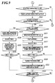
- the slave side print control processing is processing performed when there is a notification that the transfer of image data from the first image forming apparatus 100 which is the master apparatus is complete.
- step S101 judges whether or not the print engine is stopped.
- step S101 When it is judged that the print engine is stopped (step S101: YES), the control section 281 performs the print start notification to the print control section 220a (step S102). Then, the control section 281 waits for the ready notification from the print control section 220a (step S103) and performs the processing of step S104.
- step S101 step S101; NO
- the control section 281 does not perform the processing of step S102 and step S103 and performs the processing of step S104.
- step S104 the control section 281 judges whether or not a later described correction start notification reception flag is ON (step S104).
- the control section 281 transmits the paper feeding instruction to the print control section 220a (step S 105)
- the control section 281 waits for the paper feeding complete notification from the print control section 220a (step S106)
- the control section 281 judges whether or not the paper feeding of the number of sheets to be fed set in the job data is complete (step S 107).
- step S107 When it is judged that the paper feeding of the set number of sheets to be fed is complete (step S107; YES), the control section 281 ends the processing, and when it is judged that the paper feeding of the set number of sheets is not complete (step S 107; NO), the processing of step S104 is performed.
- step S104 when it is judged that the correction start notification reception flag is ON (step S104: YES), the control section 281 reads out the data indicating time (A) from the storage section 282 (step S108).
- the time (A) is a constant number stored in the storage section 282 in a table as shown in FIG 6A , and the time (A) indicates a predicted time from when a stop instruction is transmitted and the print engine stops, the print start notification also performed at this timing and the print engine starts, until when the print engine is in a ready state.
- time (A) is set as 25 seconds, however, any time can be set according to the performance, etc. of the print engine.
- the control section 281 reads out time (B) corresponding to the information indicating a correction type transmitted from the first image forming apparatus 100 from the storage section 282 (step S109).
- the time (B) is a constant number stored in the storage section 282 in a table as shown in FIG 6B
- the time (B) indicates a predicted performing time of correction performed in the first image forming apparatus 100 (master apparatus).
- the types of correction performed in the first image forming apparatus 100 are stabilization A, stabilization B, stabilization C and potential correction, and the predicted performing time of correction is set at 10 seconds, 20 seconds, 60 seconds and 15 seconds respectively.
- the stabilization A for example, toner is not put on the image carrier, and the image carrier is idly run for a predetermined amount of time to remove the noise in a streak which occurs on the image carrier.
- a patch image is formed on the image carrier and the density is measured to perform output adjustment of the laser light source.
- the stabilization C for example, a patch image is formed on the paper, the density of the patch is measured by a density measuring instrument provided in a predetermined position on the conveying path of the paper, and y correction is performed based on the measurement.
- the potential correction the charged amount of the image carrier is measured and the output adjustment of the charging section is performed. Such correction is performed, for example for every predetermined number of pages of image forming.
- the types of correction are not limited to those described above and various types can be employed. In other words, any type can be employed as long as the image forming operation by the image forming section can be stopped, a predetermined adjustment on a predetermined member can be performed, and the image forming operation can be resumed after the adjustment is complete.
- the number of types of correction is not limited to the above described number of four types and can be a number of types other than the above, and can also be one type.
- the control section 281 compares the read out time (A) and time (B), and judges whether or not the time (B) is the time (A) or more (step S110). In other words, the control section 281 judges whether or not it is efficient to stop the print engine while the correction is performed. Here, whether or not to stop the print engine can be judged based on correction type.
- the control section 281 performs stop instruction notification to the print control section 220a (step S111), waits for the correction complete notification from the master apparatus (step S112), and after the correction start notification reception flag is changed to OFF (step S113), the control section 281 performs the processing of step S101.
- the control section 281 does not perform the processing of step S111 and performs the processing of step S112.
- the correction start notification reception occasion (S) processing is an interrupting processing performed when there is a correction start notification indicating start of correction from the first image forming apparatus 100 which is the master apparatus when the slave side print control processing is being performed.
- the control section 281 changes the correction start notification reception flag stored in the RAM 283 to ON and also stores the correction type information indicating the type of correction received with the correction start notification in a predetermined storage area of the RAM 283 (step S201). After performing processing of step S201, the control section 281 ends the processing and returns to the processing of the slave side print control processing before the interruption.
- the master side print control processing is processing performed after performing the transfer complete notification to the second image forming apparatus 200 which is the slave apparatus.
- the control section 181 judges whether or not the print engine is stopped (step S301). When it is judged that the print engine is stopped (step S301: YES), the control section 181 performs the print start notification to the print control section 120a (step S302). Then, the control section 181 waits for the ready notification from the print control section 120a (step S303), and performs the processing of step S304. When it is judged that the print engine is not stopped (step S301; NO), the control section 181 does not perform the processing of step S302 and step S303 and performs the processing of step S304.
- the control section 181 waits for the print request notification from the print control section 120a (step S304) and transmits the print instruction to the print control section 120a (step S305).
- step S306 judges whether or not there is a notification indicating that the sheet is the last sheet with the reception of the print request notification in step S304 (step S306). In other words, the control section 181 judges whether or not it is the print request notification of the last sheet.
- step S306: YES the control section 181 changes the last print instruction flag stored in a predetermined storage area of the RAM 183 to ON (step S307), and performs the processing of step S308.
- step S306: NO the control section 181 does not perform the processing of step S307 and performs the processing of step S308.
- step S308 the control section 181 waits for the print complete notification from the print control section 120a (step S308), and judges whether or not the image forming of the number of pages set in the job data is complete (step S309). In other words, the control section 181 judges whether or not all of the image forming in the job is performed.
- step S309: YES the control section 181 performs a stop instruction notification to the print control section 120a (step S310) and ends the processing.
- step S309: NO the control section 181 judges whether or not the last print instruction flag is ON as shown in FIG 9 (step S311).
- step S311: YES When it is judged that the last print instruction flag is ON (step S311: YES), the control section 181 changes the last print instruction flag stored in the RAM 183 to OFF (step S312). When it is judged that the last print instruction flag is not ON in step S311 (step S311: NO), the control section 181 performs processing of step S304.
- step S313 judges whether or not a later described correction start notification reception flag is ON (step S313).
- step S313: YES the control section 181 judges whether or not a later described time (C) obtainment unnecessary flag is ON (step S314).
- step S313: NO the control section 181 performs the processing of step S304.
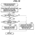
- step S314 when it is judged that the time (C) obtainment unnecessary flag is not ON in step S314 (step S314: NO), the control section 181 obtains the time stamp and this is to be the stop judgment time (Cend) (step S315) and the control section 181 calculates the time (C) which is the difference between the correction notification reception time (Cstart) obtained in a later described correction start notification reception occasion (M) processing, and the obtained stop judgment time (step S316).
- time (C) indicates time from when correction start notification is received from the second image forming apparatus 200 to when there is a print complete notification of the last sheet from the print control section 120a.
- the control section 181 reads out the time (D) from the storage section 182 (step S317).
- the time (D) is a constant number stored in the storage section 182 in a table and indicates a predicted time from when a stop instruction is transmitted and the print engine stops, the print start notification also performed at this timing and the print engine starts, until when the print engine is in a ready state.
- the time (D) is set to 25 seconds similar to the time (A), however, the time can be set freely according to the performance, etc. of the print engine.
- the control section 181 reads out time (B) corresponding to the information indicating a correction type transmitted from the second image forming apparatus 200 from the storage section 182 (step S318).
- the time (B) is a constant number stored in the storage section 182 in a table as shown in FIG 6B
- the time (B) indicates a predicted performing time of correction performed in the second image forming apparatus 200 (slave apparatus).
- the content of each correction and the predicted performing time are similar to those stored in the storage section 282 of the second image forming apparatus 200, and therefore the detailed description is omitted.
- the control section 181 compares the total of the calculated time (C) and time (D) (time (C+D)) with the time (B), and judges whether or not time (B) is the time (C+D) or more (step S319).
- the control section 181 performs stop instruction notification to the print control section 120a (step S320), changes the correction start notification reception flag stored in the RAM 183 to OFF (step S321), waits for the correction complete notification from the slave apparatus (step S322) and performs the processing of step S301.
- step S319: NO the control section 181 does not perform the processing of step S320 and step S321 and performs the processing of step S322.
- step S314 When it is judged that the time (C) obtainment unnecessary flag is ON in step S314 (step S314: YES), the control section 181 changes the time (C) obtainment unnecessary flag stored in the RAM 183 to OFF (step S323), reads out the time (D) and the time (B) corresponding to the correction type (step S324 and step S325), and performs the processing of step S326.
- step S326 the control section 181 compares the read out time (B) and time (D) and judges whether or not the time (B) is the time (D) or more (step S326).
- step S326: YES When it is judged that the time (B) is the time (D) or more (step S326: YES), the control section 181 performs the processing of step S320, and when it is judged that the time (B) is not the time (D) or more (step S326: NO), the processing of step S322 is performed.
- the correction start notification reception occasion (M) processing is an interrupt processing performed when there is a correction start notification from the second image forming apparatus 200 which is the slave apparatus, while the master side print control processing is performed.
- the control section 181 changes the correction start notification reception flag stored in the RAM 183 to ON and stores the correction type information indicating the type of correction received with the correction start notification in a predetermined storage area of the RAM 183 (step S401).
- the control section 181 judges whether or not the last print instruction flag is ON (step S402).
- step S403 the control section 181 judges whether or not the print complete notification is already obtained.
- the print complete notification obtained here is obtained after the print request notification of the last sheet is received, and therefore is the print complete notification of the last sheet.
- step S403: YES the control section 181 changes the time (C) obtainment unnecessary flag stored in a predetermined storage area of the RAM 183 to ON (step S404).
- step S402 NO
- step S403 NO
- the control section 181 changes the time (C) obtainment unnecessary flag to OFF, obtains the time stamp and this is to be a correction notification reception time (Cstart) and the correction notification reception time (Cstart) is stored in the RAM 183 (step S405). With this, it is possible to specify the time when the correction start notification is received.
- control section 181 ends the processing and returns to the processing before interruption in the master side print control processing.
- FIG 11 shows an example of stopping the print engine of the slave apparatus when the correction is in progress in the master apparatus
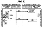
- FIG 12 shows an example of not stopping the print engine of the slave apparatus when the correction is in progress in the master apparatus.
- the print control section 120a of the master apparatus performs a correction start notification to the control section 181 at the timing of starting correction (step C201).
- the processing performed is to be stabilization C.
- the control section 181 transmits the correction start notification to the slave apparatus (step C202).
- the control section 281 of the slave apparatus reads out the time (A) and the time (B) and judges whether or not to stop the print engine as described above.
- the control section 281 of the slave apparatus judges to stop the print engine, and transmits a stop instruction to the print control section 220a (step C203). Then, the print control section 220a discharges the paper A on which the image forming processing is performed to the intermediate buffer apparatus 300 and performs paper discharge notification (step C204). After the discharge of the paper A is complete, the print control section 220a stops the print engine and performs the engine stop complete notification to the control section 281 (step C205).
- the print engine is stopped.
- the time (A) indicates the predicted time of, receiving a correction start notification and transmitting a stop instruction in step C202, completing the discharge of paper in the slave apparatus and stopping the print engine, the control section 281 receiving an engine stop complete notification in step C205 and performing a print start notification at this timing (step C206) and starting the print engine and transmitting a ready notification from the print control section 220a (step C207).
- step C206 and step C207 are virtually performed and not actually performed.
- the intermediate buffer control section 300a when the paper A is received, the intermediate buffer control section 300a performs a paper discharge inquiry to the print control section 120a of the master apparatus (step C208). In this case, since the correction is in progress in the master apparatus and the paper cannot be received, the print control section 120a performs a paper discharge prohibition notification to the intermediate buffer control section 300a (step C209).
- the print control section 120a of the master apparatus performs a correction complete notification to the control section 181 at the timing of completing correction (step C210). Then, the control section 181 of the master apparatus transmits the correction complete notification to the slave apparatus (step C211).
- the control section 281 of the slave apparatus performs a print start notification to the print control section 220a in order to start the stopped print engine (step C212). Then, when the print start notification is received, the print control section 220a starts the print engine, and when the start of the print engine is complete and the print engine is in a state where image forming is possible, the control section 281 performs a ready notification (step C213).
- the control section 281 of the slave apparatus transmits a paper feeding instruction to resume the interrupted job to the print control section 220a (step C214).
- the print control section 220a performs a paper feeding complete notification to the control section 281 (step C215). Then, the slave apparatus continues the job as described above.
- the print control section 120a of the master apparatus After the correction complete notification is transmitted, the print control section 120a of the master apparatus performs a paper discharge authorization notification to the intermediate buffer apparatus 300 (step C216). Then, when the paper discharge authorization notification is received, the intermediate buffer control section 300a sends out the paper A stacked in the buffer section 310 to the first image forming apparatus 100 and also performs a paper discharge notification of the paper A to the print control section 120a of the master apparatus (step C217). Then, the master apparatus continues the job as described above.
- the correction time in the master apparatus is longer than the time until the print engine of the slave apparatus is in a ready state again after the print engine of the slave apparatus is stopped, the deterioration of material and waste of energy of the apparatus occurring due to the apparatus being in a ready state for a long period of time can be suppressed by stopping the print engine and starting after correction is complete.
- the print control section 120a of the master apparatus performs a correction start notification to the control section 181 at the timing of starting the correction (step C301).
- the correction performed is to be stabilization A.
- the control section 181 transmits the correction start notification to the slave apparatus (step C302).
- the control section 281 of the slave apparatus reads out the time (A) and the time (B) and judges whether or not to stop the print engine as described above.
- the control section 281 of the slave apparatus judges not to stop the print engine and waits for a correction complete notification from the master apparatus. Then, the print control section 220a discharges the paper B on which image forming processing is performed to the intermediate buffer apparatus 300 and performs a paper discharge notification (step C303). After the discharge of the paper B is complete, since the stop instruction is not transmitted, the print control section 220a allows the print engine to standby in the ready state.
- the intermediate buffer control section 300a performs a paper discharge inquiry to the print control section 120a of the master apparatus (step C304). In this case, since the correction is in progress in the master apparatus and the paper cannot be received, the print control section 120a performs a paper discharge prohibition notification to the intermediate buffer control section 300a (step C305).
- the print control section 120a of the master apparatus performs a correction complete notification to the control section 181 at the timing of completing correction (step C306). Then, the control section 181 of the master apparatus transmits the correction complete notification to the slave apparatus (step C307).
- the control section 281 of the slave apparatus transmits a paper feeding instruction to resume the interrupted job to the print control section 220a (step C308). After the paper feeding instruction is received and the paper feeding is performed, the print control section 220a performs the paper feeding complete notification to the control section 281 (step C309). Then, the slave apparatus continues the job as described above.
- the print control section 120a of the master apparatus After the correction complete notification is transmitted, the print control section 120a of the master apparatus performs a paper discharge authorization notification to the intermediate buffer apparatus 300 (step C310). Then, when the paper discharge authorization notification is received, the intermediate buffer control section 300a sends out the paper B stacked in the buffer section 310 to the first image forming apparatus 100 and also performs a paper discharge notification of the paper B to the print control section 120a of the master apparatus (step C311). Then, the master apparatus continues the job as described above.
- the interrupted job can be speedily resumed after correction and productivity is enhanced by maintaining the print engine in a ready state.
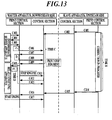
- FIG 13 shows an example of stopping the print engine of the master apparatus after the master apparatus performs the processing on the paper on which the image forming is performed by the slave apparatus when the correction is in progress in the slave apparatus
- FIG 14 shows an example of stopping the print engine of the master apparatus when the correction is in progress in the slave apparatus and the correction in the slave apparatus is started after the print complete notification of the last sheet is received in the master apparatus
- FIG 15 shows an example of not stopping the print engine of the master apparatus after the master apparatus performs the processing on the paper on which the image forming is performed by the slave apparatus when the correction is in progress in the slave apparatus.
- the print control section 220a of the slave apparatus performs a correction start notification to the control section 281 at the timing of starting the correction (step C401).
- the correction performed is to be stabilization C.
- the correction section 281 transmits the correction start notification to the master apparatus (step C402).
- the control section 181 of the master apparatus obtains the correction notification reception time (Cstart) and waits for the print request notification from the print control section 120a.
- the intermediate buffer control section 300a performs a paper discharge inquiry notification to the print control section 120a of the master apparatus (step C403).
- the print control section 120a of the master apparatus performs a paper discharge authorization notification to the intermediate buffer control section 300a (step C404).
- the intermediate buffer control section 300a sends out the paper C stacked in the buffer section 310 to the master apparatus and also performs a paper discharge notification of the paper C to the print control section 120a of the master apparatus (step C405). Together with the paper discharge notification, a notification indicating the last sheet is also performed.
- the print control section 120a of the master apparatus When the paper C is conveyed from the intermediate buffer apparatus 300, the print control section 120a of the master apparatus performs a print request notification for the paper C to the control section 181 (step C406). Together with the print request notification, a notification indicating the last sheet is also performed.
- the control section 181 of the master apparatus transmits a print instruction to the print control section 120a to perform the image forming on the paper C (step C407).
- the print control section 120a allows the image forming section 121 to perform the image forming on the paper C.
- the paper C after the image is formed is to be paper D.
- the print control section 120a performs a print complete notification to the control section 181 (step C408).
- the control section 181 of the master apparatus obtains the stop judgment time (Cend) and calculates the time (C) and also reads out the time (B) and the time (D). The control section 181 judges whether or not to stop the print engine based on the above.
- the control section 181 of the master apparatus judges to stop the print engine and transmits a stop instruction to the print control section 120a (step C409). Then, the print control section 120a discharges the paper D to the relay conveying apparatus 500 (step C410), stops the print engine at the timing when the post processing by the post processing apparatus 600 is complete, and performs engine stop complete notification to the control section 181 (step C411).
- the print engine is stopped after the post processing of all of the sheets of paper is complete.
- the time (D) indicates the predicted time of, receiving a print complete notification of the last sheet in step C408 and transmitting a stop instruction, completing post processing on the paper processed in the master apparatus and stopping the print engine, the control section 181 receiving the engine stop complete notification in step C411 and performing a print start notification at this timing (step C412), and starting the print engine and transmitting a ready notification from the print control section 120a (step C413).
- step C412 and step C413 are virtually performed and not actually performed.
- the print control section 220a of the slave apparatus performs a correction complete notification to the control section 281 at the timing of completing correction (step C414).
- the correction section 281 of the slave apparatus transmits the correction complete notification to the master apparatus (step C415).
- the slave apparatus resumes the interrupted job and continues to perform the resumed job as described above.
- the control section 181 of the master apparatus performs a print start notification to the print control section 120a in order to start the stopped print engine (step C416). Then, when the print start notification is received, the print control section 120a starts the print engine, and when the start of the print engine is complete and the print engine is in a state where image forming is possible, the print control section 120a performs a ready notification to the control section 181 (step S417). Then, the master apparatus resumes the interrupted job and continues to perform the resumed job as described above.
- the correction time of the slave apparatus is longer than the time until the print complete notification of the last sheet after receiving the correction start notification of the master apparatus (in other words, the time until performing judgment of whether or not to stop the print engine after correction start notification) and the time until the print engine is in a ready state again after stopping the print engine, the deterioration of material and waste of energy of the apparatus occurring due to the apparatus being in a ready state for a long period of time can be suppressed by stopping the print engine and starting after correction is complete.
- the print control section 220a of the slave apparatus performs a correction start notification to the control section 281 at the timing of starting correction (step C501).
- the correction performed is to be stabilization C.
- the control section 281 transmits a correction start notification to the master apparatus (step C502). Since the print complete notification of the last sheet is received from the print control section 120a before receiving the correction start notification (step C503), at the timing of receiving the correction start notification, the control section 181 of the master apparatus reads out the time (B) and the time (D) and judges whether or not to stop the print engine.
- the control section 181 of the master apparatus judges to stop the print engine and transmits a stop instruction to the print control section 120a (step C504). Then, the print control section 120a discharges paper E on which image forming processing in the master apparatus is complete to the relay conveying apparatus 500 (step C505), stops the print engine at the timing that the post processing by the post processing apparatus 600 is complete, and performs an engine stop complete notification to the control section 181 (step C506).
- the time (D) indicates the predicted time of, receiving a correction start notification in step C502, transmitting the stop instruction based on the stop judgment of the print engine, completing the post processing on the paper processed in the master apparatus and stopping the print engine, the control section 181 receiving an engine stop complete notification in step C506 and at this timing performing a print start notification (step C507), and starting the print engine and transmitting a ready notification from the print control section 120a (step C508).
- step C507 and step C508 are virtually performed, and are not actually performed.
- the print control section 220a of the slave apparatus performs a correction complete notification to the control section 281 at the timing of completing correction (step C509). Then, the control section 281 of the slave apparatus transmits the correction complete notification to the master apparatus (step C510). Then, the slave apparatus resumes the interrupted job and continues to perform the resumed job as described above.
- the control section 181 of the master apparatus performs a print start notification to the print control section 120a in order to start the stopped print engine (step C511). Then, when the print start notification is received, the print control section 120a starts the print engine and when the start of the print engine is complete and the print engine is in a state where image forming is possible, the print control section 120a performs a ready notification to the control section 181 (step S512). Then, the master apparatus resumes the interrupted job and continues to perform the resumed job as described above.
- the correction time of the slave apparatus is longer than the time until the print engine is in a ready state again after the print engine is stopped, the deterioration of material and waste of energy of the apparatus occurring due to the apparatus being in a ready state for a long period of time can be suppressed by stopping the print engine and starting after correction is complete.
- the print control section 220a of the slave apparatus performs a correction start notification to the control section 281 at the timing of starting correction (step C601).
- the correction performed is to be stabilization B.
- the control section 281 transmits the correction start notification to the master apparatus (step C602).
- the control section 181 of the master apparatus obtains the correction notification reception time (Cstart) and waits for the print request notification from the print control section 120a.
- the intermediate buffer control section 300a performs a paper discharge inquiry notification to the print control section 120a of the master apparatus (step C603).
- the print control section 120a of the master apparatus performs a paper discharge authorization notification to the intermediate buffer control section 300a (step C604).
- the intermediate buffer control section 300a sends out the paper F stacked in the buffer section 310 to the master apparatus and also performs a paper discharge notification of the paper F to the print control section 120a of the master apparatus (step S605). Together with the paper discharge notification, a notification indicating that the paper is the last sheet is also performed.
- the print control section 120a of the master apparatus When the paper F is conveyed from the intermediate buffer apparatus 300, the print control section 120a of the master apparatus performs a print request notification of the paper F to the control section 181 (step C606). Together with the print request notification, a notification indicating that the paper is the last sheet is also performed.
- the control section 181 of the master apparatus transmits a print instruction to the print control section 120a to perform image forming on the paper F (step C607).
- the print control section 120a allows the image forming section 121 to perform image forming on the paper F.
- the paper F after the image is formed is to be paper G
- the print control section 120a performs a print complete notification to the control section 181 (step C608).
- the control section 181 of the master apparatus obtains the stop judgment time (Cend) and calculates the time (C) and also reads out the time (B) and the time (D). The control section 181 judges whether or not to stop the print engine based on the above.
- the control section 181 of the master apparatus judges not to stop the print engine and waits for the correction complete notification from the slave apparatus. Then, the print control section 120a discharges the paper G on which image forming processing is complete to the relay conveying apparatus 500 (step C609). After the discharge of the paper G is complete, since the stop instruction is not transmitted, the print control section 120a allows the print engine to standby in a ready state.
- the print control section 220a of the slave apparatus performs a correction complete notification to the control section 281 (step C610). Then, the control section 281 of the slave apparatus transmits the correction complete notification to the master apparatus (step C611). Then, the slave apparatus resumes the interrupted job and continues to perform the resumed job as described above.
- control section 181 of the master apparatus resumes the interrupted job and continues to perform the resumed job as described above.
- a first image forming apparatus 100 and a second image forming apparatus 200 each including image forming sections 121 and 221, and control sections 181 and 281, respectively.
- the image forming sections 121 and 221 form an image on paper.
- the control sections 181 and 281 stop the image forming operation by the image forming sections 121 and 221, perform predetermined adjustment, resumes the image forming operation by the image forming sections 181 and 281 after the adjustment is complete, and performs notification that adjustment is performed to the other image forming apparatus among the first image forming apparatus 100 and the second image forming apparatus 200 when the adjustment is performed.
- control sections 181 and 281 stop the driving of the image forming sections 121 and 221 when the adjustment is in progress in the other image forming apparatus and put the image forming sections 121 and 221 in a driving stopped state.
- any one of the plurality of image forming apparatuses while an adjustment in which the image forming operation cannot be continuously performed is in progress, the image forming section of the other image forming apparatus is in a driving stopped state, idle driving is not performed for a long period of time and the deterioration of material and waste of energy of the apparatus in the image forming apparatus can be suppressed and is therefore efficient.
- the control sections 181 and 281 of the first image forming apparatus 100 and the second image forming apparatus 200 each specify time necessary for adjustment.
- the control sections 181 and 281 do not stop the driving of the image forming sections 121 and 221 and put the image forming sections 121 and 221 on standby in a ready state until the adjustment is complete.
- control sections 181 and 281 of the first image forming apparatus 100 and the second image forming apparatus 200 can each perform a plurality of types of adjustment.
- the control sections 181 and 281 perform notification that adjustment is performed to the other image forming apparatus so that it is possible to specify the type of adjustment.
- the control sections 181 and 281 specify the time necessary for adjustment from the type of judgment specified in the notification.
- the control section 181 of the first image forming apparatus 100 provided in a downstream side puts the image forming section 121 on standby in the ready state.
- the control section 281 of the second image forming apparatus 200 provided in the upstream side puts the image forming section 221 on standby in the ready state.
- each of the control sections 181 and 281 of the first image forming apparatus 100 and the second image forming apparatus 200 is able to perform a plurality of types of adjustment.
- the control sections 181 and 281 perform the notification that the adjustment is performed to the other image forming apparatus so that it is possible to specify the type of the adjustment.
- the control sections 181 and 281 judge whether or not to put the image forming sections 121 and 221 in the driving stopped state based on the type of adjustment specified by the notification.
- the control sections 181 and 281 put the image forming sections 121 and 221 in the driving stopped state.
- control section 181 and 281 do not stop the driving of the image forming sections 121 and 221, and the image forming sections 121 and 221 are put on standby in the ready state until the adjustment is complete.
- the intermediate buffer apparatus 300 is provided between the first image forming apparatus 100 and the second image forming apparatus 200.
- the intermediate buffer apparatus 300 receives and accumulates paper discharged from the second image forming apparatus 200 provided in an upstream side of a paper conveying direction.
- the intermediate buffer apparatus 300 sends out the accumulated paper to the image forming apparatus 100 provided in a downstream side.
- the control sections 181 and 281 of the first image forming apparatus 100 and the second image forming apparatus 200 each discharges the paper on which image forming processing is performed by the image forming sections 121 and 221 outside the apparatus, and then puts the image forming sections 121 and 221 in the driving stopped state.
- the description of the embodiment of the present invention is one example of the image forming system of the present invention and is not limited to the above.
- the specific configuration and the specific operation of each functional section composing the image forming system can be suitably modified.
- the image forming apparatus positioned in the upstream side is the slave apparatus and the image forming apparatus positioned in the downstream side is the master apparatus, however, the image forming apparatus positioned in the upstream side can be the master apparatus and the image forming apparatus positioned in the downstream side can be the slave apparatus.
- the image forming system of the present embodiment is composed of two image forming apparatuses, however, the image forming system can be composed of three or more image forming apparatuses.
- an intermediate buffer apparatus is provided, and the paper on which image forming processing is performed by the image forming apparatus provided in the upstream side can be accumulated, however, a mechanism of accumulating the paper in any one of the plurality of image forming apparatuses can be provided and the paper can be accumulated by such mechanism instead of providing an intermediate buffer apparatus.
- the driving of the print engine when the performing time of the correction is shorter than the time of stopping driving of the print engine, starting the print engine and becoming the ready state, the driving of the print engine is not stopped, however, the driving of the print engine can be stopped regardless of the performing time of the correction.
- the correction complete notification is transmitted to the image forming apparatus of the upstream side at the timing of completing the correction, however, the time for starting the print engine can be considered, and control can be performed so that the correction complete notification is transmitted at a predetermined time before the correction is complete, and the correction is complete when the start of the print engine is complete. With this, the productivity can be enhanced even more.
- the driving of the print engine of one image forming apparatus is stopped when the correction in the other image forming apparatus is performed, however, when the driving of an optional apparatus such as a post processing apparatus, etc. is controlled together with any of the plurality of the image forming apparatuses, the driving of the print engine of the one image forming apparatus can be stopped when the correction is performed in the optional apparatus.
- a computer readable medium including a program of the present invention an example using a hard disk or a nonvolatile semiconductor memory is disclosed, however it is not limited to this example.
- a portable recording medium such as a CD-ROM, etc. can be applied.
- a carrier wave can also be applied.
Landscapes
- Physics & Mathematics (AREA)
- General Physics & Mathematics (AREA)
- Control Or Security For Electrophotography (AREA)
- Facsimiles In General (AREA)
- Accessory Devices And Overall Control Thereof (AREA)
Applications Claiming Priority (1)
| Application Number | Priority Date | Filing Date | Title |
|---|---|---|---|
| JP2010201505A JP5585326B2 (ja) | 2010-09-09 | 2010-09-09 | 画像形成システム |
Publications (3)
| Publication Number | Publication Date |
|---|---|
| EP2428845A2 true EP2428845A2 (de) | 2012-03-14 |
| EP2428845A3 EP2428845A3 (de) | 2015-03-25 |
| EP2428845B1 EP2428845B1 (de) | 2020-03-18 |
Family
ID=44763833
Family Applications (1)
| Application Number | Title | Priority Date | Filing Date |
|---|---|---|---|
| EP11178618.2A Active EP2428845B1 (de) | 2010-09-09 | 2011-08-24 | Bilderzeugendes System |
Country Status (3)
| Country | Link |
|---|---|
| US (1) | US8493589B2 (de) |
| EP (1) | EP2428845B1 (de) |
| JP (1) | JP5585326B2 (de) |
Families Citing this family (11)
| Publication number | Priority date | Publication date | Assignee | Title |
|---|---|---|---|---|
| JP5822734B2 (ja) * | 2012-01-16 | 2015-11-24 | シャープ株式会社 | 中継搬送装置および印刷システム |
| JP5900093B2 (ja) * | 2012-03-28 | 2016-04-06 | コニカミノルタ株式会社 | 画像形成システム、画像形成システムの制御方法及び画像形成システムを制御するプログラム |
| JP6003159B2 (ja) * | 2012-04-02 | 2016-10-05 | コニカミノルタ株式会社 | 画像形成システム |
| JP6186857B2 (ja) * | 2013-05-01 | 2017-08-30 | コニカミノルタ株式会社 | 画像形成システム |
| JP6070949B2 (ja) * | 2013-11-07 | 2017-02-01 | コニカミノルタ株式会社 | 画像形成装置および画像形成システム |
| US9250594B2 (en) * | 2014-02-24 | 2016-02-02 | Xerox Corporation | Systems and methods for implementing an asynchronous buffering module with an integrated registration function for inline printing an image forming system |
| JP6217681B2 (ja) * | 2015-03-26 | 2017-10-25 | コニカミノルタ株式会社 | 画像形成システム及び画像形成方法 |
| JP2017116720A (ja) * | 2015-12-24 | 2017-06-29 | キヤノン株式会社 | 画像形成装置 |
| JP6497356B2 (ja) * | 2016-05-20 | 2019-04-10 | 京セラドキュメントソリューションズ株式会社 | 画像形成装置及び画像形成装置の制御方法 |
| JP7172225B2 (ja) * | 2018-07-20 | 2022-11-16 | 富士フイルムビジネスイノベーション株式会社 | 画像形成システム |
| JP7363386B2 (ja) * | 2019-11-07 | 2023-10-18 | 富士フイルムビジネスイノベーション株式会社 | 画像形成装置、プログラム |
Citations (1)
| Publication number | Priority date | Publication date | Assignee | Title |
|---|---|---|---|---|
| JPH07237336A (ja) | 1994-01-10 | 1995-09-12 | Fujitsu Ltd | 連続紙の両面印刷システム |
Family Cites Families (20)
| Publication number | Priority date | Publication date | Assignee | Title |
|---|---|---|---|---|
| JPS59121066A (ja) * | 1982-12-28 | 1984-07-12 | Canon Inc | 画像記録装置 |
| JPS59121064A (ja) * | 1982-12-28 | 1984-07-12 | Canon Inc | 画像記録装置 |
| JP3824037B2 (ja) * | 1998-03-06 | 2006-09-20 | リコープリンティングシステムズ株式会社 | 電子写真印刷装置の転写制御方法 |
| JP2002086831A (ja) * | 2000-09-08 | 2002-03-26 | Fujitsu Ltd | 印刷システム |
| JP2002229278A (ja) * | 2001-01-30 | 2002-08-14 | Canon Inc | キャリブレーション方法、印刷装置および画像処理装置 |
| JP3793055B2 (ja) * | 2001-08-01 | 2006-07-05 | キヤノン株式会社 | 画像形成システム及び画像形成装置、及びその制御方法 |
| JP2003319112A (ja) * | 2002-04-24 | 2003-11-07 | Ricoh Co Ltd | 画像形成装置 |
| JP4487581B2 (ja) * | 2003-02-21 | 2010-06-23 | 富士ゼロックス株式会社 | 重連印刷装置および重連印刷方法 |
| JP2005080260A (ja) * | 2003-09-04 | 2005-03-24 | Ricoh Co Ltd | 画像形成システム及び画像形成装置 |
| JP2005329594A (ja) * | 2004-05-19 | 2005-12-02 | Ricoh Co Ltd | 画像形成システム及び画像形成装置 |
| JP2006116742A (ja) * | 2004-10-19 | 2006-05-11 | Canon Inc | 画像形成装置およびその制御方法 |
| JP2006224465A (ja) * | 2005-02-17 | 2006-08-31 | Kyocera Mita Corp | 画像形成装置、画像形成装置におけるキャリブレーション処理方法および画像形成装置におけるキャリブレーション処理プログラム |
| JP2008044206A (ja) * | 2006-08-14 | 2008-02-28 | Fuji Xerox Co Ltd | 印刷システム及び印刷装置の制御方法 |
| JP4735850B2 (ja) * | 2006-11-28 | 2011-07-27 | 富士ゼロックス株式会社 | 消耗品管理装置、画像形成装置及びプログラム |
| JP4850150B2 (ja) * | 2007-08-27 | 2012-01-11 | 株式会社リコー | タンデム式連続紙印刷装置およびそのエラーリカバリ方法 |
| JP2009300703A (ja) * | 2008-06-13 | 2009-12-24 | Ricoh Co Ltd | 印刷装置 |
| JP5623012B2 (ja) * | 2008-08-29 | 2014-11-12 | キヤノン株式会社 | 印刷システム、制御方法およびプログラム |
| JP5282303B2 (ja) * | 2008-12-22 | 2013-09-04 | コニカミノルタ株式会社 | 画像形成装置 |
| JP2011128464A (ja) * | 2009-12-18 | 2011-06-30 | Canon Inc | 画像形成システム |
| US9274914B2 (en) * | 2010-07-22 | 2016-03-01 | Hewlett-Packard Development Company, L.P. | System and method for presenting alert notifications for master and slave devices if in idle operational states |
-
2010
- 2010-09-09 JP JP2010201505A patent/JP5585326B2/ja not_active Expired - Fee Related
-
2011
- 2011-08-24 EP EP11178618.2A patent/EP2428845B1/de active Active
- 2011-09-06 US US13/225,736 patent/US8493589B2/en active Active
Patent Citations (1)
| Publication number | Priority date | Publication date | Assignee | Title |
|---|---|---|---|---|
| JPH07237336A (ja) | 1994-01-10 | 1995-09-12 | Fujitsu Ltd | 連続紙の両面印刷システム |
Also Published As
| Publication number | Publication date |
|---|---|
| JP2012058487A (ja) | 2012-03-22 |
| US8493589B2 (en) | 2013-07-23 |
| EP2428845B1 (de) | 2020-03-18 |
| JP5585326B2 (ja) | 2014-09-10 |
| US20120062925A1 (en) | 2012-03-15 |
| EP2428845A3 (de) | 2015-03-25 |
Similar Documents
| Publication | Publication Date | Title |
|---|---|---|
| EP2428845B1 (de) | Bilderzeugendes System | |
| RU2501059C2 (ru) | Печатающее устройство, допускающее предотвращение ошибки подачи листов при очистке, способ управления печатающим устройством и носитель данных | |
| JP6340920B2 (ja) | 画像形成システムおよび画像形成方法 | |
| CN105313498B (zh) | 图像形成装置以及图像印刷方法 | |
| CN107145046B (zh) | 图像形成装置、图像形成方法以及图像形成管理装置 | |
| US20120287450A1 (en) | Image forming apparatus | |
| CN107145045B (zh) | 图像形成装置、图像形成管理装置以及图像形成方法 | |
| US7684722B2 (en) | Image forming apparatus having a comparing unit and a controlling unit | |
| JP2015013452A (ja) | 画像形成装置および画像形成システム | |
| JP6642248B2 (ja) | 画像形成装置、画像形成システムおよび報知方法 | |
| EP3179311A1 (de) | Bilderzeugungsvorrichtung, bilderzeugungssystem und aufzeichnungsmedium | |
| CN106483803A (zh) | 图像形成系统、图像形成装置以及转印条件改变方法 | |
| US8619311B2 (en) | Image reading apparatus and a method for controlling the same to perform print processing based on the stored image data | |
| JP2020095135A (ja) | 画像形成装置 | |
| US20100067047A1 (en) | Display control apparatus, image forming apparatus, and computer-readable medium storing display control program | |
| JP7009895B2 (ja) | 画像形成装置及び画像形成装置において実行される方法 | |
| JP2009237121A (ja) | 画像形成装置、画像形成装置の制御方法、プログラム、及び記録媒体 | |
| CN103428395A (zh) | 环境负荷显示处理装置、环境负荷显示方法 | |
| JP2001356647A (ja) | 画像形成装置 | |
| JP5293619B2 (ja) | 画像形成装置 | |
| JP2004262078A (ja) | 画像形成装置 | |
| US20120093536A1 (en) | Image forming system | |
| JP2004345252A (ja) | 画像形成装置および画像形成方法 | |
| JP2014095881A (ja) | 画像形成装置 | |
| JP2005173040A (ja) | 画像形成装置及び画像形成方法 |
Legal Events
| Date | Code | Title | Description |
|---|---|---|---|
| AK | Designated contracting states |
Kind code of ref document: A2 Designated state(s): AL AT BE BG CH CY CZ DE DK EE ES FI FR GB GR HR HU IE IS IT LI LT LU LV MC MK MT NL NO PL PT RO RS SE SI SK SM TR |
|
| AX | Request for extension of the european patent |
Extension state: BA ME |
|
| PUAI | Public reference made under article 153(3) epc to a published international application that has entered the european phase |
Free format text: ORIGINAL CODE: 0009012 |
|
| PUAL | Search report despatched |
Free format text: ORIGINAL CODE: 0009013 |
|
| AK | Designated contracting states |
Kind code of ref document: A3 Designated state(s): AL AT BE BG CH CY CZ DE DK EE ES FI FR GB GR HR HU IE IS IT LI LT LU LV MC MK MT NL NO PL PT RO RS SE SI SK SM TR |
|
| AX | Request for extension of the european patent |
Extension state: BA ME |
|
| RIC1 | Information provided on ipc code assigned before grant |
Ipc: G03G 21/14 20060101ALI20150218BHEP Ipc: G03G 15/00 20060101AFI20150218BHEP Ipc: G03G 15/23 20060101ALI20150218BHEP |
|
| 17P | Request for examination filed |
Effective date: 20150925 |
|
| RBV | Designated contracting states (corrected) |
Designated state(s): AL AT BE BG CH CY CZ DE DK EE ES FI FR GB GR HR HU IE IS IT LI LT LU LV MC MK MT NL NO PL PT RO RS SE SI SK SM TR |
|
| RIC1 | Information provided on ipc code assigned before grant |
Ipc: G03G 15/00 20060101AFI20190808BHEP Ipc: G03G 15/23 20060101ALI20190808BHEP Ipc: G03G 21/14 20060101ALI20190808BHEP |
|
| GRAP | Despatch of communication of intention to grant a patent |
Free format text: ORIGINAL CODE: EPIDOSNIGR1 |
|
| STAA | Information on the status of an ep patent application or granted ep patent |
Free format text: STATUS: GRANT OF PATENT IS INTENDED |
|
| INTG | Intention to grant announced |
Effective date: 20191014 |
|
| GRAS | Grant fee paid |
Free format text: ORIGINAL CODE: EPIDOSNIGR3 |
|
| GRAA | (expected) grant |
Free format text: ORIGINAL CODE: 0009210 |
|
| STAA | Information on the status of an ep patent application or granted ep patent |
Free format text: STATUS: THE PATENT HAS BEEN GRANTED |
|
| AK | Designated contracting states |
Kind code of ref document: B1 Designated state(s): AL AT BE BG CH CY CZ DE DK EE ES FI FR GB GR HR HU IE IS IT LI LT LU LV MC MK MT NL NO PL PT RO RS SE SI SK SM TR |
|
| REG | Reference to a national code |
Ref country code: GB Ref legal event code: FG4D |
|
| REG | Reference to a national code |
Ref country code: DE Ref legal event code: R096 Ref document number: 602011065637 Country of ref document: DE |
|
| REG | Reference to a national code |
Ref country code: AT Ref legal event code: REF Ref document number: 1246610 Country of ref document: AT Kind code of ref document: T Effective date: 20200415 Ref country code: IE Ref legal event code: FG4D |
|
| PG25 | Lapsed in a contracting state [announced via postgrant information from national office to epo] |
Ref country code: RS Free format text: LAPSE BECAUSE OF FAILURE TO SUBMIT A TRANSLATION OF THE DESCRIPTION OR TO PAY THE FEE WITHIN THE PRESCRIBED TIME-LIMIT Effective date: 20200318 Ref country code: NO Free format text: LAPSE BECAUSE OF FAILURE TO SUBMIT A TRANSLATION OF THE DESCRIPTION OR TO PAY THE FEE WITHIN THE PRESCRIBED TIME-LIMIT Effective date: 20200618 Ref country code: FI Free format text: LAPSE BECAUSE OF FAILURE TO SUBMIT A TRANSLATION OF THE DESCRIPTION OR TO PAY THE FEE WITHIN THE PRESCRIBED TIME-LIMIT Effective date: 20200318 |
|
| REG | Reference to a national code |
Ref country code: NL Ref legal event code: MP Effective date: 20200318 |
|
| PG25 | Lapsed in a contracting state [announced via postgrant information from national office to epo] |
Ref country code: LV Free format text: LAPSE BECAUSE OF FAILURE TO SUBMIT A TRANSLATION OF THE DESCRIPTION OR TO PAY THE FEE WITHIN THE PRESCRIBED TIME-LIMIT Effective date: 20200318 Ref country code: SE Free format text: LAPSE BECAUSE OF FAILURE TO SUBMIT A TRANSLATION OF THE DESCRIPTION OR TO PAY THE FEE WITHIN THE PRESCRIBED TIME-LIMIT Effective date: 20200318 Ref country code: HR Free format text: LAPSE BECAUSE OF FAILURE TO SUBMIT A TRANSLATION OF THE DESCRIPTION OR TO PAY THE FEE WITHIN THE PRESCRIBED TIME-LIMIT Effective date: 20200318 Ref country code: BG Free format text: LAPSE BECAUSE OF FAILURE TO SUBMIT A TRANSLATION OF THE DESCRIPTION OR TO PAY THE FEE WITHIN THE PRESCRIBED TIME-LIMIT Effective date: 20200618 Ref country code: GR Free format text: LAPSE BECAUSE OF FAILURE TO SUBMIT A TRANSLATION OF THE DESCRIPTION OR TO PAY THE FEE WITHIN THE PRESCRIBED TIME-LIMIT Effective date: 20200619 |
|
| REG | Reference to a national code |
Ref country code: LT Ref legal event code: MG4D |
|
| PG25 | Lapsed in a contracting state [announced via postgrant information from national office to epo] |
Ref country code: NL Free format text: LAPSE BECAUSE OF FAILURE TO SUBMIT A TRANSLATION OF THE DESCRIPTION OR TO PAY THE FEE WITHIN THE PRESCRIBED TIME-LIMIT Effective date: 20200318 |
|
| PG25 | Lapsed in a contracting state [announced via postgrant information from national office to epo] |
Ref country code: SK Free format text: LAPSE BECAUSE OF FAILURE TO SUBMIT A TRANSLATION OF THE DESCRIPTION OR TO PAY THE FEE WITHIN THE PRESCRIBED TIME-LIMIT Effective date: 20200318 Ref country code: IS Free format text: LAPSE BECAUSE OF FAILURE TO SUBMIT A TRANSLATION OF THE DESCRIPTION OR TO PAY THE FEE WITHIN THE PRESCRIBED TIME-LIMIT Effective date: 20200718 Ref country code: CZ Free format text: LAPSE BECAUSE OF FAILURE TO SUBMIT A TRANSLATION OF THE DESCRIPTION OR TO PAY THE FEE WITHIN THE PRESCRIBED TIME-LIMIT Effective date: 20200318 Ref country code: EE Free format text: LAPSE BECAUSE OF FAILURE TO SUBMIT A TRANSLATION OF THE DESCRIPTION OR TO PAY THE FEE WITHIN THE PRESCRIBED TIME-LIMIT Effective date: 20200318 Ref country code: SM Free format text: LAPSE BECAUSE OF FAILURE TO SUBMIT A TRANSLATION OF THE DESCRIPTION OR TO PAY THE FEE WITHIN THE PRESCRIBED TIME-LIMIT Effective date: 20200318 Ref country code: PT Free format text: LAPSE BECAUSE OF FAILURE TO SUBMIT A TRANSLATION OF THE DESCRIPTION OR TO PAY THE FEE WITHIN THE PRESCRIBED TIME-LIMIT Effective date: 20200812 Ref country code: RO Free format text: LAPSE BECAUSE OF FAILURE TO SUBMIT A TRANSLATION OF THE DESCRIPTION OR TO PAY THE FEE WITHIN THE PRESCRIBED TIME-LIMIT Effective date: 20200318 Ref country code: LT Free format text: LAPSE BECAUSE OF FAILURE TO SUBMIT A TRANSLATION OF THE DESCRIPTION OR TO PAY THE FEE WITHIN THE PRESCRIBED TIME-LIMIT Effective date: 20200318 |
|
| REG | Reference to a national code |
Ref country code: AT Ref legal event code: MK05 Ref document number: 1246610 Country of ref document: AT Kind code of ref document: T Effective date: 20200318 |
|
| REG | Reference to a national code |
Ref country code: DE Ref legal event code: R097 Ref document number: 602011065637 Country of ref document: DE |
|
| PLBE | No opposition filed within time limit |
Free format text: ORIGINAL CODE: 0009261 |
|
| STAA | Information on the status of an ep patent application or granted ep patent |
Free format text: STATUS: NO OPPOSITION FILED WITHIN TIME LIMIT |
|
| PG25 | Lapsed in a contracting state [announced via postgrant information from national office to epo] |
Ref country code: DK Free format text: LAPSE BECAUSE OF FAILURE TO SUBMIT A TRANSLATION OF THE DESCRIPTION OR TO PAY THE FEE WITHIN THE PRESCRIBED TIME-LIMIT Effective date: 20200318 Ref country code: AT Free format text: LAPSE BECAUSE OF FAILURE TO SUBMIT A TRANSLATION OF THE DESCRIPTION OR TO PAY THE FEE WITHIN THE PRESCRIBED TIME-LIMIT Effective date: 20200318 Ref country code: IT Free format text: LAPSE BECAUSE OF FAILURE TO SUBMIT A TRANSLATION OF THE DESCRIPTION OR TO PAY THE FEE WITHIN THE PRESCRIBED TIME-LIMIT Effective date: 20200318 Ref country code: ES Free format text: LAPSE BECAUSE OF FAILURE TO SUBMIT A TRANSLATION OF THE DESCRIPTION OR TO PAY THE FEE WITHIN THE PRESCRIBED TIME-LIMIT Effective date: 20200318 |
|
| 26N | No opposition filed |
Effective date: 20201221 |
|
| PG25 | Lapsed in a contracting state [announced via postgrant information from national office to epo] |
Ref country code: PL Free format text: LAPSE BECAUSE OF FAILURE TO SUBMIT A TRANSLATION OF THE DESCRIPTION OR TO PAY THE FEE WITHIN THE PRESCRIBED TIME-LIMIT Effective date: 20200318 |
|
| PG25 | Lapsed in a contracting state [announced via postgrant information from national office to epo] |
Ref country code: MC Free format text: LAPSE BECAUSE OF FAILURE TO SUBMIT A TRANSLATION OF THE DESCRIPTION OR TO PAY THE FEE WITHIN THE PRESCRIBED TIME-LIMIT Effective date: 20200318 |
|
| REG | Reference to a national code |
Ref country code: CH Ref legal event code: PL |
|
| PG25 | Lapsed in a contracting state [announced via postgrant information from national office to epo] |
Ref country code: LU Free format text: LAPSE BECAUSE OF NON-PAYMENT OF DUE FEES Effective date: 20200824 Ref country code: CH Free format text: LAPSE BECAUSE OF NON-PAYMENT OF DUE FEES Effective date: 20200831 Ref country code: LI Free format text: LAPSE BECAUSE OF NON-PAYMENT OF DUE FEES Effective date: 20200831 |
|
| REG | Reference to a national code |
Ref country code: BE Ref legal event code: MM Effective date: 20200831 |
|
| PG25 | Lapsed in a contracting state [announced via postgrant information from national office to epo] |
Ref country code: SI Free format text: LAPSE BECAUSE OF FAILURE TO SUBMIT A TRANSLATION OF THE DESCRIPTION OR TO PAY THE FEE WITHIN THE PRESCRIBED TIME-LIMIT Effective date: 20200318 |
|
| PG25 | Lapsed in a contracting state [announced via postgrant information from national office to epo] |
Ref country code: IE Free format text: LAPSE BECAUSE OF NON-PAYMENT OF DUE FEES Effective date: 20200824 Ref country code: BE Free format text: LAPSE BECAUSE OF NON-PAYMENT OF DUE FEES Effective date: 20200831 |
|
| PG25 | Lapsed in a contracting state [announced via postgrant information from national office to epo] |
Ref country code: TR Free format text: LAPSE BECAUSE OF FAILURE TO SUBMIT A TRANSLATION OF THE DESCRIPTION OR TO PAY THE FEE WITHIN THE PRESCRIBED TIME-LIMIT Effective date: 20200318 Ref country code: MT Free format text: LAPSE BECAUSE OF FAILURE TO SUBMIT A TRANSLATION OF THE DESCRIPTION OR TO PAY THE FEE WITHIN THE PRESCRIBED TIME-LIMIT Effective date: 20200318 Ref country code: CY Free format text: LAPSE BECAUSE OF FAILURE TO SUBMIT A TRANSLATION OF THE DESCRIPTION OR TO PAY THE FEE WITHIN THE PRESCRIBED TIME-LIMIT Effective date: 20200318 |
|
| PG25 | Lapsed in a contracting state [announced via postgrant information from national office to epo] |
Ref country code: MK Free format text: LAPSE BECAUSE OF FAILURE TO SUBMIT A TRANSLATION OF THE DESCRIPTION OR TO PAY THE FEE WITHIN THE PRESCRIBED TIME-LIMIT Effective date: 20200318 Ref country code: AL Free format text: LAPSE BECAUSE OF FAILURE TO SUBMIT A TRANSLATION OF THE DESCRIPTION OR TO PAY THE FEE WITHIN THE PRESCRIBED TIME-LIMIT Effective date: 20200318 |
|
| P01 | Opt-out of the competence of the unified patent court (upc) registered |
Effective date: 20230510 |
|
| PGFP | Annual fee paid to national office [announced via postgrant information from national office to epo] |
Ref country code: DE Payment date: 20250702 Year of fee payment: 15 |
|
| PGFP | Annual fee paid to national office [announced via postgrant information from national office to epo] |
Ref country code: GB Payment date: 20250703 Year of fee payment: 15 |
|
| PGFP | Annual fee paid to national office [announced via postgrant information from national office to epo] |
Ref country code: FR Payment date: 20250703 Year of fee payment: 15 |