EP2429043A1 - Connecteur - Google Patents
Connecteur Download PDFInfo
- Publication number
- EP2429043A1 EP2429043A1 EP10773827A EP10773827A EP2429043A1 EP 2429043 A1 EP2429043 A1 EP 2429043A1 EP 10773827 A EP10773827 A EP 10773827A EP 10773827 A EP10773827 A EP 10773827A EP 2429043 A1 EP2429043 A1 EP 2429043A1
- Authority
- EP
- European Patent Office
- Prior art keywords
- main body
- connector main
- lock member
- press member
- connector
- Prior art date
- Legal status (The legal status is an assumption and is not a legal conclusion. Google has not performed a legal analysis and makes no representation as to the accuracy of the status listed.)
- Withdrawn
Links
Images






Classifications
-
- H—ELECTRICITY
- H01—ELECTRIC ELEMENTS
- H01R—ELECTRICALLY-CONDUCTIVE CONNECTIONS; STRUCTURAL ASSOCIATIONS OF A PLURALITY OF MUTUALLY-INSULATED ELECTRICAL CONNECTING ELEMENTS; COUPLING DEVICES; CURRENT COLLECTORS
- H01R12/00—Structural associations of a plurality of mutually-insulated electrical connecting elements, specially adapted for printed circuits, e.g. printed circuit boards [PCB], flat or ribbon cables, or like generally planar structures, e.g. terminal strips, terminal blocks; Coupling devices specially adapted for printed circuits, flat or ribbon cables, or like generally planar structures; Terminals specially adapted for contact with, or insertion into, printed circuits, flat or ribbon cables, or like generally planar structures
- H01R12/70—Coupling devices
- H01R12/82—Coupling devices connected with low or zero insertion force
- H01R12/85—Coupling devices connected with low or zero insertion force contact pressure producing means, contacts activated after insertion of printed circuits or like structures
- H01R12/88—Coupling devices connected with low or zero insertion force contact pressure producing means, contacts activated after insertion of printed circuits or like structures acting manually by rotating or pivoting connector housing parts
-
- H—ELECTRICITY
- H01—ELECTRIC ELEMENTS
- H01R—ELECTRICALLY-CONDUCTIVE CONNECTIONS; STRUCTURAL ASSOCIATIONS OF A PLURALITY OF MUTUALLY-INSULATED ELECTRICAL CONNECTING ELEMENTS; COUPLING DEVICES; CURRENT COLLECTORS
- H01R12/00—Structural associations of a plurality of mutually-insulated electrical connecting elements, specially adapted for printed circuits, e.g. printed circuit boards [PCB], flat or ribbon cables, or like generally planar structures, e.g. terminal strips, terminal blocks; Coupling devices specially adapted for printed circuits, flat or ribbon cables, or like generally planar structures; Terminals specially adapted for contact with, or insertion into, printed circuits, flat or ribbon cables, or like generally planar structures
- H01R12/50—Fixed connections
- H01R12/59—Fixed connections for flexible printed circuits, flat or ribbon cables or like structures
- H01R12/592—Fixed connections for flexible printed circuits, flat or ribbon cables or like structures connections to contact elements
-
- H—ELECTRICITY
- H01—ELECTRIC ELEMENTS
- H01R—ELECTRICALLY-CONDUCTIVE CONNECTIONS; STRUCTURAL ASSOCIATIONS OF A PLURALITY OF MUTUALLY-INSULATED ELECTRICAL CONNECTING ELEMENTS; COUPLING DEVICES; CURRENT COLLECTORS
- H01R12/00—Structural associations of a plurality of mutually-insulated electrical connecting elements, specially adapted for printed circuits, e.g. printed circuit boards [PCB], flat or ribbon cables, or like generally planar structures, e.g. terminal strips, terminal blocks; Coupling devices specially adapted for printed circuits, flat or ribbon cables, or like generally planar structures; Terminals specially adapted for contact with, or insertion into, printed circuits, flat or ribbon cables, or like generally planar structures
- H01R12/70—Coupling devices
- H01R12/7005—Guiding, mounting, polarizing or locking means; Extractors
- H01R12/7011—Locking or fixing a connector to a PCB
- H01R12/707—Soldering or welding
-
- H—ELECTRICITY
- H01—ELECTRIC ELEMENTS
- H01R—ELECTRICALLY-CONDUCTIVE CONNECTIONS; STRUCTURAL ASSOCIATIONS OF A PLURALITY OF MUTUALLY-INSULATED ELECTRICAL CONNECTING ELEMENTS; COUPLING DEVICES; CURRENT COLLECTORS
- H01R12/00—Structural associations of a plurality of mutually-insulated electrical connecting elements, specially adapted for printed circuits, e.g. printed circuit boards [PCB], flat or ribbon cables, or like generally planar structures, e.g. terminal strips, terminal blocks; Coupling devices specially adapted for printed circuits, flat or ribbon cables, or like generally planar structures; Terminals specially adapted for contact with, or insertion into, printed circuits, flat or ribbon cables, or like generally planar structures
- H01R12/70—Coupling devices
- H01R12/77—Coupling devices for flexible printed circuits, flat or ribbon cables or like structures
- H01R12/79—Coupling devices for flexible printed circuits, flat or ribbon cables or like structures connecting to rigid printed circuits or like structures
Definitions
- the present invention relates to a connector to connect, for example, flexible printed circuits, flexible flat cables, or the like.
- a connector having a connector main body of which a front side is configured so that one side of an object to be connected (named below as flexible circuit) such as FPC or FFC or the like is capable of being inserted, a plurality of contacts arranged in the width direction of the connector main body, and a press member capable of rotating for pushing the flexible circuit which is inserted in the connector main body toward the contacts (for example, see the patent document 1) is known.
- the connector has a lock member which locks the flexible circuit by engaging with dented portions provided at the both ends in the width direction of the flexible circuit.
- the lock member engages to the dented portions, when the flexible circuit is not inserted completely, the lock member touches the upper surface of the flexible circuit and the lock member is moved upwardly. Also, whether the flexible circuit is being inserted completely or not is judged by watching the state of the lock member.
- the press member when the lock member is moved upwardly by means of incomplete insertion of the flexible circuit, the press member is capable of rotating to the closed position. Therefore, if the incomplete insertion is not noted by watching inspection, the press member is closed and connection between the flexible circuit and the contacts is completed in the imperfect insertion state. Therefore, it is impossible to surely prevent incomplete connections by the watching inspection.
- a purpose of the present invention is to provide a connector capable of preventing the incomplete connections by means of the incomplete insertion of the object to be connected.
- a connector comprises a connector main body into which an object to be connected can be inserted, a plurality of contacts arranged with spaces in the width direction of the connector main body, a press member capable of rotating for pushing the contacts toward the object to be connected which is inserted in the connector main body, a lock member which locks the object to be connected by engaging to an engagement portion provided at the both width ends of the object to be connected, wherein each of the contacts is pushed toward the object to be connected by the press member when the press member is rotated toward one direction, and the pushing of the contacts by the press member is released when the press member is rotated toward the other direction, when the tip of the object to be connected inserted into the connector main body touches the lock member, the lock member is deformed springy so that the lock member moves from a predetermined position toward the outside in the width direction of the connector main body, when the lock member is engaged with the engagement portion of the object to be connected, the lock member moves toward the inside in the width direction of the connector main body and returns to the pre
- the press member when the press member is rotated toward one direction in a state in which the lock member is being moved from the predetermined position toward a predetermined direction, a predetermined part of the pushing member abuts against the lock member, and the abutting regulates the rotation of the press member, the press member can not be rotated toward one direction in a state in which the object to be connected is inserted imperfectly.
- the lock member moves in the width direction of the connector main body. So, it is unnecessary to enlarge the connector main body in its height direction.
- the press member when the insertion is imperfect, the press member abuts against the lock member moved toward outside in the width direction of the object to be connected from a direction which is perpendicular to the width direction of the connector main body. Therefore, a press force to the press member is not applied to the object to be connected through the lock member.
- the pushing member does not rotate toward one direction in a state in which the object to be connected is imperfectly inserted, therefore, it effectively prevents the incomplete connection caused by the imperfect insertion of the object to be connected. In such case, it becomes unnecessary to enlarge the connector main body in its height direction, which is extremely advantageous to make connector main body thinner. Also, the press force to the press member is not applied to the flexible circuit through the lock members. Therefore, it is advantageous that the flexible circuit does not get damaged.
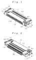
- FIGS. 1 through 11 show a first embodiment of the present invention.
- a connector shown in the said FIGS. comprises a connector main body 10 into which a flexible circuit 1 to be inserted as an object to be connected, a plurality of contacts 20 arranged with spaces in the width direction of the connector main body 10, a press member 30 capable of rotating for pushing each contacts toward the flexible circuit 1 side which is inserted into the connector main body 10, a pair of left/right fixing members 40 for fixing the connector main body 10 to a circuit board which is not shown in any of FIGS., and a pair of left/right lock members 50 with which the flexible circuit 1 is engaged.
- the flexible circuit 1 is configured of what is called a flexible flat cable (FFC) or a flexible printed circuit (FPC), a plurality of electrical metal terminals (not shown) is provided at an upper face of a tip side of the flexible circuit 1 with spaces in the width direction. Also, dented portions 1a as the engagement portion for being engaged with the lock members 50 is provided at both end sides in the width direction of the flexible circuit 1, when the flexible circuit 1 is inserted into a predetermined position of the connector main body 10 (position for connecting with the contacts 20), each of the lock members 50 is engaged with the dented portions respectively.
- FFC flexible flat cable
- FPC flexible printed circuit
- the connector main body 10 is made of a synthetic resin molding, and an insertion slot 10a for inserting the flexible circuit 1 is provided at a front face of the connector main body 10.
- the connector main body 10 comprises an upper face portion 11, a bottom face portion 12, and left and right side face portions 13, the upper face portion 11 is configured only at the front end side of the upper face of the connector main body 10. Also, both of the left and right sides of the upper face portion 11 are opened to expose the inside of the connector main body 10, and the lock members 50 are disposed at the exposed portions.
- Each of the contacts 20 is made of a conductive metal plate which is arranged at the bottom face portion 12 of the connector main body 10 with spaces in the width direction.
- Each of the contacts 20 comprises a fixing piece portion 21 for fixing with the bottom face portion 12, a first movable piece portion 22 pushed by the press member 30, a second movable piece portion 23 arranged at the lower side of the fist movable piece portion 22, and a springy piece portion 24 formed between the second movable portion 23 and the fixing piece portion 21.
- the fixing piece portion 21 extends in the front-rear direction of the connector main body 10, a front end portion 21a thereof is pushed into a slit at the bottom face portion 12 side.
- a first convex portion 21c capable of rotatably engaging with the press member 30 is provided at the rear end side of the fixing piece portion 21, and a first concave portion 21d is provided at the front side of the first convex portion 21c.
- the first movable piece portion 22 extends in the vertical direction of the connector main body 10, a first contacting portion 22a for contacting the upper face of the flexible circuit 1 is provided so as to protrude downwardly at the front end of the movable piece portion 22.
- a first abutting portion 22b and a second abutting portion 22c for abutting against the press member 30 are provided at the rear end of the first movable piece portion 22, the first contacting portion 22b is provided at the rear end side of the first movable piece portion 22 downwardly inclining from upper side to the lower side, the second abutting portion 22c is formed approximately horizontally in the front-rear direction at the bottom end face of the first movable piece portion 22.
- the second movable piece portion 23 extends toward the front-rear direction of the connector main body 10, a second contacting portion 23a for contacting the upper side of the flexible circuit 1 is provided to protrude downwardly at the front end of the second movable piece portion 23.
- the second movable piece portion 23 is shorter than the first movable piece portion 22 in the front-rear direction of the connector main body 10, and the width of the second movable piece portion 23 is smaller in the front-rear direction than the width of the first movable piece portion 22.
- the second contacting portion 23a is placed at the rear side of the first contacting portion 22a, the lower end of the second contacting portion 23a is as the same height as the lower end of the first contacting portion 22a (contacting point).
- the rear end side of the second movable piece portion 23 bends upwardly, and, extends toward the rear end side of the first movable piece portion 22 (ahead of the second abutting portion 22c), the first movable piece portion 22 is supported by the rear end side of the second movable piece portion 23.
- the springy piece portion 24 extends in the vertical direction from an approximate center in the front-rear direction of the fixing piece portion 21 to an approximate center in the front-rear direction of the second movable piece portion 23, the first movable piece portion 22 and the second movable piece portion 23 are respectively supported so that the front end sides and rear end sides of the first movable piece portion 22 and the second movable piece portion 23 are respectively movably in the vertical direction.
- the press member 30 is made of a synthetic resin molding, the press member 30 covers the upper face in the rear end side of the connector main body 10.
- a rotation support portion 31 protruding toward the inside of the connector main body 10 is provided at the rear end side of the press member 30, a second convex portion 31a for engaging with the first concave portion 21c of the contacts 20 is provided at the tip of the rotation support portion 31, and a second convex portion 31b for engaging with the first concave portion 21d of the contacts 20 is provided at the front part of the second concave portion 31a.
- the press member 30 rotates on a fulcrum where the second concave portion 31a is contacted with the first convex portion 21c by engaging the second concave portion 31a with the first convex portion 21c, and the press member 30 rotates on a fulcrum where the second convex portion 31b is contacted with the first concave portion 21d by engaging the second convex portion 31b with the first concave portion 21d.
- the said fulcrum is located between the front end side and the rear end side of the press member 30, when the front end side of the press member 30 is pushed downwardly, the rear end side thereof moves upwardly and locks the press member 30, and when the rear end side of the press member 30 is pushed downwardly, the front end side thereof moves upwardly and releases the press member 30.
- a press portion 31c for abutting against the first abutting portion 22b and the second abutting portion 22c of the contacts 20 is provided at the rotation support portion 31, the press portion 31c protrude in a chevron shape.
- Protruding portions 32 for regulating the lock members 50 from moving in the width direction is provided at the both end sides in the width direction of the press member 30, and each of the protruding portions 32 protrude downwardly.
- the fixing members 40 are made of a metal plate arranged at the both end sides in the width direction of the connector main body 10, each of the fixing members 40 are fixed to the both side face portions 13 of the connector main body 10.
- Connecting portions 41 which connects to a circuit board, which is not shown in any of FIGS., are provided at the bottom end side of the fixing member 40, each of the connecting portions 41 extends outside in the width direction of the connector main body 10.
- Each of the lock members 50 are made of a metal plate integratedly formed with the fixing members 40, each of the lock members 50 is arranged at the both ends side in the width direction of the connector main body 10.
- the lock members 50 comprise an engagement portion 51 for being engaged with the dented portion 1a of the flexible circuit 1, a movable portion 52 extending backwardly from the engagement portion 51, and a springy portion 53 extending to the fixing members 40 from the rear end of the movable portion 53.
- the engagement portion 51 and the movable portion 52 move toward the width direction of the connector main body 10 by the springy portion 53 deforming springy.
- the engagement portion 51 is formed in a chevron shape so as to protrude toward inside in the width direction of the connector main body 10, the movable portion 52 extends straight in the front-rear direction of the connector main body 10.
- the springy portion 53 extends toward the inside in the width direction of the connector main body 10 from the rear end of the movable portion 52, and the springy portion 53 is bent to extend toward the outside in the width direction of the connector main body 10 to the fixing members 40, the engagement portion 51 and the movable portion 52 move in the width direction of the connector main body 10 by deforming the springy portion 53 springy toward the front-rear direction of the connector main body 10.
- a slit into which the protruding portion 32 of the press member 30 can be inserted is provided between the movable portion 52 and the side face portion 13 of the connector main body 10, and when the movable portion 52 is moved toward the outside in the width direction of the connector main body 10, the protruding portion 32 abuts against the movable portion 52 so that the protruding portion 32 is regulated from being inserted in the said slit.
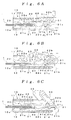
- the flexible circuit 1 is inserted into a predetermined position in the connector main body 10 from the insertion slot 10a, as shown in FIG.5B , when the front end side of the press member 30 is pushed downwardly, while the second concave portion 31a of the press member 30 is engaged with the first convex portion 21c, the press member 30 rotates on a place where the second concave portion 31a contacts with the first convex portion 21c as a first rotation fulcrum P1, the press portion 31c of the press member 30 abuts with the first abutting portion 22b of the first movable piece portion 22 toward the front direction.
- the first abutting portion 22b inclines downwardly toward the front direction, thus, the rear end side of the first movable piece portion 22 is pushed upwardly and the front end side thereof is inclined due to the press portion 31c, and, in accordance with this, the rear end side of the second movable piece portion 23 is pushed upwardly and the front end side thereof is inclined.
- the first contacting portion 22a and the second contacting portion 23a touch tightly the upper face of the flexible circuit 1, and each of the movable piece portions 22 and 23 is electrically connected to the flexible circuit 1.
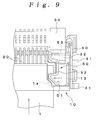
- the tip of the flexible circuit 1 abuts against the inclined face of the engagement portion 51 of the lock members 50, as shown in FIG.8 , the engagement portion 51 and movable portion 52 are moved toward outside in the width direction of the connector main body 10. Further, when the flexible circuit 1 is inserted into a predetermined position, as shown in FIG.9 , the engagement portion 51 is engaged with the dented portion 1a of the flexible circuit 1, and the engagement portion 51 and the movable portion 52 are moved toward inside in the width direction. By this, the connector main body 10 temporarily holds the flexible circuit 1 by the lock members 50.
- the tip of the flexible circuit 1 inserted into the connector main body 10 abuts against the lock members 50, when the pushing member 30 is rotated toward one side while the lock member 50 is moved toward the outside in the width direction of the connector main body 10, the protrude portion 32 of the pushing member 30 abuts against the lock members 50, which regulates the rotation of the pushing member 30, when the pushing member 30 is rotated toward one direction while the lock members 50 are returned toward inside in the width direction of the connector main body 10, the pushing member 30 are allowed to rotate.
- the pushing member 30 does not rotate to the closed position when the flexible circuit 1 is inserted imperfectly. Therefore, it becomes possible to effectively prevent an incomplete connection caused by the imperfect insertion of the flexible circuit 1.
- the flexible circuit 1 is temporarily held by engaging the flexible circuit 1 with the lock members 50, the flexible circuit 1 is not displaced when the pushing member 30 is rotated, a connection operation of the flexible circuit 1 can easily and certainly be conducted.
- the pushing member 30 is rotated toward the closing position while the flexible circuit 1 is temporarily held by the lock members 50, the movement of the lock members 50 toward outside in the width direction is regulated by the protrude portion 32 of the pushing member 30. So, the flexible circuit 1 can completely be locked by each of the lock members 50. Therefore, it becomes possible to connect the flexible circuit 1 certainly.
- the lock members 50 can be moved in the width direction of the connector main body 10, it is unnecessary to enlarge the connector main body 10 in the height direction, which is extremely advantageous to make connector main body 10 thinner.
- the press member 30 abuts against the lock members 50 which moves toward outside in the width direction of the flexible circuit 1 so that the press force is not applied to the flexible circuit 1 from the lock members 50. Therefore, it is advantageous that the flexible circuit 1 does not get damaged.
- the connector main body 10 is formed so that a state of the lock member 50 moving toward the outside in the width direction of the connector main body 10 can be seen from the outside.
- the imperfect insertion of the flexible circuit 1 can also be confirmed by watching inspection. Therefore, it certainly prevents a connection when the flexible circuit 1 is inserted imperfectly.
- the lock members 50 are formed integratedly with the fixing member 40 for fixing the connector main body 10 at outside. So, a number of parts and an assembly man-hour can be reduced. Therefore, it becomes possible to improve the productivity.
- the lock members 50 and the fixing members 40 are made of a conductive material, for example, at a production line, in a case in which an electrode is inserted into the side of the lock members 50 of the connector to which the flexible circuit 1 is connected, and then the electrode touches the lock members 50 which is being moved in the width direction due to the imperfect insertion of the flexible circuit 1, the electrode becomes electrically connected to an other electrode to which the fixing member 40 is connected.
- it can be used for a checking process for detecting the imperfect insertion.
- the above embodiment shows the lock member 50 integratedly formed with the fixing member 40, however, they can be formed separately, or the connector can be made without the fixing members 40.
- 1... flexible circuit 1a... dented portion, 20... contacts, 21... fixing piece portion, 21c... first convex portion, 21d... first concave portion, 22... first movable piece portion, 22a... first contacting portion, 22b... first abutting portion, 22c... the second abutting portion, 23... first movable piece portion, 23a... second abutting portion, 24... springy piece portion, 40... fixing member, 50... lock member.
Landscapes
- Coupling Device And Connection With Printed Circuit (AREA)
- Details Of Connecting Devices For Male And Female Coupling (AREA)
Applications Claiming Priority (2)
| Application Number | Priority Date | Filing Date | Title |
|---|---|---|---|
| JP2009133980A JP4410306B1 (ja) | 2009-06-03 | 2009-06-03 | コネクタ |
| PCT/JP2010/057249 WO2010140437A1 (fr) | 2009-06-03 | 2010-04-23 | Connecteur |
Publications (2)
| Publication Number | Publication Date |
|---|---|
| EP2429043A1 true EP2429043A1 (fr) | 2012-03-14 |
| EP2429043A4 EP2429043A4 (fr) | 2013-06-19 |
Family
ID=41739254
Family Applications (1)
| Application Number | Title | Priority Date | Filing Date |
|---|---|---|---|
| EP10773827.0A Withdrawn EP2429043A4 (fr) | 2009-06-03 | 2010-04-23 | Connecteur |
Country Status (7)
| Country | Link |
|---|---|
| US (1) | US8172592B2 (fr) |
| EP (1) | EP2429043A4 (fr) |
| JP (1) | JP4410306B1 (fr) |
| KR (1) | KR101161852B1 (fr) |
| CN (1) | CN102057539B (fr) |
| TW (1) | TW201101613A (fr) |
| WO (1) | WO2010140437A1 (fr) |
Cited By (1)
| Publication number | Priority date | Publication date | Assignee | Title |
|---|---|---|---|---|
| EP2442411A4 (fr) * | 2009-06-10 | 2013-03-27 | Iriso Electronics Co Ltd | Connecteur |
Families Citing this family (18)
| Publication number | Priority date | Publication date | Assignee | Title |
|---|---|---|---|---|
| JP4919361B2 (ja) * | 2009-09-07 | 2012-04-18 | 株式会社アイペックス | コネクタ装置 |
| JP4568791B1 (ja) * | 2009-12-16 | 2010-10-27 | イリソ電子工業株式会社 | コネクタ |
| JP5556261B2 (ja) * | 2010-03-12 | 2014-07-23 | オムロン株式会社 | コネクタ |
| JP2012004072A (ja) * | 2010-06-21 | 2012-01-05 | Omron Corp | コネクタ |
| EP2562880A1 (fr) * | 2011-08-22 | 2013-02-27 | Dai-Ichi Seiko Co., Ltd. | Connecteur électrique |
| JP5779078B2 (ja) | 2011-11-28 | 2015-09-16 | 日本航空電子工業株式会社 | コネクタ |
| JP5549821B2 (ja) * | 2012-04-17 | 2014-07-16 | 第一精工株式会社 | 電気コネクタ |
| JP5809203B2 (ja) * | 2013-07-04 | 2015-11-10 | ヒロセ電機株式会社 | 平型導体用電気コネクタ |
| KR101512113B1 (ko) | 2013-08-07 | 2015-04-14 | 엘에스엠트론 주식회사 | 록킹 부재가 개선된 플랫 케이블 접속용 커넥터 |
| JP6452393B2 (ja) * | 2014-11-13 | 2019-01-16 | 日本航空電子工業株式会社 | コネクタ |
| CN109478746B (zh) * | 2016-07-13 | 2020-06-30 | 京瓷株式会社 | 连接器 |
| JP6785598B2 (ja) * | 2016-08-26 | 2020-11-18 | ヒロセ電機株式会社 | 平型導体用電気コネクタ |
| JP6458786B2 (ja) * | 2016-09-15 | 2019-01-30 | Smk株式会社 | コネクタ |
| JP6540674B2 (ja) * | 2016-12-09 | 2019-07-10 | 第一精工株式会社 | 電気コネクタ |
| JP6658798B2 (ja) * | 2018-06-05 | 2020-03-04 | 第一精工株式会社 | 電気コネクタ及びコネクタ装置 |
| JP2023180155A (ja) * | 2022-06-08 | 2023-12-20 | イリソ電子工業株式会社 | 平型導体用コネクタ |
| CN115021016B (zh) * | 2022-06-17 | 2022-12-20 | 皓星智能装备(东莞)有限公司 | 马达定子三相端子取电结构及取电方法 |
| US12555933B2 (en) * | 2022-07-28 | 2026-02-17 | Te Connectivity Solutions Gmbh | Electrical connector |
Family Cites Families (13)
| Publication number | Priority date | Publication date | Assignee | Title |
|---|---|---|---|---|
| JP2000030784A (ja) * | 1998-05-08 | 2000-01-28 | Japan Aviation Electronics Ind Ltd | 電気コネクタ |
| US6332801B1 (en) * | 1999-09-01 | 2001-12-25 | Hirose Electric Co., Ltd. | Insulation replacement electrical connector |
| JP2002352890A (ja) * | 2001-05-25 | 2002-12-06 | Sumitomo Wiring Syst Ltd | コネクタ |
| JP3605586B2 (ja) * | 2001-09-25 | 2004-12-22 | 日本圧着端子製造株式会社 | フレキシブル基板用コネクタ |
| JP4931417B2 (ja) * | 2005-12-27 | 2012-05-16 | モレックス インコーポレイテド | ケーブル接続用コネクタ |
| US7179118B1 (en) * | 2006-03-15 | 2007-02-20 | Hon Hai Precision Ind. Co., Ltd. | Connector for flexible printed circuit |
| JP4869027B2 (ja) * | 2006-11-01 | 2012-02-01 | モレックス インコーポレイテド | ケーブル用コネクタ |
| JP5084244B2 (ja) * | 2006-12-18 | 2012-11-28 | イリソ電子工業株式会社 | コネクタ |
| JP4953904B2 (ja) * | 2007-04-27 | 2012-06-13 | モレックス インコーポレイテド | ケーブル用コネクタ |
| CN101369697B (zh) * | 2007-08-17 | 2010-06-16 | 富士康(昆山)电脑接插件有限公司 | 电连接器 |
| JP2009070757A (ja) * | 2007-09-18 | 2009-04-02 | Iriso Denshi Kogyo Kk | コネクタ |
| CN201191666Y (zh) * | 2008-01-29 | 2009-02-04 | 富士康(昆山)电脑接插件有限公司 | 电连接器 |
| JP4605817B2 (ja) * | 2008-04-11 | 2011-01-05 | 日本航空電子工業株式会社 | コネクタ |
-
2009
- 2009-06-03 JP JP2009133980A patent/JP4410306B1/ja not_active Expired - Fee Related
-
2010
- 2010-04-23 CN CN201080001757.2A patent/CN102057539B/zh not_active Expired - Fee Related
- 2010-04-23 US US12/996,653 patent/US8172592B2/en not_active Expired - Fee Related
- 2010-04-23 EP EP10773827.0A patent/EP2429043A4/fr not_active Withdrawn
- 2010-04-23 KR KR1020107025610A patent/KR101161852B1/ko not_active Expired - Fee Related
- 2010-04-23 WO PCT/JP2010/057249 patent/WO2010140437A1/fr not_active Ceased
- 2010-05-27 TW TW099116962A patent/TW201101613A/zh unknown
Cited By (1)
| Publication number | Priority date | Publication date | Assignee | Title |
|---|---|---|---|---|
| EP2442411A4 (fr) * | 2009-06-10 | 2013-03-27 | Iriso Electronics Co Ltd | Connecteur |
Also Published As
| Publication number | Publication date |
|---|---|
| JP4410306B1 (ja) | 2010-02-03 |
| JP2012064310A (ja) | 2012-03-29 |
| CN102057539A (zh) | 2011-05-11 |
| TW201101613A (en) | 2011-01-01 |
| US8172592B2 (en) | 2012-05-08 |
| WO2010140437A1 (fr) | 2010-12-09 |
| CN102057539B (zh) | 2013-05-22 |
| KR20110016887A (ko) | 2011-02-18 |
| KR101161852B1 (ko) | 2012-07-03 |
| US20110092091A1 (en) | 2011-04-21 |
| EP2429043A4 (fr) | 2013-06-19 |
Similar Documents
| Publication | Publication Date | Title |
|---|---|---|
| EP2429043A1 (fr) | Connecteur | |
| EP2442411A1 (fr) | Connecteur | |
| EP2439819B1 (fr) | Connecteur | |
| US20120289093A1 (en) | Connector | |
| CN103441378B (zh) | 连接器 | |
| TW201834331A (zh) | 連接器裝置 | |
| US9590335B1 (en) | Connector | |
| CN103140992B (zh) | 连接器 | |
| CN109478746A (zh) | 连接器 | |
| CN102570165A (zh) | 连接器 | |
| HK1124695A (en) | Connector |
Legal Events
| Date | Code | Title | Description |
|---|---|---|---|
| PUAI | Public reference made under article 153(3) epc to a published international application that has entered the european phase |
Free format text: ORIGINAL CODE: 0009012 |
|
| 17P | Request for examination filed |
Effective date: 20101116 |
|
| AK | Designated contracting states |
Kind code of ref document: A1 Designated state(s): AT BE BG CH CY CZ DE DK EE ES FI FR GB GR HR HU IE IS IT LI LT LU LV MC MK MT NL NO PL PT RO SE SI SK SM TR |
|
| DAX | Request for extension of the european patent (deleted) | ||
| A4 | Supplementary search report drawn up and despatched |
Effective date: 20130521 |
|
| RIC1 | Information provided on ipc code assigned before grant |
Ipc: H01R 12/70 20110101ALI20130514BHEP Ipc: H01R 12/79 20110101ALI20130514BHEP Ipc: H01R 13/639 20060101ALI20130514BHEP Ipc: H01R 12/88 20110101ALI20130514BHEP Ipc: H01R 12/59 20110101ALI20130514BHEP Ipc: H01R 13/64 20060101AFI20130514BHEP |
|
| STAA | Information on the status of an ep patent application or granted ep patent |
Free format text: STATUS: THE APPLICATION IS DEEMED TO BE WITHDRAWN |
|
| 18D | Application deemed to be withdrawn |
Effective date: 20131218 |