EP2429044A1 - Elektrisches Installationsgerät - Google Patents
Elektrisches Installationsgerät Download PDFInfo
- Publication number
- EP2429044A1 EP2429044A1 EP10157341A EP10157341A EP2429044A1 EP 2429044 A1 EP2429044 A1 EP 2429044A1 EP 10157341 A EP10157341 A EP 10157341A EP 10157341 A EP10157341 A EP 10157341A EP 2429044 A1 EP2429044 A1 EP 2429044A1
- Authority
- EP
- European Patent Office
- Prior art keywords
- electrical installation
- installation device
- electrical
- lighting
- design
- Prior art date
- Legal status (The legal status is an assumption and is not a legal conclusion. Google has not performed a legal analysis and makes no representation as to the accuracy of the status listed.)
- Granted
Links
Images


Classifications
-
- H—ELECTRICITY
- H01—ELECTRIC ELEMENTS
- H01R—ELECTRICALLY-CONDUCTIVE CONNECTIONS; STRUCTURAL ASSOCIATIONS OF A PLURALITY OF MUTUALLY-INSULATED ELECTRICAL CONNECTING ELEMENTS; COUPLING DEVICES; CURRENT COLLECTORS
- H01R13/00—Details of coupling devices of the kinds covered by groups H01R12/70 or H01R24/00 - H01R33/00
- H01R13/66—Structural association with built-in electrical component
- H01R13/665—Structural association with built-in electrical component with built-in electronic circuit
- H01R13/6658—Structural association with built-in electrical component with built-in electronic circuit on printed circuit board
-
- H—ELECTRICITY
- H01—ELECTRIC ELEMENTS
- H01H—ELECTRIC SWITCHES; RELAYS; SELECTORS; EMERGENCY PROTECTIVE DEVICES
- H01H9/00—Details of switching devices, not covered by groups H01H1/00 - H01H7/00
- H01H9/18—Distinguishing marks on switches, e.g. for indicating switch location in the dark; Adaptation of switches to receive distinguishing marks
-
- H—ELECTRICITY
- H01—ELECTRIC ELEMENTS
- H01R—ELECTRICALLY-CONDUCTIVE CONNECTIONS; STRUCTURAL ASSOCIATIONS OF A PLURALITY OF MUTUALLY-INSULATED ELECTRICAL CONNECTING ELEMENTS; COUPLING DEVICES; CURRENT COLLECTORS
- H01R13/00—Details of coupling devices of the kinds covered by groups H01R12/70 or H01R24/00 - H01R33/00
- H01R13/66—Structural association with built-in electrical component
- H01R13/717—Structural association with built-in electrical component with built-in light source
-
- H—ELECTRICITY
- H01—ELECTRIC ELEMENTS
- H01R—ELECTRICALLY-CONDUCTIVE CONNECTIONS; STRUCTURAL ASSOCIATIONS OF A PLURALITY OF MUTUALLY-INSULATED ELECTRICAL CONNECTING ELEMENTS; COUPLING DEVICES; CURRENT COLLECTORS
- H01R24/00—Two-part coupling devices, or either of their cooperating parts, characterised by their overall structure
- H01R24/76—Two-part coupling devices, or either of their cooperating parts, characterised by their overall structure with sockets, clips or analogous contacts and secured to apparatus or structure, e.g. to a wall
- H01R24/78—Two-part coupling devices, or either of their cooperating parts, characterised by their overall structure with sockets, clips or analogous contacts and secured to apparatus or structure, e.g. to a wall with additional earth or shield contacts
Definitions
- the present invention is based on a designed according to the preamble of the main claim electrical installation device of building system technology.
- Such electrical installation equipment is usually intended to meet certain functions in buildings depending on the device type. Often, such electrical installation equipment with respect to the device type as orientation light, switching device, grounded electrical outlet, etc. are formed. In part, such electrical installation devices are equipped with a lighting device whose lamps are designed as LEDs.
- a the preamble of the main claim corresponding electrical installation device is through the DE 103 34 247 B3 known.
- This electrical installation device is designed as a protective contact socket, which has for the realization of a functional lighting a lighting device which is provided with a LED designed as a light source.
- About two connecting lines and a circuit board is designed as an LED bulb electrically conductive with arranged in the base part contact parts of the electrical safety socket.
- the present invention is therefore based on the task lighting equipment of electrical installation equipment to design so that can be used universally for different types of installation equipment similarly trained lighting devices.
- the lighting device is constructed in a modular manner and is provided protected in a separate housing, whereby the handling is considerably simplified both during manufacture, and during installation on site or in the building.
- such installation devices generally offer the possibility of receiving such a trained illumination device in a modular manner, it is particularly advantageous that such electrical installation devices can be equipped with such a lighting device as needed, so that a subsequent equipment already installed devices on site in a simple manner is possible ,
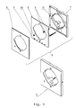
- such an electrical installation device of building system technology consists mainly of a base part 1, a fixable on the base part 1 support ring 2, a fixed to the support ring 2 and the base part 1 lighting device 3, and a design part 4 and in FIG. 2 and FIG. 3 darg Popeen closer, arranged in the base part 1, necessary for the function contact parts.
- the lighting device 3 is constructed in a modular manner and consists of a with a plurality of light sources 5 and a light sensor 50 fitted circuit board 6, which is received by a lower housing part 7 and covered by a housing upper part 8.
- the lighting device 3 thus represents an independently handleable, protected by its own housing module.
- Two trained as contact springs 9 contact elements provide the electrically conductive connection between the circuit board 6 and the light sources 5 and the light sensor 50 and the necessary contact function parts of the base part. 1 ago.
- the two contact springs 9 come into contact with their one end area contact-making conductor tracks of the printed circuit board 6 and with its other end portion contact-making in each case to an associated contact part of the base part 1 to the plant, in FIG. 2 and FIG.
- the two contact springs 9 are each formed as helical compression springs, so that the necessary for a secure contact contact pressure is readily established.
- Isolierstoffdome 10 are integrally formed on the outer wall of the lower housing part.
- the lighting means 5 of the lighting device 3 are each formed as an LED.
- the contact parts necessary for the function of the base part 1 are on the one hand as spring terminals trained and provided depending on the design of the electrical installation device to z. B. the connection of the electrical lines and / or on the other hand, the contact receiving of connector pins z. B. to be introduced electrical safety plug (see in particular FIG. 2 ) to give contact. On the other hand, these contact parts can be designed as switch contact parts just as well.
- the lower housing part 7 of the lighting device 3 is provided at one of its design part 4 associated narrow sides with an elongated slot for the passage of the light emitted by the bulbs 5 light.
- the lighting device 3 is associated with this slot on the existing design part 4 light guide so that the light emitted by the bulbs 5 light is desired radiated into the environment.
- the design part 4 has a cylindrically shaped light sensor cover 60, which is received in a form-fitting manner by a circular opening formed in the design part 4 and assigned to the light sensor 50 arranged on the circuit board 6 of the lighting device 3.
- the light sensor 50 serves to enable the lighting device 3 to be switched on or off automatically depending on the intensity of the ambient light.
- the fixed to the base part 1 support ring 2 is made of metal and provides for the lighting device 3 is a stable edition possibility.
- the design part 4 integrally has a cover frame 4a and a cover center piece 4b. In order for the accommodation of the lighting device 3 enough space between the top of the support ring 2 and the bottom of the design part 4 is created, this has corresponding dimensions.
- the base part 1 is part of an orientation light and has according to its functions, the necessary functional components.
- the design part 4 integrally has a cover frame 4a and a socket center piece 4c. So for the Housing the lighting device 3 enough space between the top of the support ring 2 and the bottom of the design part 4 is created, this has corresponding dimensions.
- the base part 1 is part of a socket outlet and has according to its functions, the necessary functional components.
- this has a frame-shaped design with a provided at a central point breakthrough.
- the breakthrough is therefore at least slightly larger than is necessary for the passage of a conventional pot of a socket center piece 4c.
Landscapes
- Engineering & Computer Science (AREA)
- Microelectronics & Electronic Packaging (AREA)
- Non-Portable Lighting Devices Or Systems Thereof (AREA)
- Arrangement Of Elements, Cooling, Sealing, Or The Like Of Lighting Devices (AREA)
Abstract
Description
- Die vorliegende Erfindung geht von einem gemäß Oberbegriff des Hauptanspruches konzipierten elektrischen Installationsgerät der Gebäudesystemtechnik aus.
- Derartige elektrische Installationsgeräte sind in der Regel dafür vorgesehen, je nach Gerätetyp bestimmte Funktionen in Gebäuden zu erfüllen. Oftmals sind solche elektrischen Installationsgeräte hinsichtlich des Gerätetyps als Orientierungsleuchte, Schaltgerät, Schutzkontaktsteckdose usw. ausgebildet. Teilweise sind solche elektrischen Installationsgeräte mit einer Beleuchtungseinrichtung ausgerüstet, deren Leuchtmittel als LED ausgebildet sind.
- Ein dem Oberbegriff des Hauptanspruches entsprechendes elektrisches Installationsgerät ist durch die
DE 103 34 247 B3 bekannt geworden. Dieses elektrische Installationsgerät ist als Schutzkontaktsteckdose ausgebildet, wobei dieses zur Realisierung einer Funktionsbeleuchtung eine Beleuchtungseinrichtung aufweist, welche mit einem als LED ausgebildeten Leuchtmittel versehen ist. Über zwei Verbindungsleitungen und eine Leiterplatte steht das als LED ausgebildete Leuchtmittel elektrisch leitend mit im Sockelteil angeordneten Kontaktteilen der elektrischen Schutzkontaktsteckdose in Verbindung. - Des weiteren ist es durch die
DE 102 33 331 C1 bekannt, bei einem elektrischen Schalter der Gebäudesystemtechnik dessen Seitenbereiche zum Zwecke der Ausleuchtung mit flächig ausgeführten Lichtleitelementen zu versehen. Auf einer im Innenraum des elektrischen Schalters angeordneten Leiterplatte sind Leuchtdioden der Beleuchtungsseinrichtung vorhanden, welche ihr abgestrahltes Licht in die flächig ausgeführten Lichtleitelemente einkoppeln, so dass eine akzentvolle Ausleuchtung realisiert ist. - Derartige Installationsgeräte sind jedoch so ausgestaltet, dass nur speziell auf die vorliegenden konstruktiven Gegebenheiten abgestimmte Beleuchtungseinrichtungen verwendet werden können.
- Der vorliegenden Erfindung liegt deshalb die Aufgabe zugrunde Beleuchtungseinrichtungen von elektrischen Installationsgeräten derart auszugestalten, so dass für verschiedene Gerätetypen von Installationsgeräten gleichartig ausgebildete Beleuchtungseinrichtungen universell Verwendung finden können.
- Diese Aufgabe wird durch die im Hauptanspruch angegebenen Merkmale gelöst.
- Bei einem solchermaßen ausgebildeten elektrischen Installationsgerät ist besonders vorteilhaft, dass die Beleuchtungseinrichtung modulartig aufgebaut ist und in einem eigenen Gehäuse geschützt zur Verfügung gestellt wird, wodurch das Handling sowohl bei der Herstellung, als auch bei der Montage vor Ort bzw. im Gebäude erheblich vereinfacht ist.
- Weil solche Installationsgeräte generell die Möglichkeit bieten, eine derart ausgebildete Beleuchtungseinrichtung modulartig aufzunehmen, ist besonders vorteilhaft, dass solche elektrischen Installationsgeräte bedarfsweise mit einer derartigen Beleuchtungseinrichtung ausgerüstet werden können, so dass auch eine nachträgliche Ausrüstung bereits installierter Geräte vor Ort auf einfache Art und Weise möglich ist.
- Weitere vorteilhafte Ausgestaltungen des erfindungsgemäßen Gegenstandes sind in den Unteransprüchen angegeben. Anhand zweier in den Zeichnungen näher dargestellten Ausführungsbeispiele sei der erfindungsgemäße Gegenstand näher erläutert. Dabei zeigen:
- Fig. 1:
- prinziphaft eine solche Beleuchtungseinrichtung für elektrische Installationsgeräte räumlich in Explosionsdarstellung und als Modul im Zusammenbau;
- Fig. 2:
- prinziphaft ein als Schutzkontaktsteckdose ausgebildetes elektrisches Installationsgerät mit einer Beleuchtungseinrichtung gemäß
Figur 1 , räumlich in Explosionsdarstellung; - Fig. 3:
- prinziphaft ein als Orientierungsleuchte ausgebildetes elektrisches Installationsgerät mit einer Beleuchtungseinrichtung gemäß
Figur 1 , räumlich in Explosionsdarstellung. - Wie aus den Zeichnungen hervorgeht, besteht ein solches elektrisches Installationsgerät der Gebäudesystemtechnik hauptsächlich aus einem Sockelteil 1, einem am Sockelteil 1 festlegbaren Tragring 2, einer am Tragring 2 festgelegten und am Sockelteil 1 angeschlossenen Beleuchtungseinrichtung 3, sowie einem Designteil 4 und den in
Figur 2 undFigur 3 näher dargstellten, im Sockelteil 1 angeordneten, zur Funktion notwendigen Kontaktteilen. - Wie des weiteren insbesondere aus
Figur 1 hervorgeht, ist die Beleuchtungseinrichtung 3 modulartig aufgebaut und besteht aus einer mit mehreren Leuchtmitteln 5 und einem Lichtsensor 50 bestückten Leiterplatte 6, welche von einem Gehäuseunterteil 7 aufgenommen und von einem Gehäuseoberteil 8 abgedeckt ist. Die Beleuchtungseinrichtung 3 stellt also ein eigenständig händelbares, von einem eigenen Gehäuse geschütztes Modul dar. Zwei als Kontaktfedern 9 ausgebildete Kontaktelemente stellen die elektrisch leitende Verbindung zwischen der Leiterplatte 6 bzw. den Leuchtmitteln 5 sowie dem Lichtsensor 50 und den zur Funktion notwendigen Kontaktteilen des Sockelteils 1 her. Die beiden Kontaktfedern 9 kommen dazu mit ihrem einen Endbereich kontaktgebend an Leiterbahnen der Leiterplatte 6 und mit ihrem anderen Endbereich kontaktgebend jeweils an einem zugeordneten Kontaktteil des Sockelteils 1 zur Anlage, die inFigur 2 undFigur 3 näher dargestellt sind. Die beiden Kontaktfedern 9 sind jeweils als Schraubendruckfedern ausgebildet, so dass der für eine sichere Kontaktgabe notwendige Kontaktdruck ohne weiteres aufgebaut wird. Zur Aufnahme, Führung und Isolierung der beiden Kontaktfedern 9 sind an die Außenwand des Gehäuseunterteils 7 zwei Isolierstoffdome 10 angeformt. Die Leuchtmittel 5 der Beleuchtungseinrichtung 3 sind jeweils als LED ausgebildet. Die zur Funktion notwendigen Kontaktteile des Sockelteils 1 sind einerseits als Federklemmen ausgebildet und je nach Ausführung des elektrischen Installationsgerätes dazu vorgesehen z. B. den Anschluss der elektrischen Leitungen und/oder andererseits die kontaktgebende Aufnahme von Steckerstiften z. B. eines einzuführenden elektrischen Schutzkontaktsteckers (siehe insbesondereFigur 2 ) kontaktgebend zu ermöglichen. Genau so gut können diese Kontaktteile andererseits auch als Schaltkontaktteile ausgebildet sein. - Wie des weiteren aus den Figuren hervorgeht, ist das Gehäuseunterteil 7 der Beleuchtungseinrichtung 3 an einer seiner dem Designteil 4 zugeordneten Schmalseiten mit einem länglich ausgeführten Schlitz für den Durchtritt des von den Leuchtmitteln 5 abgegebenen Lichts versehen. Die Beleuchtungseinrichtung 3 ist dabei mit diesem Schlitz dem am Designteil 4 vorhandenen Lichtleitelement so zugeordnet, dass das von den Leuchtmitteln 5 abgegebene Licht wunschgemäß in die Umgebung abgestrahlt wird. Des weiteren weist das Designteil 4 eine zylinderförmig ausgebildete Lichtsensorabdeckung 60 auf, welche formschlüssig von einer im Designteil 4 vorhandenen, kreisförmig ausgebildeten Öffnung aufgenommen und dem auf der Leiterplatte 6 der Beleuchtungseinrichtung 3 angeordneten Lichtsensor 50 zugeordnet ist. Der Lichtsensor 50 dient dazu, dass die Beleuchtungseinrichtung 3 abhängig von der Stärke des Umgebungslichts automatisch ein- bzw. ausgeschaltet werden kann.
- Der am Sockelteil 1 festgelegte Tragring 2 besteht aus Metall und stellt für die Beleuchtungseinrichtung 3 eine stabile Auflagenmöglichkeit dar.
- Wie insbesondere aus
Figur 3 hervorgeht, weist das Designteil 4 einstückig einen Abdeckrahmen 4a und ein Abdeckzentralstück 4b auf. Damit für die Unterbringung der Beleuchtungseinrichtung 3 genügend Raum zwischen der Oberseite des Tragrings 2 und der Unterseite des Designteils 4 geschaffen ist, weist dieses entsprechende Abmessungen auf. Wie des weiteren insbesondere ausFigur 3 hervorgeht, ist das Sockelteil 1 Bestandteil einer Orientierungsleuchte und weist entsprechend seiner Funktionen die notwendigen Funktionskomponenten auf. - Wie insbesondere aus
Figur 2 hervorgeht, weist das Designteil 4 einstückig einen Abdeckrahmen 4a und ein Steckdosenzentralstück 4c auf. Damit für die Unterbringung der Beleuchtungseinrichtung 3 genügend Raum zwischen der Oberseite des Tragrings 2 und der Unterseite des Designteils 4 geschaffen ist, weist dieses entsprechende Abmessungen auf. Wie des weiteren insbesondere ausFigur 2 hervorgeht, ist das Sockelteil 1 Bestandteil einer Schutzkontaktsteckdose und weist entsprechend seiner Funktionen die notwendigen Funktionskomponenten auf. - Um eine universelle Verwendbarkeit der Beleuchtungseinrichtung 3 zu gewährleisten, weist diese eine rahmenförmige Ausbildung mit einem an zentraler Stelle vorgesehenen Durchbruch auf. Der Durchbruch ist deshalb zumindest etwas größer ausgebildet, als für den Durchtritt eines üblichen Topfes eines Steckdosenzentralstückes 4c notwendig ist.
Claims (17)
- Elektrisches Installationsgerät der Gebäudesystemtechnik mit einer Designabdeckung und mit einem, mit einem Tragring versehenen, die elektrische Verbindung zum Installationssystem des Gebäudes ermöglichenden Sockelteil, an welches zudem eine zumindest ein Leuchtmittel aufweisende Beleuchtungseinrichtung angeschlossen ist, dadurch gekennzeichnet, dass das die Beleuchtungseinrichtung (3) eine mit dem zumindest einem Leuchtmittel (5) versehene Leiterplatte (6) aufweist, welche über zwei Kontaktfedern (9) elektrisch leitend mit im Sockelteil (1) angeordneten Kontaktteilen in Verbindung steht, und dass für die Beleuchtungseinrichtung (3) ein zwischen der Oberseite des Tragrings (2) und der Unterseite eines Designteils (4) vorhandener Aufnahmeraum zur Anordnung vorgesehen ist.
- Elektrisches Installationsgerät nach Anspruch 1, dadurch gekennzeichnet, dass die Beleuchtungseinrichtung (3) ein die elektrische Leiterplatte (6) aufnehmendes Gehäuseunterteil (7) aufweist.
- Elektrisches Installationsgerät nach einem der Ansprüche 1 oder 2, dadurch gekennzeichnet, dass die elektrische Leiterplatte (6) der Beleuchtungseinrichtung (3) von einem Gehäuseunterteil (7) aufgenommen ist, welches von einem Gehäuseoberteil (8) abgedeckt ist.
- Elektrisches Installationsgerät nach einem der Ansprüche 1 bis 3, dadurch gekennzeichnet, dass zumindest ein Leuchtmittel (5) der Beleuchtungseinrichtung (3) als LED ausgebildet ist.
- Elektrisches Installationsgerät nach einem der Ansprüche 1 bis 4, dadurch gekennzeichnet, dass zumindest ein Leuchtmittel (5) der Beleuchtungseinrichtung (3) als OLED ausgebildet ist.
- Elektrisches Installationsgerät nach einem der Ansprüche 1 bis 5, dadurch gekennzeichnet, dass zumindest ein Leuchtmittel (5) der Beleuchtungseinrichtung (3) zumindest einem Lichtleitelement (40) zugeordnet ist.
- Elektrisches Installationsgerät nach einem der Ansprüche 1 bis 6, dadurch gekennzeichnet, dass im Designteil (4) zumindest ein Lichtleitelement vorhanden ist.
- Elektrisches Installationsgerät nach einem der Ansprüche 1 bis 7, dadurch gekennzeichnet, dass der Tragring (2) zumindest zum Teil aus Kunststoff besteht.
- Elektrisches Installationsgerät nach einem der Ansprüche 1 bis 8, dadurch gekennzeichnet, dass der Tragring (2) zumindest zum Teil aus Metall besteht.
- Elektrisches Installationsgerät nach einem der Ansprüche 1 bis 9, dadurch gekennzeichnet, dass das Designteil (4) einstückig einen Abdeckrahmen (4a) und ein Abdeckzentralstück (4b) aufweist.
- Elektrisches Installationsgerät nach einem der Ansprüche 1 bis 9, dadurch gekennzeichnet, dass das Designteil (4) einstückig einen Abdeckrahmen (4a) und ein Steckdosenzentralstück (4c) aufweist.
- Elektrisches Installationsgerät nach einem der Ansprüche 1 bis 11, dadurch gekennzeichnet, dass das Designteil (4) zur Lagerung zumindest eines Betätigungselementes vorgesehen ist.
- Elektrisches Installationsgerät nach einem der Ansprüche 1 bis 12, dadurch gekennzeichnet, dass das Sockelteil (1) Bestandteil einer Orientierungsleuchte ist.
- Elektrisches Installationsgerät nach einem der Ansprüche 1 bis 12, dadurch gekennzeichnet, dass das Sockelteil (1) Bestandteil einer Schutzkontaktsteckdose ist.
- Elektrisches Installationsgerät nach einem der Ansprüche 1 bis 12, dadurch gekennzeichnet, dass Sockelteil (1) Bestandteil eines Schaltgerätes ist.
- Elektrisches Installationsgerät nach einem der Ansprüche 1 bis 15, dadurch gekennzeichnet, dass die Beleuchtungseinrichtung (3) rahmenförmig ausgebildet ist.
- Elektrisches Installationsgerät nach einem der Ansprüche 1 bis 16, dadurch gekennzeichnet, dass auf der Leiterplatte (6) der Beleuchtungseinrichtung (3) zumindest ein Lichtsensor (50) angeordnet ist.
Priority Applications (1)
| Application Number | Priority Date | Filing Date | Title |
|---|---|---|---|
| PL10157341T PL2429044T3 (pl) | 2009-07-03 | 2010-03-23 | Elektryczne urządzenie instalacyjne |
Applications Claiming Priority (1)
| Application Number | Priority Date | Filing Date | Title |
|---|---|---|---|
| DE102009031586A DE102009031586B3 (de) | 2009-07-03 | 2009-07-03 | Elektrisches Installationsgerät |
Publications (2)
| Publication Number | Publication Date |
|---|---|
| EP2429044A1 true EP2429044A1 (de) | 2012-03-14 |
| EP2429044B1 EP2429044B1 (de) | 2014-01-01 |
Family
ID=43308017
Family Applications (1)
| Application Number | Title | Priority Date | Filing Date |
|---|---|---|---|
| EP10157341.8A Active EP2429044B1 (de) | 2009-07-03 | 2010-03-23 | Elektrisches Installationsgerät |
Country Status (3)
| Country | Link |
|---|---|
| EP (1) | EP2429044B1 (de) |
| DE (1) | DE102009031586B3 (de) |
| PL (1) | PL2429044T3 (de) |
Cited By (1)
| Publication number | Priority date | Publication date | Assignee | Title |
|---|---|---|---|---|
| CN105932479A (zh) * | 2016-07-07 | 2016-09-07 | 温州国好机电科技有限公司 | 一种透水防潮安全插座 |
Families Citing this family (4)
| Publication number | Priority date | Publication date | Assignee | Title |
|---|---|---|---|---|
| DE102011054266B3 (de) | 2011-10-07 | 2012-11-29 | Berker Gmbh & Co. Kg | Elektrische Schutzkontaktsteckdose |
| DE102016111957B4 (de) | 2016-06-30 | 2018-07-19 | Albrecht Jung Gmbh & Co. Kg | Elektrisches/elektronisches Gerät |
| DE102016111956B3 (de) * | 2016-06-30 | 2017-06-14 | Albrecht Jung Gmbh & Co. Kg | Elektrisches/elektronisches Gerät |
| DE102018106105A1 (de) * | 2018-03-15 | 2019-09-19 | Berker Gmbh & Co. Kg | Elektronikmodul für ein elektrisches Installationsgerät |
Citations (5)
| Publication number | Priority date | Publication date | Assignee | Title |
|---|---|---|---|---|
| DE20019668U1 (de) * | 2000-11-20 | 2001-01-25 | Lee, Chien-Yu, Hsintien, Taipeh | Nachtleuchte zur Kombination mit einem Schalter |
| DE10233331C1 (de) | 2002-07-23 | 2003-11-20 | Berker Gmbh & Co Kg | Elektrisches Schaltgerät |
| DE10334247B3 (de) | 2003-07-28 | 2004-11-11 | Berker Gmbh & Co. Kg | Elektrische Schutzkontaktsteckdose |
| DE102006017915B3 (de) | 2006-04-18 | 2007-08-02 | Albrecht Jung Gmbh & Co. Kg | Elektrisches/elektronisches Installationsgerät |
| DE102007046818A1 (de) | 2007-09-29 | 2009-04-09 | Elso Gmbh | Elektrische Steckdose |
-
2009
- 2009-07-03 DE DE102009031586A patent/DE102009031586B3/de not_active Expired - Fee Related
-
2010
- 2010-03-23 PL PL10157341T patent/PL2429044T3/pl unknown
- 2010-03-23 EP EP10157341.8A patent/EP2429044B1/de active Active
Patent Citations (5)
| Publication number | Priority date | Publication date | Assignee | Title |
|---|---|---|---|---|
| DE20019668U1 (de) * | 2000-11-20 | 2001-01-25 | Lee, Chien-Yu, Hsintien, Taipeh | Nachtleuchte zur Kombination mit einem Schalter |
| DE10233331C1 (de) | 2002-07-23 | 2003-11-20 | Berker Gmbh & Co Kg | Elektrisches Schaltgerät |
| DE10334247B3 (de) | 2003-07-28 | 2004-11-11 | Berker Gmbh & Co. Kg | Elektrische Schutzkontaktsteckdose |
| DE102006017915B3 (de) | 2006-04-18 | 2007-08-02 | Albrecht Jung Gmbh & Co. Kg | Elektrisches/elektronisches Installationsgerät |
| DE102007046818A1 (de) | 2007-09-29 | 2009-04-09 | Elso Gmbh | Elektrische Steckdose |
Cited By (1)
| Publication number | Priority date | Publication date | Assignee | Title |
|---|---|---|---|---|
| CN105932479A (zh) * | 2016-07-07 | 2016-09-07 | 温州国好机电科技有限公司 | 一种透水防潮安全插座 |
Also Published As
| Publication number | Publication date |
|---|---|
| DE102009031586B3 (de) | 2011-01-13 |
| EP2429044B1 (de) | 2014-01-01 |
| PL2429044T3 (pl) | 2014-05-30 |
Similar Documents
| Publication | Publication Date | Title |
|---|---|---|
| EP3114403B1 (de) | Leuchte mit auswechselbaren leuchtmodulen | |
| EP1944784B1 (de) | Installationsschalter oder -taster mit beleuchtung und baukastensystem zur bildung eines installationsschalters oder -tasters mit beleuchtung | |
| EP1983620B1 (de) | Steckdose mit Orientierungsbeleuchtung | |
| DE102009014514B4 (de) | Beleuchtungseinrichtung | |
| EP2429044B1 (de) | Elektrisches Installationsgerät | |
| DE102010001523B4 (de) | Beleuchtungslampe | |
| EP3114404B1 (de) | Leuchte mit trägerelement und lösbar befestigbarem leuchtmodul | |
| EP2743564B1 (de) | Beleuchtungseinrichtung und Beleuchtungsanordnung zum Beleuchten des Innenraumes eines Turmes oder Tunnels | |
| EP2579398B1 (de) | Elektrische Schutzkontaktsteckdose | |
| DE102007046818B4 (de) | Elektrische Steckdose | |
| DE10113240A1 (de) | Multifunktionsleuchte | |
| DE102009031588B4 (de) | Elektrische Steckvorrichtung | |
| EP2508796A2 (de) | Beleuchtungseinrichtung | |
| EP3751680A1 (de) | Fernschaltbare schutzkontaktsteckdose | |
| EP3879547B1 (de) | Elektrisches installationsgerät mit integrierter beleuchtung | |
| DE102018103381B3 (de) | Elektrische Leuchte | |
| DE102013102598B3 (de) | Elektrisches/elektronisches Installationsgerät | |
| EP2348248B1 (de) | Unterputz-LED-Leuchte mit Tragplatte | |
| DE102018103375B3 (de) | Elektrische Leuchte | |
| DE102016111956B3 (de) | Elektrisches/elektronisches Gerät | |
| EP1988615A2 (de) | Unterputz-Steckdose mit Leuchtmittelmodul | |
| DE202012104882U1 (de) | Beleuchtungsanordnung zum Beleuchten des Innenraumes eines Windkraftanlagenturmes | |
| EP3540886A1 (de) | Elektronikmodul für ein elektrisches installationsgerät | |
| EP0110218A1 (de) | Signallampe mit Leuchtdiode | |
| DE202014104332U1 (de) | Leuchtmittel |
Legal Events
| Date | Code | Title | Description |
|---|---|---|---|
| AK | Designated contracting states |
Kind code of ref document: A1 Designated state(s): AT BE BG CH CY CZ DE DK EE ES FI FR GB GR HR HU IE IS IT LI LT LU LV MC MK MT NL NO PL PT RO SE SI SK SM TR |
|
| AX | Request for extension of the european patent |
Extension state: AL BA ME RS |
|
| PUAI | Public reference made under article 153(3) epc to a published international application that has entered the european phase |
Free format text: ORIGINAL CODE: 0009012 |
|
| 17P | Request for examination filed |
Effective date: 20120403 |
|
| GRAP | Despatch of communication of intention to grant a patent |
Free format text: ORIGINAL CODE: EPIDOSNIGR1 |
|
| GRAS | Grant fee paid |
Free format text: ORIGINAL CODE: EPIDOSNIGR3 |
|
| INTG | Intention to grant announced |
Effective date: 20131017 |
|
| GRAA | (expected) grant |
Free format text: ORIGINAL CODE: 0009210 |
|
| AK | Designated contracting states |
Kind code of ref document: B1 Designated state(s): AT BE BG CH CY CZ DE DK EE ES FI FR GB GR HR HU IE IS IT LI LT LU LV MC MK MT NL NO PL PT RO SE SI SK SM TR |
|
| REG | Reference to a national code |
Ref country code: GB Ref legal event code: FG4D Free format text: NOT ENGLISH |
|
| REG | Reference to a national code |
Ref country code: CH Ref legal event code: EP |
|
| REG | Reference to a national code |
Ref country code: IE Ref legal event code: FG4D Free format text: LANGUAGE OF EP DOCUMENT: GERMAN |
|
| REG | Reference to a national code |
Ref country code: DE Ref legal event code: R096 Ref document number: 502010005813 Country of ref document: DE Effective date: 20140213 |
|
| REG | Reference to a national code |
Ref country code: AT Ref legal event code: REF Ref document number: 647953 Country of ref document: AT Kind code of ref document: T Effective date: 20140215 |
|
| REG | Reference to a national code |
Ref country code: NL Ref legal event code: VDEP Effective date: 20140101 |
|
| REG | Reference to a national code |
Ref country code: PL Ref legal event code: T3 |
|
| REG | Reference to a national code |
Ref country code: LT Ref legal event code: MG4D |
|
| PG25 | Lapsed in a contracting state [announced via postgrant information from national office to epo] |
Ref country code: LT Free format text: LAPSE BECAUSE OF FAILURE TO SUBMIT A TRANSLATION OF THE DESCRIPTION OR TO PAY THE FEE WITHIN THE PRESCRIBED TIME-LIMIT Effective date: 20140101 Ref country code: IS Free format text: LAPSE BECAUSE OF FAILURE TO SUBMIT A TRANSLATION OF THE DESCRIPTION OR TO PAY THE FEE WITHIN THE PRESCRIBED TIME-LIMIT Effective date: 20140501 |
|
| PG25 | Lapsed in a contracting state [announced via postgrant information from national office to epo] |
Ref country code: ES Free format text: LAPSE BECAUSE OF FAILURE TO SUBMIT A TRANSLATION OF THE DESCRIPTION OR TO PAY THE FEE WITHIN THE PRESCRIBED TIME-LIMIT Effective date: 20140101 Ref country code: SE Free format text: LAPSE BECAUSE OF FAILURE TO SUBMIT A TRANSLATION OF THE DESCRIPTION OR TO PAY THE FEE WITHIN THE PRESCRIBED TIME-LIMIT Effective date: 20140101 Ref country code: CY Free format text: LAPSE BECAUSE OF FAILURE TO SUBMIT A TRANSLATION OF THE DESCRIPTION OR TO PAY THE FEE WITHIN THE PRESCRIBED TIME-LIMIT Effective date: 20140101 Ref country code: PT Free format text: LAPSE BECAUSE OF FAILURE TO SUBMIT A TRANSLATION OF THE DESCRIPTION OR TO PAY THE FEE WITHIN THE PRESCRIBED TIME-LIMIT Effective date: 20140502 Ref country code: NL Free format text: LAPSE BECAUSE OF FAILURE TO SUBMIT A TRANSLATION OF THE DESCRIPTION OR TO PAY THE FEE WITHIN THE PRESCRIBED TIME-LIMIT Effective date: 20140101 Ref country code: FI Free format text: LAPSE BECAUSE OF FAILURE TO SUBMIT A TRANSLATION OF THE DESCRIPTION OR TO PAY THE FEE WITHIN THE PRESCRIBED TIME-LIMIT Effective date: 20140101 |
|
| PG25 | Lapsed in a contracting state [announced via postgrant information from national office to epo] |
Ref country code: LV Free format text: LAPSE BECAUSE OF FAILURE TO SUBMIT A TRANSLATION OF THE DESCRIPTION OR TO PAY THE FEE WITHIN THE PRESCRIBED TIME-LIMIT Effective date: 20140101 Ref country code: HR Free format text: LAPSE BECAUSE OF FAILURE TO SUBMIT A TRANSLATION OF THE DESCRIPTION OR TO PAY THE FEE WITHIN THE PRESCRIBED TIME-LIMIT Effective date: 20140101 |
|
| REG | Reference to a national code |
Ref country code: DE Ref legal event code: R097 Ref document number: 502010005813 Country of ref document: DE |
|
| PG25 | Lapsed in a contracting state [announced via postgrant information from national office to epo] |
Ref country code: DK Free format text: LAPSE BECAUSE OF FAILURE TO SUBMIT A TRANSLATION OF THE DESCRIPTION OR TO PAY THE FEE WITHIN THE PRESCRIBED TIME-LIMIT Effective date: 20140101 Ref country code: CZ Free format text: LAPSE BECAUSE OF FAILURE TO SUBMIT A TRANSLATION OF THE DESCRIPTION OR TO PAY THE FEE WITHIN THE PRESCRIBED TIME-LIMIT Effective date: 20140101 Ref country code: EE Free format text: LAPSE BECAUSE OF FAILURE TO SUBMIT A TRANSLATION OF THE DESCRIPTION OR TO PAY THE FEE WITHIN THE PRESCRIBED TIME-LIMIT Effective date: 20140101 Ref country code: LU Free format text: LAPSE BECAUSE OF FAILURE TO SUBMIT A TRANSLATION OF THE DESCRIPTION OR TO PAY THE FEE WITHIN THE PRESCRIBED TIME-LIMIT Effective date: 20140323 Ref country code: RO Free format text: LAPSE BECAUSE OF FAILURE TO SUBMIT A TRANSLATION OF THE DESCRIPTION OR TO PAY THE FEE WITHIN THE PRESCRIBED TIME-LIMIT Effective date: 20140101 |
|
| REG | Reference to a national code |
Ref country code: CH Ref legal event code: PL |
|
| PLBE | No opposition filed within time limit |
Free format text: ORIGINAL CODE: 0009261 |
|
| STAA | Information on the status of an ep patent application or granted ep patent |
Free format text: STATUS: NO OPPOSITION FILED WITHIN TIME LIMIT |
|
| PG25 | Lapsed in a contracting state [announced via postgrant information from national office to epo] |
Ref country code: SK Free format text: LAPSE BECAUSE OF FAILURE TO SUBMIT A TRANSLATION OF THE DESCRIPTION OR TO PAY THE FEE WITHIN THE PRESCRIBED TIME-LIMIT Effective date: 20140101 |
|
| 26N | No opposition filed |
Effective date: 20141002 |
|
| REG | Reference to a national code |
Ref country code: IE Ref legal event code: MM4A |
|
| REG | Reference to a national code |
Ref country code: DE Ref legal event code: R097 Ref document number: 502010005813 Country of ref document: DE Effective date: 20141002 |
|
| PG25 | Lapsed in a contracting state [announced via postgrant information from national office to epo] |
Ref country code: IE Free format text: LAPSE BECAUSE OF NON-PAYMENT OF DUE FEES Effective date: 20140323 Ref country code: CH Free format text: LAPSE BECAUSE OF NON-PAYMENT OF DUE FEES Effective date: 20140331 Ref country code: LI Free format text: LAPSE BECAUSE OF NON-PAYMENT OF DUE FEES Effective date: 20140331 |
|
| PG25 | Lapsed in a contracting state [announced via postgrant information from national office to epo] |
Ref country code: SI Free format text: LAPSE BECAUSE OF FAILURE TO SUBMIT A TRANSLATION OF THE DESCRIPTION OR TO PAY THE FEE WITHIN THE PRESCRIBED TIME-LIMIT Effective date: 20140101 |
|
| REG | Reference to a national code |
Ref country code: FR Ref legal event code: PLFP Year of fee payment: 7 |
|
| PG25 | Lapsed in a contracting state [announced via postgrant information from national office to epo] |
Ref country code: MT Free format text: LAPSE BECAUSE OF FAILURE TO SUBMIT A TRANSLATION OF THE DESCRIPTION OR TO PAY THE FEE WITHIN THE PRESCRIBED TIME-LIMIT Effective date: 20140101 |
|
| PG25 | Lapsed in a contracting state [announced via postgrant information from national office to epo] |
Ref country code: SM Free format text: LAPSE BECAUSE OF FAILURE TO SUBMIT A TRANSLATION OF THE DESCRIPTION OR TO PAY THE FEE WITHIN THE PRESCRIBED TIME-LIMIT Effective date: 20140101 Ref country code: NO Free format text: LAPSE BECAUSE OF FAILURE TO SUBMIT A TRANSLATION OF THE DESCRIPTION OR TO PAY THE FEE WITHIN THE PRESCRIBED TIME-LIMIT Effective date: 20140401 |
|
| PG25 | Lapsed in a contracting state [announced via postgrant information from national office to epo] |
Ref country code: MC Free format text: LAPSE BECAUSE OF FAILURE TO SUBMIT A TRANSLATION OF THE DESCRIPTION OR TO PAY THE FEE WITHIN THE PRESCRIBED TIME-LIMIT Effective date: 20140101 |
|
| PG25 | Lapsed in a contracting state [announced via postgrant information from national office to epo] |
Ref country code: GR Free format text: LAPSE BECAUSE OF FAILURE TO SUBMIT A TRANSLATION OF THE DESCRIPTION OR TO PAY THE FEE WITHIN THE PRESCRIBED TIME-LIMIT Effective date: 20140402 Ref country code: BG Free format text: LAPSE BECAUSE OF FAILURE TO SUBMIT A TRANSLATION OF THE DESCRIPTION OR TO PAY THE FEE WITHIN THE PRESCRIBED TIME-LIMIT Effective date: 20140101 |
|
| PG25 | Lapsed in a contracting state [announced via postgrant information from national office to epo] |
Ref country code: BE Free format text: LAPSE BECAUSE OF FAILURE TO SUBMIT A TRANSLATION OF THE DESCRIPTION OR TO PAY THE FEE WITHIN THE PRESCRIBED TIME-LIMIT Effective date: 20140331 Ref country code: TR Free format text: LAPSE BECAUSE OF FAILURE TO SUBMIT A TRANSLATION OF THE DESCRIPTION OR TO PAY THE FEE WITHIN THE PRESCRIBED TIME-LIMIT Effective date: 20140101 Ref country code: HU Free format text: LAPSE BECAUSE OF FAILURE TO SUBMIT A TRANSLATION OF THE DESCRIPTION OR TO PAY THE FEE WITHIN THE PRESCRIBED TIME-LIMIT; INVALID AB INITIO Effective date: 20100323 |
|
| REG | Reference to a national code |
Ref country code: FR Ref legal event code: PLFP Year of fee payment: 8 |
|
| REG | Reference to a national code |
Ref country code: FR Ref legal event code: PLFP Year of fee payment: 9 |
|
| PG25 | Lapsed in a contracting state [announced via postgrant information from national office to epo] |
Ref country code: MK Free format text: LAPSE BECAUSE OF FAILURE TO SUBMIT A TRANSLATION OF THE DESCRIPTION OR TO PAY THE FEE WITHIN THE PRESCRIBED TIME-LIMIT Effective date: 20140101 |
|
| P01 | Opt-out of the competence of the unified patent court (upc) registered |
Effective date: 20230606 |
|
| PGFP | Annual fee paid to national office [announced via postgrant information from national office to epo] |
Ref country code: AT Payment date: 20240304 Year of fee payment: 15 |
|
| PGFP | Annual fee paid to national office [announced via postgrant information from national office to epo] |
Ref country code: GB Payment date: 20240327 Year of fee payment: 15 |
|
| PGFP | Annual fee paid to national office [announced via postgrant information from national office to epo] |
Ref country code: PL Payment date: 20240301 Year of fee payment: 15 Ref country code: IT Payment date: 20240321 Year of fee payment: 15 |
|
| REG | Reference to a national code |
Ref country code: AT Ref legal event code: MM01 Ref document number: 647953 Country of ref document: AT Kind code of ref document: T Effective date: 20250323 |
|
| GBPC | Gb: european patent ceased through non-payment of renewal fee |
Effective date: 20250323 |
|
| PG25 | Lapsed in a contracting state [announced via postgrant information from national office to epo] |
Ref country code: GB Free format text: LAPSE BECAUSE OF NON-PAYMENT OF DUE FEES Effective date: 20250323 |
|
| PG25 | Lapsed in a contracting state [announced via postgrant information from national office to epo] |
Ref country code: AT Free format text: LAPSE BECAUSE OF NON-PAYMENT OF DUE FEES Effective date: 20250323 |
|
| PG25 | Lapsed in a contracting state [announced via postgrant information from national office to epo] |
Ref country code: IT Free format text: LAPSE BECAUSE OF NON-PAYMENT OF DUE FEES Effective date: 20250323 |
|
| PGFP | Annual fee paid to national office [announced via postgrant information from national office to epo] |
Ref country code: DE Payment date: 20260327 Year of fee payment: 17 |
|
| PGFP | Annual fee paid to national office [announced via postgrant information from national office to epo] |
Ref country code: FR Payment date: 20260325 Year of fee payment: 17 |