EP2429044B1 - Appareil d'installation électrique - Google Patents
Appareil d'installation électrique Download PDFInfo
- Publication number
- EP2429044B1 EP2429044B1 EP10157341.8A EP10157341A EP2429044B1 EP 2429044 B1 EP2429044 B1 EP 2429044B1 EP 10157341 A EP10157341 A EP 10157341A EP 2429044 B1 EP2429044 B1 EP 2429044B1
- Authority
- EP
- European Patent Office
- Prior art keywords
- electrical installation
- installation device
- constituent
- illuminating device
- base part
- Prior art date
- Legal status (The legal status is an assumption and is not a legal conclusion. Google has not performed a legal analysis and makes no representation as to the accuracy of the status listed.)
- Active
Links
Images


Classifications
-
- H—ELECTRICITY
- H01—ELECTRIC ELEMENTS
- H01R—ELECTRICALLY-CONDUCTIVE CONNECTIONS; STRUCTURAL ASSOCIATIONS OF A PLURALITY OF MUTUALLY-INSULATED ELECTRICAL CONNECTING ELEMENTS; COUPLING DEVICES; CURRENT COLLECTORS
- H01R13/00—Details of coupling devices of the kinds covered by groups H01R12/70 or H01R24/00 - H01R33/00
- H01R13/66—Structural association with built-in electrical component
- H01R13/665—Structural association with built-in electrical component with built-in electronic circuit
- H01R13/6658—Structural association with built-in electrical component with built-in electronic circuit on printed circuit board
-
- H—ELECTRICITY
- H01—ELECTRIC ELEMENTS
- H01H—ELECTRIC SWITCHES; RELAYS; SELECTORS; EMERGENCY PROTECTIVE DEVICES
- H01H9/00—Details of switching devices, not covered by groups H01H1/00 - H01H7/00
- H01H9/18—Distinguishing marks on switches, e.g. for indicating switch location in the dark; Adaptation of switches to receive distinguishing marks
-
- H—ELECTRICITY
- H01—ELECTRIC ELEMENTS
- H01R—ELECTRICALLY-CONDUCTIVE CONNECTIONS; STRUCTURAL ASSOCIATIONS OF A PLURALITY OF MUTUALLY-INSULATED ELECTRICAL CONNECTING ELEMENTS; COUPLING DEVICES; CURRENT COLLECTORS
- H01R13/00—Details of coupling devices of the kinds covered by groups H01R12/70 or H01R24/00 - H01R33/00
- H01R13/66—Structural association with built-in electrical component
- H01R13/717—Structural association with built-in electrical component with built-in light source
-
- H—ELECTRICITY
- H01—ELECTRIC ELEMENTS
- H01R—ELECTRICALLY-CONDUCTIVE CONNECTIONS; STRUCTURAL ASSOCIATIONS OF A PLURALITY OF MUTUALLY-INSULATED ELECTRICAL CONNECTING ELEMENTS; COUPLING DEVICES; CURRENT COLLECTORS
- H01R24/00—Two-part coupling devices, or either of their cooperating parts, characterised by their overall structure
- H01R24/76—Two-part coupling devices, or either of their cooperating parts, characterised by their overall structure with sockets, clips or analogous contacts and secured to apparatus or structure, e.g. to a wall
- H01R24/78—Two-part coupling devices, or either of their cooperating parts, characterised by their overall structure with sockets, clips or analogous contacts and secured to apparatus or structure, e.g. to a wall with additional earth or shield contacts
Definitions
- the present invention is based on a designed according to the preamble of the main claim electrical installation device of building system technology.
- Such electrical installation equipment is usually intended to meet certain functions in buildings depending on the device type. Often, such electrical installation equipment with respect to the device type as orientation light, switching device, grounded electrical outlet, etc. are formed. In part, such electrical installation devices are equipped with a lighting device whose lamps are designed as LEDs.
- a the preamble of the main claim corresponding electrical installation device is through the DE 10 2007 046 818 A1 known.
- This electrical installation device is designed as a protective contact socket and provided with a design cover.
- a provided with a support ring the electrical connection to the installation system of the building enabling base part is provided, to which also at least one lighting means having lighting device is connected.
- the illumination device has a printed circuit board provided with at least one luminous means, which is electrically conductively connected to contact parts arranged in the base part via two contact springs.
- this lighting device is attached to the design cover facing away from the underside of the base part and requires at this point to accommodate appropriate space that is not always available there.
- a lighting device which has a LED designed as a light source.
- a circuit board is designed as an LED bulb electrically conductive with arranged in the base part contact parts of the electrical safety socket.
- the DE 10 2006 017 915 B3 a trained as a grounded electrical outlet installation device has become known, which is provided with a design cover and a, having a support ring, the electrical connection to the installation system of the building enabling base part is provided, to which also at least one lighting means having lighting device is connected.
- the illumination device has a printed circuit board provided with the at least one luminous means, wherein a receiving space provided between the upper side of the support ring and the lower side of the design part is provided for arrangement for the second light-directing element of the illumination device.
- the illumination device has two flexible connecting cables there, which represents a technically complex solution in terms of assembly technology.
- such a lighting device requires both space next to the base part, as well as between the support ring and the design part.
- Such installation devices are also designed so that only specifically matched to the present structural conditions lighting devices can be used.
- the present invention is therefore based on the task lighting equipment of electrical installation equipment to design so that for different types of equipment installation equipment similarly trained lighting devices can be used universally.
- the lighting device is constructed in a modular manner and is provided protected in a separate housing, whereby the handling is considerably simplified both in the production, as well as during installation on site or in the building.
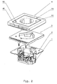
- such an electrical installation device of building system technology consists mainly of a base part 1, a fixable on the base part 1 support ring 2, a fixed to the support ring 2 and the base part 1 lighting device 3, and a design part 4 and in FIG. 2 and FIG. 3 darg Popeen closer, arranged in the base part 1, necessary for the function contact parts.
- the lighting device 3 is constructed in a modular manner and consists of a with a plurality of light sources 5 and a light sensor 50 fitted circuit board 6, which is received by a lower housing part 7 and covered by a housing upper part 8.
- the lighting device 3 thus represents an independently handleable, protected by its own housing module.
- Two trained as contact springs 9 contact elements provide the electrically conductive connection between the circuit board 6 and the light sources 5 and the light sensor 50 and the necessary contact function parts of the base part. 1 ago.
- the two contact springs 9 come into contact with their one end area contact-making conductor tracks of the printed circuit board 6 and with its other end portion contact-making in each case at an associated contact part of the base part 1 to the plant, in FIG. 2 and FIG.
- the two contact springs 9 are each formed as helical compression springs, so that the necessary for a secure contact contact pressure is readily established.
- Isolierstoffdome 10 are integrally formed on the outer wall of the lower housing part.
- the lighting means 5 of the lighting device 3 are each formed as an LED.
- the necessary for the function of contact parts of the base part 1 are on the one hand designed as spring terminals and provided depending on the design of the electrical installation device to z. B. the connection of the electrical lines and / or on the other hand, the contact receiving of connector pins z. B. to be introduced electrical safety plug (see in particular FIG. 2 ) to give contact.
- these contact parts can be designed as switch contact parts just as well.
- the lower housing part 7 of the lighting device 3 is provided at one of its design part 4 associated narrow sides with an elongated slot for the passage of the light emitted by the bulbs 5 light.
- the lighting device 3 is associated with this slot on the existing design part 4 light guide so that the light emitted by the bulbs 5 light is desired radiated into the environment.
- the design part 4 has a cylindrically shaped light sensor cover 60, which is received in a form-fitting manner by a circular opening formed in the design part 4 and assigned to the light sensor 50 arranged on the circuit board 6 of the lighting device 3.
- the light sensor 50 serves to enable the lighting device 3 to be switched on or off automatically depending on the intensity of the ambient light.
- the fixed to the base part 1 support ring 2 is made of metal and provides for the lighting device 3 is a stable edition possibility.
- the design part 4 integrally has a cover frame 4a and a cover center piece 4b. In order for the accommodation of the lighting device 3 enough space between the top of the support ring 2 and the bottom of the design part 4 is created, this has corresponding dimensions.
- the base part 1 is part of an orientation light and has according to its functions, the necessary functional components.
- the design part 4 integrally has a cover frame 4a and a socket center piece 4c. In order for the accommodation of the lighting device 3 enough space between the top of the support ring 2 and the bottom of the design part 4 is created, this has corresponding dimensions.
- the base part 1 is part of a socket outlet and has according to its functions, the necessary functional components.
- this has a frame-shaped design with an opening provided at a central point.
- the breakthrough is therefore at least slightly larger than is necessary for the passage of a conventional pot of a socket center piece 4c.
Landscapes
- Engineering & Computer Science (AREA)
- Microelectronics & Electronic Packaging (AREA)
- Non-Portable Lighting Devices Or Systems Thereof (AREA)
- Arrangement Of Elements, Cooling, Sealing, Or The Like Of Lighting Devices (AREA)
Claims (15)
- Appareil d'installation électrique relevant des installations techniques systémiques des bâtiments et de la domotique, comportant un cache design, et comportant un élément socle (1) muni d'un anneau support (2), élément socle permettant la connexion électrique au système d'installation du bâtiment, et auquel est raccordé de plus un dispositif d'éclairage (3) présentant au moins une ampoule (5), le dispositif d'éclairage (3) présentant une carte à circuits imprimés (6) munie de cette ampoule (5) au moins existante, carte à circuits imprimés reliée par l'intermédiaire de deux ressorts de contact (9) aux éléments de contact situés dans l'élément socle (1) de telle sorte qu'il y a passage de courant, caractérisé en ce que une cavité d'accueil est prévue pour l'agencement pour le dispositif d'éclairage (3), cavité donnée entre la partie supérieure de l'anneau support (2) et la partie inférieure d'un élément design (4), et en ce que la carte à circuits imprimés (6) du dispositif d'éclairage (3) est accueillie par une partie inférieure de boîtier (7) recouverte par une partie supérieure de boîtier (8), et en ce que la partie inférieure de boîtier (7) du dispositif d'éclairage (3) est munie sur au moins un de ses côtés étroits attribués à l'élément design (4) d'une fente pour le passage de la lumière produite par les ampoules (5), et en ce que le dispositif d'éclairage (3) est attribué par au moins une fente à au moins un élément de guidage de la lumière (40) existant sur l'élément design (4) de telle sorte que la lumière produite par les ampoules (5) soit émise vers l'extérieur par cet élément de guidage de la lumière (40) au moins existant.
- Appareil d'installation électrique selon la revendication 1, caractérisé en ce que au moins une ampoule (5) du dispositif d'éclairage (3) est réalisée sous forme de LED.
- Appareil d'installation électrique selon l'une des revendications 1 ou 2,
caractérisé en ce que au moins une ampoule (5) du dispositif d'éclairage (3) est réalisée sous forme de OLED, - Appareil d'installation électrique selon l'une des revendications 1 à 3,
caractérisé en ce que au moins une ampoule (5) du dispositif d'éclairage (3) est attribuée à au moins un élément de guidage de la lumière (40). - Appareil d'installation électrique selon l'une des revendications 1 à 4,
caractérisé en ce que au moins un élément de guidage de la lumière est donné dans l'élément design (4). - Appareil d'installation électrique selon l'une des revendications 1 à 5,
caractérisé en ce que l'anneau support (2) est au moins en partie en plastique. - Appareil d'installation électrique selon l'une des revendications 1 à 6,
caractérisé en ce que l'anneau support (2) est au moins en partie en métal. - Appareil d'installation électrique selon l'une des revendications 1 à 7,
caractérisé en ce que l'élément design (4) présente en une pièce un cadre cache (4a) et une pièce centrale cache (4b). - Appareil d'installation électrique selon l'une des revendications 1 à 7,
caractérisé en ce que l'élément design (4) présente en une pièce un cadre cache (4a) et une pièce centrale de prise femelle (4c). - Appareil d'installation électrique selon l'une des revendications 1 à 9,
caractérisé en ce que l'élément design (4) est prévu pour accueillir au moins un élément d'actionnement. - Appareil d'installation électrique selon l'une des revendications 1 à 10,
caractérisé en ce que l'élément socle (1) fait partie d'une lampe d'orientation. - Appareil d'installation électrique selon l'une des revendications 1 à 10,
caractérisé en ce que l'élément socle (1) fait partie d'une prise de courant femelle à contact de protection prise de terre. - Appareil d'installation électrique selon l'une des revendications 1 à 10,
caractérisé en ce que l'élément socle (1) fait partie d'un appareil de commutation. - Appareil d'installation électrique selon l'une des revendications 1 à 13,
caractérisé en ce que le dispositif d'éclairage (3) est formé sous forme de cadre. - Appareil d'installation électrique selon l'une des revendications 1 à 14,
caractérisé en ce que au moins un capteur de lumière (50) est placé sur la carte à circuits imprimés (6) du dispositif d'éclairage (3).
Priority Applications (1)
| Application Number | Priority Date | Filing Date | Title |
|---|---|---|---|
| PL10157341T PL2429044T3 (pl) | 2009-07-03 | 2010-03-23 | Elektryczne urządzenie instalacyjne |
Applications Claiming Priority (1)
| Application Number | Priority Date | Filing Date | Title |
|---|---|---|---|
| DE102009031586A DE102009031586B3 (de) | 2009-07-03 | 2009-07-03 | Elektrisches Installationsgerät |
Publications (2)
| Publication Number | Publication Date |
|---|---|
| EP2429044A1 EP2429044A1 (fr) | 2012-03-14 |
| EP2429044B1 true EP2429044B1 (fr) | 2014-01-01 |
Family
ID=43308017
Family Applications (1)
| Application Number | Title | Priority Date | Filing Date |
|---|---|---|---|
| EP10157341.8A Active EP2429044B1 (fr) | 2009-07-03 | 2010-03-23 | Appareil d'installation électrique |
Country Status (3)
| Country | Link |
|---|---|
| EP (1) | EP2429044B1 (fr) |
| DE (1) | DE102009031586B3 (fr) |
| PL (1) | PL2429044T3 (fr) |
Families Citing this family (5)
| Publication number | Priority date | Publication date | Assignee | Title |
|---|---|---|---|---|
| DE102011054266B3 (de) | 2011-10-07 | 2012-11-29 | Berker Gmbh & Co. Kg | Elektrische Schutzkontaktsteckdose |
| DE102016111957B4 (de) | 2016-06-30 | 2018-07-19 | Albrecht Jung Gmbh & Co. Kg | Elektrisches/elektronisches Gerät |
| DE102016111956B3 (de) * | 2016-06-30 | 2017-06-14 | Albrecht Jung Gmbh & Co. Kg | Elektrisches/elektronisches Gerät |
| CN105932479B (zh) * | 2016-07-07 | 2018-01-05 | 温州国好机电科技有限公司 | 一种透水防潮安全插座 |
| DE102018106105A1 (de) * | 2018-03-15 | 2019-09-19 | Berker Gmbh & Co. Kg | Elektronikmodul für ein elektrisches Installationsgerät |
Family Cites Families (5)
| Publication number | Priority date | Publication date | Assignee | Title |
|---|---|---|---|---|
| DE20019668U1 (de) * | 2000-11-20 | 2001-01-25 | Lee, Chien-Yu, Hsintien, Taipeh | Nachtleuchte zur Kombination mit einem Schalter |
| DE10233331C1 (de) | 2002-07-23 | 2003-11-20 | Berker Gmbh & Co Kg | Elektrisches Schaltgerät |
| DE10334247B3 (de) | 2003-07-28 | 2004-11-11 | Berker Gmbh & Co. Kg | Elektrische Schutzkontaktsteckdose |
| DE102006017915B3 (de) * | 2006-04-18 | 2007-08-02 | Albrecht Jung Gmbh & Co. Kg | Elektrisches/elektronisches Installationsgerät |
| DE102007046818B4 (de) * | 2007-09-29 | 2018-01-25 | Elso Gmbh | Elektrische Steckdose |
-
2009
- 2009-07-03 DE DE102009031586A patent/DE102009031586B3/de not_active Expired - Fee Related
-
2010
- 2010-03-23 PL PL10157341T patent/PL2429044T3/pl unknown
- 2010-03-23 EP EP10157341.8A patent/EP2429044B1/fr active Active
Also Published As
| Publication number | Publication date |
|---|---|
| DE102009031586B3 (de) | 2011-01-13 |
| EP2429044A1 (fr) | 2012-03-14 |
| PL2429044T3 (pl) | 2014-05-30 |
Similar Documents
| Publication | Publication Date | Title |
|---|---|---|
| DE102007001850B3 (de) | Installationsschalter oder -taster mit Beleuchtung und Baukastensystem zur Bildung eines Installationsschalters oder -tasters mit Beleuchtung | |
| EP3114403B1 (fr) | Luminaire comprenant des modules lumineux interchangeables | |
| EP1983620B1 (fr) | Prise électrique dotée d'un éclairage d'orientation | |
| EP2429044B1 (fr) | Appareil d'installation électrique | |
| EP2348522B1 (fr) | Bouton ou interrupteur d'installation doté d'une bascule ayant une sortie de lumière pour un éclairage | |
| EP2579398B1 (fr) | Prise électrique à contact protégé | |
| AT14620U1 (de) | Leuchte mit Trägerelement und lösbar befestigbarem Leuchtmodul | |
| DE102007046818B4 (de) | Elektrische Steckdose | |
| EP3527886B1 (fr) | Dispositif comprenant un appareil d'instalation électrique/ électronique et un luminiare électrique | |
| DE10113240A1 (de) | Multifunktionsleuchte | |
| DE102009031588B4 (de) | Elektrische Steckvorrichtung | |
| EP2040278A2 (fr) | Commutateur électrique | |
| EP2508796A2 (fr) | Dispositif d'éclairage | |
| EP3751680A1 (fr) | Prise de courant de sécurité commutable à distance | |
| EP3879547B1 (fr) | Appareil d'installation électrique à éclairage intégré | |
| EP1988615B1 (fr) | Prise électrique encastrée dotée d'un module de moyen d'éclairage | |
| EP2348248B1 (fr) | Lampe à DEL encastrée dotée d'un plateau de support | |
| DE102013102598B3 (de) | Elektrisches/elektronisches Installationsgerät | |
| DE102018103381B3 (de) | Elektrische Leuchte | |
| DE102018103375B3 (de) | Elektrische Leuchte | |
| DE102012101111B4 (de) | Leuchteneinheit | |
| DE102016111956B3 (de) | Elektrisches/elektronisches Gerät | |
| EP3396234A1 (fr) | Dispositif d'éclairage | |
| DE202012104882U1 (de) | Beleuchtungsanordnung zum Beleuchten des Innenraumes eines Windkraftanlagenturmes | |
| EP3540886A1 (fr) | Module électronique pour appareil d'installation électrique |
Legal Events
| Date | Code | Title | Description |
|---|---|---|---|
| AK | Designated contracting states |
Kind code of ref document: A1 Designated state(s): AT BE BG CH CY CZ DE DK EE ES FI FR GB GR HR HU IE IS IT LI LT LU LV MC MK MT NL NO PL PT RO SE SI SK SM TR |
|
| AX | Request for extension of the european patent |
Extension state: AL BA ME RS |
|
| PUAI | Public reference made under article 153(3) epc to a published international application that has entered the european phase |
Free format text: ORIGINAL CODE: 0009012 |
|
| 17P | Request for examination filed |
Effective date: 20120403 |
|
| GRAP | Despatch of communication of intention to grant a patent |
Free format text: ORIGINAL CODE: EPIDOSNIGR1 |
|
| GRAS | Grant fee paid |
Free format text: ORIGINAL CODE: EPIDOSNIGR3 |
|
| INTG | Intention to grant announced |
Effective date: 20131017 |
|
| GRAA | (expected) grant |
Free format text: ORIGINAL CODE: 0009210 |
|
| AK | Designated contracting states |
Kind code of ref document: B1 Designated state(s): AT BE BG CH CY CZ DE DK EE ES FI FR GB GR HR HU IE IS IT LI LT LU LV MC MK MT NL NO PL PT RO SE SI SK SM TR |
|
| REG | Reference to a national code |
Ref country code: GB Ref legal event code: FG4D Free format text: NOT ENGLISH |
|
| REG | Reference to a national code |
Ref country code: CH Ref legal event code: EP |
|
| REG | Reference to a national code |
Ref country code: IE Ref legal event code: FG4D Free format text: LANGUAGE OF EP DOCUMENT: GERMAN |
|
| REG | Reference to a national code |
Ref country code: DE Ref legal event code: R096 Ref document number: 502010005813 Country of ref document: DE Effective date: 20140213 |
|
| REG | Reference to a national code |
Ref country code: AT Ref legal event code: REF Ref document number: 647953 Country of ref document: AT Kind code of ref document: T Effective date: 20140215 |
|
| REG | Reference to a national code |
Ref country code: NL Ref legal event code: VDEP Effective date: 20140101 |
|
| REG | Reference to a national code |
Ref country code: PL Ref legal event code: T3 |
|
| REG | Reference to a national code |
Ref country code: LT Ref legal event code: MG4D |
|
| PG25 | Lapsed in a contracting state [announced via postgrant information from national office to epo] |
Ref country code: LT Free format text: LAPSE BECAUSE OF FAILURE TO SUBMIT A TRANSLATION OF THE DESCRIPTION OR TO PAY THE FEE WITHIN THE PRESCRIBED TIME-LIMIT Effective date: 20140101 Ref country code: IS Free format text: LAPSE BECAUSE OF FAILURE TO SUBMIT A TRANSLATION OF THE DESCRIPTION OR TO PAY THE FEE WITHIN THE PRESCRIBED TIME-LIMIT Effective date: 20140501 |
|
| PG25 | Lapsed in a contracting state [announced via postgrant information from national office to epo] |
Ref country code: ES Free format text: LAPSE BECAUSE OF FAILURE TO SUBMIT A TRANSLATION OF THE DESCRIPTION OR TO PAY THE FEE WITHIN THE PRESCRIBED TIME-LIMIT Effective date: 20140101 Ref country code: SE Free format text: LAPSE BECAUSE OF FAILURE TO SUBMIT A TRANSLATION OF THE DESCRIPTION OR TO PAY THE FEE WITHIN THE PRESCRIBED TIME-LIMIT Effective date: 20140101 Ref country code: CY Free format text: LAPSE BECAUSE OF FAILURE TO SUBMIT A TRANSLATION OF THE DESCRIPTION OR TO PAY THE FEE WITHIN THE PRESCRIBED TIME-LIMIT Effective date: 20140101 Ref country code: PT Free format text: LAPSE BECAUSE OF FAILURE TO SUBMIT A TRANSLATION OF THE DESCRIPTION OR TO PAY THE FEE WITHIN THE PRESCRIBED TIME-LIMIT Effective date: 20140502 Ref country code: NL Free format text: LAPSE BECAUSE OF FAILURE TO SUBMIT A TRANSLATION OF THE DESCRIPTION OR TO PAY THE FEE WITHIN THE PRESCRIBED TIME-LIMIT Effective date: 20140101 Ref country code: FI Free format text: LAPSE BECAUSE OF FAILURE TO SUBMIT A TRANSLATION OF THE DESCRIPTION OR TO PAY THE FEE WITHIN THE PRESCRIBED TIME-LIMIT Effective date: 20140101 |
|
| PG25 | Lapsed in a contracting state [announced via postgrant information from national office to epo] |
Ref country code: LV Free format text: LAPSE BECAUSE OF FAILURE TO SUBMIT A TRANSLATION OF THE DESCRIPTION OR TO PAY THE FEE WITHIN THE PRESCRIBED TIME-LIMIT Effective date: 20140101 Ref country code: HR Free format text: LAPSE BECAUSE OF FAILURE TO SUBMIT A TRANSLATION OF THE DESCRIPTION OR TO PAY THE FEE WITHIN THE PRESCRIBED TIME-LIMIT Effective date: 20140101 |
|
| REG | Reference to a national code |
Ref country code: DE Ref legal event code: R097 Ref document number: 502010005813 Country of ref document: DE |
|
| PG25 | Lapsed in a contracting state [announced via postgrant information from national office to epo] |
Ref country code: DK Free format text: LAPSE BECAUSE OF FAILURE TO SUBMIT A TRANSLATION OF THE DESCRIPTION OR TO PAY THE FEE WITHIN THE PRESCRIBED TIME-LIMIT Effective date: 20140101 Ref country code: CZ Free format text: LAPSE BECAUSE OF FAILURE TO SUBMIT A TRANSLATION OF THE DESCRIPTION OR TO PAY THE FEE WITHIN THE PRESCRIBED TIME-LIMIT Effective date: 20140101 Ref country code: EE Free format text: LAPSE BECAUSE OF FAILURE TO SUBMIT A TRANSLATION OF THE DESCRIPTION OR TO PAY THE FEE WITHIN THE PRESCRIBED TIME-LIMIT Effective date: 20140101 Ref country code: LU Free format text: LAPSE BECAUSE OF FAILURE TO SUBMIT A TRANSLATION OF THE DESCRIPTION OR TO PAY THE FEE WITHIN THE PRESCRIBED TIME-LIMIT Effective date: 20140323 Ref country code: RO Free format text: LAPSE BECAUSE OF FAILURE TO SUBMIT A TRANSLATION OF THE DESCRIPTION OR TO PAY THE FEE WITHIN THE PRESCRIBED TIME-LIMIT Effective date: 20140101 |
|
| REG | Reference to a national code |
Ref country code: CH Ref legal event code: PL |
|
| PLBE | No opposition filed within time limit |
Free format text: ORIGINAL CODE: 0009261 |
|
| STAA | Information on the status of an ep patent application or granted ep patent |
Free format text: STATUS: NO OPPOSITION FILED WITHIN TIME LIMIT |
|
| PG25 | Lapsed in a contracting state [announced via postgrant information from national office to epo] |
Ref country code: SK Free format text: LAPSE BECAUSE OF FAILURE TO SUBMIT A TRANSLATION OF THE DESCRIPTION OR TO PAY THE FEE WITHIN THE PRESCRIBED TIME-LIMIT Effective date: 20140101 |
|
| 26N | No opposition filed |
Effective date: 20141002 |
|
| REG | Reference to a national code |
Ref country code: IE Ref legal event code: MM4A |
|
| REG | Reference to a national code |
Ref country code: DE Ref legal event code: R097 Ref document number: 502010005813 Country of ref document: DE Effective date: 20141002 |
|
| PG25 | Lapsed in a contracting state [announced via postgrant information from national office to epo] |
Ref country code: IE Free format text: LAPSE BECAUSE OF NON-PAYMENT OF DUE FEES Effective date: 20140323 Ref country code: CH Free format text: LAPSE BECAUSE OF NON-PAYMENT OF DUE FEES Effective date: 20140331 Ref country code: LI Free format text: LAPSE BECAUSE OF NON-PAYMENT OF DUE FEES Effective date: 20140331 |
|
| PG25 | Lapsed in a contracting state [announced via postgrant information from national office to epo] |
Ref country code: SI Free format text: LAPSE BECAUSE OF FAILURE TO SUBMIT A TRANSLATION OF THE DESCRIPTION OR TO PAY THE FEE WITHIN THE PRESCRIBED TIME-LIMIT Effective date: 20140101 |
|
| REG | Reference to a national code |
Ref country code: FR Ref legal event code: PLFP Year of fee payment: 7 |
|
| PG25 | Lapsed in a contracting state [announced via postgrant information from national office to epo] |
Ref country code: MT Free format text: LAPSE BECAUSE OF FAILURE TO SUBMIT A TRANSLATION OF THE DESCRIPTION OR TO PAY THE FEE WITHIN THE PRESCRIBED TIME-LIMIT Effective date: 20140101 |
|
| PG25 | Lapsed in a contracting state [announced via postgrant information from national office to epo] |
Ref country code: SM Free format text: LAPSE BECAUSE OF FAILURE TO SUBMIT A TRANSLATION OF THE DESCRIPTION OR TO PAY THE FEE WITHIN THE PRESCRIBED TIME-LIMIT Effective date: 20140101 Ref country code: NO Free format text: LAPSE BECAUSE OF FAILURE TO SUBMIT A TRANSLATION OF THE DESCRIPTION OR TO PAY THE FEE WITHIN THE PRESCRIBED TIME-LIMIT Effective date: 20140401 |
|
| PG25 | Lapsed in a contracting state [announced via postgrant information from national office to epo] |
Ref country code: MC Free format text: LAPSE BECAUSE OF FAILURE TO SUBMIT A TRANSLATION OF THE DESCRIPTION OR TO PAY THE FEE WITHIN THE PRESCRIBED TIME-LIMIT Effective date: 20140101 |
|
| PG25 | Lapsed in a contracting state [announced via postgrant information from national office to epo] |
Ref country code: GR Free format text: LAPSE BECAUSE OF FAILURE TO SUBMIT A TRANSLATION OF THE DESCRIPTION OR TO PAY THE FEE WITHIN THE PRESCRIBED TIME-LIMIT Effective date: 20140402 Ref country code: BG Free format text: LAPSE BECAUSE OF FAILURE TO SUBMIT A TRANSLATION OF THE DESCRIPTION OR TO PAY THE FEE WITHIN THE PRESCRIBED TIME-LIMIT Effective date: 20140101 |
|
| PG25 | Lapsed in a contracting state [announced via postgrant information from national office to epo] |
Ref country code: BE Free format text: LAPSE BECAUSE OF FAILURE TO SUBMIT A TRANSLATION OF THE DESCRIPTION OR TO PAY THE FEE WITHIN THE PRESCRIBED TIME-LIMIT Effective date: 20140331 Ref country code: TR Free format text: LAPSE BECAUSE OF FAILURE TO SUBMIT A TRANSLATION OF THE DESCRIPTION OR TO PAY THE FEE WITHIN THE PRESCRIBED TIME-LIMIT Effective date: 20140101 Ref country code: HU Free format text: LAPSE BECAUSE OF FAILURE TO SUBMIT A TRANSLATION OF THE DESCRIPTION OR TO PAY THE FEE WITHIN THE PRESCRIBED TIME-LIMIT; INVALID AB INITIO Effective date: 20100323 |
|
| REG | Reference to a national code |
Ref country code: FR Ref legal event code: PLFP Year of fee payment: 8 |
|
| REG | Reference to a national code |
Ref country code: FR Ref legal event code: PLFP Year of fee payment: 9 |
|
| PG25 | Lapsed in a contracting state [announced via postgrant information from national office to epo] |
Ref country code: MK Free format text: LAPSE BECAUSE OF FAILURE TO SUBMIT A TRANSLATION OF THE DESCRIPTION OR TO PAY THE FEE WITHIN THE PRESCRIBED TIME-LIMIT Effective date: 20140101 |
|
| P01 | Opt-out of the competence of the unified patent court (upc) registered |
Effective date: 20230606 |
|
| PGFP | Annual fee paid to national office [announced via postgrant information from national office to epo] |
Ref country code: AT Payment date: 20240304 Year of fee payment: 15 |
|
| PGFP | Annual fee paid to national office [announced via postgrant information from national office to epo] |
Ref country code: GB Payment date: 20240327 Year of fee payment: 15 |
|
| PGFP | Annual fee paid to national office [announced via postgrant information from national office to epo] |
Ref country code: PL Payment date: 20240301 Year of fee payment: 15 Ref country code: IT Payment date: 20240321 Year of fee payment: 15 |
|
| REG | Reference to a national code |
Ref country code: AT Ref legal event code: MM01 Ref document number: 647953 Country of ref document: AT Kind code of ref document: T Effective date: 20250323 |
|
| GBPC | Gb: european patent ceased through non-payment of renewal fee |
Effective date: 20250323 |
|
| PG25 | Lapsed in a contracting state [announced via postgrant information from national office to epo] |
Ref country code: GB Free format text: LAPSE BECAUSE OF NON-PAYMENT OF DUE FEES Effective date: 20250323 |
|
| PG25 | Lapsed in a contracting state [announced via postgrant information from national office to epo] |
Ref country code: AT Free format text: LAPSE BECAUSE OF NON-PAYMENT OF DUE FEES Effective date: 20250323 |
|
| PG25 | Lapsed in a contracting state [announced via postgrant information from national office to epo] |
Ref country code: IT Free format text: LAPSE BECAUSE OF NON-PAYMENT OF DUE FEES Effective date: 20250323 |
|
| PGFP | Annual fee paid to national office [announced via postgrant information from national office to epo] |
Ref country code: DE Payment date: 20260327 Year of fee payment: 17 |
|
| PGFP | Annual fee paid to national office [announced via postgrant information from national office to epo] |
Ref country code: FR Payment date: 20260325 Year of fee payment: 17 |