EP2429265A2 - Procédé et dispositif de communication par un câble électrique - Google Patents
Procédé et dispositif de communication par un câble électrique Download PDFInfo
- Publication number
- EP2429265A2 EP2429265A2 EP11005127A EP11005127A EP2429265A2 EP 2429265 A2 EP2429265 A2 EP 2429265A2 EP 11005127 A EP11005127 A EP 11005127A EP 11005127 A EP11005127 A EP 11005127A EP 2429265 A2 EP2429265 A2 EP 2429265A2
- Authority
- EP
- European Patent Office
- Prior art keywords
- load
- communication
- current
- time window
- line
- Prior art date
- Legal status (The legal status is an assumption and is not a legal conclusion. Google has not performed a legal analysis and makes no representation as to the accuracy of the status listed.)
- Withdrawn
Links
Images



Classifications
-
- H—ELECTRICITY
- H04—ELECTRIC COMMUNICATION TECHNIQUE
- H04B—TRANSMISSION
- H04B3/00—Line transmission systems
- H04B3/54—Systems for transmission via power distribution lines
- H04B3/544—Setting up communications; Call and signalling arrangements
-
- H—ELECTRICITY
- H05—ELECTRIC TECHNIQUES NOT OTHERWISE PROVIDED FOR
- H05B—ELECTRIC HEATING; ELECTRIC LIGHT SOURCES NOT OTHERWISE PROVIDED FOR; CIRCUIT ARRANGEMENTS FOR ELECTRIC LIGHT SOURCES, IN GENERAL
- H05B47/00—Circuit arrangements for operating light sources in general, i.e. where the type of light source is not relevant
- H05B47/10—Controlling the light source
- H05B47/175—Controlling the light source by remote control
- H05B47/198—Grouping of control procedures or address assignation to light sources
-
- H—ELECTRICITY
- H05—ELECTRIC TECHNIQUES NOT OTHERWISE PROVIDED FOR
- H05B—ELECTRIC HEATING; ELECTRIC LIGHT SOURCES NOT OTHERWISE PROVIDED FOR; CIRCUIT ARRANGEMENTS FOR ELECTRIC LIGHT SOURCES, IN GENERAL
- H05B47/00—Circuit arrangements for operating light sources in general, i.e. where the type of light source is not relevant
- H05B47/10—Controlling the light source
- H05B47/175—Controlling the light source by remote control
- H05B47/185—Controlling the light source by remote control via power line carrier transmission
-
- H—ELECTRICITY
- H04—ELECTRIC COMMUNICATION TECHNIQUE
- H04B—TRANSMISSION
- H04B2203/00—Indexing scheme relating to line transmission systems
- H04B2203/54—Aspects of powerline communications not already covered by H04B3/54 and its subgroups
- H04B2203/5404—Methods of transmitting or receiving signals via power distribution lines
- H04B2203/5412—Methods of transmitting or receiving signals via power distribution lines by modofying wave form of the power source
Definitions
- the present invention relates to communication systems that include a controller that communicates with one or more load modules via a load line for electrical energy transfer.
- the invention further relates to a control device and a load module for such a communication system.
- the invention further relates to methods of communication between a controller and one or more load modules.
- a typical application is for example the lighting control, in which the light intensity of several lamps is to be set individually.
- the load modules next to the respective lighting element it is necessary for the load modules next to the respective lighting element to have power controllers which communicate with the common control unit via a predefined protocol.
- LED lamps already include power controllers that provide power to the LED using pulse width modulation. By controlling the duty cycle of the pulse width modulation, it is possible to vary the light intensity of the LED lamps. Further, the communication channel between the control unit and the power controller integrated with the load module may also be used to transmit a feedback that could allow for more efficient use of electrical energy, actual load monitoring, and higher reliability.
- load modules that the consumer of the load modules to be addressed individually addressed or controlled. This requires a recognition method by which the individual load modules inform the control unit of their presence and by which a logical address can be assigned to the load modules. This requires bidirectional communication.
- the load modules require an information channel to the controller to determine their status, e.g. For diagnostic and measurement purposes, to communicate or to acknowledge critical commands from the control unit.
- KNX KNX power line modem
- the Patent DE 101 63 957 A1 describes an electronic add-on module for fluorescent lamps, which can be addressed by a control unit. It is also mentioned that color and brightness information is transmitted via the power line.
- the control unit is connected to the phase conductor and the neutral and the addresses of the electronic modules on the lamps must be preset by means of mechanical switches.
- Patent US 6,867,558 B2 relates to the possibility of controlling a group of lamps via a power line without requiring rewiring with respect to conventional lighting systems.
- the controller and the one or more load modules may each comprise a power modem, wherein each power modem is disabled during the power transmission time window so that it has substantially no conductivity, and during the communication time window, either for receiving in a "listen” state is offset, in which the impedance of the current-level device is set so that the communication current is limited to a predetermined maximum current value, or is placed in a "Talk” state in which the impedance of the current-level device is variable so that to send one to transmitting information on the load line of the communication current between a predetermined first current value and a predetermined second current value changes.
- the communication system may be configured to perform bidirectional communication only between the controller and one of the one or more load modules.
- the controller and the one or more load modules may be configured to detect a collision due to concurrent transmission of information to be transmitted at the protocol level during address allocation and / or frequency modulation application based on signal waveform distortion or overshoot of the maximum Current value to recognize by the current on the load line.
- the communication time window corresponds to a time window in which the mains voltage is greater in magnitude than a first threshold value and smaller in magnitude than a second threshold value
- the energy transmission time window corresponds to a time window in which the mains voltage is greater in magnitude than the second threshold
- the method may provide for the controller and the one or more load modules to be placed in a "listen" state during the communication window for either receiving data by adjusting the impedance of the current modem so that the communication current is at a high level predetermined maximum current value, or be put into a "Talk” state in which the impedance of the current-level device is variable so that to transmit information to be transmitted on the load line, the communication current between a predetermined first current value and a predetermined second current value ,
- an address mapping may be performed by the controller sending a request to request an address through the one or more load modules, the load modules sending a random identification code to the controller after a random number of communication time windows, and the controller one having a logical address and sends information provided to the random identification code, so that its logical address is assigned to the relevant load module on the basis of the sent random identification code.
- Bi-directional communication is enabled between the controller and the load modules over a single line by modulating the current flowing on that line.
- An additional control line is not required.
- the individual load modules can be controlled independently of each other and under specification of different requirements (eg with regard to brightness and / or color in the case of illumination) by the control unit.
- feedback from the load modules to the controller is possible. Since the modulation takes place only on the load line between the controller and the load modules, other consumers of the house installation thereof are affected in any way.
- the load modules 3 are connected in parallel with each other between a load line L 'and a neutral conductor N of the power line 4.
- the control unit 2 is connected in series between phase conductor L and load line L '.
- L 'thus designates the switched / controlled section of the phase conductor designated as load line between the control unit 2 and the load modules 3.
- the communication between the controller 2 and the load modules 3 is z. B. according to a half-duplex method, d. H. a communication is only possible in one direction and can only be carried out with the participation of the control unit 2. Furthermore, the transmission of electrical energy to the load modules 3 and the communication of data between the controller 2 and the load modules 3 are performed in different time windows.
- the supply block 24 is used to remove the phase conductor L, if necessary, electrical energy, inter alia, for operating the microprocessor 21, the current sensor 22 and the circuit breaker 23.
- the supply block 24 is driven by the microprocessor 21, so that the phase conductor L is only taken electrical energy, if this is predetermined by the microprocessor 21. Otherwise should the supply block 24, at least during communication between the control unit 2 and load module 3, remain in a high impedance state.
- the current indicator 22 serves to monitor the current in the current path and to set a desired impedance so that the communication described below becomes possible.
- the power modem 22 of the controller 2 is connected in the current path between phase conductor L and load line L 'and serves to control and monitor the current level in the load line L'.
- data bits are modulated by adjusting the impedance of the current modem 22, the current being varied during a communication phase in the range between a minimum current value I min and a maximum current value I maX .
- the current modem 22 may receive data or information.
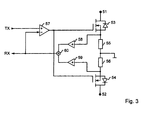
- FIG. 3 is a more detailed representation of the current model 22 and 32 shown.
- the power modem 22, 32 is connected in series in the corresponding power line or load line and has a first terminal 51 for connection to the phase conductor L respectively with the load line L 'and a second terminal 52 for connection to the load line L' respectively with the neutral conductor N of Power line 4 on.
- a first power switch eg a first n-channel enhancement mode MOSFET 53
- a second power switch eg a second enhancement type n-channel MOSFET 54
- a first sense resistor 55 and a second sense resistor 56 are provided in series with the MOSFETs 53, 54.
- the RX signal RX is used as a feedback signal in a control loop which controls the control voltage of the MOSFETs 53, 54. In this way, the Current in the current channel to be set by the current model to a value that is proportional to the TX signal TX.
- FIG. 4 a signal-time diagram is shown, which represents the separation between signal and energy transmission in energy transmission time window EF and communication time window KF.
- the upper sinusoidal curve indicates the course of the mains voltage U between the phase conductor L and the neutral conductor N of the power line 4.
- the periodic curve of the voltage is divided into successive time windows, namely into the energy transmission time window EF, in which electrical energy is transmitted, and into the communication time window KF, in which a signal transmission takes place for communication between the control device 2 and the load modules 3.
- the communication time window KF is defined with respect to the voltage profile and is located in areas in which the magnitude of the voltage is less than a first predetermined threshold value U S1 and greater than a second predetermined threshold value U S2 .
- the energy transfer time window EF is defined with respect to the voltage profile and is located in regions in which the magnitude of the voltage is greater than the second predetermined threshold value U S2 .
- angular ranges ⁇ 2 , 180 ° - ⁇ 2 ; 180 ° + ⁇ 2 , 360 ° - ⁇ 2 defined.
- the first threshold value U S1 preferably corresponds to the voltage of a voltage between 30% and 70% of the peak value of the mains voltage, preferably a voltage between 40% and 60% of the peak value, such as 50%.
- the second threshold value U S2 of the voltage preferably corresponds to a voltage between 5% and 25% of the peak value of the mains voltage, in particular between 10% and 20% of the peak value of the mains voltage, eg 15%.
- the energy transmission time window In principle, provision should be made for the energy transmission time window to extend beyond the peak value of the course of the network voltage.
- Alternative to the above symmetrical arrangement of the energy transfer time window can also be provided asymmetrical arrangements of the energy transfer time window with respect to the peak value of the mains voltage.
- a synchronization time window SYNC is provided which divides two of the communication time windows KF.
- the synchronization time window SYNC is not for transmitting information between the controller 2 and the load modules 3 because the available voltage for providing the maximum current value I max on the load line L 'and for transmitting electrical power to the load 34 is too low. In this case, all the current modules 22, 32 of the controller 2 and the load modules 3 are in a passive "list" state.
- the zero crossing of the mains voltage can be detected in a suitable manner by the microprocessors 21, 31 in order to synchronize the internal timers of the microprocessor with respect to the mains frequency of the power network.
- the detection can be carried out by means of a suitable voltmeter and / or by means of the sensing resistors 55, 56 of the current-carrying device 22, 32.
- the supply block 24 and the power block 33 should continue to be deactivated during the synchronization phase and the power switch 23 should also be open or high impedance, since during the zero crossing no energy can be transmitted to the load 34 to a significant extent.
- the communication begins again in a further communication time window, wherein the power switch 23 remains open.
- the communication is terminated and the energy transmission phase of the energy transmission time window begins.
- All of the current sensors 22, 32 are turned off under the control of the synchronized microprocessors 21, 31, and the power switch 23 is closed to transfer electrical energy to the load modules 3 during the energy transfer time window.
- the Power block 33 is activated by the microprocessors 21, 31 and begins to branch off electrical energy in the form of a supply current for the corresponding load 34.
- Fig. 4 1 shows the magnitude current values of the supply current during the energy transfer time window and the current values of the communication current which change between two current values I max , I min for transferring digital information, the signs of which depend in each case on whether the Mains voltage is positive or negative.
- the power switch 23 After a certain period of time after the zero crossing, in particular after exceeding a maximum or minimum of the amplitude of the mains voltage, the power switch 23 is opened again and the communication is recorded in the subsequent communication time window KF.
- the power switch 23 is opened again and the communication is recorded in the subsequent communication time window KF.
- the communication is based z. B., as described above, on a current modulation and is basically capable of multiple load modules 3 to operate.
- the increased demands on the communication method are that the load modules 3 are connected in parallel with each other between load line L 'and neutral N of the power line 4 and must be connected in series with the control unit 2. This is determined by the available line infrastructure, for example in buildings.
- the controller 2 may communicate as "master" information to all the load modules 3 as "slaves" by setting the total current in the Circuit between a minimum current value I min and a maximum current value I max is modulated.
- each load module 3 can contribute only to a small degree to the power in the line network, in particular with a larger number of load modules 3. For this reason, the communication method provides that only one device 2, 3 can transmit simultaneously. Furthermore, it should be provided that, when a load module 3 transmits, the other load modules 3 disconnect their current modules 32 from the load line L ', ie switch them into the off state or switch them to high impedance. In order to avoid a conflict of the data transmission on the load line L ', a load module 3 should only transmit if this has been expressly requested by the control unit 2.
- the microprocessor 21, 31 places the respective current modem 21, 31 in a "list” state.
- the TX signal TX is used to limit the current in the current mode current path to the predetermined maximum current value I max .
- the TX signal TX is a voltage signal from the microprocessor 31 predetermined and formed by the difference formation with the RX signal RX a control.
- the TX signal TX corresponds to a voltage whose voltage value corresponds to the voltage drop across the sensing resistors 55, 56, when it flows through a current having the maximum current value I max .
- the microprocessors 31 of the load modules 3 drive their current modules 32 to limit the current flow through each of the current modules 32 to the maximum current value I max .
- a synchronization of the microprocessors 21, 31 is fixed and the number n of the connected load modules has been estimated.
- the communication is now carried out according to the above procedure only within the communication time window KF.
- all load modules 3 remain in the "list” state and the controller 3 may start transmitting data according to a "talk" state.
- the "Talk" state provides that the TX signal TX is used to utilize the current of the phase in the entire range between the minimum current value I min and the maximum current value I max for data transmission.
- the current can be monitored to detect a collision. A collision is detected when the current value corresponding to the RX signal RX exceeds the maximum current value I max .
- step S6 As soon as the connected load modules 3 receive an ID_request command from the control unit 2, in step S6 it generates a temporary identifier, for example randomly or depending on the serial number of the respective load module 3. This temporary identifier is read by each of the load modules 3 in step S6 random number of communication time windows KF transmitted to the control unit 2.
- the controller 2 decodes erroneous information. In this case, error detection methods are used. For example, the controller 2 may be configured to recognize that the checksum is incorrect, whereupon the controller 2 discards the received message. As long as the load modules 3 do not receive responses within a predetermined time, they repeat the transmission of the temporary identifier each time after a random number of communication time windows KF.
- the temporary identifier may be in the form of a bit sequence of sufficient length, e.g. 16 bit, 24 bit or 32 bit.
- amplitude modulation is described above by way of example and in detail, it will be understood that frequency modulation may be used as well.
- frequency modulation may be used as well.
- any, generally known types of modulation can be used.
Landscapes
- Engineering & Computer Science (AREA)
- Power Engineering (AREA)
- Computer Networks & Wireless Communication (AREA)
- Signal Processing (AREA)
- Cable Transmission Systems, Equalization Of Radio And Reduction Of Echo (AREA)
- Selective Calling Equipment (AREA)
Applications Claiming Priority (2)
| Application Number | Priority Date | Filing Date | Title |
|---|---|---|---|
| DE102010032395 | 2010-07-27 | ||
| DE102010034347A DE102010034347A1 (de) | 2010-07-27 | 2010-08-14 | Verfahren und Vorrichtung zur Kommunikation über eine Lastleitung |
Publications (2)
| Publication Number | Publication Date |
|---|---|
| EP2429265A2 true EP2429265A2 (fr) | 2012-03-14 |
| EP2429265A3 EP2429265A3 (fr) | 2012-07-11 |
Family
ID=45471018
Family Applications (1)
| Application Number | Title | Priority Date | Filing Date |
|---|---|---|---|
| EP11005127A Withdrawn EP2429265A3 (fr) | 2010-07-27 | 2011-06-24 | Procédé et dispositif de communication par un câble électrique |
Country Status (4)
| Country | Link |
|---|---|
| EP (1) | EP2429265A3 (fr) |
| CN (1) | CN102377456A (fr) |
| DE (1) | DE102010034347A1 (fr) |
| RU (1) | RU2011131290A (fr) |
Cited By (1)
| Publication number | Priority date | Publication date | Assignee | Title |
|---|---|---|---|---|
| CN111697568A (zh) * | 2020-05-23 | 2020-09-22 | 浙江巨磁智能技术有限公司 | 一种集成于acdc电源模组的功率信息传递方法 |
Families Citing this family (7)
| Publication number | Priority date | Publication date | Assignee | Title |
|---|---|---|---|---|
| PT3005516T (pt) * | 2013-07-25 | 2021-01-26 | Siemens Ag | Método e dispositivo para sinalização e controlo de uma rede elétrica que acopla uma pluralidade de atuadores |
| FR3046493B1 (fr) * | 2015-12-31 | 2018-07-27 | Aledia | Circuit optoelectronique a diodes electroluminescentes |
| EP3293845A1 (fr) * | 2016-09-08 | 2018-03-14 | Alcatel Lucent | Disjoncteur pour communication par ligne électrique |
| DE102016118085A1 (de) * | 2016-09-26 | 2018-03-29 | Osram Gmbh | Verfahren und sensorvorrichtung zur steuerung einer beleuchtungseinrichtung in einem beleuchtungssystem sowie beleuchtungssystem hierzu |
| CN106338645B (zh) * | 2016-11-09 | 2019-06-04 | 广州视源电子科技股份有限公司 | 一种变频器的电流采样装置及其方法 |
| CN108964718B (zh) * | 2018-08-03 | 2022-05-03 | 深圳市磊芯半导体有限公司 | 双向信号传输系统及其设备管理方法 |
| CN119078689B (zh) * | 2024-10-15 | 2025-09-30 | 广汽本田汽车有限公司 | 一种车载设备系统和汽车 |
Citations (8)
| Publication number | Priority date | Publication date | Assignee | Title |
|---|---|---|---|---|
| DE19603680C1 (de) | 1996-02-02 | 1997-08-28 | Eugen Ringwald | Verfahren zum selektiven Schalten und Steuern von Verbrauchern in einem Wechselstromkreis |
| US6211624B1 (en) | 1996-08-09 | 2001-04-03 | Walter Holzer | Method and device for the modulation of the intensity of fluorescent lamps |
| US6225759B1 (en) | 1998-01-20 | 2001-05-01 | Lumion Corporation | Method and apparatus for controlling lights |
| DE10163957A1 (de) | 2001-12-23 | 2003-07-03 | Der Kluth Decke Und Licht Gmbh | Elektronisches Vorschaltgerät |
| US6867558B2 (en) | 2003-05-12 | 2005-03-15 | General Electric Company | Method and apparatus for networked lighting system control |
| US7265654B1 (en) | 2004-04-22 | 2007-09-04 | Powerline Control Systems, Inc. | Powerline pulse position modulated transmitter apparatus and method |
| US20090027175A1 (en) | 2004-09-29 | 2009-01-29 | Aizo Ag | Data Transmission Method and Device for A/C Systems |
| WO2009133489A1 (fr) | 2008-04-30 | 2009-11-05 | Koninklijke Philips Electronics N.V. | Procédés et appareil pour encoder des informations sur une tension de ligne alternative |
Family Cites Families (5)
| Publication number | Priority date | Publication date | Assignee | Title |
|---|---|---|---|---|
| US5471119A (en) * | 1994-06-08 | 1995-11-28 | Mti International, Inc. | Distributed control system for lighting with intelligent electronic ballasts |
| GB2335334B (en) * | 1998-03-13 | 2001-03-28 | And Software Ltd | Apparatus for and method of transmitting and receiving data over a low voltage power distribution system |
| DE102004026468A1 (de) * | 2004-05-29 | 2005-12-22 | Daimlerchrysler Ag | Datenübertragung auf Stromversorgungsleitungen |
| DE102004055933A1 (de) * | 2004-11-19 | 2006-05-24 | Patent-Treuhand-Gesellschaft für elektrische Glühlampen mbH | Verfahren zur Vergabe von Kurzadressen in Beleuchtungsanlagen |
| IL192462A0 (en) * | 2008-06-26 | 2009-02-11 | B S N Pro Ltd | Electrical device control |
-
2010
- 2010-08-14 DE DE102010034347A patent/DE102010034347A1/de not_active Ceased
-
2011
- 2011-06-24 EP EP11005127A patent/EP2429265A3/fr not_active Withdrawn
- 2011-07-26 RU RU2011131290/08A patent/RU2011131290A/ru not_active Application Discontinuation
- 2011-07-26 CN CN2011102204349A patent/CN102377456A/zh active Pending
Patent Citations (8)
| Publication number | Priority date | Publication date | Assignee | Title |
|---|---|---|---|---|
| DE19603680C1 (de) | 1996-02-02 | 1997-08-28 | Eugen Ringwald | Verfahren zum selektiven Schalten und Steuern von Verbrauchern in einem Wechselstromkreis |
| US6211624B1 (en) | 1996-08-09 | 2001-04-03 | Walter Holzer | Method and device for the modulation of the intensity of fluorescent lamps |
| US6225759B1 (en) | 1998-01-20 | 2001-05-01 | Lumion Corporation | Method and apparatus for controlling lights |
| DE10163957A1 (de) | 2001-12-23 | 2003-07-03 | Der Kluth Decke Und Licht Gmbh | Elektronisches Vorschaltgerät |
| US6867558B2 (en) | 2003-05-12 | 2005-03-15 | General Electric Company | Method and apparatus for networked lighting system control |
| US7265654B1 (en) | 2004-04-22 | 2007-09-04 | Powerline Control Systems, Inc. | Powerline pulse position modulated transmitter apparatus and method |
| US20090027175A1 (en) | 2004-09-29 | 2009-01-29 | Aizo Ag | Data Transmission Method and Device for A/C Systems |
| WO2009133489A1 (fr) | 2008-04-30 | 2009-11-05 | Koninklijke Philips Electronics N.V. | Procédés et appareil pour encoder des informations sur une tension de ligne alternative |
Cited By (1)
| Publication number | Priority date | Publication date | Assignee | Title |
|---|---|---|---|---|
| CN111697568A (zh) * | 2020-05-23 | 2020-09-22 | 浙江巨磁智能技术有限公司 | 一种集成于acdc电源模组的功率信息传递方法 |
Also Published As
| Publication number | Publication date |
|---|---|
| RU2011131290A (ru) | 2013-02-10 |
| DE102010034347A1 (de) | 2012-02-02 |
| CN102377456A (zh) | 2012-03-14 |
| EP2429265A3 (fr) | 2012-07-11 |
Similar Documents
| Publication | Publication Date | Title |
|---|---|---|
| EP2429265A2 (fr) | Procédé et dispositif de communication par un câble électrique | |
| DE60118777T2 (de) | Protokollverbesserung für beleuchtungssteuernetze und kommunikationsschnittstelle hierfür | |
| DE102009051968B4 (de) | Verfahren zur Übertragung einer Steuerinformation von einem Steuergerät zu einer Lampeneinheit, ein dafür geeignetes Beleuchtungssystem, sowie Lampeneinheit | |
| EP2288238B1 (fr) | Commande des dispositifs d'éclairage par des signaux modulés sur bus à courant continu | |
| EP2554021B1 (fr) | Branche émettrice de tension de réseau d'une interface d'un appareil de commande pour moyen d'éclairage | |
| DE102013001194A1 (de) | LED-Modul. LED-Vorschaltvorrichtung und System aus einem LED-Modul und einer LED-Vorschaltvorrichtung | |
| DE112011101245B4 (de) | Betriebsgerät für Leuchtmittel zum Ermitteln eines Energie- oder Leistungsverbrauchs und Verfahren zum Erfassen desselbigen | |
| EP1794895B1 (fr) | Procede et systeme de transmission de donnees pour reseaux a tension alternative | |
| EP1675274B1 (fr) | Procédé de transmission de données sur une ligne de puissance à courant alternatif | |
| DE102018205590B4 (de) | LEISTUNGSVERSORGUNGSVORRICHTUNG UND KOMMUNIKATIONSSYSTEM FÜR BELEUCHTUNGSSYSTEME MIT DERSELBEN, SOWIE vERFAHREN ZUR SPANNUNGSVERSORGUNG EINER ELEKTRISCHEN LAST | |
| DE102010052661B3 (de) | Kommunikationssystem zur Steuerung von elektrischen Lasten | |
| DE102010064027B4 (de) | Schnittstelle mit Potentialtrennglied im Empfangszweig | |
| EP3123828B1 (fr) | Appareil de service d'éléments luminescents pour le transfert d'informations | |
| DE102010052662B4 (de) | Datentelegramm-Generierungsverfahren zur Ansteuerung mindestens eines Lastmoduls bzw. einer Lampe über eine Lastleitung | |
| WO2010043263A1 (fr) | Dispositif d’interface pour un circuit de commande de lumière dali et procédé pour sa surveillance | |
| EP2486774A1 (fr) | Interface pour appareil destiné à faire fonctionner un moyen d'éclairage | |
| EP3672375B1 (fr) | Variateur de luminosité | |
| DE102017126742B4 (de) | Schaltungsanordnung mit einem Betriebsschaltkreis sowie Verfahren zur Programmierung oder Aktualisierung wenigstens eines Betriebskennwerts des Betriebsschaltkreises | |
| DE102013201588A1 (de) | Verfahren zur Übermittlung von Datensignalen, Leuchte, Versorgungsgerät und System zur Beleuchtung | |
| DE202005011950U1 (de) | Elektronisches Lampenvorschaltgerät mit Bereitstellung einer DC-Busversorgungsspannung für ein Lichtsteuersystem | |
| EP3123821A1 (fr) | Circuit d'alimentation en tension pour faire fonctionner des led | |
| DE102019103889A1 (de) | Ein- und Auskoppelung von Daten und Datentransport über elektrische Versorgungsleitung von Beleuchtungssystemen | |
| AT508809A1 (de) | Schnittstelle für ein betriebsgerät für leuchtmittel | |
| EP3689112B1 (fr) | Possibilité de signalisation étendue dans un système dali | |
| EP3664304A1 (fr) | Entrée et sortie de données et transport de données par l'intermédiaire d'une conduite d'alimentation électrique des systèmes d'éclairage |
Legal Events
| Date | Code | Title | Description |
|---|---|---|---|
| AK | Designated contracting states |
Kind code of ref document: A2 Designated state(s): AL AT BE BG CH CY CZ DE DK EE ES FI FR GB GR HR HU IE IS IT LI LT LU LV MC MK MT NL NO PL PT RO RS SE SI SK SM TR |
|
| AX | Request for extension of the european patent |
Extension state: BA ME |
|
| PUAI | Public reference made under article 153(3) epc to a published international application that has entered the european phase |
Free format text: ORIGINAL CODE: 0009012 |
|
| PUAL | Search report despatched |
Free format text: ORIGINAL CODE: 0009013 |
|
| AK | Designated contracting states |
Kind code of ref document: A3 Designated state(s): AL AT BE BG CH CY CZ DE DK EE ES FI FR GB GR HR HU IE IS IT LI LT LU LV MC MK MT NL NO PL PT RO RS SE SI SK SM TR |
|
| AX | Request for extension of the european patent |
Extension state: BA ME |
|
| RIC1 | Information provided on ipc code assigned before grant |
Ipc: H04B 3/54 20060101ALI20120605BHEP Ipc: H05B 37/02 20060101AFI20120605BHEP |
|
| STAA | Information on the status of an ep patent application or granted ep patent |
Free format text: STATUS: THE APPLICATION IS DEEMED TO BE WITHDRAWN |
|
| 18D | Application deemed to be withdrawn |
Effective date: 20130112 |