EP2429687B1 - Procédé de traitement biologique de déchets organiques et installation utilisant ce procédé - Google Patents
Procédé de traitement biologique de déchets organiques et installation utilisant ce procédé Download PDFInfo
- Publication number
- EP2429687B1 EP2429687B1 EP10730839.7A EP10730839A EP2429687B1 EP 2429687 B1 EP2429687 B1 EP 2429687B1 EP 10730839 A EP10730839 A EP 10730839A EP 2429687 B1 EP2429687 B1 EP 2429687B1
- Authority
- EP
- European Patent Office
- Prior art keywords
- phase
- gas
- liquid
- reactor
- liquid contactor
- Prior art date
- Legal status (The legal status is an assumption and is not a legal conclusion. Google has not performed a legal analysis and makes no representation as to the accuracy of the status listed.)
- Active
Links
Images


Classifications
-
- B—PERFORMING OPERATIONS; TRANSPORTING
- B01—PHYSICAL OR CHEMICAL PROCESSES OR APPARATUS IN GENERAL
- B01D—SEPARATION
- B01D61/00—Processes of separation using semi-permeable membranes, e.g. dialysis, osmosis or ultrafiltration; Apparatus, accessories or auxiliary operations specially adapted therefor
- B01D61/14—Ultrafiltration; Microfiltration
- B01D61/147—Microfiltration
-
- C—CHEMISTRY; METALLURGY
- C02—TREATMENT OF WATER, WASTE WATER, SEWAGE, OR SLUDGE
- C02F—TREATMENT OF WATER, WASTE WATER, SEWAGE, OR SLUDGE
- C02F3/00—Biological treatment of water, waste water, or sewage
- C02F3/30—Aerobic and anaerobic processes
-
- B—PERFORMING OPERATIONS; TRANSPORTING
- B01—PHYSICAL OR CHEMICAL PROCESSES OR APPARATUS IN GENERAL
- B01D—SEPARATION
- B01D53/00—Separation of gases or vapours; Recovering vapours of volatile solvents from gases; Chemical or biological purification of waste gases, e.g. engine exhaust gases, smoke, fumes, flue gases, aerosols
- B01D53/34—Chemical or biological purification of waste gases
- B01D53/46—Removing components of defined structure
- B01D53/54—Nitrogen compounds
- B01D53/58—Ammonia
-
- B—PERFORMING OPERATIONS; TRANSPORTING
- B01—PHYSICAL OR CHEMICAL PROCESSES OR APPARATUS IN GENERAL
- B01D—SEPARATION
- B01D53/00—Separation of gases or vapours; Recovering vapours of volatile solvents from gases; Chemical or biological purification of waste gases, e.g. engine exhaust gases, smoke, fumes, flue gases, aerosols
- B01D53/34—Chemical or biological purification of waste gases
- B01D53/46—Removing components of defined structure
- B01D53/62—Carbon oxides
-
- B—PERFORMING OPERATIONS; TRANSPORTING
- B01—PHYSICAL OR CHEMICAL PROCESSES OR APPARATUS IN GENERAL
- B01D—SEPARATION
- B01D53/00—Separation of gases or vapours; Recovering vapours of volatile solvents from gases; Chemical or biological purification of waste gases, e.g. engine exhaust gases, smoke, fumes, flue gases, aerosols
- B01D53/34—Chemical or biological purification of waste gases
- B01D53/74—General processes for purification of waste gases; Apparatus or devices specially adapted therefor
- B01D53/77—Liquid phase processes
- B01D53/78—Liquid phase processes with gas-liquid contact
-
- C—CHEMISTRY; METALLURGY
- C02—TREATMENT OF WATER, WASTE WATER, SEWAGE, OR SLUDGE
- C02F—TREATMENT OF WATER, WASTE WATER, SEWAGE, OR SLUDGE
- C02F3/00—Biological treatment of water, waste water, or sewage
- C02F3/02—Aerobic processes
- C02F3/12—Activated sludge processes
-
- C—CHEMISTRY; METALLURGY
- C02—TREATMENT OF WATER, WASTE WATER, SEWAGE, OR SLUDGE
- C02F—TREATMENT OF WATER, WASTE WATER, SEWAGE, OR SLUDGE
- C02F3/00—Biological treatment of water, waste water, or sewage
- C02F3/02—Aerobic processes
- C02F3/12—Activated sludge processes
- C02F3/1236—Particular type of activated sludge installations
- C02F3/1268—Membrane bioreactor systems
-
- C—CHEMISTRY; METALLURGY
- C02—TREATMENT OF WATER, WASTE WATER, SEWAGE, OR SLUDGE
- C02F—TREATMENT OF WATER, WASTE WATER, SEWAGE, OR SLUDGE
- C02F3/00—Biological treatment of water, waste water, or sewage
- C02F3/30—Aerobic and anaerobic processes
- C02F3/308—Biological phosphorus removal
-
- C—CHEMISTRY; METALLURGY
- C05—FERTILISERS; MANUFACTURE THEREOF
- C05B—PHOSPHATIC FERTILISERS
- C05B9/00—Fertilisers based essentially on phosphates or double phosphates of magnesium
-
- C—CHEMISTRY; METALLURGY
- C05—FERTILISERS; MANUFACTURE THEREOF
- C05F—ORGANIC FERTILISERS NOT COVERED BY SUBCLASSES C05B, C05C, e.g. FERTILISERS FROM WASTE OR REFUSE
- C05F17/00—Preparation of fertilisers characterised by biological or biochemical treatment steps, e.g. composting or fermentation
- C05F17/10—Addition or removal of substances other than water or air to or from the material during the treatment
- C05F17/15—Addition or removal of substances other than water or air to or from the material during the treatment the material being gas
-
- C—CHEMISTRY; METALLURGY
- C05—FERTILISERS; MANUFACTURE THEREOF
- C05F—ORGANIC FERTILISERS NOT COVERED BY SUBCLASSES C05B, C05C, e.g. FERTILISERS FROM WASTE OR REFUSE
- C05F17/00—Preparation of fertilisers characterised by biological or biochemical treatment steps, e.g. composting or fermentation
- C05F17/50—Treatments combining two or more different biological or biochemical treatments, e.g. anaerobic and aerobic treatment or vermicomposting and aerobic treatment
-
- C—CHEMISTRY; METALLURGY
- C12—BIOCHEMISTRY; BEER; SPIRITS; WINE; VINEGAR; MICROBIOLOGY; ENZYMOLOGY; MUTATION OR GENETIC ENGINEERING
- C12M—APPARATUS FOR ENZYMOLOGY OR MICROBIOLOGY; APPARATUS FOR CULTURING MICROORGANISMS FOR PRODUCING BIOMASS, FOR GROWING CELLS OR FOR OBTAINING FERMENTATION OR METABOLIC PRODUCTS, i.e. BIOREACTORS OR FERMENTERS
- C12M47/00—Means for after-treatment of the produced biomass or of the fermentation or metabolic products, e.g. storage of biomass
- C12M47/18—Gas cleaning, e.g. scrubbers; Separation of different gases
-
- B—PERFORMING OPERATIONS; TRANSPORTING
- B01—PHYSICAL OR CHEMICAL PROCESSES OR APPARATUS IN GENERAL
- B01D—SEPARATION
- B01D2251/00—Reactants
- B01D2251/40—Alkaline earth metal or magnesium compounds
- B01D2251/402—Alkaline earth metal or magnesium compounds of magnesium
-
- B—PERFORMING OPERATIONS; TRANSPORTING
- B01—PHYSICAL OR CHEMICAL PROCESSES OR APPARATUS IN GENERAL
- B01D—SEPARATION
- B01D2251/00—Reactants
- B01D2251/60—Inorganic bases or salts
- B01D2251/606—Carbonates
-
- B—PERFORMING OPERATIONS; TRANSPORTING
- B01—PHYSICAL OR CHEMICAL PROCESSES OR APPARATUS IN GENERAL
- B01D—SEPARATION
- B01D2257/00—Components to be removed
- B01D2257/40—Nitrogen compounds
- B01D2257/406—Ammonia
-
- B—PERFORMING OPERATIONS; TRANSPORTING
- B01—PHYSICAL OR CHEMICAL PROCESSES OR APPARATUS IN GENERAL
- B01D—SEPARATION
- B01D2257/00—Components to be removed
- B01D2257/50—Carbon oxides
- B01D2257/504—Carbon dioxide
-
- B—PERFORMING OPERATIONS; TRANSPORTING
- B01—PHYSICAL OR CHEMICAL PROCESSES OR APPARATUS IN GENERAL
- B01D—SEPARATION
- B01D2258/00—Sources of waste gases
- B01D2258/05—Biogas
-
- C—CHEMISTRY; METALLURGY
- C02—TREATMENT OF WATER, WASTE WATER, SEWAGE, OR SLUDGE
- C02F—TREATMENT OF WATER, WASTE WATER, SEWAGE, OR SLUDGE
- C02F2103/00—Nature of the water, waste water, sewage or sludge to be treated
- C02F2103/002—Grey water, e.g. from clothes washers, showers or dishwashers
-
- C—CHEMISTRY; METALLURGY
- C02—TREATMENT OF WATER, WASTE WATER, SEWAGE, OR SLUDGE
- C02F—TREATMENT OF WATER, WASTE WATER, SEWAGE, OR SLUDGE
- C02F2103/00—Nature of the water, waste water, sewage or sludge to be treated
- C02F2103/20—Nature of the water, waste water, sewage or sludge to be treated from animal husbandry
-
- C—CHEMISTRY; METALLURGY
- C02—TREATMENT OF WATER, WASTE WATER, SEWAGE, OR SLUDGE
- C02F—TREATMENT OF WATER, WASTE WATER, SEWAGE, OR SLUDGE
- C02F2103/00—Nature of the water, waste water, sewage or sludge to be treated
- C02F2103/32—Nature of the water, waste water, sewage or sludge to be treated from the food or foodstuff industry, e.g. brewery waste waters
-
- C—CHEMISTRY; METALLURGY
- C02—TREATMENT OF WATER, WASTE WATER, SEWAGE, OR SLUDGE
- C02F—TREATMENT OF WATER, WASTE WATER, SEWAGE, OR SLUDGE
- C02F2209/00—Controlling or monitoring parameters in water treatment
- C02F2209/02—Temperature
-
- C—CHEMISTRY; METALLURGY
- C02—TREATMENT OF WATER, WASTE WATER, SEWAGE, OR SLUDGE
- C02F—TREATMENT OF WATER, WASTE WATER, SEWAGE, OR SLUDGE
- C02F2209/00—Controlling or monitoring parameters in water treatment
- C02F2209/06—Controlling or monitoring parameters in water treatment pH
-
- C—CHEMISTRY; METALLURGY
- C02—TREATMENT OF WATER, WASTE WATER, SEWAGE, OR SLUDGE
- C02F—TREATMENT OF WATER, WASTE WATER, SEWAGE, OR SLUDGE
- C02F2209/00—Controlling or monitoring parameters in water treatment
- C02F2209/14—NH3-N
-
- C—CHEMISTRY; METALLURGY
- C02—TREATMENT OF WATER, WASTE WATER, SEWAGE, OR SLUDGE
- C02F—TREATMENT OF WATER, WASTE WATER, SEWAGE, OR SLUDGE
- C02F2209/00—Controlling or monitoring parameters in water treatment
- C02F2209/22—O2
-
- C—CHEMISTRY; METALLURGY
- C02—TREATMENT OF WATER, WASTE WATER, SEWAGE, OR SLUDGE
- C02F—TREATMENT OF WATER, WASTE WATER, SEWAGE, OR SLUDGE
- C02F2209/00—Controlling or monitoring parameters in water treatment
- C02F2209/42—Liquid level
-
- Y—GENERAL TAGGING OF NEW TECHNOLOGICAL DEVELOPMENTS; GENERAL TAGGING OF CROSS-SECTIONAL TECHNOLOGIES SPANNING OVER SEVERAL SECTIONS OF THE IPC; TECHNICAL SUBJECTS COVERED BY FORMER USPC CROSS-REFERENCE ART COLLECTIONS [XRACs] AND DIGESTS
- Y02—TECHNOLOGIES OR APPLICATIONS FOR MITIGATION OR ADAPTATION AGAINST CLIMATE CHANGE
- Y02C—CAPTURE, STORAGE, SEQUESTRATION OR DISPOSAL OF GREENHOUSE GASES [GHG]
- Y02C20/00—Capture or disposal of greenhouse gases
- Y02C20/40—Capture or disposal of greenhouse gases of CO2
-
- Y—GENERAL TAGGING OF NEW TECHNOLOGICAL DEVELOPMENTS; GENERAL TAGGING OF CROSS-SECTIONAL TECHNOLOGIES SPANNING OVER SEVERAL SECTIONS OF THE IPC; TECHNICAL SUBJECTS COVERED BY FORMER USPC CROSS-REFERENCE ART COLLECTIONS [XRACs] AND DIGESTS
- Y02—TECHNOLOGIES OR APPLICATIONS FOR MITIGATION OR ADAPTATION AGAINST CLIMATE CHANGE
- Y02E—REDUCTION OF GREENHOUSE GAS [GHG] EMISSIONS, RELATED TO ENERGY GENERATION, TRANSMISSION OR DISTRIBUTION
- Y02E50/00—Technologies for the production of fuel of non-fossil origin
- Y02E50/30—Fuel from waste, e.g. synthetic alcohol or diesel
-
- Y—GENERAL TAGGING OF NEW TECHNOLOGICAL DEVELOPMENTS; GENERAL TAGGING OF CROSS-SECTIONAL TECHNOLOGIES SPANNING OVER SEVERAL SECTIONS OF THE IPC; TECHNICAL SUBJECTS COVERED BY FORMER USPC CROSS-REFERENCE ART COLLECTIONS [XRACs] AND DIGESTS
- Y02—TECHNOLOGIES OR APPLICATIONS FOR MITIGATION OR ADAPTATION AGAINST CLIMATE CHANGE
- Y02P—CLIMATE CHANGE MITIGATION TECHNOLOGIES IN THE PRODUCTION OR PROCESSING OF GOODS
- Y02P20/00—Technologies relating to chemical industry
- Y02P20/141—Feedstock
- Y02P20/145—Feedstock the feedstock being materials of biological origin
-
- Y—GENERAL TAGGING OF NEW TECHNOLOGICAL DEVELOPMENTS; GENERAL TAGGING OF CROSS-SECTIONAL TECHNOLOGIES SPANNING OVER SEVERAL SECTIONS OF THE IPC; TECHNICAL SUBJECTS COVERED BY FORMER USPC CROSS-REFERENCE ART COLLECTIONS [XRACs] AND DIGESTS
- Y02—TECHNOLOGIES OR APPLICATIONS FOR MITIGATION OR ADAPTATION AGAINST CLIMATE CHANGE
- Y02P—CLIMATE CHANGE MITIGATION TECHNOLOGIES IN THE PRODUCTION OR PROCESSING OF GOODS
- Y02P20/00—Technologies relating to chemical industry
- Y02P20/151—Reduction of greenhouse gas [GHG] emissions, e.g. CO2
-
- Y—GENERAL TAGGING OF NEW TECHNOLOGICAL DEVELOPMENTS; GENERAL TAGGING OF CROSS-SECTIONAL TECHNOLOGIES SPANNING OVER SEVERAL SECTIONS OF THE IPC; TECHNICAL SUBJECTS COVERED BY FORMER USPC CROSS-REFERENCE ART COLLECTIONS [XRACs] AND DIGESTS
- Y02—TECHNOLOGIES OR APPLICATIONS FOR MITIGATION OR ADAPTATION AGAINST CLIMATE CHANGE
- Y02P—CLIMATE CHANGE MITIGATION TECHNOLOGIES IN THE PRODUCTION OR PROCESSING OF GOODS
- Y02P20/00—Technologies relating to chemical industry
- Y02P20/50—Improvements relating to the production of bulk chemicals
- Y02P20/59—Biological synthesis; Biological purification
-
- Y—GENERAL TAGGING OF NEW TECHNOLOGICAL DEVELOPMENTS; GENERAL TAGGING OF CROSS-SECTIONAL TECHNOLOGIES SPANNING OVER SEVERAL SECTIONS OF THE IPC; TECHNICAL SUBJECTS COVERED BY FORMER USPC CROSS-REFERENCE ART COLLECTIONS [XRACs] AND DIGESTS
- Y02—TECHNOLOGIES OR APPLICATIONS FOR MITIGATION OR ADAPTATION AGAINST CLIMATE CHANGE
- Y02W—CLIMATE CHANGE MITIGATION TECHNOLOGIES RELATED TO WASTEWATER TREATMENT OR WASTE MANAGEMENT
- Y02W10/00—Technologies for wastewater treatment
- Y02W10/10—Biological treatment of water, waste water, or sewage
-
- Y—GENERAL TAGGING OF NEW TECHNOLOGICAL DEVELOPMENTS; GENERAL TAGGING OF CROSS-SECTIONAL TECHNOLOGIES SPANNING OVER SEVERAL SECTIONS OF THE IPC; TECHNICAL SUBJECTS COVERED BY FORMER USPC CROSS-REFERENCE ART COLLECTIONS [XRACs] AND DIGESTS
- Y02—TECHNOLOGIES OR APPLICATIONS FOR MITIGATION OR ADAPTATION AGAINST CLIMATE CHANGE
- Y02W—CLIMATE CHANGE MITIGATION TECHNOLOGIES RELATED TO WASTEWATER TREATMENT OR WASTE MANAGEMENT
- Y02W30/00—Technologies for solid waste management
- Y02W30/40—Bio-organic fraction processing; Production of fertilisers from the organic fraction of waste or refuse
Definitions
- the present invention concerns a process for the biologic treatment of organic wastes, and in particular a biologic process for the reduction of the chemical oxygen demand (COD) and the mineralisation and recovery of the pollutants therein contained, in particular of carbon dioxide, nitrogen and phosphorus.
- COD chemical oxygen demand
- the invention also concerns a plant for the actuation of said process.
- cultivation conditions are defined aerobic when the tension of the oxygen dissolved in the culture (pO 2 ) is not below 5% of the saturation value in air at atmospheric pressure (oxygen sufficiency conditions).
- Cultivation conditions are defined microaerophilic when the tension of the oxygen dissolved in the culture (pO 2 ) is below 5% of the saturation value in air at atmospheric pressure, but the culture is not anaerobic since a continuous supply of oxygen to the culture is ensured even if the tension thereof in the liquid cannot be detected by the probe (oxygen limitation conditions).
- the zootechnic sector has recently become particularly critical, since the limiting factor for farm size is the availability of ground where to spread wastewaters, consisting mainly of animals' dejections. It is equally known that, on the other side, the profitability of the farming business requires that larger farms are preferred due to the evident economies of scale which can be obtained compared to small-sized ones. On the wave of this economic analysis particularly vast farms have hence been accomplished - in Europe pig farms provide up to 10,000 animals - with a resulting pressure on the ecosystem and relative problems particularly difficult to solve even in the short term. Therefore, various countries have preferred to legislate in the matter putting limitations to the amount of zootechnic wastes which may spread per year per surface unit.
- pig farms must meet legal requirements concerning the storing of dejections for a sufficient period of time between the end of a spreading season and the beginning of the subsequent one.
- Such storages normally consist of open tubs wherefrom the gases produced by the substantially anaerobic metabolism of the microorganisms found in the dejections are released in the atmosphere, generally obligate anaerobes, facultative anaerobes and archaebacteria such as methanogens. Since the gases released in the atmosphere comprise gases which contribute to the greenhouse effect, such as methane, carbon dioxide and ammonia, and toxic gases, such as hydrogen sulphide, it can be understood that the storage of wastes implies not irrelevant management problems. Moreover, following this degradation phase, nitrogen-containing substances are obtained, the release of which into the natural environment causes the eutrophication of water bodies and the increase of nitrate level in waters.
- CSTR Continuous Stirred Tank Reactor
- PFR piston-flow reactors
- FBR fluldised-bed reactors
- simple unstirred tubs Digestion is carried out most frequently In mesophilic conditions (30-40°C), more rarely in thermophilic conditions (50-60°C) or psychrophilic (10-20°C).
- the sedimentation tank necessary for this operation mode is a reactor which must be of a size proportioned to the residence time of the digester effluent necessary to obtain the desired sedimentation degree. Said residence time is therefore critically dependent on the sedimentability features of the solids, and consequently on the capacity of microbial populations to form relatively stable aggregates capable of sedimenting at appreciable speeds.
- EP 0 641 296 describes a degradation procedure of organic material which provides the organic material to alternately and periodically undergo mesophilic and thermophilic digestion.
- the organic material is at least partly digested with the simultaneous production of mesophilic and anaerobic biomass, while in the subsequent aerobic thermophilic or microaerophilic phase the residual organic material and the biomass of the mesophilic microorganisms coming from the previous phase are at least partly digested.
- Said cyclical treatment is carried out using the effluent of the aerobic bioreactor as supply for a second anaerobic reactor and so on for a series of reactors.
- JP9108672 describes an apparatus comprising an anaerobic sludge digesting chamber and an aerobic active sludge digesting chamber, the sludge in the anaerobic chamber being filtered and the filtrate being introduced in the aerobic chamber.
- Exhaust gases are not treated
- JP2002273489 describes a process in which an effluent is treated anaerobically so that biogas is produced. Ammonia is then stripped by steam from the effluent and the condensed steam comprising the ammonia is reacted with the biogas to form ammonium carbonate.
- a first object of the present invention is hence to accomplish a degradation process of organic substances which substantially reduces the polluting load, generating degradation products having low environmental impact, and a plant wherein such process can take place in a simple and effective manner.
- the chemical reduction with hydrogen which leads to the formation of ammonia is the base of the manufacture of nitrogen fertilisers containing ammonium salts and of nitrogen-containing ones, which are typically obtained from ammonia by catalytic oxidation with oxygen (Ostwald process).
- the nitrification/denitrification processes hence destroy a resource (ammonia) the regeneration of which for use in agriculture requires a considerable energy waste.
- about 80% of the ammonia produced, in the order of 150 million tons/year, is used in agriculture both in the form of ammonium salts and in the form of nitrates derived from said ammonia.
- US2007/0062231 A1 describes a method consisting in the heating of the ammonia-containing waste under partial vacuum and in the subsequent absorption of ammonia and of carbon dioxide released during the gaseous phase through a suspension of calcium sulphate; said sulphate is converted into calcium carbonate, which precipitates, and into ammonium sulphate in solution which is then recovered.
- a second object of the invention is hence to accomplish an innovative process for the mineralisation and the recovery of the nitrogen found in the by-products of the above described biological waste treatment process, playing on the action of the biological agents already present in the bioreactor, selected by the applied operation conditions, so as to obtain nitrogen in high-purity inorganic forms, virtually undistinguishable from those found in commercial chemical fertilisers, with the valuable additional benefit of a cost reduction of nitrogen fertilisation.
- Another object of the present invention is hence that of mineralising to the greatest possible extent the phosphorus found in the incoming slurry, converting it to the largest possible extent to a soluble inorganic form, such as orthophosphate, which can be treated and separated from the sludge with such a purity level to allow its direct further use, for example as fertiliser.
- a soluble inorganic form such as orthophosphate
- Another object again of the present invention is then that of accomplishing a reduction process of the CO 2 released during the above wastewater treatment process, to meet the requirements of greater attention to the release into the atmosphere of gases responsible for the greenhouse effect.
- the common problem of all wastewater anaerobic digestion systems is that of the partial removal of the polluting load, for example expressed as COD: as a matter of fact, at the moment, in the common anaerobic digesters operating on piggery wastes the residual COD values range between 35% and 70% of the value found in the incoming waste.
- the organic substance residues substantially consist in reluctant organic compounds and microbial biomass, which often cannot be released directly into the environment, with the need to carry out further treatments before the release of the effluents into the environment, with a rise of disposal costs and considerable logistic problems, which often cause a further rise of disposal costs.
- a further object of the present invention is hence to accomplish a waste treatment which allows to drastically reduce the COD and to make disposal procedures less complex.
- biodegradation plant of the invention will be made, for greater clarity, in connection with the path and the subsequent processing steps which the organic waste undergoes therethrough.
- a pipe 1 the flow rate of which is adjusted by a supply pump 2, carries the incoming slurry to an anaerobic digester 3, provided with a stirring system 4.
- the slurry is processed here a first time by means of a substantially conventional treatment for the methanogenic anaerobic digestion, wherein the degradation of part of the organic matter occurs with the resulting generation of a biogas flow 19.
- Digester 3 operates in a continuous mode, i.e. with the continuous or periodic release of fresh organic waste and the continuous or periodic removal of the digested contents.
- CSTR continuous digestion technique
- RFB repeated fed-batch technique
- the running temperature is maintained in the mesophilic range (30-40°C).
- the effluent is brought from the anaerobic digester 3 to a microfiltration apparatus or microfilter 7, through a conduit 5, the flow rate of which is adjusted by a second pump 6.
- Microfilter 7 acts so as to increase the concentration of suspended solids found in the slurry during the treatment in digester 3.
- microfilter 7 From microfilter 7, a flow of filtered substance substantially free from suspended solids comes out through a conduit 8, the flow of which is adjusted by a pump 9, to be sent to aerobic or microaerophilic bioreactor 10 for further treatment. At the same time, the solid substance which has been concentrated by filtration by microfilter 7 is instead sent back to digester 3 through a conduit 11, for it to be further treated according to the above described technique.
- Bioreactor 10 operates in thermophilic conditions (40-70°C) and in conditions of sufficient oxygen or of micro-aerophilicness. Such conditions, required for the correct operation of the bioreactor, are obtained by blowing into the bioreactor air or other oxygen-containing gas, through conduit 12, preferably together with mechanical stirring by propellers or turbines 13, so as to increase the oxygen decomposition speed.
- the tension of the oxygen dissolved in the liquid is measured by means of a conventional galvanometric or polarographic probe (not shown).
- Bioreactor 10 operates in a continuous mode with a scheme similar to the mesophilic anaerobic digester.
- a conduit 14 departs therefrom comprising a circulation pump 15 which leads the effluent of bioreactor 10 to a second microfiltration apparatus or microfilter 16.
- the solid substance which does not pass such microfilter is sent back - through a conduit 17 - to the same bioreactor 10, while the filtered fluids are brought outside this plant fraction through a conduit 18, for the possible subsequent use. Since the fluid coming out of conduit 18 is a clear solution, free from suspended solids, it is possible to provide - as an alternative to the traditional spreading thereof on fields - a further treatment of said liquid substance so as to turn it into a liquid fertiliser for commercial use.
- bioreactor 10 the flow of exhaust gas from slurry treatment is released - through an exit conduit 20 - substantially consisting of ammonia substances which prove useful subject to suitable treatment as described below.
- the optimal filling level of bioreactor 10 is controlled through a conduit 21 for the outflow of the digested fluid, adjusted by a drawing pump 22.
- the fluid coming out of conduit 21 is a suspension of solid substances, consisting in particular of microbial biomass and undigested, insoluble solids, and therefore it is normally used exclusively as dung to be spreaded on the ground.
- this flow is further treated - as described in detail in the following - to obtain full phosphate removal, so as to allow waste disposal into the water bodies without causing eutrophication phenomena in the same whatsoever.
- the process of the invention is hence particularly useful in all those cases in which the spreading of treated fluids across agricultural land is not possible, either because the farm does not have the necessary amount of land, or because the phosphate level in the same has already reached excessively high values.
- connection pipes of supply 23, the flow of which is adjusted by a pump 24, and of return 25, respectively, the flow of which is adjusted by a pump 26: the flow through conduit 23 is used - in a way known per se - to keep substantially constant the volume inside digester 3, while the flow through conduit 25 is adjusted so as to obtain the desired recycling intensity.
- the constancy of the above-said flows in time allows to maintain the entire plant in stationary operating conditions.
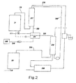
- the gaseous effluents of the first fraction are then treated so as to recover the nitrogen contained in the same and, in a preferred embodiment of the process of the invention, also the carbon dioxide found in the biogas of flow 19.
- This second plant fraction apt to further treat the exhaust gases rich in ammoniac substances coming out of exhaust gas conduit 20, schematically consists of a gas/liquid contactor 33, into the lower part of which said conduit leads, wherein the ammonia-containing gaseous phase is put in contact with an acidic solution fed in countercurrent through conduit 32.
- ammonia found in the gaseous phase dissolves into the liquid phase tending to establish a balance with the ammonia dissolved in the liquid. Said ammonia, in turn, establishes a balance with the ammonium ion in solution according to the following reaction: NH 3(gas) ⁇ NH 3 (aqueous) + H 2 O ⁇ NH 4 + + OH -
- sulphuric acid may be used and the addition of such acid to the liquid phase supplied to gas/liquid contactor 33 may be advantageously performed by means of an automatic titration apparatus, by which It is provided to keep the pH constant around a preset value, through a probe immersed in the liquid phase.
- the acid used is instead carbonic acid and such acid is obtained through the washing of the biogas produced by digester 3 through the liquid flow taken at the bottom of gas/liquid contactor 33, with the further advantage of recovering most of the CO 2 found in the biogas and hence substantially avoiding the release thereof into the atmosphere.
- conduit 19, which comes from bioreactor 3 supplies the biogas produced in said reactor to a gas/liquid contactor 27 where the biogas is treated in countercurrent through a liquid flow coming from tank 31 through conduit 32, contactor 33 and conduit 28'. Initially such flow consists of water into which hence the CO 2 contained in the biogas partly dissolves, until it reaches condition of equilibrium with carbonic acid which, partly dissociating, causes a drop of the pH of such liquid phase.
- the biogas thus poor in CO 2 , and hence consisting virtually entirely of methane, is extracted from contactor 27 through a conduit 28 and sent to a thermal motor/engine 29, which can be for example a burner, an internal combustion engine, or a turbine motor.
- a thermal motor/engine 29 which can be for example a burner, an internal combustion engine, or a turbine motor.
- the thermal or mechanical energy thus generated by the combustion of the biogas purified from CO 2 is favourably used for the internal requirements of the plant, thus improving the energy balance thereof, which the exhaust gases produced by such combustion are partly or fully supplied to the base of gas/liquid contactor 33 so that the CO 2 therein contained is absorbed into the liquid phase coming from tank 31, thus bringing a further acidity to the liquid flow of contactors 27 and 33.
- the acidic liquid phase coming out from contactor 27, through a conduit 30, also goes to feed a tank 31 which in turn replenishes - through a conduit 32 - gas/liquid contactor 33 for the treatment of the gaseous flow of ammonia-containing substances, a flow released by bioreactor 10.
- the ammonia-containing substances dissolve in the acidic liquid phase coming from tank 31 and their basicity is at least partly neutralised by the acidity introduced in the liquid phase by the CO 2 dissolved in contactor 27 and 33.
- the result of this neutralisation is the formation of a mixture of nitrogen salts (ammonium bicarbonate, ammonium carbonate, etc.) the equilibrium of which is influenced by the pH of the solution.
- a top-up water inflow conduit is provided as well as a conduit 34 for the outflow of the solution of nitrogen salts which is stored in a tank 36 for the subsequent stabilisation treatment.
- the stabilisation treatment of the mixture of nitrogen salts collected in tank 36 is performed in the third fraction of the plant, shown in fig. 3 .
- the stabilisation of such mixture is essential because otherwise it would tend to decompose also at relatively low temperatures, generating NH 3 and CO 2 gas and making it substantially impossible to preserve it for extended periods of time. It is then necessary to proceed to the transformation into nitrate ion of half (in molar terms) of the ammonium found int he solution coming from the system of combined contactor 27 and 33, so as to obtain an aqueous solution of ammonium nitrate (NH 4 NO 3 ), a substance having excellent fertilising characteristics, due both to the high percentage content of nitrogen (35% by weight) and of the stability thereof at the solid state or in solution.
- the transformation of part of the ammonium ion into nitrate ion occurs biologically through the so-called nitrification reaction, typical of consortiums of microorganisms belonging to the genera Nitrosomonas, Nitroso-coccus and Nitrobacter.
- the microorganisms belonging to the first two genera oxidise the ammonium ion to nitrite ion using molecular oxygen as electron acceptor, while those belonging to the third genera oxidise the nitrite ion to nitrate ion operating similarly, due to their autotrophy, i.e. their ability to use CO 2 as a source of carbon.
- the high concentration of CO 2 in the solution coming from the combined contactor system is hence particularly favourable for the development and the activity of these microorganisms for the purposes of the present invention.
- the partial nitrification of the ammonium ion is performed in a bioreactor, containing the nitrifying biomass in liquid suspension or adhered to a solid substrate, which is fed continuously or intermittently with the solution coming from the system of gas-liquid contactor, i.e. with the flow 34 shown in Fig. 2 .
- the chemical compounds necessary for the growth of the nitrifying microorganisms are fed to the system in the form of a suitable salts solution or more simply as fresh slurry added in a suitable amount to the solution of ammonia salts (34).
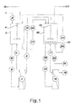
- Fig. 3 schematically shows such a nitrification system wherein the nitrifying biomass is contained in a bioreactor 35 consisting of a cylindrical container filled with a suitable material which retains the nitrifying biomass on its surface or within cavities of the material.
- the immobilised-biomass bioreactor is fed continuously or intermittently with the solution of ammonia salts 34 contained in a tank 36 into which it is poured through a pump 37 and from which it is drawn by a pump 38 which sends it to the head of bioreactor 35.
- the solution percolates through the bioreactor coming in contact with the nitrifying biomass contained therein and is hence collected again in tank 36.
- a continuous circulation of the solution of ammonia salts through bioreactor 35 is hence accomplished, which brings such salts continuously in contact with the nitrifying biomass and determines a progressive transformation of the ammonium ion into nitrate ion.
- bioreactor 35 is fed with air, or other oxygen-containing gas, which is delivered into the lower part (flow 39) and is released in the top part (flow 40).
- the progressive increase of the concentration of nitrate ions and the corresponding decrease of the concentration of ammonium ions in the liquid contained in container 36 can be controlled by continuously or periodically delivering a fresh solution of ammonia salts 34 through pump 37 and the simultaneous removal of nitrified solution by using a system for the automatic level control which keeps the volume constant by actuating a valve 41 for the outflow of a liquid flow from tank 36.
- a system for the automatic level control which keeps the volume constant by actuating a valve 41 for the outflow of a liquid flow from tank 36.
- the acidification of the effluent of aerobic reactor 10 allows the solubilisation of the phosphate-containing Insoluble compounds possibly present in reactor 10 due to the high pH value found therein. Such solubilisation is necessary to allow an efficient recovery of orthophosphate in clear effluent 45 produced by the microfiltration system 44 since any insoluble compounds would be retained by the filtering membrane.
- the precipitation of the orthophosphate found in clear effluent 45 is obtained by adding magnesium salts (for example MgCl 2 , MgSO 4 , MgO and the like) and the simultaneous alkalinisation of effluent 45.
- magnesium salts for example MgCl 2 , MgSO 4 , MgO and the like
- the use of MgO or of Mg(OH) 2 is particularly advantageous since It simultaneously determines the addition of magnesium ions and the alkalinisation of the solution.
- the simultaneous presence of ammonium and of orthophosphate In effluent 45 causes the addition of magnesium salts to determine the precipitation of the compound Mg(NH 4 )PO 4 (struvite), particularly advantageous In the application as fertiliser for agricultural uses. Said compound can be recovered through a filtration, sedimentation, centrifugation or other equivalent solid-liquid separation operation.
- microfiltration as a concentration method of suspended solids represents a remarkable improvement over the use of a sedimentation tank, since the efficiency of said tank crucially depends on the sedimentability characteristics of the suspended solids, which characteristics are hardly controllable by the operator.
- the above-described microfiltration apparatuses 7 and 16 advantageously reduce the complexity and the cost of manufacture and running the plant since it is no longer necessary - like in the known art - to provide within the plant the use of a sedimentation tank and furthermore to actuate all those technical devices necessary to obtain a high sedimentation capacity within reasonable times.
- the increase of the concentration of suspended solids in both bioreactors 3 and 10 which form part of the biodegradation plant subject of the present invention determines a remarkable increase of the overall degradation capacity, which In turn translates into a very pronounced decrease of the polluting load, as can be determined based on the overall reduction of the so-called volatile solids, essentially a measure of the organic substance found in the waste, or of the COD.
- contactor 33 preferably operates in a continuous mode, as Is clearly described in the final phase of the following example.
- the plant could operate also in a discontinuous mode using the same liquid phase until reaching the desired concentration of the ammonium salt.
- Operation conditions are chosen base on the desired recovery efficiency of ammonia gases and of the pH value of the contents of bioreactor 10, which must be not below about 8.
- the position of equilibrium between dissolved ammonia (NH 3 aq) and ammonium ion (NH 4 + ) is such that dissolved ammonia represents about 55% of the overall ammonia in solution.
- Free ammonia in solution tends to establish an equilibrium with the ammonia found in the gaseous phase, consisting of the air 12 blown into bioreactor 10 to maintain the desired aerobic conditions, depleted of oxygen and enriched with carbon dioxide and ammonia during the contact with the liquid phase found in the bioreactor.
- the continuous delivery of fresh gaseous phase and the corresponding removal of ammonia-enriched gaseous phase hence determine a net removal of gaseous ammonia from bioreactor 10.
- An anaerobic bioreactor with a geometric volume of 15 l provided with mechanical stirring device and with a measuring and automatic temperature control device is filled up to a volume of 10 I with waste having the following characteristics: Total solids 38,7 g/l Volatile solids 26,3 g/l COD 52,7 g/l
- the temperature is maintained at 35°C and stirring at 60 rpm/min.
- the gas produced is collected in a hydraulic gasometer and measured daily. When the gas production begins to decline after having reached its maximum value, a feeding with fresh waste is started at the flow rate of 500 ml a day, while the volume is maintained constant at 10 I with an overflow device. The resulting dilution velocity is 0.0021 h 1 , corresponding to an average residence time of 20 days.
- the bioreactor When the system reaches a stationary state assessed based on the constancy over time of the concentration of volatile solids, of the effluent COD and of the biogas production and composition, the bioreactor is connected to a microfiltration module equipped with a ceramic membrane with nominal porosity of 100 nm, supplied by a centrifuge pump capable of ensuring a tangential flow within the membrane of 3-4 m/sec.
- the trans-membrane pressure is kept between 0.3 and 0.5 bar by acting on a flow reduction valve arranged downstream of the module on the return line of the retented substance to the anaerobic bioreactor.
- the permeate produced by the microfiltration module is sent to an aerobic bioreactor with a geometric volume of 15 I provided with mechanical stirring device, adjustable air blowing-in, temperature measuring and control devices, pH measuring devices and measuring devices of the dissolved oxygen tension.
- the supply flow rate of the bioreactor is adjusted to 400 ml a day.
- the effluent of the anaerobic bioreactor, removed from the device for the maintenance of a constant volume, is also sent to the 15-I aerobic bioreactor, which operates at 55°C and with a constant volume of 10 L.
- the aerobic condition of the aerobic bioreactor is obtained by means of mechanical agitation by means of Rushton turbines and continuous air blowing in.
- the maintenance of the aerobic conditions is verified through the measurement of the tension of the dissolved oxygen, which is maintained at values not below 5% of the air saturation value at atmospheric pressure through suitable adjustments of the stirring velocity and/or of the air blowing-in flow rate.
- the stirring velocity ranges between 100 and 300 rev/min and the flow rate of blown-in air ranges between 1.0 and 1.5 l/min.
- the aerobic bioreactor is connected to a microfiltration module similar to the one connected to the anaerobic bioreactor, which operates in the same supply and trans-membrane pressure conditions.
- the flow rate of the permeate produced by this module is set at 400 ml a day.
- the volume of the fluid contained in the aerobic bioreactor is kept at 10 I by means of an automatic level control device which discharges from the bioreactor the excess fluid. Therefore, the overall hydraulic flow rate going out from the aerobic bioreactor consists of the sum of the flow rate of the permeate and of the overflow rate of the excess fluid.
- Such flow rate is ideally identical to the supply flow rate of the anaerobic bioreactor, but in practice it is smaller than that due to the water loss from the bioreactor through two gaseous flows:
- a flow of liquid of 50 ml/day is furthermore drawn from the aerobic bioreactor, which is fed to the anaerobic bioreactor.
- the system After a suitable period of time the system reaches a stationary state assessed on the base of the constancy over time of the concentration of volatile solids and of the COD in both bioreactors and in the different liquid flows, in addition to the biogas production and composition.
- the supply of the anaerobic bioreactor is gradually increased up to 1000 ml/day, increasing at the same time to the same proportion the flow rate of the permeate of the microfiltration connected to the anaerobic bioreactor which reaches a value of 800 ml/day, the flow rate of the permeate of the microfiltration connected to the aerobic bioreactor which reaches a value of 800 ml/day, and the recycling flow rate from the aerobic bioreactor to the anaerobic bioreactor which reaches a value of 100 ml/day.
- the overflow rate of the aerobic reactor reaches the value of 180 ml/day.
- the water balance of the entire system lacks 20 ml/day, presumably due to the loss of water steam in the gaseous effluents of the system as discussed previously.
- the anaerobic digester operates with a dilution rate (referred to the sole feeding with piggery waste) of 0.00417 h -1 , corresponding to a hydraulic residence time of 10 days.
- COD in COD CH ⁇ 4 + COD 18 + COD 21 + COD cons ,
- the gaseous effluent coming out of the aerobic bioreactor contains 50% of the total incoming nitrogen in the form of ammonia.
- Such effluent is introduced into a gas/liquid contactor consisting of a column of plastic material filled with cylindrical glass elements (Raschig rings) whereon an aqueous phase is made to percolate introduced into the top part of the column through a circulation pump which takes it from a reserve whereto the solution returns after having passed through the column.
- the gaseous phase containing ammonia coming from the bioreactor is introduced into the bottom part of the column and hence moves in countercurrent with respect to the aqueous phase.
- the pH probe connected to the pH amplifier has an adjustment point set at 4.0.
- the automatic correction of the pH of the liquid in the reserve has been performed by adding a solution of sulphuric acid at 5% (p/v).
- the consumption of sulphuric acid is determined through the periodic reading of the solution level in the reserve. Such consumption is proportional to the amount of ammonia transferred from the gaseous phase to the liquid phase.
- Periodically solution samples are drawn from the reserve and the ammonia concentration present as ammonium sulphate is determined through a selective ion probe, or by steam current distillation and acid/base titulation.
- the concentration increase of ammonium ion in the reserve of the contact fluid is in perfect accord with the values calculated on the basis of the consumption of sulphuric acid at 5%, which in actual fact is a direct titulation of the ammonia which dissolves in the contact fluid.
- the increase of the amount of ammonium ion in solution measured in a time frame of 168 h is of 8.5 g, corresponding to the absorption of 6.6 g of ammoniac nitrogen, i.e. 94% of the value calculated on the basis of the nitrogen balance in the liquid phase.
- the set object has furthermore been achieved through a biological treatment process consisting of a single anaerobic phase and a single aerobic or micro-aerophilic phase in succession.
- a biological treatment process consisting of a single anaerobic phase and a single aerobic or micro-aerophilic phase in succession.
Landscapes
- Chemical & Material Sciences (AREA)
- Engineering & Computer Science (AREA)
- Life Sciences & Earth Sciences (AREA)
- Health & Medical Sciences (AREA)
- Organic Chemistry (AREA)
- Microbiology (AREA)
- Chemical Kinetics & Catalysis (AREA)
- Environmental & Geological Engineering (AREA)
- General Chemical & Material Sciences (AREA)
- Biotechnology (AREA)
- Molecular Biology (AREA)
- Water Supply & Treatment (AREA)
- Biochemistry (AREA)
- Biomedical Technology (AREA)
- Biodiversity & Conservation Biology (AREA)
- Oil, Petroleum & Natural Gas (AREA)
- Analytical Chemistry (AREA)
- Hydrology & Water Resources (AREA)
- Bioinformatics & Cheminformatics (AREA)
- Wood Science & Technology (AREA)
- Zoology (AREA)
- Sustainable Development (AREA)
- Genetics & Genomics (AREA)
- General Health & Medical Sciences (AREA)
- General Engineering & Computer Science (AREA)
- Purification Treatments By Anaerobic Or Anaerobic And Aerobic Bacteria Or Animals (AREA)
- Fertilizers (AREA)
- Treatment Of Sludge (AREA)
Claims (14)
- Procédé pour le traitement biologique des déchets organiques, du type comprenant une première phase de digestion anaérobie (3) et une seconde phase de digestion aérobie (10) en succession, une phase respective pour la filtration de la substance solide (7, 16) étant prévue en aval de chacune des deux phases de digestion (3, 10), comprenant en outre une phase de séparation du biogaz (19) libéré dans ladite phase de digestion anaérobie (3) et une phase de récupération d'azote des gaz d'échappement riches en substances ammoniaques (20) séparée de ladite phase de digestion aérobie (10), caractérisé en ce que la substance solide (11, 17) provenant de chacune desdites phases de filtration (7, 16) est ramenée séparément dans la phase de digestion (3, 10) respective, alors que la phase liquide (8) provenant de la phase de filtration (7) en aval de la phase de digestion anaérobie (3) est envoyée vers ladite phase aérobie (10), dans lequel lesdites phases de filtration (7, 16) se composent d'une opération de microfiltration tangentielle et en ce que, dans ladite phase de récupération d'azote, le courant gazeux se composant desdits gaz d'échappement riches en substances ammoniaques (20) est traité avec une solution acide (32) fournie à contre-courant à un premier contacteur de gaz/liquide (33) afin d'obtenir un mélange de sels d'azote, dans laquelle la solution acide (32) fournie à contre-courant dans ladite premier contacteur de gaz/liquide (33) est une solution aqueuse contenant de l'acide carbonique obtenu en traitant le courant de biogaz (19) sortant de la première phase de digestion anaérobie (3) avec un flux de liquide à contre-courant (28') se composant d'eau ou d'une solution aqueuse ammoniaquée, dans un second contacteur de gaz/liquide (27).
- Procédé selon la revendication 1, dans lequel ladite solution aqueuse ammoniaquée fournie audit second contacteur de gaz/liquide (27) se compose du flux de liquide pris au fond du premier contacteur de gaz/liquide (33).
- Procédé selon la revendication 2, comprenant en outre l'étape consistant à amener, par un conduit (30), la phase liquide acide sortant dudit second contacteur de gaz/liquide (27) à un réservoir (31) qui, à son tour remplit à nouveau, en passant par un conduit (32), ledit premier contacteur de gaz/liquide (33), ledit réservoir (31) comprenant en outre un conduit d'entrée d'eau d'appoint ainsi qu'un conduit de sortie (34) d'une solution de sels d'azote, afin de maintenir une concentration constante de la solution de sels d'azote contenus à l'intérieur de cette dernière.
- Procédé selon la revendication 1, dans lequel, en aval de la phase de récupération d'azote, on prévoit en outre une phase de stabilisation biologique aérobie (35) par une nitrification partielle desdits sels d'azote.
- Procédé selon la revendication 1, dans lequel on prévoit une phase de récupération du phosphore contenu dans le flux de liquide sortant de la seconde phase de digestion aérobie, ladite phase de récupération comprenant l'acidification (42, 43) dudit flux de liquide (21) sortant du réacteur aérobie (10), la production d'un effluent clair (45) contenant du phosphore solubilisé et la précipitation successive (46-49) du phosphore insoluble par l'ajout de sels de magnésium.
- Procédé selon la revendication 1, dans lequel le flux gazeux (28) sortant dudit second contacteur de gaz/liquide (27), se composant principalement de gaz combustibles, est envoyé vers un moteur thermique (29) pour l'actionnement de l'installation.
- Procédé selon la revendication 6, dans lequel au moins une partie des gaz d'échappement dudit moteur thermique (29) est envoyée vers ledit premier contacteur de gaz/liquide (33).
- Installation pour le traitement biologique des déchets organiques du type comprenant deux réacteurs respectivement pour la digestion anaérobie (3) et la digestion aérobie (10) en succession, des moyens de filtration de la substance solide (7, 16) agencés en aval de chaque réacteur (3, 10), des moyens pour la séparation du biogaz (19) qui est libéré dans ledit premier réacteur (3) et des moyens pour la séparation des gaz d'échappement riches en substances ammoniaques (20) dudit second réacteur (10) et des moyens pour leur minéralisation en sels d'azote, dans lequel la substance solide (11, 17) retenue par l'un desdits moyens de filtration (7, 16) est recyclée dans le réacteur (3, 10) respectif, alors que la phase liquide (8) séparée par les moyens de filtration (7) en aval du réacteur de digestion anaérobie (3) est envoyée vers le réacteur de digestion aérobie (10), caractérisée en ce que lesdits moyens de filtration (7, 16) sont des dispositifs de microfiltration tangentielle et lesdits moyens pour la minéralisation des gaz d'échappement riches en substances ammoniaques (20) comprennent un premier contacteur de gaz/liquide (33) et un second contacteur de gaz/liquide (27), dans lequel dans ledit premier contacteur de gaz/liquide (33), ladite phase gazeuse riche en substances ammoniaques (20) est mise en contact avec une solution aqueuse contenant de l'acide carbonique (32) amenée à contre-courant, ladite solide aqueuse contenant l'acide carbonique (32) provenant dudit second contacteur de gaz/liquide (27), où le courant de biogaz (19) sortant dudit premier réacteur de digestion anaérobie (3) est traité avec un flux de liquide à contre-courant (28') se composant d'eau ou d'une solution aqueuse ammoniaquée, pour extraire le CO2 dans ledit biogaz (19).
- Installation selon la revendication 8, dans laquelle ladite solution aqueuse ammoniaquée (28') amenée audit second contacteur de gaz/liquide (27) se compose du flux de liquide pris au fond du premier contacteur de gaz/liquide (33).
- Installation selon la revendication 9, comprenant en outre un réservoir (31) qui reçoit la phase liquide acide à travers un conduit (30) sortant dudit second contacteur de gaz/liquide (27) et à son tour remplit à nouveau, en passant par un conduit (32), ledit premier contacteur de gaz/liquide (33), ledit réservoir (31) comprenant en outre un conduit d'entrée d'eau d'appoint ainsi qu'un conduit de sortie (34) d'une solution de sels d'azote, afin de maintenir une concentration constante de la solution de sels d'azote contenus dans cette dernière.
- Installation selon la revendication 8, comprenant en outre un moteur thermique (29) pour l'actionnement de l'installation, alimenté avec le flux de gaz combustible (28) sortant dudit second contacteur de gaz/liquide (27).
- Installation selon la revendication 11, dans laquelle les gaz d'échappement dudit moteur thermique (29) sont envoyés vers le fond dudit premier contacteur de gaz/liquide (33) pour provoquer une autre acidification de la phase liquide.
- Installation selon la revendication 8, dans laquelle on prévoit en outre des moyens pour la nitrification desdits sels d'azote, lesdits moyens se composant d'un bioréacteur de biomasse immobilisé (35) alimenté avec une solution de sels d'ammoniac (38) contenue dans un réservoir (36) dans lequel elle est distribuée par une pompe d'alimentation (37) et duquel elle est aspirée par une pompe de distribution (38) qui l'envoie vers la tête du bioréacteur de biomasse (35), ledit bioréacteur (35) étant alimenté avec un gaz contenant de l'oxygène (39).
- Installation selon la revendication 13, dans laquelle on prévoit en outre des moyens pour la récupération du phosphore, lesdits moyens se composant de :- un réacteur de solubilisation (42) qui reçoit l'effluent (21) provenant du bioréacteur aérobie (10) et l'acidifie en ajoutant un acide (43) ;- un dispositif de microfiltration (44) qui fonctionne en recirculation sur ledit réacteur de solubilisation (42) produisant un effluent clair (45) et ramenant la substance solide séparée audit réacteur de solubilisation (42) ;- un réacteur de précipitation (46) qui reçoit ledit effluent clair (45) et provoque la précipitation du phosphate trouvé dans ledit effluent (45) en ajoutant un composé chimique (47) ;- un dispositif de filtration (48) qui reçoit la suspension contenant le composé de phosphate insoluble provenant du réacteur de précipitation (46) et sépare le composé phosphoré insoluble (49).
Applications Claiming Priority (3)
| Application Number | Priority Date | Filing Date | Title |
|---|---|---|---|
| IT000861A ITMI20090861A1 (it) | 2009-05-15 | 2009-05-15 | Processo per il trattamento biologico dei reflui organici e relativo impianto. |
| ITMI2010A000866A IT1400248B1 (it) | 2010-05-14 | 2010-05-14 | Processo per il trattamento biologico di reflui organici e relativo impianto. |
| PCT/IB2010/052185 WO2010131234A1 (fr) | 2009-05-15 | 2010-05-17 | Procédé de traitement biologique de déchets organiques et installation utilisant ce procédé |
Publications (2)
| Publication Number | Publication Date |
|---|---|
| EP2429687A1 EP2429687A1 (fr) | 2012-03-21 |
| EP2429687B1 true EP2429687B1 (fr) | 2015-10-28 |
Family
ID=42562785
Family Applications (1)
| Application Number | Title | Priority Date | Filing Date |
|---|---|---|---|
| EP10730839.7A Active EP2429687B1 (fr) | 2009-05-15 | 2010-05-17 | Procédé de traitement biologique de déchets organiques et installation utilisant ce procédé |
Country Status (5)
| Country | Link |
|---|---|
| US (1) | US8734647B2 (fr) |
| EP (1) | EP2429687B1 (fr) |
| KR (1) | KR20120040146A (fr) |
| DK (1) | DK2429687T3 (fr) |
| WO (1) | WO2010131234A1 (fr) |
Cited By (1)
| Publication number | Priority date | Publication date | Assignee | Title |
|---|---|---|---|---|
| DE102024131874A1 (de) | 2024-10-31 | 2026-04-30 | Cnp Cycles Gmbh | Verfahren und Vorrichtung zur Abreicherung von Phosphor aus Abwasser |
Families Citing this family (17)
| Publication number | Priority date | Publication date | Assignee | Title |
|---|---|---|---|---|
| MY167222A (en) * | 2011-06-26 | 2018-08-14 | Wabio Tech Gmbh | Method for the preparation of organic fertilizers having a high nutrient concentration, and arrangement for carrying out said method |
| NL1039442C2 (en) * | 2012-03-06 | 2013-09-09 | Lely Patent Nv | Biomass conversion methods and systems. |
| RU2484129C1 (ru) * | 2012-05-03 | 2013-06-10 | Федеральное государственное бюджетное образовательное учреждение высшего профессионального образования Воронежский государственный университет инженерных технологий (ФГБОУ ВПО ВГУИТ) | Способ производства биомассы аэробных микроорганизмов |
| CN102765856B (zh) * | 2012-07-18 | 2013-12-11 | 中国矿业大学 | 一种强化低碳磷比污水的短程硝化及反硝化除磷脱氮方法 |
| EP2922789A4 (fr) * | 2012-11-20 | 2016-09-07 | Lance Energy Services Llc | Membranes de céramique fonctionnalisées pour la séparation de produits organiques à partir d'eau brute et procédés de filtration à l'aide de membranes de céramique fonctionnalisées |
| WO2014207198A1 (fr) * | 2013-06-28 | 2014-12-31 | Krüger A/S | Appareil de traitement d'eau brute par nitrification microbienne |
| RU2577150C1 (ru) * | 2014-12-29 | 2016-03-10 | Федеральное государственное бюджетное образовательное учреждение высшего образования "Воронежский государственный университет инженерных технологий" (ФГБОУ ВО "ВГУИТ"). | Способ производства биомассы фотоавтотрофных микроорганизмов |
| ITUA20162068A1 (it) * | 2016-03-08 | 2017-09-08 | Zenith Consulting Srl | procedimento ENS (Energy Nitro System) per il trattamento di reflui zootecnici |
| CN105923772B (zh) * | 2016-06-17 | 2019-01-11 | 北京工业大学 | 强化生物除磷耦合同步短程硝化反硝化实现低c/n比污水同步脱氮除磷的装置和方法 |
| US11292999B2 (en) * | 2016-08-30 | 2022-04-05 | Finesse Solutions, Inc. | Bioreactor with multiple coupled vessels |
| WO2018076014A1 (fr) * | 2016-10-21 | 2018-04-26 | Aquatech International, Llc | Procédé de traitement d'eaux usées à haute résistance par bio-réacteur anaérobie |
| RU2644193C1 (ru) * | 2016-12-19 | 2018-02-08 | Федеральное государственное бюджетное образовательное учреждение высшего образования "Воронежский государственный университет инженерных технологий" (ФГБОУ ВО "ВГУИТ") | Способ управления процессом производства биомассы аэробных микроорганизмов |
| DE102018127371B4 (de) * | 2018-11-02 | 2021-12-30 | Das Environmental Expert Gmbh | Vorrichtung und Verfahren zur Nassreinigung eines Gasstromes |
| EP4114800B1 (fr) | 2020-03-02 | 2025-02-19 | The Research Foundation for The State University of New York | Appareil capteur d'azote permettant de mesurer simultanément les nitrates/nitrites et l'ammonium dans les eaux usées et son procédé de fonctionnement |
| CN112028400B (zh) * | 2020-08-27 | 2021-08-06 | 长春工程学院 | 一种用于城市污水资源化系统及方法 |
| CN112279369A (zh) * | 2020-09-24 | 2021-01-29 | 浙江大学 | 一种碱液吸收co2回流强化uasb工艺性能的装置及其方法 |
| CN114477453B (zh) * | 2022-03-10 | 2022-11-29 | 华东理工大学 | 面向污水再生的悬浮-附着型低碳膜生物反应器及其方法 |
Family Cites Families (20)
| Publication number | Priority date | Publication date | Assignee | Title |
|---|---|---|---|---|
| US4315823A (en) * | 1976-10-29 | 1982-02-16 | Celanese Corporation | Anaerobic treatment |
| JPS5727198A (en) * | 1980-07-25 | 1982-02-13 | Kurita Water Ind Ltd | Method for treatment of waste water |
| GB9118560D0 (en) * | 1991-08-30 | 1991-10-16 | Pirtferm Ltd | Process for degrading organic matter |
| FR2684094A1 (fr) * | 1991-11-22 | 1993-05-28 | Regie Autonome Transports | Procede de traitement d'effluents aqueux par ultrafiltration tangentielle bioassistee. |
| DE4308156C2 (de) * | 1993-03-15 | 2000-04-27 | Philipp Mueller Gmbh | Anlage für die Reinigung von Abwasser |
| US6013511A (en) * | 1993-11-05 | 2000-01-11 | Vito | Precipitating metals or degrading xenobiotic organic compounds with membrane immobilized microorganisms |
| JP3335500B2 (ja) * | 1994-08-03 | 2002-10-15 | シャープ株式会社 | 排水処理装置および排水処理方法 |
| AUPM957194A0 (en) * | 1994-11-18 | 1994-12-15 | Act Electricity & Water | Wastewater treatment method and plant |
| US5932099A (en) * | 1995-07-25 | 1999-08-03 | Omnium De Traitements Et De Valorisation (Otv) | Installation for biological water treatment for the production of drinkable water |
| JPH09108672A (ja) * | 1995-10-19 | 1997-04-28 | Hitachi Chem Co Ltd | 並行2段膜分離型浄化槽 |
| US7022296B1 (en) * | 1997-07-10 | 2006-04-04 | University Of Cincinnati | Method for treating flue gas |
| JP4558231B2 (ja) * | 2001-03-21 | 2010-10-06 | 三菱重工環境・化学エンジニアリング株式会社 | 液状有機性廃棄物の処理方法およびそのシステム |
| US7318894B2 (en) * | 2001-08-29 | 2008-01-15 | Graham John Gibson Juby | Method and system for treating wastewater |
| SE521571C2 (sv) * | 2002-02-07 | 2003-11-11 | Greenfish Ab | Integrerat slutet recirkulerande system för rening av spillvatten i vattenbruk. |
| DE10354063C5 (de) | 2003-11-19 | 2009-09-24 | Gesellschaft für Nachhaltige Stoffnutzung mbH | Verfahren und Vorrichtung zur Gewinnung von Stickstoffdünger aus organischen Abfallprodukten |
| JP5025096B2 (ja) | 2005-05-31 | 2012-09-12 | 富士化水工業株式会社 | アンモニア含有廃水の処理方法 |
| DE102006030773A1 (de) | 2006-06-30 | 2008-01-03 | Biomethan N.E.W. Gmbh | Verfahren zur Reinigung von Biogas einer Biogasanlage sowie Gasreinigungsanlage |
| US20080156726A1 (en) | 2006-09-06 | 2008-07-03 | Fassbender Alexander G | Integrating recycle stream ammonia treatment with biological nutrient removal |
| WO2008141413A1 (fr) | 2007-05-18 | 2008-11-27 | Zenon Technology Partnership | Traitement des eaux usées avec des granules aérobies |
| US8382983B2 (en) * | 2009-10-09 | 2013-02-26 | Christopher Ott | Systems and methods for converting gaseous byproducts of wastewater treatment into energy |
-
2010
- 2010-05-17 EP EP10730839.7A patent/EP2429687B1/fr active Active
- 2010-05-17 US US13/320,638 patent/US8734647B2/en active Active
- 2010-05-17 KR KR20117029886A patent/KR20120040146A/ko not_active Withdrawn
- 2010-05-17 WO PCT/IB2010/052185 patent/WO2010131234A1/fr not_active Ceased
- 2010-05-17 DK DK10730839.7T patent/DK2429687T3/en active
Cited By (1)
| Publication number | Priority date | Publication date | Assignee | Title |
|---|---|---|---|---|
| DE102024131874A1 (de) | 2024-10-31 | 2026-04-30 | Cnp Cycles Gmbh | Verfahren und Vorrichtung zur Abreicherung von Phosphor aus Abwasser |
Also Published As
| Publication number | Publication date |
|---|---|
| US20120264180A1 (en) | 2012-10-18 |
| WO2010131234A1 (fr) | 2010-11-18 |
| DK2429687T3 (en) | 2016-02-08 |
| US8734647B2 (en) | 2014-05-27 |
| EP2429687A1 (fr) | 2012-03-21 |
| KR20120040146A (ko) | 2012-04-26 |
Similar Documents
| Publication | Publication Date | Title |
|---|---|---|
| EP2429687B1 (fr) | Procédé de traitement biologique de déchets organiques et installation utilisant ce procédé | |
| Song et al. | Resource recovery from wastewater by anaerobic membrane bioreactors: Opportunities and challenges | |
| Sobhi et al. | Selecting the optimal nutrients recovery application for a biogas slurry based on its characteristics and the local environmental conditions: A critical review | |
| US7811455B2 (en) | Removal of ammonia from fermentation effluent and sequestration as ammonium bicarbonate and/or carbonate | |
| Ahn et al. | ANAMMOX and partial denitritation in anaerobic nitrogen removal from piggery waste | |
| US10377653B2 (en) | Removal and recovery of phosphate from liquid streams | |
| US9039897B2 (en) | Method and system for treating wastewater and sludges by optimizing sCO2 for anaerobic autotrophic microbes | |
| US20130134089A1 (en) | Method and system for treating wastewater | |
| EP2135938A1 (fr) | Procédé et installation de fermentation anaérobique | |
| US20090282882A1 (en) | Process for the conversion of liquid waste biomass into a fertilizer product | |
| EP3849948B1 (fr) | Procédé et système de digestion de biosolides | |
| EP3511300B1 (fr) | Procédé amélioré permettant de récupérer du phosphore à partir de boue et installation correspondante | |
| KR100983829B1 (ko) | 메탄발효조를 이용하는 유기물의 부식화에 의한 폐수의처리방법 | |
| Song et al. | Anaerobic membrane bioreactors for emerging pollutants removal | |
| Renzi et al. | Short-cut enhanced nutrient removal from anaerobic supernatants: Pilot scale results and full scale development of the SCENA process | |
| Morhell et al. | Use of free nitrous acid from partial nitrification reactor for the sanitization of digester effluents and Class A biosolids production | |
| Angelidaki et al. | A sustainable solution for pig manure treatment: environmental compliance with the integrated pollution prevention and control directive | |
| ITMI20100866A1 (it) | Processo per il trattamento biologico di reflui organici e relativo impianto. | |
| Mayr et al. | Purification of Landfill leachates by means of combined biological and membrane separation treatment | |
| ITMI20090861A1 (it) | Processo per il trattamento biologico dei reflui organici e relativo impianto. | |
| Delaide et al. | for Aquaponic Sludge Reduction | |
| CN114873843A (zh) | 一体化污水处理工艺 | |
| Karakashev et al. | Treatment of pig manure for removal of residual organic matter, phosphates and ammonium | |
| Ahn et al. | A novel process for organic acids and nutrient recovery from municipal wastewater sludge | |
| KITAMURA et al. | Shochu Distillery Wastewater Treatment using Methane Fermentor Incorporating Ultrafiitration Membrane Separator |
Legal Events
| Date | Code | Title | Description |
|---|---|---|---|
| PUAI | Public reference made under article 153(3) epc to a published international application that has entered the european phase |
Free format text: ORIGINAL CODE: 0009012 |
|
| 17P | Request for examination filed |
Effective date: 20111215 |
|
| AK | Designated contracting states |
Kind code of ref document: A1 Designated state(s): AL AT BE BG CH CY CZ DE DK EE ES FI FR GB GR HR HU IE IS IT LI LT LU LV MC MK MT NL NO PL PT RO SE SI SK SM TR |
|
| DAX | Request for extension of the european patent (deleted) | ||
| 17Q | First examination report despatched |
Effective date: 20140630 |
|
| GRAP | Despatch of communication of intention to grant a patent |
Free format text: ORIGINAL CODE: EPIDOSNIGR1 |
|
| INTG | Intention to grant announced |
Effective date: 20150512 |
|
| GRAS | Grant fee paid |
Free format text: ORIGINAL CODE: EPIDOSNIGR3 |
|
| GRAA | (expected) grant |
Free format text: ORIGINAL CODE: 0009210 |
|
| AK | Designated contracting states |
Kind code of ref document: B1 Designated state(s): AL AT BE BG CH CY CZ DE DK EE ES FI FR GB GR HR HU IE IS IT LI LT LU LV MC MK MT NL NO PL PT RO SE SI SK SM TR |
|
| REG | Reference to a national code |
Ref country code: GB Ref legal event code: FG4D |
|
| REG | Reference to a national code |
Ref country code: CH Ref legal event code: EP |
|
| REG | Reference to a national code |
Ref country code: AT Ref legal event code: REF Ref document number: 757612 Country of ref document: AT Kind code of ref document: T Effective date: 20151115 |
|
| REG | Reference to a national code |
Ref country code: IE Ref legal event code: FG4D |
|
| REG | Reference to a national code |
Ref country code: DE Ref legal event code: R096 Ref document number: 602010028609 Country of ref document: DE |
|
| REG | Reference to a national code |
Ref country code: DK Ref legal event code: T3 Effective date: 20160201 |
|
| REG | Reference to a national code |
Ref country code: LT Ref legal event code: MG4D |
|
| REG | Reference to a national code |
Ref country code: NL Ref legal event code: FP |
|
| REG | Reference to a national code |
Ref country code: AT Ref legal event code: MK05 Ref document number: 757612 Country of ref document: AT Kind code of ref document: T Effective date: 20151028 |
|
| PG25 | Lapsed in a contracting state [announced via postgrant information from national office to epo] |
Ref country code: IS Free format text: LAPSE BECAUSE OF FAILURE TO SUBMIT A TRANSLATION OF THE DESCRIPTION OR TO PAY THE FEE WITHIN THE PRESCRIBED TIME-LIMIT Effective date: 20160228 Ref country code: HR Free format text: LAPSE BECAUSE OF FAILURE TO SUBMIT A TRANSLATION OF THE DESCRIPTION OR TO PAY THE FEE WITHIN THE PRESCRIBED TIME-LIMIT Effective date: 20151028 Ref country code: ES Free format text: LAPSE BECAUSE OF FAILURE TO SUBMIT A TRANSLATION OF THE DESCRIPTION OR TO PAY THE FEE WITHIN THE PRESCRIBED TIME-LIMIT Effective date: 20151028 Ref country code: LT Free format text: LAPSE BECAUSE OF FAILURE TO SUBMIT A TRANSLATION OF THE DESCRIPTION OR TO PAY THE FEE WITHIN THE PRESCRIBED TIME-LIMIT Effective date: 20151028 Ref country code: NO Free format text: LAPSE BECAUSE OF FAILURE TO SUBMIT A TRANSLATION OF THE DESCRIPTION OR TO PAY THE FEE WITHIN THE PRESCRIBED TIME-LIMIT Effective date: 20160128 |
|
| REG | Reference to a national code |
Ref country code: FR Ref legal event code: PLFP Year of fee payment: 7 |
|
| PG25 | Lapsed in a contracting state [announced via postgrant information from national office to epo] |
Ref country code: PL Free format text: LAPSE BECAUSE OF FAILURE TO SUBMIT A TRANSLATION OF THE DESCRIPTION OR TO PAY THE FEE WITHIN THE PRESCRIBED TIME-LIMIT Effective date: 20151028 Ref country code: AT Free format text: LAPSE BECAUSE OF FAILURE TO SUBMIT A TRANSLATION OF THE DESCRIPTION OR TO PAY THE FEE WITHIN THE PRESCRIBED TIME-LIMIT Effective date: 20151028 Ref country code: GR Free format text: LAPSE BECAUSE OF FAILURE TO SUBMIT A TRANSLATION OF THE DESCRIPTION OR TO PAY THE FEE WITHIN THE PRESCRIBED TIME-LIMIT Effective date: 20160129 Ref country code: LV Free format text: LAPSE BECAUSE OF FAILURE TO SUBMIT A TRANSLATION OF THE DESCRIPTION OR TO PAY THE FEE WITHIN THE PRESCRIBED TIME-LIMIT Effective date: 20151028 Ref country code: FI Free format text: LAPSE BECAUSE OF FAILURE TO SUBMIT A TRANSLATION OF THE DESCRIPTION OR TO PAY THE FEE WITHIN THE PRESCRIBED TIME-LIMIT Effective date: 20151028 Ref country code: SE Free format text: LAPSE BECAUSE OF FAILURE TO SUBMIT A TRANSLATION OF THE DESCRIPTION OR TO PAY THE FEE WITHIN THE PRESCRIBED TIME-LIMIT Effective date: 20151028 Ref country code: PT Free format text: LAPSE BECAUSE OF FAILURE TO SUBMIT A TRANSLATION OF THE DESCRIPTION OR TO PAY THE FEE WITHIN THE PRESCRIBED TIME-LIMIT Effective date: 20160229 |
|
| PG25 | Lapsed in a contracting state [announced via postgrant information from national office to epo] |
Ref country code: CZ Free format text: LAPSE BECAUSE OF FAILURE TO SUBMIT A TRANSLATION OF THE DESCRIPTION OR TO PAY THE FEE WITHIN THE PRESCRIBED TIME-LIMIT Effective date: 20151028 |
|
| REG | Reference to a national code |
Ref country code: DE Ref legal event code: R097 Ref document number: 602010028609 Country of ref document: DE |
|
| PG25 | Lapsed in a contracting state [announced via postgrant information from national office to epo] |
Ref country code: RO Free format text: LAPSE BECAUSE OF FAILURE TO SUBMIT A TRANSLATION OF THE DESCRIPTION OR TO PAY THE FEE WITHIN THE PRESCRIBED TIME-LIMIT Effective date: 20151028 Ref country code: EE Free format text: LAPSE BECAUSE OF FAILURE TO SUBMIT A TRANSLATION OF THE DESCRIPTION OR TO PAY THE FEE WITHIN THE PRESCRIBED TIME-LIMIT Effective date: 20151028 Ref country code: BE Free format text: LAPSE BECAUSE OF NON-PAYMENT OF DUE FEES Effective date: 20160531 Ref country code: SM Free format text: LAPSE BECAUSE OF FAILURE TO SUBMIT A TRANSLATION OF THE DESCRIPTION OR TO PAY THE FEE WITHIN THE PRESCRIBED TIME-LIMIT Effective date: 20151028 Ref country code: SK Free format text: LAPSE BECAUSE OF FAILURE TO SUBMIT A TRANSLATION OF THE DESCRIPTION OR TO PAY THE FEE WITHIN THE PRESCRIBED TIME-LIMIT Effective date: 20151028 |
|
| PLBE | No opposition filed within time limit |
Free format text: ORIGINAL CODE: 0009261 |
|
| STAA | Information on the status of an ep patent application or granted ep patent |
Free format text: STATUS: NO OPPOSITION FILED WITHIN TIME LIMIT |
|
| 26N | No opposition filed |
Effective date: 20160729 |
|
| PG25 | Lapsed in a contracting state [announced via postgrant information from national office to epo] |
Ref country code: SI Free format text: LAPSE BECAUSE OF FAILURE TO SUBMIT A TRANSLATION OF THE DESCRIPTION OR TO PAY THE FEE WITHIN THE PRESCRIBED TIME-LIMIT Effective date: 20151028 |
|
| PG25 | Lapsed in a contracting state [announced via postgrant information from national office to epo] |
Ref country code: LU Free format text: LAPSE BECAUSE OF FAILURE TO SUBMIT A TRANSLATION OF THE DESCRIPTION OR TO PAY THE FEE WITHIN THE PRESCRIBED TIME-LIMIT Effective date: 20160517 Ref country code: BE Free format text: LAPSE BECAUSE OF FAILURE TO SUBMIT A TRANSLATION OF THE DESCRIPTION OR TO PAY THE FEE WITHIN THE PRESCRIBED TIME-LIMIT Effective date: 20151028 |
|
| REG | Reference to a national code |
Ref country code: CH Ref legal event code: PL |
|
| PG25 | Lapsed in a contracting state [announced via postgrant information from national office to epo] |
Ref country code: LI Free format text: LAPSE BECAUSE OF NON-PAYMENT OF DUE FEES Effective date: 20160531 Ref country code: CH Free format text: LAPSE BECAUSE OF NON-PAYMENT OF DUE FEES Effective date: 20160531 |
|
| REG | Reference to a national code |
Ref country code: IE Ref legal event code: MM4A |
|
| REG | Reference to a national code |
Ref country code: FR Ref legal event code: PLFP Year of fee payment: 8 |
|
| PG25 | Lapsed in a contracting state [announced via postgrant information from national office to epo] |
Ref country code: IE Free format text: LAPSE BECAUSE OF NON-PAYMENT OF DUE FEES Effective date: 20160517 |
|
| REG | Reference to a national code |
Ref country code: FR Ref legal event code: PLFP Year of fee payment: 9 |
|
| PG25 | Lapsed in a contracting state [announced via postgrant information from national office to epo] |
Ref country code: HU Free format text: LAPSE BECAUSE OF FAILURE TO SUBMIT A TRANSLATION OF THE DESCRIPTION OR TO PAY THE FEE WITHIN THE PRESCRIBED TIME-LIMIT; INVALID AB INITIO Effective date: 20100517 Ref country code: CY Free format text: LAPSE BECAUSE OF FAILURE TO SUBMIT A TRANSLATION OF THE DESCRIPTION OR TO PAY THE FEE WITHIN THE PRESCRIBED TIME-LIMIT Effective date: 20151028 |
|
| PG25 | Lapsed in a contracting state [announced via postgrant information from national office to epo] |
Ref country code: MT Free format text: LAPSE BECAUSE OF NON-PAYMENT OF DUE FEES Effective date: 20160531 Ref country code: TR Free format text: LAPSE BECAUSE OF FAILURE TO SUBMIT A TRANSLATION OF THE DESCRIPTION OR TO PAY THE FEE WITHIN THE PRESCRIBED TIME-LIMIT Effective date: 20151028 Ref country code: MC Free format text: LAPSE BECAUSE OF FAILURE TO SUBMIT A TRANSLATION OF THE DESCRIPTION OR TO PAY THE FEE WITHIN THE PRESCRIBED TIME-LIMIT Effective date: 20151028 Ref country code: MK Free format text: LAPSE BECAUSE OF FAILURE TO SUBMIT A TRANSLATION OF THE DESCRIPTION OR TO PAY THE FEE WITHIN THE PRESCRIBED TIME-LIMIT Effective date: 20151028 |
|
| PG25 | Lapsed in a contracting state [announced via postgrant information from national office to epo] |
Ref country code: BG Free format text: LAPSE BECAUSE OF FAILURE TO SUBMIT A TRANSLATION OF THE DESCRIPTION OR TO PAY THE FEE WITHIN THE PRESCRIBED TIME-LIMIT Effective date: 20151028 |
|
| PGFP | Annual fee paid to national office [announced via postgrant information from national office to epo] |
Ref country code: DE Payment date: 20180419 Year of fee payment: 9 Ref country code: DK Payment date: 20180419 Year of fee payment: 9 |
|
| PGFP | Annual fee paid to national office [announced via postgrant information from national office to epo] |
Ref country code: TR Payment date: 20180514 Year of fee payment: 9 Ref country code: NL Payment date: 20180518 Year of fee payment: 9 |
|
| PG25 | Lapsed in a contracting state [announced via postgrant information from national office to epo] |
Ref country code: AL Free format text: LAPSE BECAUSE OF FAILURE TO SUBMIT A TRANSLATION OF THE DESCRIPTION OR TO PAY THE FEE WITHIN THE PRESCRIBED TIME-LIMIT Effective date: 20151028 |
|
| PGFP | Annual fee paid to national office [announced via postgrant information from national office to epo] |
Ref country code: GB Payment date: 20180417 Year of fee payment: 9 |
|
| REG | Reference to a national code |
Ref country code: DE Ref legal event code: R119 Ref document number: 602010028609 Country of ref document: DE |
|
| REG | Reference to a national code |
Ref country code: DK Ref legal event code: EBP Effective date: 20190531 |
|
| REG | Reference to a national code |
Ref country code: NL Ref legal event code: MM Effective date: 20190601 |
|
| GBPC | Gb: european patent ceased through non-payment of renewal fee |
Effective date: 20190517 |
|
| PG25 | Lapsed in a contracting state [announced via postgrant information from national office to epo] |
Ref country code: DK Free format text: LAPSE BECAUSE OF NON-PAYMENT OF DUE FEES Effective date: 20190531 Ref country code: GB Free format text: LAPSE BECAUSE OF NON-PAYMENT OF DUE FEES Effective date: 20190517 Ref country code: DE Free format text: LAPSE BECAUSE OF NON-PAYMENT OF DUE FEES Effective date: 20191203 Ref country code: NL Free format text: LAPSE BECAUSE OF NON-PAYMENT OF DUE FEES Effective date: 20190601 |
|
| PG25 | Lapsed in a contracting state [announced via postgrant information from national office to epo] |
Ref country code: FR Free format text: LAPSE BECAUSE OF NON-PAYMENT OF DUE FEES Effective date: 20190531 |
|
| P01 | Opt-out of the competence of the unified patent court (upc) registered |
Effective date: 20230524 |
|
| PGFP | Annual fee paid to national office [announced via postgrant information from national office to epo] |
Ref country code: IT Payment date: 20260325 Year of fee payment: 17 |