EP2430210B1 - Verfahren zur carbonitrierung - Google Patents
Verfahren zur carbonitrierung Download PDFInfo
- Publication number
- EP2430210B1 EP2430210B1 EP10709725.5A EP10709725A EP2430210B1 EP 2430210 B1 EP2430210 B1 EP 2430210B1 EP 10709725 A EP10709725 A EP 10709725A EP 2430210 B1 EP2430210 B1 EP 2430210B1
- Authority
- EP
- European Patent Office
- Prior art keywords
- phase
- nitriding
- carburizing
- nitrogen
- donor gas
- Prior art date
- Legal status (The legal status is an assumption and is not a legal conclusion. Google has not performed a legal analysis and makes no representation as to the accuracy of the status listed.)
- Active
Links
Images
Classifications
-
- C—CHEMISTRY; METALLURGY
- C23—COATING METALLIC MATERIAL; COATING MATERIAL WITH METALLIC MATERIAL; CHEMICAL SURFACE TREATMENT; DIFFUSION TREATMENT OF METALLIC MATERIAL; COATING BY VACUUM EVAPORATION, BY SPUTTERING, BY ION IMPLANTATION OR BY CHEMICAL VAPOUR DEPOSITION, IN GENERAL; INHIBITING CORROSION OF METALLIC MATERIAL OR INCRUSTATION IN GENERAL
- C23C—COATING METALLIC MATERIAL; COATING MATERIAL WITH METALLIC MATERIAL; SURFACE TREATMENT OF METALLIC MATERIAL BY DIFFUSION INTO THE SURFACE, BY CHEMICAL CONVERSION OR SUBSTITUTION; COATING BY VACUUM EVAPORATION, BY SPUTTERING, BY ION IMPLANTATION OR BY CHEMICAL VAPOUR DEPOSITION, IN GENERAL
- C23C8/00—Solid state diffusion of only non-metal elements into metallic material surfaces; Chemical surface treatment of metallic material by reaction of the surface with a reactive gas, leaving reaction products of surface material in the coating, e.g. conversion coatings, passivation of metals
- C23C8/06—Solid state diffusion of only non-metal elements into metallic material surfaces; Chemical surface treatment of metallic material by reaction of the surface with a reactive gas, leaving reaction products of surface material in the coating, e.g. conversion coatings, passivation of metals using gases
- C23C8/34—Solid state diffusion of only non-metal elements into metallic material surfaces; Chemical surface treatment of metallic material by reaction of the surface with a reactive gas, leaving reaction products of surface material in the coating, e.g. conversion coatings, passivation of metals using gases more than one element being applied in more than one step
-
- C—CHEMISTRY; METALLURGY
- C23—COATING METALLIC MATERIAL; COATING MATERIAL WITH METALLIC MATERIAL; CHEMICAL SURFACE TREATMENT; DIFFUSION TREATMENT OF METALLIC MATERIAL; COATING BY VACUUM EVAPORATION, BY SPUTTERING, BY ION IMPLANTATION OR BY CHEMICAL VAPOUR DEPOSITION, IN GENERAL; INHIBITING CORROSION OF METALLIC MATERIAL OR INCRUSTATION IN GENERAL
- C23C—COATING METALLIC MATERIAL; COATING MATERIAL WITH METALLIC MATERIAL; SURFACE TREATMENT OF METALLIC MATERIAL BY DIFFUSION INTO THE SURFACE, BY CHEMICAL CONVERSION OR SUBSTITUTION; COATING BY VACUUM EVAPORATION, BY SPUTTERING, BY ION IMPLANTATION OR BY CHEMICAL VAPOUR DEPOSITION, IN GENERAL
- C23C8/00—Solid state diffusion of only non-metal elements into metallic material surfaces; Chemical surface treatment of metallic material by reaction of the surface with a reactive gas, leaving reaction products of surface material in the coating, e.g. conversion coatings, passivation of metals
- C23C8/06—Solid state diffusion of only non-metal elements into metallic material surfaces; Chemical surface treatment of metallic material by reaction of the surface with a reactive gas, leaving reaction products of surface material in the coating, e.g. conversion coatings, passivation of metals using gases
- C23C8/08—Solid state diffusion of only non-metal elements into metallic material surfaces; Chemical surface treatment of metallic material by reaction of the surface with a reactive gas, leaving reaction products of surface material in the coating, e.g. conversion coatings, passivation of metals using gases only one element being applied
- C23C8/20—Carburising
-
- C—CHEMISTRY; METALLURGY
- C23—COATING METALLIC MATERIAL; COATING MATERIAL WITH METALLIC MATERIAL; CHEMICAL SURFACE TREATMENT; DIFFUSION TREATMENT OF METALLIC MATERIAL; COATING BY VACUUM EVAPORATION, BY SPUTTERING, BY ION IMPLANTATION OR BY CHEMICAL VAPOUR DEPOSITION, IN GENERAL; INHIBITING CORROSION OF METALLIC MATERIAL OR INCRUSTATION IN GENERAL
- C23C—COATING METALLIC MATERIAL; COATING MATERIAL WITH METALLIC MATERIAL; SURFACE TREATMENT OF METALLIC MATERIAL BY DIFFUSION INTO THE SURFACE, BY CHEMICAL CONVERSION OR SUBSTITUTION; COATING BY VACUUM EVAPORATION, BY SPUTTERING, BY ION IMPLANTATION OR BY CHEMICAL VAPOUR DEPOSITION, IN GENERAL
- C23C8/00—Solid state diffusion of only non-metal elements into metallic material surfaces; Chemical surface treatment of metallic material by reaction of the surface with a reactive gas, leaving reaction products of surface material in the coating, e.g. conversion coatings, passivation of metals
- C23C8/06—Solid state diffusion of only non-metal elements into metallic material surfaces; Chemical surface treatment of metallic material by reaction of the surface with a reactive gas, leaving reaction products of surface material in the coating, e.g. conversion coatings, passivation of metals using gases
- C23C8/08—Solid state diffusion of only non-metal elements into metallic material surfaces; Chemical surface treatment of metallic material by reaction of the surface with a reactive gas, leaving reaction products of surface material in the coating, e.g. conversion coatings, passivation of metals using gases only one element being applied
- C23C8/24—Nitriding
-
- C—CHEMISTRY; METALLURGY
- C23—COATING METALLIC MATERIAL; COATING MATERIAL WITH METALLIC MATERIAL; CHEMICAL SURFACE TREATMENT; DIFFUSION TREATMENT OF METALLIC MATERIAL; COATING BY VACUUM EVAPORATION, BY SPUTTERING, BY ION IMPLANTATION OR BY CHEMICAL VAPOUR DEPOSITION, IN GENERAL; INHIBITING CORROSION OF METALLIC MATERIAL OR INCRUSTATION IN GENERAL
- C23C—COATING METALLIC MATERIAL; COATING MATERIAL WITH METALLIC MATERIAL; SURFACE TREATMENT OF METALLIC MATERIAL BY DIFFUSION INTO THE SURFACE, BY CHEMICAL CONVERSION OR SUBSTITUTION; COATING BY VACUUM EVAPORATION, BY SPUTTERING, BY ION IMPLANTATION OR BY CHEMICAL VAPOUR DEPOSITION, IN GENERAL
- C23C8/00—Solid state diffusion of only non-metal elements into metallic material surfaces; Chemical surface treatment of metallic material by reaction of the surface with a reactive gas, leaving reaction products of surface material in the coating, e.g. conversion coatings, passivation of metals
- C23C8/06—Solid state diffusion of only non-metal elements into metallic material surfaces; Chemical surface treatment of metallic material by reaction of the surface with a reactive gas, leaving reaction products of surface material in the coating, e.g. conversion coatings, passivation of metals using gases
- C23C8/28—Solid state diffusion of only non-metal elements into metallic material surfaces; Chemical surface treatment of metallic material by reaction of the surface with a reactive gas, leaving reaction products of surface material in the coating, e.g. conversion coatings, passivation of metals using gases more than one element being applied in one step
- C23C8/30—Carbo-nitriding
Definitions
- the present invention relates to a process for carbonitriding at least one metal part.
- the publication DE 199 09 694 A1 describes a carbonitriding process in which the diffusion of nitrogen during the entire process or when using nitrogen as the donor gas preferably takes place solely in the last process phase.
- the publication DE 101 18 494 C2 describes a low-pressure carbonitriding process in which steel parts are first carburized and then embroidered with a nitrogen donor gas.
- the publication DE 103 22 255 A1 describes a method of carburizing steel parts in which nitrogen-emitting gas is added both during the heating phase and during the diffusion phase.
- the EP 1752551 A1 discloses a method for carbonitriding a metal part having a nitriding phase comprising a plurality of gassing cycles followed by a carburizing phase.
- nitriding during the heating phase leads to inhomogeneous tempering resistance, hardness, strength and / or wear resistance within the metal part or within a batch of metal parts.
- the invention is therefore based on the object to provide a method for carbonitriding of metal parts, with which the tempering resistance and / or hardenability of a metal part improved and / or can be achieved with the carburization depth comparable Nitrogenation depth.
- This object is achieved by the process according to the invention for carbonitriding at least one metal part in which the metal part is heated to a treatment temperature in a heating phase, embroidered in at least one nitriding phase with a nitrogen donor gas and carburized in at least one carburizing phase with a carbon donor gas and which is characterized that the first nitriding phase begins after the completion of the heating phase and before the start of the first carburizing phase and ends during, with or after the first carburizing phase, the method comprising a temperature equalization phase between the heating phase and the first nitriding phase, in which the treatment temperature is equalized to equalize the temperature is kept constant within the metal part or between several metal parts, in particular at a constant atmosphere, the method being a low pressure carbonitriding method t, wherein the treatment temperature is in a range of ⁇ 780 ° C to ⁇ 1050 ° C, and wherein during the nitriding phase, a nitrogen donor gas partial pressure of less than 500 mbar is present.
- the fact that the first nitriding phase begins only after the completion of the heating phase has the advantage that temperature gradients within the metal part or within a batch of several metal parts can be reduced and thereby inhomogeneous tempering resistance, hardness, strength and / or wear resistance within the metal part or within a batch can be avoided by metal parts.
- the fact that the first carburizing phase is started only after the start of the nitriding phase has the advantage that the nitrogen introduced into the surface of the metal part can diffuse into the metal part over the entire further treatment period and increase the tempering resistance, hardness, strength and wear resistance in the metal part Contributes marginal zone.
- the first carburizing phase is started only after the start of the nitriding phase, the nitrogen diffusion or Accelerated carbon diffusion. This is because nitrogen atoms and carbon atoms can occupy the same interstices in the crystal lattice of the metal. Carrying out a carburizing phase following a nitriding phase frees up near-surface interstitial sites occupied by carbon atoms and thus complicates the effusion of nitrogen atoms and the associated nitrogen diffusion towards the surface. As a result, with the proposed process control, it is also possible to achieve a reduction in the known and known low-pressure nitrogen diffusion.
- the nitrogen can be introduced by the early supply of nitrogen relatively, for example, up to 1.5 mm or even up to 6 mm, deep into the surface layer of the metal part.
- an increase in the tempering resistance in the edge region is achieved, a sufficient hardness, strength and / or wear resistance is achieved and / or a permanent function of the metal part is ensured become.
- an edge carbon concentration of ⁇ 0.3 mass% to ⁇ 0.7 mass% or even up to 1 mass%, and an edge nitrogen concentration of ⁇ 0.1 mass% to ⁇ 0.35 mass% or even up to 0, 5 percent by mass can be achieved.
- hardness, strength and / or wear resistance can in the range of carburizing, for example, up to 1.5 mm or even up to 6 mm deep, advantageously a nitrogen concentration of at least 0.05 percent by mass, optionally of at least 0.15 mass percent to be reached.
- the method according to the invention can be used for carbonitriding the surface layer of a metal part.
- the inventive method can also be used for carbonitriding of several metal parts.
- the method according to the invention can be used for carbonitriding one or more metallic workpieces.
- the metal of the metal part can be both a metal and a metal alloy, for example steel.
- the first nitriding phase ends, in particular directly before the first carburizing phase or during the first carburizing phase or with the first carburizing phase or after the first carburizing phase.
- the nitrogen effusion can be reduced or prevented during further carburizing phases, further nitriding phases or diffusion phases.
- the method according to the invention can have at least one second nitriding phase. This can occur, for example, after the first carburization phase.
- the second nitriding phase may begin following the first carburizing phase.
- the method has a temperature equalization phase between the heating phase and the first nitriding phase, in which the treatment temperature for equalizing the temperature in the metal part or between a plurality of metal parts, in particular at a constant atmosphere, is kept constant.
- a constant atmosphere can be understood as meaning both a vacuum and a, preferably inert, gas atmosphere having a constant pressure and a constant composition.
- the temperature equalization phase can then proceed to the heating phase.
- the first nitriding phase can in turn take place subsequent to the temperature equalization phase.
- the temperature equalization phase may, for example, last at least 5 minutes, in particular 30 minutes.
- a temperature equalization phase has the advantage that temperature gradients within the metal part or within a batch of a plurality of metal parts can be further reduced and thereby inhomogeneous tempering resistance, hardness, strength and / or wear resistance within the metal part or within a batch of metal parts can be further avoided.
- the treatment temperature can continue to be kept constant, in particular at the same treatment temperature as in the temperature equalization phase.
- An increase or decrease in the temperature in a subsequent treatment phase is conceivable, however.
- the method is carried out in a, in particular evacuable, treatment chamber.
- the method has at least one diffusion phase in which the treatment chamber is evacuated and / or filled with an inert gas, for example argon.
- the first diffusion phase may occur between the first nitriding phase and the first carburizing phase or between the first carburizing phase and the second nitriding phase.
- the method in addition to the first nitriding phase, has at least one further nitriding phase and / or at least one further carburizing phase in addition to the first carburizing phase and / or at least one further diffusion phase in addition to the first diffusion phase.
- the further nitriding phases and / or further carburization phases can take place both in particular directly, one behind the other, for example alternately, as well as partially or completely simultaneously.
- simultaneous or sequential nitridation and carburization phases the carbon and nitrogen diffusion in the structure of the metal part can be advantageously increased.
- further diffusion phases can take place between the further nitriding phases and / or further carburizing phases.
- another carburizing phase may begin during or subsequent to another nitriding phase, or may begin another nitriding phase during or subsequent to a carburizing phase. After completing these two phases, for example, another diffusion phase can then begin.
- the nitrogen donor gas comprises a compound selected from the group consisting of ammonia, nitrogen and mixtures thereof, in particular Am monia.
- the nitrogen donor gas may consist of a compound selected from the group consisting of ammonia, nitrogen and mixtures thereof, in particular ammonia.
- the carbon donor gas comprises a compound selected from the group consisting of acetylene, ethylene, propane, propene, methane and mixtures thereof.
- the carbon donor gas may consist of a compound selected from the group consisting of acetylene, ethylene, propane, propene, methane, and mixtures thereof.
- the process is a low-pressure carbonitriding process.
- the treatment temperature is in a range from ⁇ 780 ° C to ⁇ 1050 ° C, in particular from ⁇ 780 ° C to ⁇ 950 ° C.
- a nitrogen donor gas partial pressure of less than 500 mbar for example less than 100 mbar, in particular less than or equal to 50 mbar, for example less than 20 mbar
- a carbon donor gas partial pressure of less than 300 mbar, in particular less than 20 mbar, for example less than 10 mbar may be present.
- the temperature can be adjusted / increased, for example to a temperature which lies within a range of 850 ° C to 950 ° C; and / or the nitrogen supply, for example by increasing the nitrogen donor gas partial pressure, for example to 50 mbar or 30 mbar, and / or the nitrogen donor gas volume flow rate, for example to 3000 l / h, are increased.
- the nitrogen concentration in the near-surface region for example from ⁇ 0.1 mm to ⁇ 0.2 mm or even up to 0.3 mm, can be set higher than in the end product and a nitrogen effusion be compensated.
- the nitrogen concentration in a subsequent diffusion phase is now reduced due to nitrogen diffusion and decreases, for example, to an edge nitrogen concentration of up to 0.5 mass percent or, for example, ⁇ 0.1 mass percent to ⁇ 0.35 mass percent, an increase in temper resistance and hardenability may occur the surface advantageously still be guaranteed.
- a further subject of the present invention is a metal part, for example a metallic workpiece, in which the nitriding depth is greater than the carburizing depth.
- a metal part can be produced by a method according to the invention.
- the advantage here is that the component can have a deep-reaching support effect under mechanical stress at elevated operating temperatures.
- Another object of the present invention is a metal part, for example a metallic workpiece, produced by a method according to the invention.
- the nitriding depth may be greater than the carburizing depth.
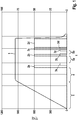
- Fig. 1 shows a graph for schematically illustrating an embodiment of the method according to the invention.
- the method comprises a heating phase 1, a temperature equalization phase 4, four nitriding phases 2a, 2b, 2c, 2d, four carburizing phases 3a, 3b, 3c, 3d and two diffusion phases 5a, 5b.
- FIG. 1 shows that during the heating phase 1, the temperature is continuously increased at a constant heating rate up to a treatment temperature of about 950 ° C.
- the treatment temperature is kept constant at about 950 ° C.
- neither a nitrogen donor gas nor a carbon donor gas is supplied.
- a nitrogen donor gas for example ammonia
- a nitrogen donor gas partial pressure of about 50 mbar.
- the treatment temperature is kept constant at about 950 ° C, as in the following nitriding phases 2b, 2c, 2d, carburizing phases 3a, 3b, 3c, 3d and diffusion phases 5a, 5b.
- the first nitriding phase 2a is followed by a first carburizing phase 3a, in which the nitrogen donor gas partial pressure is reduced again to 0 mbar and the carbon donor gas partial pressure is increased to about 10 mbar.
- the first carburization phase 3a is followed by a first diffusion phase 5a, in which the carbon donor gas partial pressure is lowered again to 0 mbar. This can be done, for example, by evacuating the treatment chamber or filling the treatment chamber with an inert gas.
- the first diffusion phase 5a is followed by a second carburizing phase 3b having a carbon donor gas partial pressure of about 10 mbar and a second nitriding phase 2b having a nitrogen donor gas partial pressure of about 50 mbar.
- FIG. 1 shows that the second carburizing phase 3b and the second nitriding phase 2b start simultaneously.
- the second carburizing phase 3b is longer than the second nitriding phase 2b and thus ends only after the nitriding phase 2b.
- the nitrogen donor gas partial pressure is lowered to 0 mbar and the carbon donor gas partial pressure of about 10 mbar is maintained until the end of the second carburizing phase 3b.
- the second carburization phase 3b is followed by a second diffusion phase 5b in which the carburizing donor gas partial pressure is lowered again to 0 mbar.
- the second diffusion phase 5b in turn is followed by a third carburizing phase 3c with a carbon donor gas partial pressure of about 10 mbar.
- a third carburizing phase 3c with a carbon donor gas partial pressure of about 10 mbar.
- the carbon donor gas partial pressure is lowered to 0 mbar and a third nitridation phase 2c is run with a nitrogen donor gas partial pressure of about 50 mbar.
- a fourth carburizing phase 3d in which the nitrogen donor gas partial pressure is lowered to 0 mbar and the carbon donor gas partial pressure is increased to about 10 mbar.
- the carbon donor gas partial pressure is lowered back to 0 mbar and a fourth nitridation phase 2d is run with a nitrogen donor gas partial pressure of about 50 mbar, which is very long compared to the previous nitriding phases 2a-2c.
- the treatment temperature of 950 ° C is no longer maintained and quenched to room temperature to adjust the desired microstructural composition.
Landscapes
- Chemical & Material Sciences (AREA)
- Chemical Kinetics & Catalysis (AREA)
- Engineering & Computer Science (AREA)
- Materials Engineering (AREA)
- Mechanical Engineering (AREA)
- Metallurgy (AREA)
- Organic Chemistry (AREA)
- Solid-Phase Diffusion Into Metallic Material Surfaces (AREA)
Description
- Die vorliegende Erfindung betrifft ein Verfahren zur Carbonitrierung mindestens eines Metallteils.
- Verfahren zur Carbonitrierung von Metallteilen sind aus den Druckschriften
DE 199 09 694 A1 ,DE 101 18 494 A1 undDE 103 22 255 A1 bekannt. - Die Druckschrift
DE 199 09 694 A1 beschreibt ein Carbonitrierungsverfahren, in dem die Eindiffusion des Stickstoffs während des gesamten Prozesses oder bei Verwendung von Stickstoff als Spendergas vorzugsweise allein in der letzten Prozessphase erfolgt. - Die Druckschrift
DE 101 18 494 C2 beschreibt ein Niederdruck-Carbonitrierungsverfahren, in dem Stahlteile zunächst aufgekohlt und anschließend mit einem Stickstoffspendergas aufgestickt werden. - Die Druckschrift
DE 103 22 255 A1 beschreibt ein Verfahren zur Aufkohlung von Stahlteilen, in dem sowohl während der Aufheizphase als auch während der Diffusionsphase stickstoffabgebendes Gas zugegeben wird. - Die
EP 1752551 A1 offenbart ein Verfahren zur Carbonitrierung eines Metallteils mit einer Aufstickungsphase, die eine Mehrzahl von Begasungszyklen umfasst und von einer Aufkohlungsphase gefolgt wird. - Durch ein Aufsticken nach oder während der letzten Aufkohlungsphase wird jedoch nur in einem oberflächennahen Bereich, der eine geringere Tiefe aufweist als der aufgekohlte Bereich, Stickstoff angereichert. Dies führt dazu, dass die Anlassbeständigkeit, Härte, Festigkeit und Verschleißbeständigkeit im aufgekohlten Bereich nicht ausreichend erhöht werden kann.
- Eine Aufstickung während der Aufheizphase führt hingegen zu einer inhomogenen Anlassbeständigkeit, Härte, Festigkeit und/oder Verschleißbeständigkeit innerhalb des Metallteils oder innerhalb einer Charge von Metallteilen.
- Der Erfindung liegt damit die Aufgabe zu Grunde, ein Verfahren zur Carbonitrierung von Metallteilen zur Verfügung zu stellen, mit dem die Anlassbeständigkeit und/oder Härtbarkeit eines Metallteils verbessert und/oder eine mit der Aufkohlungstiefe vergleichbare Aufstickungstiefe erzielt werden kann.
- Diese Aufgabe wird durch das erfindungsgemäße Verfahren zur Carbonitrierung mindestens eines Metallteils gelöst, in dem das Metallteil in einer Aufheizphase auf eine Behandlungstemperatur aufgeheizt, in mindestens einer Aufstickungsphase mit einem Stickstoffspendergas aufgestickt und in mindestens einer Aufkohlungsphase mit einem Kohlenstoffspendergas aufgekohlt wird und das dadurch gekennzeichnet ist, dass die erste Aufstickungsphase nach dem Abschluss der Aufheizphase und vor dem Beginn der ersten Aufkohlungsphase beginnt und während, mit oder nach der ersten Aufkohlungsphase endet, wobei das Verfahren zwischen der Aufheizphase und der ersten Aufstickungsphase eine Temperaturvergleichmäßigungsphase aufweist, in welcher die Behandlungstemperatur zur Vergleichmäßigung der Temperatur innerhalb des Metallteils oder zwischen mehreren Metallteilen, insbesondere bei einer konstanten Atmosphäre, konstant gehalten wird, wobei das Verfahren ein Niederdruck-Carbonitrierungsverfahren ist, wobei die Behandlungstemperatur in einem Bereich von ≥ 780 °C bis ≤ 1050 °C liegt, und wobei während der Aufstickungsphase ein Stickstoffspendergas-Partialdruck von unter 500 mbar vorliegt.
- Dass die erste Aufstickungsphase erst nach dem Abschluss der Aufheizphase beginnt hat den Vorteil, dass Temperaturgradienten innerhalb des Metallteils oder innerhalb einer Charge von mehreren Metallteilen vermindert werden können und dadurch eine inhomogene Anlassbeständigkeit, Härte, Festigkeit und/oder Verschleißbeständigkeit innerhalb des Metallteils oder innerhalb einer Charge von Metallteilen vermieden werden kann.
- Dass mit der ersten Aufkohlungsphase erst nach dem Beginn der Aufstickungsphase begonnen wird, hat den Vorteil, dass der in die Oberfläche des Metallteils eingetragene Stickstoff über die ganze weitere Behandlungsdauer in das Metallteil diffundieren kann und zur Erhöhung der Anlassbeständigkeit, Härte, Festigkeit und Verschleißbeständigkeit in der Randzone beiträgt.
- Darüber hinaus wird dadurch, dass mit der ersten Aufkohlungsphase erst nach dem Beginn der Aufstickungsphase begonnen wird, die Stickstoffdiffusion beziehungsweise Kohlenstoffdiffusion beschleunigt. Dies liegt darin begründet, dass Stickstoffatome und Kohlenstoffatome die gleichen Zwischengitterplätze im Kristallgitter des Metalls belegen können. Mit der Durchführung einer Aufkohlungsphase im Anschluss an eine Aufstickungsphase können frei werdende oberflächennahe Zwischengitterplätze durch Kohlenstoffatome belegt werden und somit die Effusion von Stickstoffatomen und die damit verbundene Stickstoffdiffusion zur Oberfläche hin erschwert werden. Dadurch kann mit der vorgeschlagenen Prozessführung auch eine Reduzierung der im Niederdruckbereich vorkommenden und bekannten Stickstoffeffusion erreicht werden.
- Weiterhin kann der Stickstoff durch das frühzeitige Stickstoffangebot verhältnismäßig, beispielsweise bis zu 1,5 mm oder sogar bis zu 6 mm, tief in die Randschicht des Metallteils eingebracht werden. Dadurch kann bei Metallteilen, beispielsweise mit einer Betriebstemperatur von bis zu 300 °C oder sogar bis zu 350 °C, eine Erhöhung der Anlassbeständigkeit im Randbereich erzielt, eine ausreichende Härte, Festigkeit und/oder Verschleißbeständigkeit erreicht und/oder eine dauerhafte Funktion des Metallteils gewährleistet werden.
- Ferner kann mit dem erfindungsgemäßen Verfahren eine Randkohlenstoffkonzentration vorn ≥ 0,3 Massenprozent bis ≤ 0,7 Massenprozent oder sogar von bis zu 1 Massenprozent, und eine Randstickstoffkonzentration von ≥ 0,1 Massenprozent bis ≤ 0,35 Massenprozent oder sogar von bis zu 0,5 Massenprozent erzielt werden. Zur Erhöhung der Anlassbeständigkeit, Härte, Festigkeit und/oder Verschleißbeständigkeit kann im Bereich der Aufkohlungstiefe, beispielsweise bis zu 1,5 mm oder sogar bis zu 6 mm tief, vorteilhafterweise eine Stickstoffkonzentration von mindestens 0,05 Massenprozent, gegebenenfalls von mindestens 0,15 Massenprozent, erreicht werden sein.
- Insbesondere kann das erfindungsgemäße Verfahren zur Carbonitrierung der Randschicht eines Metallteils eingesetzt werden. Das erfindungsgemäße Verfahren kann auch zur Carbonitrierung von mehreren Metallteilen eingesetzt werden. Zum Beispiel kann das erfindungsgemäße Verfahren zur Carbonitrierung von einem oder mehreren metallischen Werkstücken eingesetzt werden.
- Bei dem Metall des Metallteils kann es sich sowohl um ein Metall als auch um eine Metalllegierung, beispielsweise Stahl, handeln.
- Im Rahmen des erfindungsgemäßen Verfahrens endet die erste Aufstickungsphase, insbesondere direkt vor der ersten Aufkohlungsphase oder während der ersten Aufkohlungsphase oder mit der ersten Aufkohlungsphase oder nach der ersten Aufkohlungsphase. Dadurch, dass die erste Aufkohlungsphase direkt an die erste Aufstickungsphase anschließt oder zumindest teilweise gleichzeitig mit der ersten Aufstickungsphase abläuft kann die Stickstoffeffusion während weiterer Aufkohlungsphasen, weiterer Aufstickungsphasen oder Diffusionsphasen reduziert oder verhindert werden.
- Weiterhin kann das erfindungsgemäße Verfahren mindestens eine zweite Aufstickungsphase aufweisen. Diese kann beispielsweise nach der ersten Aufkohlungsphase ablaufen. Insbesondere kann die zweite Aufstickungsphase im Anschluss an die erste Aufkohlungsphase beginnen.
- Im Rahmen des erfindungsgemäßen Verfahrens weist das Verfahren zwischen der Aufheizphase und der ersten Aufstickungs-phase eine Temperaturvergleichmäßigungsphase auf, in welcher die Behandlungstemperatur zur Vergleichmäßigung der Temperatur in dem Metallteil oder zwischen mehreren Metallteilen, insbesondere bei einer konstanten Atmosphäre, konstant gehalten wird. Dabei kann unter einer konstanten Atmosphäre sowohl Vakuum als auch eine, vorzugsweise inerte, Gasatmosphäre mit konstantem Druck und konstanter Zusammensetzung verstanden werden. Insbesondere kann die Temperaturvergleichmäßigungsphase anschließend an die Aufheizphase ablaufen. Die erste Aufstickungsphase kann wiederum anschließend an die Temperaturvergleichmäßigungsphase ablaufen. Die Temperaturvergleichmäßigungsphase kann zum Beispiel mindestens 5 min, insbesondere 30 min, dauern. Eine Temperaturvergleichmäßigungsphase hat den Vorteil, dass Temperaturgradienten innerhalb des Metallteils oder innerhalb einer Charge von mehreren Metallteilen weiter vermindert werden können und dadurch eine inhomogene Anlassbeständigkeit, Härte, Festigkeit und/oder Verschleißbeständigkeit innerhalb des Metallteils oder innerhalb einer Charge von Metallteilen weiter vermieden werden kann.
- In den auf die Temperaturvergleichmäßigungsphase folgenden Phasen, beispielsweise Aufstickungsphasen, Aufkohlungsphasen und/oder Diffusionspha sen, kann die Behandlungstemperatur weiterhin konstant, insbesondere auf der gleichen Behandlungstemperatur wie in der Temperaturvergleichmäßigungsphase, gehalten werden. Eine Erhöhung oder Absenkung der Temperatur bei einer anschließenden Behandlungsphase ist jedoch denkbar.
- Im Rahmen einer weiteren Ausführungsform des erfindungsgemäßen Verfahrens wird das Verfahren in einer, insbesondere evakuierbaren, Behandlungskammer durchgeführt.
- Im Rahmen einer weiteren Ausführungsform des erfindungsgemäßen Verfahrens weist das Verfahren mindestens eine Diffusionsphase auf, in welcher die Behandlungskammer evakuiert und/oder mit einem Inertgas, beispielsweise Argon, gefüllt wird. Die erste Diffusionsphase kann beispielsweise zwischen der ersten Aufstickungsphase und der ersten Aufkohlungsphase oder zwischen der ersten Aufkohlungsphase und der zweiten Aufstickungsphase ablaufen.
- Im Rahmen einer weiteren Ausführungsform des erfindungsgemäßen Verfahrens weist das Verfahren neben der ersten Aufstickungsphase mindestens eine weitere Aufstickungsphase und/oder neben der ersten Aufkohlungsphase mindestens eine weitere Aufkohlungsphase und/oder neben der ersten Diffusionsphase mindestens eine weitere Diffusionsphase auf. Die weiteren Aufstickungsphasen und/oder weiteren Aufkohlungsphasen können sowohl, insbesondere direkt, hintereinander, beispielsweise alternierend, als auch teilweise oder vollständig gleichzeitig ablaufen. Durch gleichzeitige oder hintereinander ablaufende Aufstickungsphasen und Aufkohlungsphasen kann die Kohlenstoff- und Stickstoffdiffusion im Gefüge des Metallteils vorteilhafterweise erhöht werden. Zwischen den weiteren Aufstickungsphasen und/oder weiteren Aufkohlungsphasen können darüber hinaus weitere Diffusionsphasen ablaufen. Beispielsweise kann eine weitere Aufkohlungsphase während oder im Anschluss an eine weitere Aufstickungsphase beginnen oder eine weitere Aufstickungsphase während oder im Anschluss an eine Aufkohlungsphase beginnen. Nach dem Abschluss dieser beiden Phasen kann dann zum Beispiel eine weitere Diffusionsphase beginnen.
- Im Rahmen einer weiteren Ausführungsform des erfindungsgemäßen Verfahrens umfasst das Stickstoffspendergas eine Verbindung, ausgewählt aus der Gruppe bestehend aus Ammoniak, Stickstoff und Mischungen davon, insbesondere Am moniak. Insbesondere kann das Stickstoffspendergas aus einer Verbindung, ausgewählt aus der Gruppe bestehend aus Ammoniak, Stickstoff und Mischungen davon, insbesondere Ammoniak, bestehen.
- Im Rahmen einer weiteren Ausführungsform des erfindungsgemäßen Verfahrens umfasst das Kohlenstoffspendergas eine Verbindung, ausgewählt aus der Gruppe bestehend aus Acetylen, Ethylen, Propan, Propen, Methan und Mischungen davon. Insbesondere kann das Kohlenstoffspendergas aus einer Verbindung, ausgewählt aus der Gruppe bestehend aus Acetylen, Ethylen, Propan, Propen, Methan und Mischungen davon, bestehen.
- Im Rahmen des erfindungsgemäßen Verfahrens ist das Verfahren ein Niederdruck-Carbonitrierungsverfahren.
- Im Rahmen des erfindungsgemäßen Verfahrens liegt die Behandlungstemperatur in einem Bereich von ≥ 780 °C bis ≤ 1050 °C, insbesondere von ≥ 780 °C bis ≤ 950 °C.
- Im Rahmen des erfindungsgemäßen Verfahrens liegt während der Aufstickungsphasen ein Stickstoffspendergas-Partialdruck von unter 500 mbar, beispielsweise von unter 100 mbar, insbesondere von unter oder gleich 50 mbar, zum Beispiel von unter 20 mbar, vor. Während der Aufkohlungsphasen kann zum Beispiel ein Kohlenstoffspendergas-Partialdruck von unter 300 mbar, insbesondere von unter 20 mbar, beispielsweise von unter 10 mbar, vorliegen.
- Um Stickstoffverluste durch Stickstoffeffusion während einer Diffusionssequenz auszugleichen, kann während oder vor einer, insbesondere der Diffusionsphase vorgeschalteten, Aufstickungsphase die Temperatur, beispielsweise auf eine Temperatur, welche innerhalb eines Bereichs von 850 °C bis 950 °C liegt angepasst/erhöht; und/oder das Stickstoffangebot, beispielsweise durch eine Erhöhung des Stickstoffspendergas-Partialdrucks, beispielsweise auf 50 mbar oder 30 mbar, und/oder des Stickstoffspendergas-Volumendurchsatzes, beispielsweise auf 3000 l/h, erhöht werden. Auf diese Weise kann die Stickstoffkonzentration im oberflächennahen Bereich, beispielsweise von ≥ 0,1 mm bis ≤ 0,2 mm oder sogar von bis zu 0,3 mm, höher als im Endprodukt eingestellt und eine Stickstoffeffusion kompensiert werden. Wird die Stickstoffkonzentration in einer anschließenden Diffusionsphase nun aufgrund von Stickstoffeffusion verringert und nimmt beispielsweise auf eine Randstickstoffkonzentration von bis zu 0,5 Massenprozent oder beispielsweise auf ≥ 0,1 Massenprozent bis ≤ 0,35 Massenprozent ab, so kann eine Erhöhung der Anlassbeständigkeit und Härtbarkeit an der Oberfläche vorteilhafterweise trotzdem gewährleistet werden.
- Ein weiterer Gegenstand der vorliegenden Erfindung ist ein Metallteil, beispielsweise ein metallisches Werkstück, bei dem die Aufstickungstiefe größer als die Aufkohlungstiefe ist. Ein derartiges Metallteil kann durch ein erfindungsgemäßes Verfahren hergestellt werden. Vorteilhaft dabei ist, dass das Bauteil eine tiefreichende Stützwirkung unter mechanischer Belastung bei erhöhten Betriebstemperaturen aufweisen kann.
- Ein weiterer Gegenstand der vorliegenden Erfindung ist ein Metallteil, beispielsweise ein metallisches Werkstück, hergestellt durch ein erfindungsgemäßes Verfahren. Insbesondere kann bei einem derartigen Metallteil die Aufstickungstiefe größer als die Aufkohlungstiefe sein.
- Weitere Vorteile und vorteilhafte Ausgestaltungen der erfindungsgemäßen Gegenstände werden durch die Zeichnung veranschaulicht und in der nachfolgenden Beschreibung erläutert. Dabei ist zu beachten, dass die Zeichnung nur beschreibenden Charakter hat und nicht dazu gedacht ist, die Erfindung in irgendeiner Form einzuschränken.
-
Fig. 1 zeigt einen Graphen zur schematischen Veranschaulichung einer Ausführungsform des erfindungsgemäßen Verfahrens. - Im Rahmen der in
Figur 1 gezeigten Ausführungsform umfasst das Verfahren eine Aufheizphase 1, eine Temperaturvergleichmäßigungsphase 4, vier Aufstickungsphasen 2a, 2b, 2c, 2d, vier Aufkohlungsphasen 3a, 3b, 3c, 3d und zwei Diffusionsphasen 5a, 5b. -
Figur 1 zeigt, dass während der Aufheizphase 1 die Temperatur mit einer konstanten Aufheizrate kontinuierlich bis auf eine Behandlungstemperatur von etwa 950 °C erhöht wird. - In der an die Aufheizphase 1 anschließenden Temperaturvergleichmäßigungsphase 4 wird die Behandlungstemperatur konstant auf etwa 950 °C gehalten. Während der Aufheizphase 1 und der Temperaturvergleichmäßigungsphase 4 wird dabei weder ein Stickstoffspendergas noch ein Kohlenstoffspendergas zugeführt.
- In der an die Temperaturvergleichmäßigungsphase 4 anschließenden ersten Aufstickungsphase 2a wird ein Stickstoffspendergas, beispielsweise Ammoniak, mit einem Stickstoffspendergas-Partialdruck von etwa 50 mbar zugeführt. Die Behandlungstemperatur wird dabei ebenso wie in den folgenden Aufstickungsphasen 2b, 2c, 2d, Aufkohlungsphasen 3a, 3b, 3c, 3d und Diffusionsphasen 5a, 5b konstant auf etwa 950 °C gehalten. An die erste Aufstickungsphase 2a schließt sich eine erste Aufkohlungsphase 3a an, in welcher der Stickstoffspendergas-Partialdruck wieder auf 0 mbar gesenkt und der Kohlenstoffspendergas-Partialdruck auf etwa 10 mbar erhöht wird. An die erste Aufkohlungsphase 3a schließt sich eine erste Diffusionsphase 5a an, in welcher der Kohlenstoffspendergas-Partialdruck wieder auf 0 mbar gesenkt wird. Dies kann beispielsweise durch Evakuieren der Behandlungskammer oder Füllen der Behandlungskammer mit einem Inertgas erfolgen.
- An die erste Diffusionsphase 5a schließt sich eine zweite Aufkohlungsphase 3b mit einem Kohlenstoffspendergas-Partialdruck von etwa 10 mbar und eine zweite Aufstickungsphase 2b mit einem Stickstoffspendergas-Partialdruck von etwa 50 mbar an.
Figur 1 zeigt, dass die zweite Aufkohlungsphase 3b und die zweite Aufstickungsphase 2b gleichzeitig beginnen. Die zweite Aufkohlungsphase 3b ist jedoch länger als die zweite Aufstickungsphase 2b und endet daher erst nach der Aufstickungsphase 2b. In dem Zeitraum, in dem beide Phasen 2b, 3b gleichzeitig ablaufen, liegt ein Kohlenstoffspendergas-Partialdruck von etwa 10 mbar und ein Stickstoffspendergas-Partialdruck von etwa 50 mbar vor. Nach Abschluss der zweiten Aufstickungsphase 2b wird der Stickstoffspendergas-Partialdruck jedoch auf 0 mbar gesenkt und der Kohlenstoffspendergas-Partialdruck von etwa 10 mbar bis zum Ende der zweiten Aufkohlungsphase 3b aufrechterhalten. An die zweite Aufkohlungsphase 3b schließt eine zweite Diffusionsphase 5b an, in welcher der Aufkohlungsspendergas-Partialdruck erneut auf 0 mbar gesenkt wird. - An die zweite Diffusionsphase 5b schließt wiederum eine dritte Aufkohlungsphase 3c mit einem Kohlenstoffspendergas-Partialdruck von etwa 10 mbar an. Nach Abschluss der dritten Aufkohlungsphase 3c wird der Kohlenstoffspendergas-Partialdruck auf 0 mbar gesenkt und es läuft eine dritte Aufstickungsphase 2c mit einem Stickstoffspendergas-Partialdruck von etwa 50 mbar ab. An diese schließt sich wiederum eine vierte Aufkohlungsphase 3d an, in welcher der Stickstoffspendergas-Partialdruck auf 0 mbar gesenkt und der Kohlenstoffspendergas-Partialdruck auf etwa 10 mbar erhöht wird. Nach Abschluss der vierten Aufkohlungsphase 3d wird der Kohlenstoffspendergas-Partialdruck wieder auf 0 mbar gesenkt und es läuft eine vierte Aufstickungsphase 2d mit einem Stickstoffspendergas-Partialdruck von etwa 50 mbar ab, welche - verglichen mit den vorherigen Aufstickungsphasen 2a-2c - sehr lang ist. Nach dieser letzten Aufstickungsphase 2d wird die Behandlungstemperatur von 950 °C nicht weiter aufrecht gehalten und eine Abschreckung auf Raumtemperatur durchgeführt, um die gewünschte Gefügezusammensetzung einzustellen.
- Es versteht sich von selbst, dass auf diese Weise zahlreiche Verfahren zur Carbonitrierung möglich sind und die Erfindung nicht auf die erläuterte Abfolge und Anzahl von vier Aufstickungsphasen 2a, 2b, 2c, 2d, vier Aufkohlungsphasen 3a, 3b, 3c, 3d und zwei Diffusionsphasen 5a, 5b beschränkt ist.
Claims (6)
- Verfahren zur Carbonitrierung mindestens eines metallischen Metallteils, in dem das Metallteil- in einer Aufheizphase (1) auf eine Behandlungstemperatur aufgeheizt wird,- in mindestens einer Aufstickungsphase (2a-2d) mit einem Stickstoffspendergas aufgestickt wird, und- in mindestens einer Aufkohlungsphase (3a-3d) mit einem Kohlenstoffspendergas aufgekohlt wird,dadurch gekennzeichnet, dass
die erste Aufstickungsphase (2a) nach dem Abschluss der Aufheizphase (1) und vor dem Beginn der ersten Aufkohlungsphase (3a) beginnt und während, mit oder nach der ersten Aufkohlungsphase (3a) endet, wobeidas Verfahren zwischen der Aufheizphase (1) und der ersten Aufstickungsphase (2a) eine Temperaturvergleichmäßigungsphase (4) aufweist, in welcher die Behandlungstemperatur zur Vergleichmäßigung der Temperatur innerhalb des Metallteils oder zwischen mehreren Metallteilen, insbesondere bei einer konstanten Atmosphäre, konstant gehalten wird,
wobei das Verfahren ein Niederdruck-Carbonitrierungsverfahren ist,
wobei die Behandlungstemperatur in einem Bereich von ≥ 780 °C bis ≤ 1050 °C liegt, und
wobei während der Aufstickungsphase (2a-2d) ein Stickstoffspendergas-Partialdruck von unter 500 mbar vorliegt. - Verfahren nach Anspruch 1, dadurch gekennzeichnet, dass das Verfahren in einer, insbesondere evakuierbaren, Behandlungskammer durchgeführt wird.
- Verfahren nach Anspruch 2, dadurch gekennzeichnet, dass das Verfahren mindestens eine Diffusionsphase (5a, 5b) aufweist, in welcher die Behandlungskammer evakuiert und/oder mit einem Inertgas gefüllt wird.
- Verfahren nach Anspruch 3, dadurch gekennzeichnet, dass das Verfahren neben der ersten Aufstickungsphase (2a) mindestens eine weitere Aufstickungsphase (2b-2d) und/oder neben der ersten Aufkohlungsphase (3a) mindestens eine weitere Aufkohlungsphase (3b-3d) und/oder neben der ersten Diffusionsphase (5a) mindestens eine weitere Diffusionsphase (5b) aufweist.
- Verfahren nach einem der Ansprüche 1 bis 4, dadurch gekennzeichnet, dass das Stickstoffspendergas eine Verbindung, ausgewählt aus der Gruppe bestehend aus Ammoniak, Stickstoff und Mischungen davon, umfasst.
- Verfahren nach einem der Ansprüche 1 bis 5, dadurch gekennzeichnet, dass das Kohlenstoffspendergas eine Verbindung, ausgewählt aus der Gruppe bestehend aus Acetylen, Ethylen, Propan, Propen, Methan und Mischungen davon, umfasst.
Applications Claiming Priority (2)
| Application Number | Priority Date | Filing Date | Title |
|---|---|---|---|
| DE102009002985A DE102009002985A1 (de) | 2009-05-11 | 2009-05-11 | Verfahren zur Carbonitrierung |
| PCT/EP2010/053559 WO2010130484A2 (de) | 2009-05-11 | 2010-03-18 | Verfahren zur carbonitrierung |
Publications (2)
| Publication Number | Publication Date |
|---|---|
| EP2430210A2 EP2430210A2 (de) | 2012-03-21 |
| EP2430210B1 true EP2430210B1 (de) | 2018-01-24 |
Family
ID=42321146
Family Applications (1)
| Application Number | Title | Priority Date | Filing Date |
|---|---|---|---|
| EP10709725.5A Active EP2430210B1 (de) | 2009-05-11 | 2010-03-18 | Verfahren zur carbonitrierung |
Country Status (7)
| Country | Link |
|---|---|
| US (1) | US20120103473A1 (de) |
| EP (1) | EP2430210B1 (de) |
| JP (1) | JP5930960B2 (de) |
| CN (1) | CN102439194B (de) |
| BR (1) | BRPI1014267A2 (de) |
| DE (1) | DE102009002985A1 (de) |
| WO (1) | WO2010130484A2 (de) |
Families Citing this family (14)
| Publication number | Priority date | Publication date | Assignee | Title |
|---|---|---|---|---|
| DE102010028165A1 (de) * | 2010-04-23 | 2011-10-27 | Robert Bosch Gmbh | Verfahren zur Carbonitrierung von metallischen Bauteilen |
| CN102230151B (zh) * | 2011-07-20 | 2015-10-21 | 新大洲本田摩托有限公司 | 一种金属工件热处理工艺 |
| FR2981947B1 (fr) * | 2011-10-31 | 2014-01-03 | Peugeot Citroen Automobiles Sa | Procede de carbonitruration basse pression, a plage de temperature etendue dans une phase de nitruration initiale |
| FR2981948B1 (fr) * | 2011-10-31 | 2014-01-03 | Peugeot Citroen Automobiles Sa | Procede de carbonitruration basse pression, a gradient reduit de temperature dans une phase de nitruration initiale |
| DE102013006589A1 (de) * | 2013-04-17 | 2014-10-23 | Ald Vacuum Technologies Gmbh | Verfahren und Vorrichtung für das thermochemische Härten von Werkstücken |
| FR3004731B1 (fr) * | 2013-04-18 | 2016-05-13 | Peugeot Citroen Automobiles Sa | Procede de traitement thermochimique comportant une unique phase de nitruration avant une cementation |
| CN103361594A (zh) * | 2013-08-07 | 2013-10-23 | 湖南特科能热处理有限公司 | 一种钢制加工件表面渗碳氮化处理方法 |
| FR3028530B1 (fr) * | 2014-11-14 | 2020-10-23 | Peugeot Citroen Automobiles Sa | Procede et installation de carbonitruration de piece(s) en acier sous basse pression et haute temperature |
| DE102015213068A1 (de) | 2015-07-13 | 2017-01-19 | Robert Bosch Gmbh | Verfahren zum Nitrieren eines Bauteils |
| CN105420663B (zh) * | 2015-11-20 | 2018-07-10 | 贵州师范大学 | 一种钛合金碳氮复合渗的表面处理方法 |
| WO2017150908A1 (ko) * | 2016-03-02 | 2017-09-08 | 부산대학교 산학협력단 | 고내열, 고경도 및 내마모성 코팅막의 형성 방법, 고내열, 고경도 및 내마모성 코팅막 및 이를 포함하는 절삭 공구 |
| JP6759842B2 (ja) * | 2016-08-15 | 2020-09-23 | トヨタ自動車株式会社 | 鋼材の製造方法 |
| DE102018222387A1 (de) | 2018-12-20 | 2020-06-25 | Robert Bosch Gmbh | Verfahren zum Carbonitrieren eines Metallteils und Metallteil |
| FR3132720B1 (fr) * | 2022-02-11 | 2024-08-23 | Skf Aerospace France | Procédé de renforcement d’une pièce en acier par carbonitruration |
Citations (4)
| Publication number | Priority date | Publication date | Assignee | Title |
|---|---|---|---|---|
| EP0545069A1 (de) * | 1991-12-04 | 1993-06-09 | Leybold Durferrit GmbH | Verfahren zur Behandlung von Stählen und Refraktärmetallen |
| EP0707661A1 (de) * | 1994-04-22 | 1996-04-24 | Innovatique S.A. | Verfahren und ofen zum nitrieren von metallischen formteilen bei niedrigen druck |
| EP1247875A2 (de) * | 2001-04-04 | 2002-10-09 | Aichelin Industrieofenbau Ges.m.b.H. | Verfahren und Vorrichtung zur Niederdruck-Carbonitrierung von Stahlteilen |
| DE10322255A1 (de) * | 2003-05-16 | 2004-12-02 | Ald Vacuum Technologies Ag | Verfahren zur Hochtemperaturaufkohlung von Stahlteilen |
Family Cites Families (10)
| Publication number | Priority date | Publication date | Assignee | Title |
|---|---|---|---|---|
| JPS60165370A (ja) * | 1984-02-07 | 1985-08-28 | Ishikawajima Harima Heavy Ind Co Ltd | ステンレス鋼の窒化処理方法 |
| JPH0324258A (ja) * | 1989-06-20 | 1991-02-01 | Koyo Seiko Co Ltd | 浸炭鋼部品の表面硬化処理方法 |
| JP3960697B2 (ja) * | 1998-12-10 | 2007-08-15 | 株式会社日本テクノ | 浸炭および浸炭窒化処理方法 |
| DE19909694A1 (de) | 1999-03-05 | 2000-09-14 | Stiftung Inst Fuer Werkstoffte | Verfahren zum Varbonitrieren bei Unterdruckverfahren ohne Plasmaunterstützung |
| JP2003050321A (ja) * | 2001-08-06 | 2003-02-21 | Mitsubishi Cable Ind Ltd | 光ファイバ及びその製造方法 |
| DE60141304D1 (de) * | 2001-12-13 | 2010-03-25 | Koyo Thermo Sys Co Ltd | Vakuum-carbonitrierverfahren |
| JP4255877B2 (ja) * | 2004-04-30 | 2009-04-15 | 株式会社アライドマテリアル | 高強度・高再結晶温度の高融点金属系合金材料とその製造方法 |
| JP2007046088A (ja) * | 2005-08-09 | 2007-02-22 | Yuki Koshuha:Kk | 浸窒焼入品及びその製造方法 |
| JP2008106875A (ja) * | 2006-10-26 | 2008-05-08 | Nsk Ltd | 大型転がり軸受 |
| CN101186992B (zh) * | 2006-11-16 | 2010-11-17 | 有限会社结城高周波 | 渗氮淬火制品及其制造方法 |
-
2009
- 2009-05-11 DE DE102009002985A patent/DE102009002985A1/de not_active Withdrawn
-
2010
- 2010-03-18 CN CN201080020682.2A patent/CN102439194B/zh active Active
- 2010-03-18 EP EP10709725.5A patent/EP2430210B1/de active Active
- 2010-03-18 US US13/319,314 patent/US20120103473A1/en not_active Abandoned
- 2010-03-18 JP JP2012510179A patent/JP5930960B2/ja not_active Expired - Fee Related
- 2010-03-18 WO PCT/EP2010/053559 patent/WO2010130484A2/de not_active Ceased
- 2010-03-18 BR BRPI1014267A patent/BRPI1014267A2/pt not_active IP Right Cessation
Patent Citations (4)
| Publication number | Priority date | Publication date | Assignee | Title |
|---|---|---|---|---|
| EP0545069A1 (de) * | 1991-12-04 | 1993-06-09 | Leybold Durferrit GmbH | Verfahren zur Behandlung von Stählen und Refraktärmetallen |
| EP0707661A1 (de) * | 1994-04-22 | 1996-04-24 | Innovatique S.A. | Verfahren und ofen zum nitrieren von metallischen formteilen bei niedrigen druck |
| EP1247875A2 (de) * | 2001-04-04 | 2002-10-09 | Aichelin Industrieofenbau Ges.m.b.H. | Verfahren und Vorrichtung zur Niederdruck-Carbonitrierung von Stahlteilen |
| DE10322255A1 (de) * | 2003-05-16 | 2004-12-02 | Ald Vacuum Technologies Ag | Verfahren zur Hochtemperaturaufkohlung von Stahlteilen |
Also Published As
| Publication number | Publication date |
|---|---|
| WO2010130484A2 (de) | 2010-11-18 |
| US20120103473A1 (en) | 2012-05-03 |
| DE102009002985A1 (de) | 2010-11-18 |
| EP2430210A2 (de) | 2012-03-21 |
| CN102439194B (zh) | 2014-07-23 |
| JP5930960B2 (ja) | 2016-06-08 |
| JP2012526203A (ja) | 2012-10-25 |
| WO2010130484A3 (de) | 2011-01-13 |
| BRPI1014267A2 (pt) | 2016-04-12 |
| CN102439194A (zh) | 2012-05-02 |
Similar Documents
| Publication | Publication Date | Title |
|---|---|---|
| WO2010130484A2 (de) | Verfahren zur carbonitrierung | |
| EP2561111B1 (de) | Verfahren zur carbonitrierung von metallischen bauteilen | |
| DE10197283T5 (de) | Verfahren und Vorrichtung zur Vakuumwärmebehandlung | |
| DE102007047074A1 (de) | Verfahren zur Aufkohlung von Werkstücken sowie Verwendung | |
| US20180363123A1 (en) | Method And Facility For Carbonitriding One or More Steel Parts Under Low Pressure And At A High Temperature | |
| DE112014004502T5 (de) | Nitrierungs-Verfahren für ein Stahl-Element | |
| DE60223202T2 (de) | Verfahren zur niederdruck-aufkohlung | |
| US10494708B2 (en) | Carburization of steel components | |
| DE10322255B4 (de) | Verfahren zur Hochtemperaturaufkohlung von Stahlteilen | |
| WO1993017146A1 (de) | Verfahren zur thermochemisch-thermischen behandlung von einsatzstählen | |
| EP1333105B1 (de) | Verfahren zur Wärmebehandlung metallischer Werkstücke sowie wärmebehandeltes Werkstück | |
| KR101945006B1 (ko) | 초기 질화 단계에서 확장된 온도 범위를 갖는 저압 침탄 질화 방법 | |
| EP2536864B1 (de) | Verfahren zur carbonitrierung mindestens eines bauteils in einer behandlungskammer | |
| DE10254846B4 (de) | Verfahren zum Einsatzhärten von Bauteilen aus Warmarbeitsstählen mittels Unterdruckaufkohlung | |
| KR101945005B1 (ko) | 온도 감소 도중 최종 질화 단계를 갖는 침탄 질화 방법 | |
| WO2017050464A1 (de) | Bainitisiertes stahlbauteil und verfahren zur herstellung | |
| AT524143B1 (de) | Verfahren zur Härtung eines Sinterbauteils | |
| EP1745158B1 (de) | Verfahren zur oberflächenbehandlung | |
| DE69802525T2 (de) | Verfahren zum kontinuierlichen herstellen von stahlband mit verbesserten oberflächeneigenschaften zum tiefziehen | |
| DE10209382B4 (de) | Verfahren zur Aufkohlung von Bauteilen | |
| DE19714306C2 (de) | Verfahren zum Einsatzhärten von Sinterteilen | |
| DE3029339A1 (de) | Verfahren und vorrichtung zur behandlung elektrisch leitenden materials durch glimmentladung | |
| JP2006206938A (ja) | 機械部品の製造方法 | |
| DE112017004574T5 (de) | Verfahren zur Herstellung eines ferritischen Edelstahlprodukts | |
| DE102012212918A1 (de) | Verfahren zur Herstellung mindestens eines Bauteils und Steuer- und/oder Regeleinrichtung |
Legal Events
| Date | Code | Title | Description |
|---|---|---|---|
| PUAI | Public reference made under article 153(3) epc to a published international application that has entered the european phase |
Free format text: ORIGINAL CODE: 0009012 |
|
| 17P | Request for examination filed |
Effective date: 20111212 |
|
| AK | Designated contracting states |
Kind code of ref document: A2 Designated state(s): AT BE BG CH CY CZ DE DK EE ES FI FR GB GR HR HU IE IS IT LI LT LU LV MC MK MT NL NO PL PT RO SE SI SK SM TR |
|
| DAX | Request for extension of the european patent (deleted) | ||
| 17Q | First examination report despatched |
Effective date: 20150316 |
|
| GRAP | Despatch of communication of intention to grant a patent |
Free format text: ORIGINAL CODE: EPIDOSNIGR1 |
|
| INTG | Intention to grant announced |
Effective date: 20170928 |
|
| GRAS | Grant fee paid |
Free format text: ORIGINAL CODE: EPIDOSNIGR3 |
|
| GRAA | (expected) grant |
Free format text: ORIGINAL CODE: 0009210 |
|
| AK | Designated contracting states |
Kind code of ref document: B1 Designated state(s): AT BE BG CH CY CZ DE DK EE ES FI FR GB GR HR HU IE IS IT LI LT LU LV MC MK MT NL NO PL PT RO SE SI SK SM TR |
|
| REG | Reference to a national code |
Ref country code: GB Ref legal event code: FG4D Free format text: NOT ENGLISH |
|
| REG | Reference to a national code |
Ref country code: CH Ref legal event code: EP |
|
| REG | Reference to a national code |
Ref country code: AT Ref legal event code: REF Ref document number: 965839 Country of ref document: AT Kind code of ref document: T Effective date: 20180215 |
|
| REG | Reference to a national code |
Ref country code: IE Ref legal event code: FG4D Free format text: LANGUAGE OF EP DOCUMENT: GERMAN |
|
| REG | Reference to a national code |
Ref country code: DE Ref legal event code: R096 Ref document number: 502010014597 Country of ref document: DE |
|
| REG | Reference to a national code |
Ref country code: FR Ref legal event code: PLFP Year of fee payment: 9 |
|
| REG | Reference to a national code |
Ref country code: NL Ref legal event code: MP Effective date: 20180124 |
|
| REG | Reference to a national code |
Ref country code: LT Ref legal event code: MG4D |
|
| PG25 | Lapsed in a contracting state [announced via postgrant information from national office to epo] |
Ref country code: NL Free format text: LAPSE BECAUSE OF FAILURE TO SUBMIT A TRANSLATION OF THE DESCRIPTION OR TO PAY THE FEE WITHIN THE PRESCRIBED TIME-LIMIT Effective date: 20180124 |
|
| PG25 | Lapsed in a contracting state [announced via postgrant information from national office to epo] |
Ref country code: ES Free format text: LAPSE BECAUSE OF FAILURE TO SUBMIT A TRANSLATION OF THE DESCRIPTION OR TO PAY THE FEE WITHIN THE PRESCRIBED TIME-LIMIT Effective date: 20180124 Ref country code: HR Free format text: LAPSE BECAUSE OF FAILURE TO SUBMIT A TRANSLATION OF THE DESCRIPTION OR TO PAY THE FEE WITHIN THE PRESCRIBED TIME-LIMIT Effective date: 20180124 Ref country code: NO Free format text: LAPSE BECAUSE OF FAILURE TO SUBMIT A TRANSLATION OF THE DESCRIPTION OR TO PAY THE FEE WITHIN THE PRESCRIBED TIME-LIMIT Effective date: 20180424 Ref country code: FI Free format text: LAPSE BECAUSE OF FAILURE TO SUBMIT A TRANSLATION OF THE DESCRIPTION OR TO PAY THE FEE WITHIN THE PRESCRIBED TIME-LIMIT Effective date: 20180124 Ref country code: LT Free format text: LAPSE BECAUSE OF FAILURE TO SUBMIT A TRANSLATION OF THE DESCRIPTION OR TO PAY THE FEE WITHIN THE PRESCRIBED TIME-LIMIT Effective date: 20180124 Ref country code: CY Free format text: LAPSE BECAUSE OF FAILURE TO SUBMIT A TRANSLATION OF THE DESCRIPTION OR TO PAY THE FEE WITHIN THE PRESCRIBED TIME-LIMIT Effective date: 20180124 |
|
| PG25 | Lapsed in a contracting state [announced via postgrant information from national office to epo] |
Ref country code: SE Free format text: LAPSE BECAUSE OF FAILURE TO SUBMIT A TRANSLATION OF THE DESCRIPTION OR TO PAY THE FEE WITHIN THE PRESCRIBED TIME-LIMIT Effective date: 20180124 Ref country code: IS Free format text: LAPSE BECAUSE OF FAILURE TO SUBMIT A TRANSLATION OF THE DESCRIPTION OR TO PAY THE FEE WITHIN THE PRESCRIBED TIME-LIMIT Effective date: 20180524 Ref country code: GR Free format text: LAPSE BECAUSE OF FAILURE TO SUBMIT A TRANSLATION OF THE DESCRIPTION OR TO PAY THE FEE WITHIN THE PRESCRIBED TIME-LIMIT Effective date: 20180425 Ref country code: LV Free format text: LAPSE BECAUSE OF FAILURE TO SUBMIT A TRANSLATION OF THE DESCRIPTION OR TO PAY THE FEE WITHIN THE PRESCRIBED TIME-LIMIT Effective date: 20180124 Ref country code: PL Free format text: LAPSE BECAUSE OF FAILURE TO SUBMIT A TRANSLATION OF THE DESCRIPTION OR TO PAY THE FEE WITHIN THE PRESCRIBED TIME-LIMIT Effective date: 20180124 Ref country code: BG Free format text: LAPSE BECAUSE OF FAILURE TO SUBMIT A TRANSLATION OF THE DESCRIPTION OR TO PAY THE FEE WITHIN THE PRESCRIBED TIME-LIMIT Effective date: 20180424 |
|
| PG25 | Lapsed in a contracting state [announced via postgrant information from national office to epo] |
Ref country code: MT Free format text: LAPSE BECAUSE OF FAILURE TO SUBMIT A TRANSLATION OF THE DESCRIPTION OR TO PAY THE FEE WITHIN THE PRESCRIBED TIME-LIMIT Effective date: 20180124 |
|
| REG | Reference to a national code |
Ref country code: DE Ref legal event code: R097 Ref document number: 502010014597 Country of ref document: DE |
|
| PG25 | Lapsed in a contracting state [announced via postgrant information from national office to epo] |
Ref country code: IT Free format text: LAPSE BECAUSE OF FAILURE TO SUBMIT A TRANSLATION OF THE DESCRIPTION OR TO PAY THE FEE WITHIN THE PRESCRIBED TIME-LIMIT Effective date: 20180124 Ref country code: RO Free format text: LAPSE BECAUSE OF FAILURE TO SUBMIT A TRANSLATION OF THE DESCRIPTION OR TO PAY THE FEE WITHIN THE PRESCRIBED TIME-LIMIT Effective date: 20180124 Ref country code: EE Free format text: LAPSE BECAUSE OF FAILURE TO SUBMIT A TRANSLATION OF THE DESCRIPTION OR TO PAY THE FEE WITHIN THE PRESCRIBED TIME-LIMIT Effective date: 20180124 |
|
| REG | Reference to a national code |
Ref country code: CH Ref legal event code: PL |
|
| PG25 | Lapsed in a contracting state [announced via postgrant information from national office to epo] |
Ref country code: MC Free format text: LAPSE BECAUSE OF FAILURE TO SUBMIT A TRANSLATION OF THE DESCRIPTION OR TO PAY THE FEE WITHIN THE PRESCRIBED TIME-LIMIT Effective date: 20180124 Ref country code: SK Free format text: LAPSE BECAUSE OF FAILURE TO SUBMIT A TRANSLATION OF THE DESCRIPTION OR TO PAY THE FEE WITHIN THE PRESCRIBED TIME-LIMIT Effective date: 20180124 Ref country code: SM Free format text: LAPSE BECAUSE OF FAILURE TO SUBMIT A TRANSLATION OF THE DESCRIPTION OR TO PAY THE FEE WITHIN THE PRESCRIBED TIME-LIMIT Effective date: 20180124 Ref country code: DK Free format text: LAPSE BECAUSE OF FAILURE TO SUBMIT A TRANSLATION OF THE DESCRIPTION OR TO PAY THE FEE WITHIN THE PRESCRIBED TIME-LIMIT Effective date: 20180124 |
|
| PLBE | No opposition filed within time limit |
Free format text: ORIGINAL CODE: 0009261 |
|
| STAA | Information on the status of an ep patent application or granted ep patent |
Free format text: STATUS: NO OPPOSITION FILED WITHIN TIME LIMIT |
|
| REG | Reference to a national code |
Ref country code: BE Ref legal event code: MM Effective date: 20180331 |
|
| GBPC | Gb: european patent ceased through non-payment of renewal fee |
Effective date: 20180424 |
|
| REG | Reference to a national code |
Ref country code: IE Ref legal event code: MM4A |
|
| PG25 | Lapsed in a contracting state [announced via postgrant information from national office to epo] |
Ref country code: LU Free format text: LAPSE BECAUSE OF NON-PAYMENT OF DUE FEES Effective date: 20180318 |
|
| 26N | No opposition filed |
Effective date: 20181025 |
|
| PG25 | Lapsed in a contracting state [announced via postgrant information from national office to epo] |
Ref country code: IE Free format text: LAPSE BECAUSE OF NON-PAYMENT OF DUE FEES Effective date: 20180318 |
|
| PG25 | Lapsed in a contracting state [announced via postgrant information from national office to epo] |
Ref country code: BE Free format text: LAPSE BECAUSE OF NON-PAYMENT OF DUE FEES Effective date: 20180331 Ref country code: CH Free format text: LAPSE BECAUSE OF NON-PAYMENT OF DUE FEES Effective date: 20180331 Ref country code: SI Free format text: LAPSE BECAUSE OF FAILURE TO SUBMIT A TRANSLATION OF THE DESCRIPTION OR TO PAY THE FEE WITHIN THE PRESCRIBED TIME-LIMIT Effective date: 20180124 Ref country code: LI Free format text: LAPSE BECAUSE OF NON-PAYMENT OF DUE FEES Effective date: 20180331 Ref country code: GB Free format text: LAPSE BECAUSE OF NON-PAYMENT OF DUE FEES Effective date: 20180424 |
|
| PGFP | Annual fee paid to national office [announced via postgrant information from national office to epo] |
Ref country code: AT Payment date: 20200319 Year of fee payment: 11 |
|
| PG25 | Lapsed in a contracting state [announced via postgrant information from national office to epo] |
Ref country code: PT Free format text: LAPSE BECAUSE OF FAILURE TO SUBMIT A TRANSLATION OF THE DESCRIPTION OR TO PAY THE FEE WITHIN THE PRESCRIBED TIME-LIMIT Effective date: 20180124 Ref country code: HU Free format text: LAPSE BECAUSE OF FAILURE TO SUBMIT A TRANSLATION OF THE DESCRIPTION OR TO PAY THE FEE WITHIN THE PRESCRIBED TIME-LIMIT; INVALID AB INITIO Effective date: 20100318 |
|
| PGFP | Annual fee paid to national office [announced via postgrant information from national office to epo] |
Ref country code: CZ Payment date: 20200309 Year of fee payment: 11 |
|
| PG25 | Lapsed in a contracting state [announced via postgrant information from national office to epo] |
Ref country code: MK Free format text: LAPSE BECAUSE OF NON-PAYMENT OF DUE FEES Effective date: 20180124 |
|
| PG25 | Lapsed in a contracting state [announced via postgrant information from national office to epo] |
Ref country code: CZ Free format text: LAPSE BECAUSE OF NON-PAYMENT OF DUE FEES Effective date: 20210318 |
|
| REG | Reference to a national code |
Ref country code: AT Ref legal event code: MM01 Ref document number: 965839 Country of ref document: AT Kind code of ref document: T Effective date: 20210318 |
|
| PG25 | Lapsed in a contracting state [announced via postgrant information from national office to epo] |
Ref country code: AT Free format text: LAPSE BECAUSE OF NON-PAYMENT OF DUE FEES Effective date: 20210318 |
|
| PGFP | Annual fee paid to national office [announced via postgrant information from national office to epo] |
Ref country code: DE Payment date: 20250522 Year of fee payment: 16 |
|
| PGFP | Annual fee paid to national office [announced via postgrant information from national office to epo] |
Ref country code: FR Payment date: 20260324 Year of fee payment: 17 |
|
| PGFP | Annual fee paid to national office [announced via postgrant information from national office to epo] |
Ref country code: TR Payment date: 20260310 Year of fee payment: 17 |